JP4231514B2 - Image processing apparatus and image reading apparatus - Google Patents
Image processing apparatus and image reading apparatus Download PDFInfo
- Publication number
- JP4231514B2 JP4231514B2 JP2006160786A JP2006160786A JP4231514B2 JP 4231514 B2 JP4231514 B2 JP 4231514B2 JP 2006160786 A JP2006160786 A JP 2006160786A JP 2006160786 A JP2006160786 A JP 2006160786A JP 4231514 B2 JP4231514 B2 JP 4231514B2
- Authority
- JP
- Japan
- Prior art keywords
- unit
- image
- storage device
- data
- external storage
- Prior art date
- Legal status (The legal status is an assumption and is not a legal conclusion. Google has not performed a legal analysis and makes no representation as to the accuracy of the status listed.)
- Active
Links
Images


Classifications
-
- H—ELECTRICITY
- H04—ELECTRIC COMMUNICATION TECHNIQUE
- H04N—PICTORIAL COMMUNICATION, e.g. TELEVISION
- H04N1/00—Scanning, transmission or reproduction of documents or the like, e.g. facsimile transmission; Details thereof
- H04N1/00127—Connection or combination of a still picture apparatus with another apparatus, e.g. for storage, processing or transmission of still picture signals or of information associated with a still picture
- H04N1/00347—Connection or combination of a still picture apparatus with another apparatus, e.g. for storage, processing or transmission of still picture signals or of information associated with a still picture with another still picture apparatus, e.g. hybrid still picture apparatus
-
- G—PHYSICS
- G03—PHOTOGRAPHY; CINEMATOGRAPHY; ANALOGOUS TECHNIQUES USING WAVES OTHER THAN OPTICAL WAVES; ELECTROGRAPHY; HOLOGRAPHY
- G03G—ELECTROGRAPHY; ELECTROPHOTOGRAPHY; MAGNETOGRAPHY
- G03G15/00—Apparatus for electrographic processes using a charge pattern
- G03G15/50—Machine control of apparatus for electrographic processes using a charge pattern, e.g. regulating differents parts of the machine, multimode copiers, microprocessor control
- G03G15/5004—Power supply control, e.g. power-saving mode, automatic power turn-off
-
- G—PHYSICS
- G03—PHOTOGRAPHY; CINEMATOGRAPHY; ANALOGOUS TECHNIQUES USING WAVES OTHER THAN OPTICAL WAVES; ELECTROGRAPHY; HOLOGRAPHY
- G03G—ELECTROGRAPHY; ELECTROPHOTOGRAPHY; MAGNETOGRAPHY
- G03G15/00—Apparatus for electrographic processes using a charge pattern
- G03G15/50—Machine control of apparatus for electrographic processes using a charge pattern, e.g. regulating differents parts of the machine, multimode copiers, microprocessor control
- G03G15/5066—Machine control of apparatus for electrographic processes using a charge pattern, e.g. regulating differents parts of the machine, multimode copiers, microprocessor control by using information from an external support, e.g. magnetic card
-
- H—ELECTRICITY
- H04—ELECTRIC COMMUNICATION TECHNIQUE
- H04N—PICTORIAL COMMUNICATION, e.g. TELEVISION
- H04N1/00—Scanning, transmission or reproduction of documents or the like, e.g. facsimile transmission; Details thereof
- H04N1/21—Intermediate information storage
- H04N1/2104—Intermediate information storage for one or a few pictures
- H04N1/2158—Intermediate information storage for one or a few pictures using a detachable storage unit
-
- G—PHYSICS
- G03—PHOTOGRAPHY; CINEMATOGRAPHY; ANALOGOUS TECHNIQUES USING WAVES OTHER THAN OPTICAL WAVES; ELECTROGRAPHY; HOLOGRAPHY
- G03G—ELECTROGRAPHY; ELECTROPHOTOGRAPHY; MAGNETOGRAPHY
- G03G2215/00—Apparatus for electrophotographic processes
- G03G2215/00025—Machine control, e.g. regulating different parts of the machine
- G03G2215/00088—Machine control, e.g. regulating different parts of the machine by using information from an external support
- G03G2215/00092—Machine control, e.g. regulating different parts of the machine by using information from an external support the support being an IC card
-
- H—ELECTRICITY
- H04—ELECTRIC COMMUNICATION TECHNIQUE
- H04N—PICTORIAL COMMUNICATION, e.g. TELEVISION
- H04N1/00—Scanning, transmission or reproduction of documents or the like, e.g. facsimile transmission; Details thereof
- H04N1/00127—Connection or combination of a still picture apparatus with another apparatus, e.g. for storage, processing or transmission of still picture signals or of information associated with a still picture
- H04N1/00204—Connection or combination of a still picture apparatus with another apparatus, e.g. for storage, processing or transmission of still picture signals or of information associated with a still picture with a digital computer or a digital computer system, e.g. an internet server
-
- H—ELECTRICITY
- H04—ELECTRIC COMMUNICATION TECHNIQUE
- H04N—PICTORIAL COMMUNICATION, e.g. TELEVISION
- H04N1/00—Scanning, transmission or reproduction of documents or the like, e.g. facsimile transmission; Details thereof
- H04N1/00127—Connection or combination of a still picture apparatus with another apparatus, e.g. for storage, processing or transmission of still picture signals or of information associated with a still picture
- H04N1/00281—Connection or combination of a still picture apparatus with another apparatus, e.g. for storage, processing or transmission of still picture signals or of information associated with a still picture with a telecommunication apparatus, e.g. a switched network of teleprinters for the distribution of text-based information, a selective call terminal
- H04N1/00307—Connection or combination of a still picture apparatus with another apparatus, e.g. for storage, processing or transmission of still picture signals or of information associated with a still picture with a telecommunication apparatus, e.g. a switched network of teleprinters for the distribution of text-based information, a selective call terminal with a mobile telephone apparatus
-
- H—ELECTRICITY
- H04—ELECTRIC COMMUNICATION TECHNIQUE
- H04N—PICTORIAL COMMUNICATION, e.g. TELEVISION
- H04N2201/00—Indexing scheme relating to scanning, transmission or reproduction of documents or the like, and to details thereof
- H04N2201/0008—Connection or combination of a still picture apparatus with another apparatus
- H04N2201/001—Sharing resources, e.g. processing power or memory, with a connected apparatus or enhancing the capability of the still picture apparatus
-
- H—ELECTRICITY
- H04—ELECTRIC COMMUNICATION TECHNIQUE
- H04N—PICTORIAL COMMUNICATION, e.g. TELEVISION
- H04N2201/00—Indexing scheme relating to scanning, transmission or reproduction of documents or the like, and to details thereof
- H04N2201/0008—Connection or combination of a still picture apparatus with another apparatus
- H04N2201/0034—Details of the connection, e.g. connector, interface
- H04N2201/0037—Topological details of the connection
- H04N2201/0041—Point to point
-
- H—ELECTRICITY
- H04—ELECTRIC COMMUNICATION TECHNIQUE
- H04N—PICTORIAL COMMUNICATION, e.g. TELEVISION
- H04N2201/00—Indexing scheme relating to scanning, transmission or reproduction of documents or the like, and to details thereof
- H04N2201/0008—Connection or combination of a still picture apparatus with another apparatus
- H04N2201/0034—Details of the connection, e.g. connector, interface
- H04N2201/0048—Type of connection
- H04N2201/0049—By wire, cable or the like
-
- H—ELECTRICITY
- H04—ELECTRIC COMMUNICATION TECHNIQUE
- H04N—PICTORIAL COMMUNICATION, e.g. TELEVISION
- H04N2201/00—Indexing scheme relating to scanning, transmission or reproduction of documents or the like, and to details thereof
- H04N2201/0077—Types of the still picture apparatus
- H04N2201/0087—Image storage device
-
- H—ELECTRICITY
- H04—ELECTRIC COMMUNICATION TECHNIQUE
- H04N—PICTORIAL COMMUNICATION, e.g. TELEVISION
- H04N2201/00—Indexing scheme relating to scanning, transmission or reproduction of documents or the like, and to details thereof
- H04N2201/0077—Types of the still picture apparatus
- H04N2201/0094—Multifunctional device, i.e. a device capable of all of reading, reproducing, copying, facsimile transception, file transception
Landscapes
- Engineering & Computer Science (AREA)
- Multimedia (AREA)
- Signal Processing (AREA)
- Microelectronics & Electronic Packaging (AREA)
- Physics & Mathematics (AREA)
- General Physics & Mathematics (AREA)
- Facsimiles In General (AREA)
- Control Or Security For Electrophotography (AREA)
- Accessory Devices And Overall Control Thereof (AREA)
Description
本発明は、外部機器とデータ通信を行う通信部を有する画像処理装置に関する。 The present invention relates to an image processing apparatus having a communication unit that performs data communication with an external device .
従来、この種の画像処理装置として、特許文献1には、待機状態などの処理不能状態では、画像形成部や原稿読取部に通電されておらず、このような処理不能状態から処理可能なレディ状態に移行させるためには、所定の操作によりウオームアップなどの復帰処理を行なう必要があることが開示されている。 Conventionally, as an image processing apparatus of this type, Japanese Patent Application Laid-Open No. 2005-228561 discloses that in an unprocessable state such as a standby state, the image forming unit and the document reading unit are not energized, and ready for processing from such an unprocessable state. It is disclosed that in order to shift to a state, it is necessary to perform a return process such as warm-up by a predetermined operation.
また、近年、USBメモリなどの外部記憶機器を接続し、外部記憶機器との間で通信可能な画像処理装置が出現している。この画像処理装置では、USBメモリに記憶された画像を印刷出力する場合、画像処理装置にUSBメモリを接続し、USBメモリ内に記憶された画像の一覧リストを画像処理装置の操作画面上に表示し、印刷したい画像を選択すれば、指定された画像が印刷される。また、読み取った画像をUSBメモリなどの外部記憶機器に記憶させる場合、画像処理装置にUSBメモリを接続し、画像処理装置の操作パネルを操作して、記録先を指定して原稿読み取りを指示すると、原稿の読み取りと画像データのUSBメモリへの記憶が実行される。
ところで、外部記憶機器と通信可能な画像処理装置において、外部記憶機器に記憶された画像の印刷動作を行うには、まず画像処理装置の操作画面上に外部記憶機器に記憶された画像の一覧を表示し、印刷したい画像を選択する操作を受けて、画像処理装置の画像形成部のウオームアップを開始することになる。また、外部記憶機器への画像の記録動作を行うには、画像処理装置の操作画面上で原稿読取りと記録先の指定する操作を受けて、画像処理装置の原稿読取部のウオームアップを開始することになる。そのため、ウオームアップを開始するまでに所定の操作を必要とし、その分、復帰処理が遅れることになる。 By the way, in an image processing apparatus that can communicate with an external storage device, in order to perform a printing operation of an image stored in the external storage device, first, a list of images stored in the external storage device is displayed on the operation screen of the image processing device. In response to an operation of selecting an image to be displayed and printed, warm-up of the image forming unit of the image processing apparatus is started. In addition, in order to perform an image recording operation to the external storage device, a document reading operation on the operation screen of the image processing apparatus and an operation for specifying a recording destination are received, and a warm-up of the document reading unit of the image processing apparatus is started. It will be. Therefore, a predetermined operation is required before the warm-up is started, and the return process is delayed by that amount.
本発明は、上記に鑑み、復帰処理の開始を早期に行い、画像処理を実行する際の処理効率の向上を図り得る画像処理装置の提供を目的としている。 SUMMARY OF THE INVENTION In view of the above, an object of the present invention is to provide an image processing apparatus that can start restoration processing early and improve the processing efficiency when executing image processing.
上記目的を達成するため、本発明に係る画像処理装置は、入力された画像データに基づき画像形成を行う画像形成部と、原稿から読取り画像データを生成する原稿読取部と、前記画像形成部及び原稿読取部を画像処理不可能な処理不能状態から画像処理可能な処理可能状態へ復帰するための復帰処理を実行する制御部と、外部機器とのデータ通信が可能か否かを検出する検出部と、外部機器とデータ通信を行う通信部とを備え、前記復帰処理として、前記画像形成部の復帰処理である第1復帰処理と、前記原稿読取部の復帰処理である第2復帰処理とを含む複数種類の復帰処理とが準備されており、前記検出部が外部機器とのデータ通信が可能になったことを検出すると、前記制御部は、前記外部機器が外部記憶機器であるか否かを確認し、外部記憶機器であることを確認した場合に、前記複数の復帰処理の中から前記外部記憶機器に記憶されたデータ情報に基づいて操作者の利用する可能性の高い処理モードに対応する1つまたは複数の復帰処理を選択し実行することを特徴とする。 To achieve the above object, an image processing apparatus according to the present invention includes an image forming unit for forming an image based on inputted image data, and a document reading section for generating the read image data from a document, the image forming section and detection of detecting a control unit that executes a return process for returning the document reading section from the image processing impossible processing impossible state to the image processing can be ready for processing, whether it is possible to data communication with external equipment And a communication unit that performs data communication with an external device, and the return process includes a first return process that is a return process of the image forming unit and a second return process that is a return process of the document reading unit. When the detection unit detects that data communication with an external device is possible, the control unit determines whether the external device is an external storage device. Check If it is confirmed that a part storage devices, one corresponding to the high processing mode can be used around the operator based on the data information stored in said external memory device from a plurality of return processing or A plurality of return processes are selected and executed.
このことにより、操作者の利用傾向に応じて、画像形成部の復帰処理と原稿読取部の復帰処理を含む複数種類の復帰処理の中から、操作者の利用する可能性の高い処理モードに対応する復帰処理を選択し開始することができる。 As a result, depending on the usage trend of the operator, the processing mode most likely to be used by the operator can be selected from a plurality of types of restoration processing including restoration processing of the image forming unit and restoration processing of the document reading unit. The return process to be selected can be selected and started.
本発明の画像処理装置は、更に前記外部記憶機器に記憶されたデータの有無を識別する識別手段を含み、前記識別手段の識別結果に基づき、データが前記外部記憶機器に記憶されている場合、前記制御手段は前記画像形成部の復帰処理である第1復帰処理を実行し、記憶されていない場合、前記制御手段は前記原稿読取部の復帰処理である第2復帰処理を実行することを特徴とする。 The image processing apparatus of the present invention further includes identification means for identifying the presence or absence of data stored in the external storage device, and when data is stored in the external storage device based on the identification result of the identification means, The control unit executes a first return process that is a return process of the image forming unit, and if not stored, the control unit executes a second return process that is a return process of the document reading unit. And
このことにより、複数の復帰処理の中から、操作者が利用する可能性の高い処理モードに対応する復帰処理を選択し開始することができる。 This makes it possible to select and start a return process corresponding to a process mode that is likely to be used by the operator from among a plurality of return processes.
本発明の画像処理装置は、更に前記外部記憶機器に記憶された画像データのデータ形式を判定する判定手段を含み、前記判定手段の判定結果に基づき、予め定められた特定のデータ形式の画像データが記憶されている場合、前記制御手段は前記画像形成部の復帰処理である第1復帰処理を実行し、前記特定のデータ形式の画像データが記憶されていない場合、前記制御手段は前記原稿読取部の復帰処理である第2復帰処理を実行することを特徴とする。 The image processing apparatus of the present invention further includes a determination unit that determines a data format of the image data stored in the external storage device, and image data having a predetermined specific data format based on a determination result of the determination unit. Is stored, the control unit executes a first return process that is a return process of the image forming unit, and when the image data of the specific data format is not stored, the control unit A second return process, which is a part return process, is executed.
このことにより、複数の復帰処理の中から更に正確に適切な復帰処理を選択し開始することができる。 This makes it possible to select and start an appropriate return process more accurately from a plurality of return processes.
以上のとおり、検出部が外部機器とのデータ通信が可能になったことを検出すると、制御部は、外部機器が外部記憶機器であるか否かを確認し、外部記憶機器であることを確認した場合に、画像形成部の復帰処理と、原稿読取部の復帰処理とを含む複数種類の復帰処理の中から操作者の利用する可能性の高い処理モードに対応する復帰処理を選択し開始することができ、復帰までの待ち時間が短縮でき、処理効率を向上させることができる。
As described above, when the detection unit detects that data communication with the external device is possible, the control unit checks whether the external device is an external storage device and confirms that it is an external storage device. In this case, the restoration process corresponding to the processing mode most likely to be used by the operator is selected and started from a plurality of types of restoration processes including the restoration process of the image forming unit and the restoration process of the document reading unit. The waiting time until the return can be shortened, and the processing efficiency can be improved.
<第1の実施形態>
図1は、この発明の第1の実施形態に係る画像形成装置の概略の構成を示す図である。画像処理装置100は、上部に画像読取部110、中央部に画像形成部210、下部に用紙給紙部250を配置して構成されている。この画像処理装置100の上面に配置された透明ガラス体の原稿台111上には、原稿セットトレイ上にセットされた複数枚の原稿を1枚ずつ自動的に原稿台111上へ給送する自動原稿搬送装置112が備えられている。また、画像形成部210の一方の側面に後処理ユニット260が装着されているとともに、用紙給紙部250の下方に載置台を兼ねた多段給紙ユニット270が配置されている。
<First Embodiment>
FIG. 1 is a diagram showing a schematic configuration of an image forming apparatus according to a first embodiment of the present invention. The
原稿台111の下方に位置する画像読取部110は、第1の走査ユニット113、第2の走査ユニット114、光学レンズ115、光電変換素子であるCCDラインセンサ116を有し、自動原稿搬送装置112との関連した動作により、原稿台111上に載置された原稿の画像を所定の露光位置において相対的に走査して読み取る。第1の走査ユニット113は、原稿面上を露光する光源ランプユニット1、及び、原稿からの反射光像を所定の方向に反射させる第1ミラー2aを搭載している。光源ランプユニット1の照射光量は、光量センサ3によって検出される。第2の走査ユニット114は、第1ミラー2aで反射された原稿からの反射光を光電変換素子であるCCDラインセンサ116に導く第2ミラー2b及び第3ミラー2cを搭載している。光学レンズ115は、原稿からの反射光をCCDラインセンサ116の受光面に結像させる。
The
画像形成部210には、感光体ドラム222を所定の電位に帯電させる帯電器223、原稿読取部110又は外部装置から転送された画像データに応じてレーザ光を出射して感光体ドラム222上に静電潜像を形成するレーザスキャンユニット(以下、LSUという。)227、感光体ドラム222上に形成された静電潜像に現像ローラ228を介してトナーを供給してトナー像に顕像化する現像器224、感光体ドラム222上に形成されたトナー像を用紙に転写する転写器225、転写工程後の感光体ドラム222上に残留したトナー等を回収するクリーニング器226、転写工程後の感光体ドラム222から用紙を剥離する剥離器229が設けられている。レーザスキャンユニット227は、内部に画像データによって変調されたレーザ光を照射する半導体レーザ11、及び、回転によってレーザ光を主走査方向に偏光するポリゴンミラー12を図示しないレンズ群等とともに備えている。ポリゴンミラー12は、モータ13によって駆動される。モータ13の回転速度は、速度センサ14によって検出される。
The
画像形成部210には、トナー像が転写された用紙を加熱及び加圧して用紙上にトナー像を定着させる定着ユニット217が設けられている。定着ユニット217は、上側の加熱ローラ21と下側の加圧ローラ22との一対のローラを備えている。加熱ローラ21はヒータを備え、加熱ローラ21の温度は、温度センサ23によって検出される。さらに、定着ユニット217の排出側には、用紙の両面に画像を形成する両面画像形成モード時に用紙の前後を反転させるスイッチバック路221が形成されている。
The
定着ユニット217においてトナー像が定着された用紙は、必要に応じてスイッチバック路221を経て排紙ローラ219にて後処理装置260へと導かれ、ここでステープル処理や穿孔処理等の後処理が施された後、トレイ261上に排出される。
The paper on which the toner image has been fixed in the
用紙給紙部250は、本体側面に装着された手差トレイ254、両面ユニット255、給紙トレイ251と多段給紙ユニット270に備えられた給紙トレイ252,253で構成されている。また、これらの給紙トレイ251〜254は、複数枚の用紙を積層して収納する。また、給紙トレイ251〜254から給紙した用紙を画像形成部210における感光体ドラム222と転写器225との間の転写位置へと搬送するローラ等の搬送手段を備えている。両面ユニット255は、用紙を反転させるスイッチバック路221に通じており、両面画像形成モード時に表裏面が反転された用紙を一時貯留する。なお、両面ユニット255は通常の給紙トレイと交換可能にされている。
The
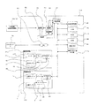
図2は、上記画像処理装置100の電気的構成を示すブロック図である。画像処理装置100は制御手段としてROM42及びRAM43を備えたメインCPU41を備える。そして、メインCPU41には画像メモリ44、画像処理回路48、HDD54、通信部50、検出部51、NIC53、操作手段(操作パネル)70、無線通信部54、サブCPU−A60、サブCPU−B61が接続されている。メインCPU41は、ROM42に予め書き込まれたプログラムにしたがって各入出機器を統括して制御し、この間に入出力されるデータをRAM43の所定のメモリエリアに一時記憶する。画像メモリ44は、画像処理回路48から出力された画像データを記憶する。
FIG. 2 is a block diagram showing an electrical configuration of the
操作手段(操作パネル)70は、入力キー及び液晶表示パネルを備え、装置の状態や利用可能な用紙サイズ、複写倍率等の表示を行うと共に、入力キーにより操作者の操作を受け付けることができる。液晶表示パネルは、液晶画面に触れることで入力が可能な液晶タッチパネルとしても良い。操作手段70は、操作者による外部記憶機器30の処理モードの入力を受け付ける受付手段でもある。
The operation means (operation panel) 70 includes an input key and a liquid crystal display panel. The operation means (operation panel) 70 displays the status of the apparatus, available paper size, copy magnification, and the like, and can accept an operator's operation with the input key. The liquid crystal display panel may be a liquid crystal touch panel that allows input by touching the liquid crystal screen. The
外部記憶機器30の処理モードとしては、原稿読取部110で読み取った画像データを外部記憶機器30に記憶する原稿読取モード(SCAN TO USB)、外部記憶機器30に記憶された画像データを画像形成部210により画像形成する画像形成モード(USB TO PRINT)、画像処理装置100内のHDD54に記憶されているデータを外部記憶機器30に記憶させるモード(FILE TO USB)、外部記憶機器30に記憶されているデータを画像処理装置内100のHDD54に記憶させるモード(USB TO FILE)が挙げられる。
The processing modes of the
通信部50は、外部機器(USB接続可能な機器)30aとメインCPU41とのデータ通信を行うインターフェイスである。接続部52は、外部機器30aとの接続がなされるUSB規格のコネクタである。検出部51は外部記憶機器30とのデータ通信の可否を検出する回路であり、詳細内容については後述する。
接続部52には、USB規格に準じた外部機器30aを接続することができる。外部機器30aには複数の種類があり、前述の外部記憶機器30であるUSBメモリの他に外付けキーボードや、装置の利用可能部門のみ与えられる部門カードを読み出し、装置利用を許可するためのカードリーダ等が含まれる。外部機器30aは、画像処理装置100に接続され画像処理装置100から電力が供給されると、機器の種類を示す機器識別データを接続先である画像処理装置100に送信する。機器識別データに基づいて画像処理装置100側で外部機器30aの種類に応じた制御を実施することができる。
The
An
NIC53はA Network Interface Cardの略称であり、クライアントPC55とネットワーク通信を行うための通信手段である。画像処理装置100はクライアントPC55から転送されるプリントデータに基づいて印刷を行う、もしくは原稿読取により得た画像データをNIC53を介してクライアントPC55に転送する。
The
無線通信部54は無線LAN、赤外線通信等の無線通信方法を用いて、後述する無線通信可能な外部機器30bとのデータ通信を行う。
The
画像形成部210は、サブCPU−A60により制御され、ヒータ21a、温度センサ23、ドライバ47、A/D変換器62を含む。温度センサ23は、定着ユニット217において加熱ローラ21の温度を検出して温度データをサブCPU−A60に出力する。メインCPU41は第1の復帰処理として、サブCPU−A60に所定のウオームアップコマンドを送信する。サブCPU−A60は、メインCPU41より所定のウオームアップコマンドを受けると、ヒータ21aに通電し、温度センサ23から得られる温度情報を基に、ヒータ21aにより加熱される加熱ローラ21の表面温度を所定の温度に一定化するようヒータ21aの通電を制御する。サブCPU−A60は加熱ローラ21の表面が所定温度に到達したならば、処理可能状態(レディ状態)に達したと判断して、メインCPU41に通知する。
The
原稿読取部110は、サブCPU−B61により制御され、光源ランプ1a、光量センサ3、ドライバ45、A/D変換器63を含む。光量センサ3は、光源ランプユニット1の光源ランプ1aが照射した光の光量を検出して光量データをサブCPU−B61に入力する。メインCPU41は第2の復帰処理として、サブCPU−B61に所定のウオームアップコマンドを送信する。サブCPU−B61は、メインCPU41より所定のウオームアップコマンドを受けると、光源ランプ1aに通電し、光量センサ3から得られる光量情報を基に、光源ランプ1aの光量が所定の光量に一定化するよう光源ランプ1aの通電を制御する。サブCPU−B61は光源ランプ1aの光量が所定の光量に到達したら、処理可能状態(レディ状態)に達したと判断して、メインCPU41に通知する。
The
ドライバ45は、サブCPU−B61から出力された制御データに基づいて光源ランプユニット1の光源ランプ1aを駆動する。ドライバ47は、サブCPU−A60から出力された制御データに基づいて定着ユニット217の加熱ローラ21に内蔵されたヒータ21aを駆動する。
The
サブCPU−A60,サブCPU−B61には、上記以外にも画像形成部及び原稿読取部内のモータ、クラッチ、ソレノイド及びセンサ等の原稿読取処理時及び画像形成処理時に動作する多数の入出力機器が接続されている。サブCPU−A60,サブCPU−B61には、原稿読取処理時及び画像形成処理時に所定のタイミングでセンサの検出データを読み取り、検出データに応じてモータ等を駆動する。
In addition to the above, the sub CPU-
外部機器30aとのデータ通信の可否を検出する検出部51について、図3に基づいて以下に説明する。
The
Vbusは、外部機器30aへ電力を供給するライン(+5V)であり、画像処理装置100の備える電源101はVbusを介して外部機器30aに電力を供給する。外部機器30a側には、データ入出力端子D+をVbusの電位へプルアップするプルアップ抵抗33が接続されている。プルアップ抵抗はデータ入出力端子D−に接続されていても良い。接続部52に外部機器30aが接続されると、データ入出力端子D+もしくはD−のいずれかがVbusとほぼ同電位となるので、検出部51はデータ入出力端子D+及びD−の電圧を検出して、Vbusとほぼ同電位となった場合、外部機器30aと画像処理装置100間のデータ通信が可能な状態となったことをメインCPU41に通知する。
Vbus is a line (+ 5V) that supplies power to the
(コピーモードの場合)
上記構成の画像処理装置100におけるコピーモードの処理について以下に示す。なお、コピーモードは、原稿の画像を読み取る画像読取処理、及び、読み取った画像を用紙上に複写する画像形成処理を含む。
(In copy mode)
Processing in the copy mode in the
コピーモード時には、原稿読取部110の原稿台111上に複写対象の原稿が載置された後、ユーザが操作パネル上の条件入力キー(複写枚数や複写倍率等)を入力した後に、スタートキーを押下すると画像読取処理及び画像形成処理を含むコピー動作が開始される。
In the copy mode, after the document to be copied is placed on the document table 111 of the
このようにして処理を開始する画像処理装置100は、まず、スタートキーが押されると、略同時に図示しないメイン駆動モータが始動し、各駆動ギヤが回転する。その後、給紙ローラ256が回転し用紙が給紙される、給紙された用紙は、搬送経路内をレジストローラ257まで搬送される。ここで、用紙は、感光体ドラム222上の画像先端部と同期をとるために一時停止し、用紙の先端部は均一にレジストローラ257に押しつけられて用紙の先端位置の補正が行なわれる。
In the
原稿読取部110において原稿読取中の画像情報は、光源ランプユニット1の光源ランプ1aが点灯し、走査ユニット113が矢印A方向へ移動することで露光走査が開始され、光源ランプユニット1から照射された光の原稿画像面における反射光は、ミラー2a〜2c及び光学レンズ115を経由してCCD116に受光され、画像情報として読み取られる。読み取られた画像情報は、画像処理回路48においてデジタルデータである画像データに変換される。画像データは、設定された条件で画像処理が施されて画像メモリ44に一旦記憶された後、LSU227に画像データとして供給される。
The image information during document reading in the
所定速度で回転する感光体ドラム222の表面は、帯電ユニット223からの電荷の付与を受け、所定の帯電電位に均一に帯電される。LSU227は、制御手段41から供給された画像データに基づいて半導体レーザ11を駆動し、画像データによって変調されたレーザ光を所定速度で回転するポリゴンミラー12を介して感光体ドラム222の表面に照射する。LSU227によるレーザ光の照射により、感光体ドラム222の表面には画像データに基づく静電潜像が形成される。静電潜像が形成された感光体ドラム222の表面には、現像ユニット224からトナーが供給され、静電潜像がトナー像に顕像化される。
The surface of the
用紙は、感光体ドラム222の回転に同期して回転を開始するレジストローラ256により、感光体ドラム222と転写器25との間に搬送され、転写器225によって感光体ドラム222の表面に担持されているトナー像の転写を受ける。感光体ドラム222の表面に残留したトナーは、紙粉等とともにクリーナ226によって除去及び回収される。
The sheet is conveyed between the
トナー像の転写を受けた用紙は、定着ユニット217に搬送され、加熱ローラ21と加圧ローラ22との間を通過する間に加熱及び加圧を受ける。用紙上に転写したトナー像は、一対のローラ21,22による加熱及び加圧によって溶融して用紙表面に堅牢に定着する。トナー像が定着した用紙は、排紙ローラ219を介して後処理装置260に排出される。
The sheet on which the toner image has been transferred is conveyed to the fixing
(プリントモードの場合)
画像処理装置100は、NIC53を介して入力されるクライアントPC55からの印刷データや、通信部50を介して接続される外部記憶機器30に記憶されている画像データを画像形成部210が備えるLSU227に転送し、印刷を実行する。
(In print mode)
The
(スキャンモードの場合)
画像処理装置100は、原稿読取部110で原稿の画像情報を読取り画像メモリ44に記憶した画像データをNIC53を介してクライアントPC55に転送したり、通信部50を介して接続される外部記憶機器30に転送する。
(In scan mode)
The
(ファイリングモードの場合)
画像処理装置100は、原稿読取部110で取得した画像データや通信部50を介して接続される外部記憶機器30から転送された画像データをHDD54に記憶する。記憶した画像データは、画像形成部210により印刷したり、NIC53を介してクライアントPC55に転送することができる。
(In filing mode)
The
以上のように、原稿読取部110と画像形成部210を備えた画像処理装置100の構成を示したが、本発明の実施においては原稿読取部を備え画像形成部を備えていない装置(原稿読取装置)であっても良いし、逆に画像形成部を備え原稿読取部を備えていない装置(画像形成装置)であっても良い。電気的構成としては、原稿読取装置は図2に示すブロック図から画像形成部210を除いた構成となり、画像形成装置は図2に示すブロック図から原稿読取部110を除いた構成である。
As described above, the configuration of the
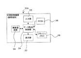
図4は外部記憶機器30の構成例を示すブロック図である。外部記憶機器の例として、USBメモリが挙げられる。
外部記憶機器30は、画像処理装置100の接続部52に接続されるコネクタ31と、画像処理装置100との通信制御を行うI/F部32と、画像データなどが記憶されるフラッシュメモリ38と、ROM36に記憶されている制御プログラムに基づいて、フラッシュメモリ38からI/F部32へのデータ読出及びI/F部32からフラッシュメモリ38へのデータ書込の制御を行うCPUなどのデータ転送制御部34とを備える。また、データ転送制御部34は、画像処理装置100の制御手段41との間で認証処理を行い、認証が成功した場合に通信部を介して画像処理装置100とのデータ転送を許可する。
FIG. 4 is a block diagram illustrating a configuration example of the
The
図5は、上記画像処理装置100の制御手段における第1の処理手順の要部を示すフローチャートである。フローチャートは、制御手段(メインCPU41)により、画像形成部210および/または原稿読取部110が画像処理不可能な処理不能状態で実行される。処理不能状態としては、節電のため画像形成部や原稿読取部に通電されていない状態(待機状態)、もしくは画像形成部や原稿読取部に通電はされているものの画像処理が可能な状態までに達していない状態(予熱状態)が相当する。待機状態も予熱状態も、画像形成部の定着ヒータ温度が所定温度に達していない状態、もしくは原稿読取部の光源ランプが所定光量に達していない状態となっている。
FIG. 5 is a flowchart showing the main part of the first processing procedure in the control means of the
画像処理装置100は、図示しない電源スイッチが投入されると、装置が停止した状態から処理可能状態(レディ状態)に移行するよう復帰処理(ウオームアップ)を実施する。処理可能状態に移行した後、所定の条件を満たすと、処理可能状態から処理不能状態(待機状態もしくは予熱状態)へ移行する。所定の条件としては、操作者による所定の操作、もしくは、最後の画像処理実行から所定時間(数分〜十数分。設定により変更可能)が経過したなどである。
When a power switch (not shown) is turned on, the
画像形成部210における処理可能状態とは、転写工程後に用紙を加熱及び加圧することによってトナー像を溶融して圧着させる定着ユニット227の加熱ローラ21が、画像形成処理可能なようにトナー像を溶融可能な所定温度まで上昇している状態を指す。復帰処理により、このように加熱ローラの温度を所定温度まで上昇させる。
The processable state in the
原稿読取部における処理可能状態とは、原稿台111に載置された原稿から画像情報を読み取るための光を照射する光源ランプユニット1の光源ランプ1aが、画像読取処理可能なように適正な濃度の画像データを得るための所定光量を照射している状態を指す。復帰処理により、このように光源ランプの光量を所定光量まで上昇させる。 The processable state in the document reading unit is an appropriate density so that the light source lamp 1a of the light source lamp unit 1 that emits light for reading image information from a document placed on the document table 111 can perform image reading processing. Indicates a state in which a predetermined amount of light for obtaining the image data is irradiated. The light amount of the light source lamp is thus increased to a predetermined light amount by the return process.
以下に、図5のフローチャートの詳細説明を行う。処理不能状態において、検出部51により、外部機器30aの接続を検出し、外部機器30aとの通信が可能な状態であることを検出する(S1010)と、外部機器30aと通信を実行し、外部機器30aから送信されてくる機器識別データを受信して、機器識別データに基づき、接続されている外部機器がデータの記憶が可能な外部記憶機器30(USBメモリ)であることを判定する(S1020)。外部機器30aが外部記憶機器30であれば、外部記憶機器30に指定回数が記憶されているか指定回数データの有無を判定する(S1025)。
Hereinafter, a detailed description of the flowchart of FIG. 5 will be given. In the unprocessable state, the
指定回数とは、処理モードが操作者により指定された回数の累計である。指定回数は記憶媒体に記憶される。記憶媒体としては外部記憶機器30を利用することができる。そのほかに記憶媒体としては画像処理装置100内のHDD54を利用しても良い。
The designated number is the total number of times that the processing mode is designated by the operator. The specified number of times is stored in the storage medium. An
指定回数が記憶されていれば(S1025のY)、S1030により以下の処理を行う。まず外部記憶装置30に記憶されている指定回数を参照する。指定回数とは、具体的には過去に利用したUSB TO PRINTの指定回数であるC1及び、SCAN TO USBの指定回数であるC2である。C1,C2を読み出して、指定回数C1が所定の回数である「C1+C2の合計の60%」以上であった場合(C1/(C1+C2)>0.6)(S1030のY)、USB TO PRINTの利用頻度が大であるため、定着ユニット217をウオームアップするよう、サブCPU−A60に定着ユニット217をウオームアップするコマンドを送信する(第1の復帰処理の実行)(S1040)。
If the designated number is stored (Y in S1025), the following processing is performed in S1030. First, the designated number stored in the
サブCPU−A60は、コマンドを受信すると、ヒータ21aを点灯し、加熱ローラを所定温度まで上昇させる。そうでない場合(S1030のN)、S1170を実行する。ここで指定回数C2が所定の回数である「C1+C2の合計の60%」以上であった場合(C2/(C1+C2)>0.6)(S1170のY)、SCAN TO USBの利用頻度が大であるため、光源ランプユニット1をウオームアップするよう、サブCPU−B61に光源ランプユニット1をウオームアップするコマンドを送信する(第2の復帰処理の実行)(S1180)。サブCPU−B61は、コマンドを受信すると、光源ランプ1aを点灯し、光源ランプ1aの光量を所定光量まで上昇させる。
When receiving the command, the sub CPU-
C2/(C1+C2)>0.6でない場合(S1170のN)、もしくは指定回数が外部記憶機器に記憶されていなかった場合(S1025のN)は、定着ユニット217と光源ランプユニット1の両方をウオームアップするよう、サブCPU−B61に光源ランプユニット1をウオームアップするコマンドを送信し(S1190)、サブCPU−A60に定着ユニット217をウオームアップするコマンドを送信する(S1200)。
If C2 / (C1 + C2)> 0.6 is not satisfied (N in S1170), or if the designated number is not stored in the external storage device (N in S1025), both the fixing
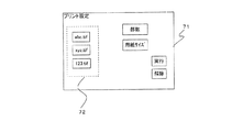
次に、操作パネル70に処理モードを選択するための選択画面の表示を行う(S1050)。このステップでは、外部記憶機器30を接続した時に利用する処理モードである、USB TO PRINT、SCAN TO USB、FILE TO USB(画像処理装置内のHDDに記憶されているデータを外部記憶機器30に記憶させる)、USB TO FILE(外部記憶機器30に記憶されているデータを画像処理装置内のHDDに記憶させる)の何れを使用するかをユーザが選択可能に表示される。操作パネル70上での画面表示の例を図6に示す。操作パネル70に備えた液晶タッチパネル71に選択可能な処理モードが表示され、操作者が所定の処理モードの表示部分に触れることで処理モードが指定できる。
Next, a selection screen for selecting a processing mode is displayed on the operation panel 70 (S1050). In this step, USB TO PRINT, SCAN TO USB, FILE TO USB (data stored in the HDD in the image processing apparatus is stored in the external storage device 30) which is a processing mode used when the
処理モードが入力される(S1060のY)と、既に外部記憶機器に指定回数が記憶されていた場合は、前述のC1、C2の数値を更新する。外部記憶機器に指定回数が記憶されていなかった場合、新たに指定回数としてC1、C2を外部記憶機器に新規記憶し、以降、指定回数として利用する(S1070)。 When the processing mode is input (Y in S1060), if the specified number of times has already been stored in the external storage device, the above-described numerical values of C1 and C2 are updated. If the specified number of times is not stored in the external storage device, C1 and C2 are newly stored in the external storage device as the specified number of times, and thereafter used as the specified number of times (S1070).
具体的には、C1、C2の更新の場合、USB TO PRINTが指定されると、USB TO PRINTの指定回数であるC1をインクリメント(+1)する。SCAN TO USBが指定されると、SCAN TO USBの指定回数であるC2をインクリメント(+1)する。新規記憶の場合、指定された処理モードに応じてC1=1、C2=0もしくはC1=0、C2=1として指定回数を記憶媒体に記憶する。 Specifically, in the case of updating C1 and C2, when USB TO PRINT is designated, C1 which is the designated number of USB TO PRINT is incremented (+1). When SCAN TO USB is designated, C2 which is the designated number of SCAN TO USB is incremented (+1). In the case of new storage, the specified number of times is stored in the storage medium as C1 = 1, C2 = 0 or C1 = 0, C2 = 1 according to the specified processing mode.
このように、指定回数を外部記憶機器30に記憶することで、各操作者がそれぞれ個人用として外部記憶機器30を所持していれば、各操作者の処理モードの利用頻度に応じて、複数の復帰処理の中から適切な復帰処理を選択実行することができる。
As described above, by storing the designated number of times in the
次に、操作者によって指定された処理モードを判定する(S1080)。USB TO PRINTの場合、図7に示すように外部記憶機器30内に記憶されているファイルのリスト72が表示される(1090)。操作者が印刷したいファイル、印刷部数、用紙サイズ等の印刷設定を指定し、印刷実行を指示する(S1100のY)と、定着ユニット217のウオームアップ完了を待って(S1110)、指定されたファイルの印刷を実行する(S1120)。
Next, the processing mode designated by the operator is determined (S1080). In the case of USB TO PRINT, a
SCAN TO USBの場合、光源ランプユニット1のウオームアップ完了を待って(S1130)、原稿読取を実行し、読み取った画像データを外部記憶機器30に記憶する(S1140)。 In the case of SCAN TO USB, after the warm-up of the light source lamp unit 1 is completed (S1130), the original is read and the read image data is stored in the external storage device 30 (S1140).
FILE TO USBもしくはUSB TO FILEの場合、操作者によるファイル指定を受け付け(S1150)、指定された外部記憶機器30内のファイルを画像処理装置内のHDDに記憶する。または指定された画像処理装置内のHDD内のファイルを外部記憶機器30に記憶する(S1160)。S1060で処理モードの指定入力を待機した状態(S1060のN)で、外部記憶機器30が本体から取り外されたことを検出したら(S1210)、定着ユニット217及び光源ランプユニット1のウオームアップを中断する(S1220)。
In the case of FILE TO USB or USB TO FILE, the file designation by the operator is accepted (S1150), and the designated file in the
具体的には、ヒータ21aと光源ランプ1aへの通電を切断するよう、もしくは予熱状態に移行するよう、サブCPU−A60およびサブCPU−B61にコマンドを転送する。そして外部機器30aの接続を待つ待機状態(S1010)に移行する。
Specifically, the command is transferred to the sub CPU-
<第2の実施形態>
図8は、上記画像処理装置100の制御手段における第2の処理手順の要部を示すフローチャートである。
<Second Embodiment>
FIG. 8 is a flowchart showing the main part of the second processing procedure in the control means of the
フローチャートは、制御手段(メインCPU41)により、画像形成部210および/または原稿読取部110が画像処理不可能な処理不能状態で実行される。
The flowchart is executed by the control means (main CPU 41) in an unprocessable state in which the
外部記憶機器内30の画像データの有無を識別する識別手段について以下に説明する。識別手段は、メインCPU41からなり、フラッシュメモリ38に記憶されるファイル管理テーブルの内容に基づき外部記憶機器内30のデータの有無を識別する。なお外部記憶機器内30が備えるデータ転送制御部34を識別手段として用い、データ転送制御部34がデータの有無を識別してメインCPU41に識別結果を送信する制御を実行するよう構成しても良い。
The identification means for identifying the presence / absence of image data in the
ファイル管理テーブルは、少なくともフラッシュメモリ38に記憶されている全データファイルの名称、データファイルのサイズ、データファイルの記憶開始アドレスを記録しており、データファイルの管理や、データファイルをアクセスするために用いられる。データファイルにアクセスする場合、メインCPU41は、ファイル管理テーブルの記録内容に基づき、所望のデータファイルを指定するコマンドをデータ転送制御部34に送信する。データ転送制御部34はコマンドを受信すると、当該データファイルを読み出して、メインCPU41に送信する。このような手順でデータファイルにアクセスすることができる。
The file management table records at least the names of all the data files stored in the
外部記憶機器内30の画像データのデータ形式を判定する判定手段について以下に説明する。判定手段は、メインCPU41からなり、ファイル管理テーブルの内容に基づき外部記憶機器内30の画像データのデータ形式を参照して、画像データが予め定められた特定のデータ形式か否かを判定する。なお外部記憶機器内30が備えるデータ転送制御部34を判定手段として用い、データ転送制御部34がデータ形式を判定してメインCPU41に判定結果を送信する制御を実行するよう構成しても良い。
The determination means for determining the data format of the image data in the
以下、図8に示すフローチャートの詳細説明を行う。S1010、S1020については第1実施例の説明と同様であり、説明を省略する。外部記憶機器のファイル管理テーブルを参照して、外部記憶機器に記憶されているデータファイルの有無を識別する(S2010)。具体的には、メインCPU41は、外部記憶機器30内のデータ転送制御部34に対し、フラッシュメモリ38に記憶されるファイル管理テーブルの内容を問い合わせるコマンドを送信する。データ転送制御部34はコマンドを受けると、ファイル管理テーブルの内容をメインCPU41に対して転送する。メインCPU41は、ファイル管理テーブルを参照して、データファイルの有無を識別する。
Hereinafter, detailed description of the flowchart shown in FIG. 8 will be given. S1010 and S1020 are the same as those described in the first embodiment, and a description thereof will be omitted. The presence or absence of a data file stored in the external storage device is identified with reference to the file management table of the external storage device (S2010). Specifically, the
データファイルが記憶されている場合(S2010のY)、ファイル管理テーブルを参照して、データファイルの拡張子に基づいて、データがUSB TO PRINTが可能な、特定のデータ形式の画像データか否かを判定する(S2020)。判定処理について詳説すると、ファイル管理テーブルに記録されたファイル名には、ファイル形式を判定するための形式データである拡張子が含まれている。拡張子が図9の判定テーブル記載のデータと合致したら、当該ファイルはビットマップ形式の画像データを含んでおり、USB TO PRINTが可能なファイル形式と判定する。例として拡張子がTIFF、JPEG、BMP、PDFを示していればビットマップの画像データを含んでおり、USB TO PRINTが可能である。いずれの画像形式がUSB TO PRINT可能かについては画像処理装置の仕様に応じて設定する必要がある。 When a data file is stored (Y in S2010), whether or not the data is image data of a specific data format capable of USB TO PRINT based on the extension of the data file with reference to the file management table Is determined (S2020). The determination process will be described in detail. The file name recorded in the file management table includes an extension that is format data for determining the file format. If the extension matches the data described in the determination table of FIG. 9, the file contains bitmap format image data, and is determined to be a file format capable of USB TO PRINT. For example, if the extension indicates TIFF, JPEG, BMP, or PDF, bitmap image data is included, and USB TO PRINT is possible. It is necessary to set which image format is USB TO PRINT according to the specifications of the image processing apparatus.
USB TO PRINTが可能な画像データがあると判定した場合(S2020のY)、定着ユニット217をウオームアップするよう、サブCPU−A60に定着ユニット217をウオームアップするコマンドを送信する(S2030)。データが外部記憶機器に記憶されていない、もしくはデータが記憶されていてもUSB TO PRINT可能な画像データでないと判定した場合(S2020のN)、光源ランプユニット1をウオームアップするよう、サブCPU−B61に光源ランプユニット1をウオームアップするコマンドを送信する(S2040)。S1050以降については第1の実施形態での説明と同様であり、その説明を省略する。
If it is determined that there is image data that can be USB TO PRINTed (Y in S2020), a command to warm up the fixing
以上、第2の実施形態について説明したが、他の実施形態として以下のような実施も可能である。すなわち、USB TO PRINTが可能な画像データが有ると判断した場合(S2020のY)、定着ユニット217のウオームアップと共に、光源ランプユニット1をウオームアップし、そうでない場合(S2010のNおよびS2020のN)、光源ランプユニット1のみウオームアップする。そのようにする理由は、外部記憶機器30にUSB TO PRINTが可能な画像データが有る場合でも、SCAN TO USBを利用する場合があるからである。他方、USB TO PRINTが可能な画像データが無い場合、USB TO PRINTを実施する可能性は無いので、定着ユニット217のウオームアップは不要である。
Although the second embodiment has been described above, the following embodiments are possible as other embodiments. That is, when it is determined that there is image data that can be USB TO PRINTed (Y in S2020), the light source lamp unit 1 is warmed up together with the warming up of the fixing
<第3の実施形態>
外部記憶機器30としてはUSBメモリ以外にも利用可能であり、以下に別の実施形態を述べる。以下は、外部記憶機器30として携帯電話、PDA等の携帯端末を無線通信可能な外部記憶機器30bとして利用する例を挙げる(図10参照)。
<Third Embodiment>
The
無線通信部39は、無線LAN、赤外線通信等の無線通信方法により画像処理装置100の備える無線通信部54やクライアントPCに接続された無線LAN等の無線通信装置との無線通信が可能に設けられている。入力部35はキースイッチ等により操作者の操作入力を受け付ける。表示部33は液晶パネル等により情報を表示する。その他の、図4と同一の符号の部材については説明を省略する。
The
上記の構成においては、無線通信を用いて画像処理装置100を利用してSCAN TO USBやUSB TO PRINTを実施する。画像処理装置100の無線通信部54内には、図示しない電磁波検出回路が設けられており、電磁波検出回路は無線通信可能な外部記憶機器30bの発する電磁波(無線通信部54に対するデータ送信電磁波)を検出して、外部記憶機器30bと画像処理装置100間のデータ通信の可否を検出する。無線通信の場合、電磁波検出回路が検出部に相当する。
In the above configuration, SCAN TO USB or USB TO PRINT is performed using the
更に、このように携帯端末30bを利用する場合、前記処理モードを入力する手段として入力部35を利用することができる。入力部35から入力された処理モードを無線通信により画像処理装置100へ向けて伝達する。この場合、無線通信部54が処理モードの入力を受け付ける受付手段に相当する。
Furthermore, when using the
<第4の実施形態>
図11は原稿読取装置での処理の例を示すフローチャートである。以下、このフローチャートに基づいて説明を行う。第1、第2の実施形態と共通の符号のステップについては同様であり、説明を省略する。
<Fourth Embodiment>
FIG. 11 is a flowchart illustrating an example of processing in the document reading apparatus. Hereinafter, description will be made based on this flowchart. The steps with the same reference numerals as those in the first and second embodiments are the same, and the description thereof is omitted.
外部機器30aの接続を検出し、外部記憶機器30であると判定すると(S1020のY)、光源ランプユニット1をウオームアップするよう、サブCPU−B61に光源ランプユニット1をウオームアップするコマンドを送信する(S2040)。そうでない場合(S1020のN)、ウオームアップは実施しない。SCAN TO USBの実施が操作者により指示されたら(S3010のY)ウオームアップ完了を待って、SCAN TO USBを実施する。外部記憶機器30が本体から取り外されたことを検出したら(S1210)、光源ランプユニット1のウオームアップを中断する(S3020)。具体的には、光源ランプ1aへの通電を切断するよう、もしくは予熱状態に移行するよう、サブCPU−B61にコマンドを転送する。そして外部機器30aの接続を待つ待機状態(S1010)に移行する。
If the connection of the
<第5の実施形態>
図12は画像形成装置での処理の例を示すフローチャートである。以下、このフローチャートに基づいて説明を行う。第1、第2の実施形態と共通の符号のステップについては同様であり、説明を省略する。
<Fifth Embodiment>
FIG. 12 is a flowchart illustrating an example of processing in the image forming apparatus. Hereinafter, description will be made based on this flowchart. The steps with the same reference numerals as those in the first and second embodiments are the same, and the description thereof is omitted.
USB TO PRINTが可能な画像データがあると判定した場合(S2020のY)、定着ユニット217をウオームアップするよう、サブCPU−A60に定着ユニット217をウオームアップするコマンドを送信する(S2030)。そうでない場合(S2020のN)、ウオームアップは実施せず、USB TO PRINTが不可の旨、表示手段70に表示する(S4030)。USB TO PRINTの実施が操作者により指示されたら(S4010のY)ウオームアップ完了を待って、USB TO PRINTを実施する。外部記憶機器30が本体から取り外されたことを検出したら(S1210)、定着ユニット217のウオームアップを中断する(S4020)。具体的には、ヒータ21aへの通電を切断するよう、もしくは予熱状態に移行するよう、サブCPU−A60にコマンドを転送する。そして外部機器30aの接続を待つ待機状態(S1010)に移行する。
If it is determined that there is image data that can be USB TO PRINTed (Y in S2020), a command to warm up the fixing
本発明の実施形態としては以上のとおりであるが、更に外部記憶機器として、USBメモリの他に、USB接続可能な記憶装置、例えばHDD、MOドライブであっても良い。更に接続の規格としてUSB以外の規格、例えば機器同士を繋ぐデジタルインターフェイスであるIEEE1394(Institute of Electrical and Electronic Engineers 1394) であっても良い。また、画像処理装置は、カラー複合機であっても良い。 Although the embodiment of the present invention is as described above, the external storage device may be a USB-connected storage device such as an HDD or an MO drive in addition to the USB memory. Further, a standard other than USB, for example, IEEE 1394 (Institute of Electrical and Electronic Engineers 1394) which is a digital interface for connecting devices may be used. The image processing apparatus may be a color complex machine.
また、本発明の復帰処理の例として定着ユニットと光源ランプユニットの復帰処理を示したが、これだけでなく以下の処理であっても良い。
1)ポリゴンミラー12を回転させるモータ13は、画像読取部が処理不能状態の期間中は停止している。復帰処理として、モータ13の回転を開始させ、読取処理が可能な所定の回転速度まで上昇させる処理。
2)現像器22が備える現像ローラ228を、画像形成部210が処理不能状態の期間中に停止している状態から、画像形成前に回転させる処理(予備回転)。
3)同様に、感光体ドラム222を、画像形成部210が処理不能状態の期間中に停止している状態から、画像形成前に回転させる処理。
In addition, although the restoration processing of the fixing unit and the light source lamp unit is shown as an example of the restoration processing of the present invention, the following processing is not limited thereto.
1) The
2) A process (preliminary rotation) in which the developing
3) Similarly, a process of rotating the
1 光源ランプユニット
1a 光源ランプ
3 光量センサ
12 ポリゴンミラー
13 モータ
14 速度センサ
21 加熱ローラ
21a ヒータ
23 温度センサ
100 画像処理装置
217 定着ユニット
210 画像形成部
222 感光体ドラム
227 LSU(レーザスキャンユニット)
DESCRIPTION OF SYMBOLS 1 Light source lamp unit 1a
Claims (11)
前記復帰処理として、前記画像形成部の復帰処理である第1復帰処理と、前記原稿読取部の復帰処理である第2復帰処理とを含む複数種類の復帰処理とが準備されており、
前記検出部が外部機器とのデータ通信が可能になったことを検出すると、前記制御部は、前記外部機器が外部記憶機器であるか否かを確認し、外部記憶機器であることを確認した場合に、前記複数の復帰処理の中から前記外部記憶機器に記憶されたデータ情報に基づいて操作者の利用する可能性の高い処理モードに対応する1つまたは複数の復帰処理を選択し実行することを特徴とする画像処理装置。 An image forming unit that forms an image based on input image data, a document reading unit that generates read image data from a document, and the image forming unit and the document reading unit can perform image processing from an unprocessable state where image processing is impossible. and a control unit that executes a return process for returning to Do processable state, a detection unit for detecting whether it is possible to data communication with external equipment, and a communication unit for performing data communication with an external device,
As the return process, a plurality of types of return processes including a first return process that is a return process of the image forming unit and a second return process that is a return process of the document reading unit are prepared,
When the detection unit detects that data communication with an external device is possible, the control unit checks whether the external device is an external storage device, and confirms that the external device is an external storage device. In this case, one or a plurality of return processes corresponding to a processing mode likely to be used by the operator is selected and executed from the plurality of return processes based on data information stored in the external storage device. An image processing apparatus.
前記識別部の識別結果に基づき、データが前記外部記憶機器に記憶されている場合、前記制御部は、前記画像形成部の復帰処理である第1復帰処理を実行し、データが前記外部記憶機器に記憶されていない場合、前記制御部は、前記原稿読取部の復帰処理である第2復帰処理を実行することを特徴とする請求項1に記載の画像処理装置。 An identification unit for identifying the presence or absence of data stored in the external storage device,
When data is stored in the external storage device based on the identification result of the identification unit, the control unit executes a first return process that is a return process of the image forming unit, and the data is stored in the external storage device. 2. The image processing apparatus according to claim 1, wherein the control unit executes a second return process, which is a return process of the document reading unit, if not stored.
Priority Applications (3)
| Application Number | Priority Date | Filing Date | Title |
|---|---|---|---|
| JP2006160786A JP4231514B2 (en) | 2006-06-09 | 2006-06-09 | Image processing apparatus and image reading apparatus |
| CNB2007101063949A CN100501585C (en) | 2006-06-09 | 2007-05-28 | Image processing apparatus, image forming apparatus and document reading apparatus |
| US11/811,375 US8054479B2 (en) | 2006-06-09 | 2007-06-08 | Image processing apparatus, image forming apparatus and document reading apparatus |
Applications Claiming Priority (1)
| Application Number | Priority Date | Filing Date | Title |
|---|---|---|---|
| JP2006160786A JP4231514B2 (en) | 2006-06-09 | 2006-06-09 | Image processing apparatus and image reading apparatus |
Publications (3)
| Publication Number | Publication Date |
|---|---|
| JP2007329807A JP2007329807A (en) | 2007-12-20 |
| JP2007329807A5 JP2007329807A5 (en) | 2008-02-07 |
| JP4231514B2 true JP4231514B2 (en) | 2009-03-04 |
Family
ID=38918878
Family Applications (1)
| Application Number | Title | Priority Date | Filing Date |
|---|---|---|---|
| JP2006160786A Active JP4231514B2 (en) | 2006-06-09 | 2006-06-09 | Image processing apparatus and image reading apparatus |
Country Status (3)
| Country | Link |
|---|---|
| US (1) | US8054479B2 (en) |
| JP (1) | JP4231514B2 (en) |
| CN (1) | CN100501585C (en) |
Families Citing this family (10)
| Publication number | Priority date | Publication date | Assignee | Title |
|---|---|---|---|---|
| US20100082846A1 (en) * | 2008-10-01 | 2010-04-01 | Kyung Hwan Kim | Usb device and method for connecting the usb device with usb host |
| JP2010219813A (en) * | 2009-03-16 | 2010-09-30 | Ricoh Co Ltd | Image processor, method of controlling the image processor and program |
| CN102033451A (en) * | 2009-10-06 | 2011-04-27 | 株式会社东芝 | Image forming apparatus and method of controlling same |
| JP2011118211A (en) | 2009-12-04 | 2011-06-16 | Canon Inc | Image forming apparatus, method and program of controlling the image forming apparatus |
| US20110157644A1 (en) * | 2009-12-28 | 2011-06-30 | Kabushiki Kaisha Toshiba | Image forming apparatus |
| JP5126279B2 (en) * | 2010-04-26 | 2013-01-23 | コニカミノルタビジネステクノロジーズ株式会社 | Image reading device |
| JP6011247B2 (en) * | 2012-10-29 | 2016-10-19 | ブラザー工業株式会社 | Image processing system, image processing apparatus, and information processing apparatus |
| JP2017195554A (en) * | 2016-04-21 | 2017-10-26 | キヤノン株式会社 | Portable terminal, control method thereof and information processing system |
| JP6737228B2 (en) * | 2017-04-27 | 2020-08-05 | 京セラドキュメントソリューションズ株式会社 | Image forming device |
| JP7067095B2 (en) * | 2018-02-07 | 2022-05-16 | 京セラドキュメントソリューションズ株式会社 | Image forming device and image forming program |
Family Cites Families (4)
| Publication number | Priority date | Publication date | Assignee | Title |
|---|---|---|---|---|
| JP4157820B2 (en) | 2002-12-27 | 2008-10-01 | 株式会社リコー | Image forming apparatus |
| JP3823111B2 (en) | 2004-02-26 | 2006-09-20 | 松下電器産業株式会社 | Compound machine |
| JP4298721B2 (en) | 2005-05-26 | 2009-07-22 | キヤノン株式会社 | Information processing apparatus and control method thereof |
| US7565561B2 (en) * | 2005-05-26 | 2009-07-21 | Canon Kabushiki Kaisha | System for controlling voltage supplied to communication interface between energy-saving mode and normal mode through the used of a resistor upon whether external device is connected |
-
2006
- 2006-06-09 JP JP2006160786A patent/JP4231514B2/en active Active
-
2007
- 2007-05-28 CN CNB2007101063949A patent/CN100501585C/en not_active Expired - Fee Related
- 2007-06-08 US US11/811,375 patent/US8054479B2/en not_active Expired - Fee Related
Also Published As
| Publication number | Publication date |
|---|---|
| US20080007796A1 (en) | 2008-01-10 |
| JP2007329807A (en) | 2007-12-20 |
| US8054479B2 (en) | 2011-11-08 |
| CN100501585C (en) | 2009-06-17 |
| CN101086637A (en) | 2007-12-12 |
Similar Documents
| Publication | Publication Date | Title |
|---|---|---|
| JP4231514B2 (en) | Image processing apparatus and image reading apparatus | |
| JP4364261B2 (en) | Image processing apparatus, image processing system, and image processing program | |
| JPH0795373A (en) | Image forming device | |
| CN101592881B (en) | Image processing equipment, image processing system | |
| JP3389810B2 (en) | Image forming device | |
| CN111694237B (en) | Image forming apparatus and image forming method | |
| JP2007136930A (en) | Image processing mode operating device and image forming device | |
| US20090009810A1 (en) | Image forming apparatus, image forming method, image forming program, and recording medium | |
| JP4318199B2 (en) | Image forming apparatus and copying apparatus | |
| JP2006159565A (en) | Printing system | |
| JP2002055576A (en) | Image forming device, image forming system, printing control method and storage medium | |
| JP2007166765A (en) | Power supply device, image forming apparatus, and bookbinding device | |
| US9682588B2 (en) | Image forming apparatus and method for processing reused sheet | |
| JP4343240B2 (en) | Information processing apparatus and information processing system | |
| JP2008074067A (en) | Image forming apparatus | |
| JP4675165B2 (en) | Image forming apparatus and image processing method | |
| JP5099337B2 (en) | Image forming apparatus | |
| US11875073B2 (en) | Printing device with accumulation printing | |
| JP2012189903A (en) | Image-forming device, start-up control method, and start-up control program | |
| JP2007044989A (en) | Imaging device, image data management method and display control method | |
| JP2004356964A (en) | Image forming apparatus, method and program for specifying image transmission source | |
| JP2003115957A (en) | Image processing system and method for controlling the image processing system | |
| JP2003295690A (en) | Image forming apparatus and method | |
| JP2001356643A (en) | Digital copying device | |
| JP2002304047A (en) | Scanner device |
Legal Events
| Date | Code | Title | Description |
|---|---|---|---|
| A521 | Written amendment |
Free format text: JAPANESE INTERMEDIATE CODE: A523 Effective date: 20071122 |
|
| A977 | Report on retrieval |
Free format text: JAPANESE INTERMEDIATE CODE: A971007 Effective date: 20080410 |
|
| A131 | Notification of reasons for refusal |
Free format text: JAPANESE INTERMEDIATE CODE: A131 Effective date: 20080513 |
|
| A521 | Written amendment |
Free format text: JAPANESE INTERMEDIATE CODE: A523 Effective date: 20080709 |
|
| A131 | Notification of reasons for refusal |
Free format text: JAPANESE INTERMEDIATE CODE: A131 Effective date: 20080820 |
|
| A521 | Written amendment |
Free format text: JAPANESE INTERMEDIATE CODE: A523 Effective date: 20081014 |
|
| TRDD | Decision of grant or rejection written | ||
| A01 | Written decision to grant a patent or to grant a registration (utility model) |
Free format text: JAPANESE INTERMEDIATE CODE: A01 Effective date: 20081111 |
|
| A01 | Written decision to grant a patent or to grant a registration (utility model) |
Free format text: JAPANESE INTERMEDIATE CODE: A01 |
|
| A61 | First payment of annual fees (during grant procedure) |
Free format text: JAPANESE INTERMEDIATE CODE: A61 Effective date: 20081205 |
|
| R150 | Certificate of patent or registration of utility model |
Ref document number: 4231514 Country of ref document: JP Free format text: JAPANESE INTERMEDIATE CODE: R150 Free format text: JAPANESE INTERMEDIATE CODE: R150 |
|
| FPAY | Renewal fee payment (event date is renewal date of database) |
Free format text: PAYMENT UNTIL: 20111212 Year of fee payment: 3 |
|
| FPAY | Renewal fee payment (event date is renewal date of database) |
Free format text: PAYMENT UNTIL: 20111212 Year of fee payment: 3 |
|
| FPAY | Renewal fee payment (event date is renewal date of database) |
Free format text: PAYMENT UNTIL: 20121212 Year of fee payment: 4 |
|
| FPAY | Renewal fee payment (event date is renewal date of database) |
Free format text: PAYMENT UNTIL: 20121212 Year of fee payment: 4 |