JP4229473B2 - A device that converts energy from vertical movement of seawater - Google Patents
A device that converts energy from vertical movement of seawater Download PDFInfo
- Publication number
- JP4229473B2 JP4229473B2 JP54014098A JP54014098A JP4229473B2 JP 4229473 B2 JP4229473 B2 JP 4229473B2 JP 54014098 A JP54014098 A JP 54014098A JP 54014098 A JP54014098 A JP 54014098A JP 4229473 B2 JP4229473 B2 JP 4229473B2
- Authority
- JP
- Japan
- Prior art keywords
- hollow body
- cap
- propeller
- seawater
- movement
- Prior art date
- Legal status (The legal status is an assumption and is not a legal conclusion. Google has not performed a legal analysis and makes no representation as to the accuracy of the status listed.)
- Expired - Lifetime
Links
Images


Classifications
-
- F—MECHANICAL ENGINEERING; LIGHTING; HEATING; WEAPONS; BLASTING
- F03—MACHINES OR ENGINES FOR LIQUIDS; WIND, SPRING, OR WEIGHT MOTORS; PRODUCING MECHANICAL POWER OR A REACTIVE PROPULSIVE THRUST, NOT OTHERWISE PROVIDED FOR
- F03B—MACHINES OR ENGINES FOR LIQUIDS
- F03B13/00—Adaptations of machines or engines for special use; Combinations of machines or engines with driving or driven apparatus; Power stations or aggregates
- F03B13/12—Adaptations of machines or engines for special use; Combinations of machines or engines with driving or driven apparatus; Power stations or aggregates characterised by using wave or tide energy
- F03B13/14—Adaptations of machines or engines for special use; Combinations of machines or engines with driving or driven apparatus; Power stations or aggregates characterised by using wave or tide energy using wave energy
- F03B13/148—Adaptations of machines or engines for special use; Combinations of machines or engines with driving or driven apparatus; Power stations or aggregates characterised by using wave or tide energy using wave energy using the static pressure increase due to the wave
-
- F—MECHANICAL ENGINEERING; LIGHTING; HEATING; WEAPONS; BLASTING
- F03—MACHINES OR ENGINES FOR LIQUIDS; WIND, SPRING, OR WEIGHT MOTORS; PRODUCING MECHANICAL POWER OR A REACTIVE PROPULSIVE THRUST, NOT OTHERWISE PROVIDED FOR
- F03B—MACHINES OR ENGINES FOR LIQUIDS
- F03B13/00—Adaptations of machines or engines for special use; Combinations of machines or engines with driving or driven apparatus; Power stations or aggregates
- F03B13/12—Adaptations of machines or engines for special use; Combinations of machines or engines with driving or driven apparatus; Power stations or aggregates characterised by using wave or tide energy
- F03B13/14—Adaptations of machines or engines for special use; Combinations of machines or engines with driving or driven apparatus; Power stations or aggregates characterised by using wave or tide energy using wave energy
- F03B13/16—Adaptations of machines or engines for special use; Combinations of machines or engines with driving or driven apparatus; Power stations or aggregates characterised by using wave or tide energy using wave energy using the relative movement between a wave-operated member, i.e. a "wom" and another member, i.e. a reaction member or "rem"
- F03B13/18—Adaptations of machines or engines for special use; Combinations of machines or engines with driving or driven apparatus; Power stations or aggregates characterised by using wave or tide energy using wave energy using the relative movement between a wave-operated member, i.e. a "wom" and another member, i.e. a reaction member or "rem" where the other member, i.e. rem is fixed, at least at one point, with respect to the sea bed or shore
- F03B13/1805—Adaptations of machines or engines for special use; Combinations of machines or engines with driving or driven apparatus; Power stations or aggregates characterised by using wave or tide energy using wave energy using the relative movement between a wave-operated member, i.e. a "wom" and another member, i.e. a reaction member or "rem" where the other member, i.e. rem is fixed, at least at one point, with respect to the sea bed or shore and the wom is hinged to the rem
- F03B13/1825—Adaptations of machines or engines for special use; Combinations of machines or engines with driving or driven apparatus; Power stations or aggregates characterised by using wave or tide energy using wave energy using the relative movement between a wave-operated member, i.e. a "wom" and another member, i.e. a reaction member or "rem" where the other member, i.e. rem is fixed, at least at one point, with respect to the sea bed or shore and the wom is hinged to the rem for 360° rotation
- F03B13/183—Adaptations of machines or engines for special use; Combinations of machines or engines with driving or driven apparatus; Power stations or aggregates characterised by using wave or tide energy using wave energy using the relative movement between a wave-operated member, i.e. a "wom" and another member, i.e. a reaction member or "rem" where the other member, i.e. rem is fixed, at least at one point, with respect to the sea bed or shore and the wom is hinged to the rem for 360° rotation of a turbine-like wom
-
- F—MECHANICAL ENGINEERING; LIGHTING; HEATING; WEAPONS; BLASTING
- F03—MACHINES OR ENGINES FOR LIQUIDS; WIND, SPRING, OR WEIGHT MOTORS; PRODUCING MECHANICAL POWER OR A REACTIVE PROPULSIVE THRUST, NOT OTHERWISE PROVIDED FOR
- F03B—MACHINES OR ENGINES FOR LIQUIDS
- F03B13/00—Adaptations of machines or engines for special use; Combinations of machines or engines with driving or driven apparatus; Power stations or aggregates
- F03B13/12—Adaptations of machines or engines for special use; Combinations of machines or engines with driving or driven apparatus; Power stations or aggregates characterised by using wave or tide energy
- F03B13/14—Adaptations of machines or engines for special use; Combinations of machines or engines with driving or driven apparatus; Power stations or aggregates characterised by using wave or tide energy using wave energy
- F03B13/16—Adaptations of machines or engines for special use; Combinations of machines or engines with driving or driven apparatus; Power stations or aggregates characterised by using wave or tide energy using wave energy using the relative movement between a wave-operated member, i.e. a "wom" and another member, i.e. a reaction member or "rem"
- F03B13/18—Adaptations of machines or engines for special use; Combinations of machines or engines with driving or driven apparatus; Power stations or aggregates characterised by using wave or tide energy using wave energy using the relative movement between a wave-operated member, i.e. a "wom" and another member, i.e. a reaction member or "rem" where the other member, i.e. rem is fixed, at least at one point, with respect to the sea bed or shore
- F03B13/1845—Adaptations of machines or engines for special use; Combinations of machines or engines with driving or driven apparatus; Power stations or aggregates characterised by using wave or tide energy using wave energy using the relative movement between a wave-operated member, i.e. a "wom" and another member, i.e. a reaction member or "rem" where the other member, i.e. rem is fixed, at least at one point, with respect to the sea bed or shore and the wom slides relative to the rem
- F03B13/187—Adaptations of machines or engines for special use; Combinations of machines or engines with driving or driven apparatus; Power stations or aggregates characterised by using wave or tide energy using wave energy using the relative movement between a wave-operated member, i.e. a "wom" and another member, i.e. a reaction member or "rem" where the other member, i.e. rem is fixed, at least at one point, with respect to the sea bed or shore and the wom slides relative to the rem and the wom directly actuates the piston of a pump
-
- F—MECHANICAL ENGINEERING; LIGHTING; HEATING; WEAPONS; BLASTING
- F03—MACHINES OR ENGINES FOR LIQUIDS; WIND, SPRING, OR WEIGHT MOTORS; PRODUCING MECHANICAL POWER OR A REACTIVE PROPULSIVE THRUST, NOT OTHERWISE PROVIDED FOR
- F03B—MACHINES OR ENGINES FOR LIQUIDS
- F03B13/00—Adaptations of machines or engines for special use; Combinations of machines or engines with driving or driven apparatus; Power stations or aggregates
- F03B13/12—Adaptations of machines or engines for special use; Combinations of machines or engines with driving or driven apparatus; Power stations or aggregates characterised by using wave or tide energy
- F03B13/14—Adaptations of machines or engines for special use; Combinations of machines or engines with driving or driven apparatus; Power stations or aggregates characterised by using wave or tide energy using wave energy
- F03B13/22—Adaptations of machines or engines for special use; Combinations of machines or engines with driving or driven apparatus; Power stations or aggregates characterised by using wave or tide energy using wave energy using the flow of water resulting from wave movements to drive a motor or turbine
-
- Y—GENERAL TAGGING OF NEW TECHNOLOGICAL DEVELOPMENTS; GENERAL TAGGING OF CROSS-SECTIONAL TECHNOLOGIES SPANNING OVER SEVERAL SECTIONS OF THE IPC; TECHNICAL SUBJECTS COVERED BY FORMER USPC CROSS-REFERENCE ART COLLECTIONS [XRACs] AND DIGESTS
- Y02—TECHNOLOGIES OR APPLICATIONS FOR MITIGATION OR ADAPTATION AGAINST CLIMATE CHANGE
- Y02E—REDUCTION OF GREENHOUSE GAS [GHG] EMISSIONS, RELATED TO ENERGY GENERATION, TRANSMISSION OR DISTRIBUTION
- Y02E10/00—Energy generation through renewable energy sources
- Y02E10/30—Energy from the sea, e.g. using wave energy or salinity gradient
Abstract
Description
本発明は、海底に実質的に直立して用いられる中空ボディであって、水が自由に中空ボディに入るかこれから出て移動するように、その壁に少なくとも1つ開口部が設けられている中空ボディを含む、海水の鉛直方向の動きからのエネルギーを変換する装置に関する。
波、うねり、および潮の干満による海水の運動は、そのエネルギーを変換するために多くの既知の提案において用いられている。
本発明の目的は、この装置を改良することにある。
これは、海面の動きにより鉛直方向に該中空ボディに対して可動である浮遊ボディ(またはフローティング・ボディ)であって、該中空ボディ内の空間と連通し、その体積を変化させるようになっている浮遊ボディを有する、海水の鉛直方向の動きからのエネルギーを変換する装置によって達成される。
中空ボディの体積の増加および減少の際に、流体フローが中空ボディに導入される。この流体フローは、直接的または間接的にエネルギー発生手段に接続されたプロペラを駆動するために用いられる。
中空ボディは、好ましくは、平行な側壁を有し、浮遊ボディは、その頂部または底部の開口部を封止するためのキャップ様部材を含む。キャップ様部材は、中空ボディの側壁に沿って、海水の鉛直方向の動きと共に上および下に移動する。
本発明の1つの実施態様によれば、キャップには、外気と連通するバルブ手段が設けられ、出口が該キャップに配置され、出口にはバルブ手段が設けられ、出口は空気リザーバーと連通し、空気リザーバーは、エネルギー発生手段に接続されたプロペラと連通する。この実施態様においては、中空ボディ内に導入される流体フローが、液体フローならびに空気フローを含み、空気フローはプロペラを駆動させるために使用される。
好ましい実施態様において、リザーバーは前記キャップに配置されている。
流体フローの加速は、前記側壁間に狭い流路が中空ボディに備えられた場合に得られる。
本発明のもう1つの実施態様においては、エネルギー発生手段に接続されたプロペラが流路に設けられる。この実施態様においては、流体フローがプロペラを直接的に駆動する。流路内の流体の加速によって、プロペラの駆動の可能性が最適に利用される。
キャップが海面より上に位置する場合、キャップには少なくとも1つの開口部が設けられる。この方式では、キャップの下方にて捕捉された空気が大気中に排出され得る。キャップには、前記開口部またはそれぞれの開口部に嵌まるふたが設けられていてもよく、ふたは空気式手段によって作動される。所望であれば、捕捉された空気を排出するために、ふたは開口部から持ち上げられ得る。
好ましくは、浮遊ボディは、キャップと、キャップに接続された少なくとも1つのフロート部材とを含む。キャップは、フロート部材の動作によって上および下に動く。
フロート部材によってキャップに伝達される海の動きの影響は、異なる直径を有する2つのピストン/シリンダーを含む液圧式増幅器であって、1つのピストンがフロート部材に接続され、他方のピストンがキャップに接続された液圧式増幅器によって増幅されてもよい。
いくつかの実施態様においてプロペラの一方向の回転を得るために、プロペラの羽根は、中空ボディ内の流体フローの方向に従ってフェザーリングされる(または羽根角を変えられる)。
好ましい実施態様においては、羽根は、ラックに交合するピニオンに取り付けられたシャフトに嵌め込まれ、該ラックは作動手段に取り付けられている。この方法において、流体フローの方向に関係なく一方向にプロペラを回転させるために、羽根は適切な角度位置にピボットすることができる。
好ましい実施態様においては、作動手段は、プロペラの頂部および/または底部にて中空ボディの内部の流体フローに対して垂直に配置されたプレートにより形成される。流路内の流体フローの力は、プロペラの羽根を正しい向きに押し動かす。
本発明のもう1つの実施態様においては、浮遊ボディは、中空ボディ内の流体を海水から分離する膜を含み、流体自身は、海水より低い密度を有する。この実施態様によれば、誘導(またはガイド)を要する可動部材を用いない。
この実施態様においては、海面の鉛直方向の動きの所定の振動数の際に、流体が、それ自身の固有振動数で(共振して)振動するように、流体のタイプおよび体積ならびに中空ボディの形状が選択される。中空ボディ内の流体の振動の振幅は、海面の振動の振動数が流体の固有振動数に一致する場合に最大となる。
本発明によれば、並列配置された複数の装置のアウトプット(または出力)を共通のシャフトに接続することが可能である。
本発明を、添付の図面に基づいて図を用いて説明する。
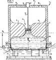
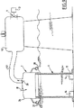
図1は、本発明による第1の実施態様の断面図を示す。
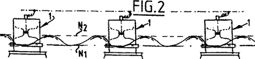
図2は、図1による装置が複数並列された配置(またはアレンジメント)を概略的に示す。
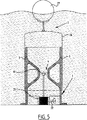
図3は、第2の実施態様の断面図を示す。
図4は、第3の実施態様の断面図を示す。
図5は、第4の実施態様の断面図を示す。
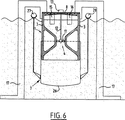
図6は、キャップおよび中空ボディのもう1つの配置を有する第5の実施態様の断面図を示す。
図7は、液圧式増幅器を有する第6の実施態様の断面図である。
図8は、本発明による、フェザーリング羽根(blade feathering)を有する実施態様を示す。
図9は、第7の実施態様の断面図を示す。
図10は、第8の実施態様の断面図を示す。
全ての図面において、中空ボディを1で示し、浮遊ボディを7で示す。
第1の実施態様である図1による装置は、海底2に用いられ、平行な側壁3を有する中空ボディ1からなる。中空ボディ1の内側には、側壁3の間に狭い流路4が設けられている。浮遊ボディ7は、中空ボディ1内の流体10を海水から分離する膜9と流体10それ自身とを含む。
内方向拡張部5、6、中空ボディの壁3、ならびに可撓性膜部材9によって第1の空間が規定される。低い海面N1の間は、膜9は記述の位置にあり、他方、高い海面N2の際には、膜9は矢印Pの方向に移動され、流体10が第1の空間から第2の空間へ上方に動かされる。第2の空間は、中空ボディ1の上部に位置し、内方向拡張部5、6、中空ボディ1の壁3、および中空ボディ1の頂部8によって規定される。狭い流路4によって、流路4内の流体が加速される。流路4を通って移動された流体は、プロペラ11を駆動する。プロペラ11は、シャフト12によって、電気エネルギーを発生させるための発電機13に接続されている。N2からN1へ海面が低下する際には、第2の空間内の流体は、重力によって第1の空間に戻り、再びプロペラ11を駆動する。中空ボディ1の下方の壁3には、海水の入口用の開口部14が設けられている。頂部8には、第2の空間を流体で充填する間に空気を逃がすために、開口部15、16が設けられている。
図2においては、本発明による装置が、海底に並列に立っている。各装置のアウトレット・シャフト(または出力シャフト)は、共通のシャフトに接続されている。
図3による第2の実施態様においては、装置は中空ボディを含む。中空ボディ1の内側には、内方向拡張部分5、6の間に狭い流路4が設けられている。2つの空間24、25が、流路4の両側に設けられている。中空ボディ1の頂部8は、フロート部材27、28に接続されたキャップ26によって覆われている。浮遊ボディ7は、キャップ26とフロート部材27、28を含む。キャップ26には少なくとも1つの開口部15が設けられ、開口部15はふた29によって閉じることができる。捕捉された空気を大気中に排出するために、ふた29は、空気式手段などの作動部材(またはアクチュエーター)30により可動である。共振(または同調)のために、外部の海面の動きが、ボディ1の内部の海面の動きと同じ方向で、かつこれよりも速い場合にのみふた29が閉じられる。フロート部材27、28によりキャップ26に伝達される波の動きによって、キャップ26が上および下に動く場合に、ボディ1の内部でキャップ26と海面との間に捕捉される空気は、それぞれ圧縮および膨張され、よって、海水からなるカラムが流路4を通って流れ、タービン11が駆動する。中空ボディ1の内部の空気の体積を調節するために、ふた29を閉または開にしてよい。
中空ボディ1の下側には、閉鎖可能な開口部14が設けられている。これにより、中空ボディ1の内部の流体カラムの長さが調節可能であり、これにより、その固有振動数は、海水の動きの振動数に調節することができる。
キャップの内部には、水カラムの頂面に関してキャップの動きの速度を測定するために、トランスデューサー34、35が設けられている。
本発明による装置の第3の実施態様を図4に示す。この装置は、海水の入口用の開口部14を残して、脚部17によって海底に立っている中空ボディ1を含む。中空ボディ1の頂部は、キャップ26により封鎖され、キャップ26はフロート部材27、28の動作によって上および下に自由に動き、またフロート部材27、28は海の波によって動く。フロート部材27、28が波上で上方に動くと、これは、キャップ26を中空ボディ1に対して上方に動かす。空気プロペラ11は、キャップ26に取り付けられ、フレーム18によりキャップに支持される発電機13に接続されている。
この構成は、結果的には、2つのスプリングの直列接続である力学系を提供する。キャップ26の下方にて圧縮される空気は、スプリングとして挙動し、中空ボディ1内の水は、アルキメデスの原理の結果としてスプリングのように挙動する。キャップ26が動くと、空気は圧縮および膨張される。これは、次に、中空ボディ1内で水を振動させる。キャップ26の動きの方向にかかわらず、回転が常に同じ方向となるように、プロペラ11にはフェザーリングされ得る羽根が備え付けられる。プロペラ11により付与される減衰(またはダンピング)レベルを、デバイスがうねりの一次周波数(primary frequency)に調和するように、中空ボディ1内の振動する水カラムの流体力学的挙動を最適化しなければならない。
図5は、本発明による装置のもう1つの実施態様を示す。図3の実施態様とは対照的に、この実施態様は、完全に海面下に配置される。フロート部材27の動作の下に、キャップ26が中空ボディ1の側壁3に沿って上および下に動かされる。流路4を通る水のフローがプロペラ11を駆動する。プロペラ11は、ギアボックス21を通じて駆動シャフト22に接続され、また駆動シャフト22は、中空ボディ1からある距離にある、海面より上に位置する発電機を駆動するために噛合されていてもよい。
図6は、キャップ26および中空ボディ1のもう1つの構成を示す。この実施態様において、発電機13は中空ボディ1の頂部8に位置し、キャップ26は下方から動かされる。この場合、中空ボディ1は脚部17により支持される。水は、潮位が最も低い(干潮)ときの海面の直ぐ下に配置されている開口部15、16を通って中空ボディ1の頂部に自由に流入する。
図7には、液圧式増幅器23を用いる実施態様が示される。液圧式増幅器23は、海底に立っている脚部35により支持される。フロート部材27は、ピストン31に接続され、ピストン31は、キャップ26に接続されたピストン32より大きい直径を有する。フロート部材27に接続されたピストン31は、より大きい直径を有する増幅器23の上部33内で動き、キャップ26に接続されたピストン32は、より小さい直径を有する増幅器23の下部34内で動く。キャップ26の動きは、大きい直径と小さい直径との間の比の二乗により得られる増幅度で増幅されることが明白である。
液体すなわち流体10または海水の移動によって駆動されるプロペラを用いる、図1、3、5、6、および7の実施態様は、流路を通る流体フローが逆転したときにプロペラの回転が逆転するという欠点を有する。これは、流体フローの方向に従って羽根をフェザーリングすることができるプロペラを用いることによって回避され得る。
図8は、フェザーリング可能な羽根を有するプロペラ11の可能な実施態様を示す。羽根は示していないが、シャフト37のボディに切られたスロット36に保持される。シャフト37は、プロペラ11のボディ内でピニオン38に取り付けられ、ピニオン38はラック39に交合する。ラック39は、頂部および底部にてプレート40、41に取り付けられ、プレート40、41は、プロペラ駆動シャフト12に沿って上および下に自由に動く。図面を参照して、頂部プレート40が下方に押された場合、ラック39がピニオン38を回転させ、これにより、スロット36が時計回りに90度回転する。これは、羽根が90度回転することを意味する。逆に、底部プレート41が上方に押される場合には、再びスロット36は図示する向きとなる。これらの回転がちょうど流体フローの逆転時に起こると、プロペラ11は一方向に回転し続け、よって、プロペラ11内の慣性力を最小限にする。
流体フローの逆転の問題に対処するもう1つの可能性は、図9のような構成を用いることである。キャップ26には、外気と連通する入口バルブ19と、ダクト43を通じてリザーバー42と連通する出口バルブ20とが設けられている。発電機13に接続されたプロペラ11は、リザーバー42の出口流路に配置される。キャップ26の上方へのストロークの際には、出口バルブ20は閉じたままで、入口バルブ19を通じて空気を吸引する。下方のストロークの際には、キャップ26の下方の空気がダクト43を通じてリザーバー42に移されるように、出口バルブ20が開き、入口バルブ19が閉じる。リザーバー内の空気は、フェザーリング可能な羽根を要しないプロペラ11を駆動するのに使用される。
図10の実施態様では、リザーバー42は、キャップ26の下方に好都合に設けられる。この実施態様の機能は、図9の実施態様の機能に似ているが、空気が、キャップ26の下方のリザーバー42に貯蔵され、キャップ26に取り付けられたプロペラ11を駆動する点で異なる。
キャップ26を用いる実施態様では、キャップ26は自由に回転し、手段は、フロート部材27、28が到来する波の前部(incoming wave front)に面し得るように、キャップ26を自動的に位置付けるために用いられ得る。
海面のうねりを強制的に起こすために風車を据え付けることが更に可能であることに留意されたい。これは、海が比較的穏やかであり、これに対して風が強いという状況下で用いることができる。風のエネルギーを水の波に変換することは、例えばジェット気流を海面に吹き付けるなどの任意の適切な手段によって行うことができる。The present invention is a hollow body used substantially upright on the sea floor, the wall having at least one opening so that water can freely enter or leave the hollow body. The present invention relates to an apparatus for converting energy from vertical movement of seawater, including a hollow body.
Seawater motion due to waves, swells, and tides is used in many known proposals to convert that energy.
The object of the present invention is to improve this device.
This is a floating body (or a floating body) that is movable with respect to the hollow body in the vertical direction by the movement of the sea surface, and communicates with the space in the hollow body and changes its volume. This is achieved by a device that converts the energy from the vertical movement of seawater with a floating body.
As the volume of the hollow body increases and decreases, fluid flow is introduced into the hollow body. This fluid flow is used to drive a propeller connected directly or indirectly to the energy generating means.
The hollow body preferably has parallel side walls and the floating body includes a cap-like member for sealing the top or bottom opening. The cap-like member moves up and down along with the vertical movement of the seawater along the side wall of the hollow body.
According to one embodiment of the invention, the cap is provided with valve means in communication with the outside air, the outlet is disposed in the cap, the outlet is provided with valve means, the outlet is in communication with the air reservoir, The air reservoir is in communication with a propeller connected to the energy generating means. In this embodiment, the fluid flow introduced into the hollow body includes a liquid flow as well as an air flow, which is used to drive the propeller.
In a preferred embodiment, a reservoir is disposed on the cap.
Fluid flow acceleration is obtained when the hollow body is provided with a narrow channel between the side walls.
In another embodiment of the present invention, a propeller connected to the energy generating means is provided in the flow path. In this embodiment, the fluid flow drives the propeller directly. Due to the acceleration of the fluid in the flow path, the possibility of driving the propeller is optimally utilized.
When the cap is located above the sea level, the cap is provided with at least one opening. In this manner, air trapped below the cap can be discharged into the atmosphere. The cap may be provided with a lid that fits into the opening or the respective opening, and the lid is actuated by pneumatic means. If desired, the lid can be lifted from the opening to expel the trapped air.
Preferably, the floating body includes a cap and at least one float member connected to the cap. The cap moves up and down by movement of the float member.
The effect of sea movement transmitted to the cap by the float member is a hydraulic amplifier comprising two pistons / cylinders with different diameters, one piston connected to the float member and the other piston connected to the cap It may be amplified by a hydraulic amplifier.
In some embodiments, to obtain unidirectional rotation of the propeller, the propeller blades are feathered (or the blade angle can be varied) according to the direction of fluid flow within the hollow body.
In a preferred embodiment, the vanes are fitted on a shaft attached to a pinion that mates with the rack, which rack is attached to the actuating means. In this way, the blades can be pivoted to the appropriate angular position to rotate the propeller in one direction regardless of the direction of fluid flow.
In a preferred embodiment, the actuating means is formed by a plate arranged perpendicular to the fluid flow inside the hollow body at the top and / or bottom of the propeller. The force of fluid flow in the flow path pushes the propeller blades in the correct direction.
In another embodiment of the invention, the floating body includes a membrane that separates the fluid in the hollow body from the seawater, the fluid itself having a lower density than the seawater. According to this embodiment, a movable member that requires guidance (or guide) is not used.
In this embodiment, the fluid type and volume as well as the hollow body so that the fluid vibrates at its own natural frequency (resonant) at a given frequency of vertical movement of the sea surface. A shape is selected. The amplitude of the vibration of the fluid in the hollow body is maximized when the vibration frequency of the sea surface matches the natural frequency of the fluid.
According to the present invention, it is possible to connect outputs (or outputs) of a plurality of devices arranged in parallel to a common shaft.
The present invention will be described with reference to the accompanying drawings.
FIG. 1 shows a cross-sectional view of a first embodiment according to the present invention.
FIG. 2 schematically shows an arrangement (or arrangement) in which a plurality of devices according to FIG. 1 are arranged in parallel.
FIG. 3 shows a cross-sectional view of the second embodiment.
FIG. 4 shows a cross-sectional view of the third embodiment.
FIG. 5 shows a cross-sectional view of the fourth embodiment.
FIG. 6 shows a cross-sectional view of a fifth embodiment with another arrangement of cap and hollow body.
FIG. 7 is a cross-sectional view of a sixth embodiment having a hydraulic amplifier.
FIG. 8 shows an embodiment with feather feathering according to the present invention.
FIG. 9 shows a cross-sectional view of the seventh embodiment.
FIG. 10 shows a cross-sectional view of the eighth embodiment.
In all the drawings, the hollow body is denoted by 1 and the floating body is denoted by 7.
The device according to FIG. 1 which is a first embodiment consists of a
A first space is defined by the inwardly extending portions 5, 6, the hollow body wall 3, and the flexible membrane member 9. During the low sea level N1, the membrane 9 is in the position described, while at the high sea level N2, the membrane 9 is moved in the direction of the arrow P and the
In FIG. 2, the device according to the invention stands in parallel on the seabed. The outlet shaft (or output shaft) of each device is connected to a common shaft.
In a second embodiment according to FIG. 3, the device comprises a hollow body. Inside the
On the lower side of the
Inside the cap,
A third embodiment of the device according to the invention is shown in FIG. This device comprises a
This configuration results in a dynamic system that is a series connection of two springs. The air compressed under the
FIG. 5 shows another embodiment of the device according to the invention. In contrast to the embodiment of FIG. 3, this embodiment is located completely below sea level. Under the action of the
FIG. 6 shows another configuration of the
FIG. 7 shows an embodiment using a
The embodiments of FIGS. 1, 3, 5, 6, and 7 that use propellers driven by the movement of liquid or fluid 10 or seawater say that the rotation of the propeller is reversed when the fluid flow through the flow path is reversed. Has drawbacks. This can be avoided by using a propeller that can feather the vanes according to the direction of fluid flow.
FIG. 8 shows a possible embodiment of the
Another possibility to deal with the problem of fluid flow reversal is to use a configuration like that of FIG. The
In the embodiment of FIG. 10, the
In embodiments using the
Note that it is further possible to install a windmill to force sea level swells. This can be used in situations where the sea is relatively calm and winds are strong. Converting wind energy into water waves can be done by any suitable means such as, for example, blowing a jet stream against the sea surface.
Claims (15)
海底(2)に実質的に直立して用いられる中空ボディ(1)であって、水が中空ボディ(1)に自由に出入りして移動するように、その壁に少なくとも1つの開口部(14)が設けられている中空ボディ(1)と、
海面の動きにより鉛直方向に該中空ボディ(1)に対して可動である浮遊ボディ(7)と、
エネルギー発生手段(13)に接続されたプロペラ(11)と
を含み、中空ボディ(1)に対して浮遊ボディ(7)が動くことによって中空ボディ(1)の体積が変化し、これにより、中空ボディ(1)の内部に流体フローを起こしてプロペラ(11)が駆動され、および、該中空ボディ(1)が平行な側壁(3)を有し、該浮遊ボディ(7)が、その頂部または底部の開口部を閉鎖するためのキャップ様部材(26)を含むことを特徴とする装置。 A device that converts energy from the vertical movement of seawater,
A hollow body (1) used substantially upright on the seabed (2), the wall having at least one opening (14) so that water can freely enter and exit the hollow body (1). A hollow body (1) provided with
A floating body (7) movable relative to the hollow body (1) in the vertical direction by movement of the sea surface;
A propeller (11) connected to the energy generating means (13);
The volume of the hollow body (1) is changed by the movement of the floating body (7) relative to the hollow body (1), thereby causing a fluid flow inside the hollow body (1) and causing the propeller (11 ) is driven, and, the hollow body (1) has parallel side walls (3), the cap-like member for the floating body (7) for closing the opening of the top or bottom (26) equipment characterized in that it comprises.
海底(2)に実質的に直立して用いられる中空ボディ(1)であって、水が中空ボディ(1)に自由に出入りして移動するように、その壁に少なくとも1つの開口部(14)が設けられている中空ボディ(1)と、
海面の動きにより鉛直方向に該中空ボディ(1)に対して可動である浮遊ボディ(7)と、
エネルギー発生手段(13)に接続されたプロペラ(11)と
を含み、中空ボディ(1)に対して浮遊ボディ(7)が動くことによって中空ボディ(1)の体積が変化し、これにより、中空ボディ(1)の内部に流体フローを起こしてプロペラ(11)が駆動され、および、該浮遊ボディ(7)が膜(9)を含み、膜(9)は、該中空ボディ(1)内で海水から流体(10)を分離し、該流体自身は、海水より低い密度を有することを特徴とする装置。 A device that converts energy from the vertical movement of seawater,
A hollow body (1) used substantially upright on the seabed (2), the wall having at least one opening (14) so that water can freely enter and exit the hollow body (1). A hollow body (1) provided with
A floating body (7) movable relative to the hollow body (1) in the vertical direction by movement of the sea surface;
A propeller (11) connected to the energy generating means (13);
The volume of the hollow body (1) is changed by the movement of the floating body (7) relative to the hollow body (1), thereby causing a fluid flow inside the hollow body (1) and causing the propeller (11 ) is driven, and includes the floating body (7) membrane (9), film (9) separates the fluid (10) from the seawater in the hollow body (1) within the fluid itself, equipment characterized by having a lower density than seawater.
Applications Claiming Priority (3)
| Application Number | Priority Date | Filing Date | Title |
|---|---|---|---|
| NL1005542 | 1997-03-14 | ||
| NL1005542A NL1005542C2 (en) | 1997-03-14 | 1997-03-14 | Device for the conversion of energy from the vertical movement of sea water. |
| PCT/EP1998/001571 WO1998041758A1 (en) | 1997-03-14 | 1998-03-11 | Apparatus for conversion of energy from the vertical movement of seawater |
Publications (3)
| Publication Number | Publication Date |
|---|---|
| JP2001516416A JP2001516416A (en) | 2001-09-25 |
| JP2001516416A5 JP2001516416A5 (en) | 2005-10-06 |
| JP4229473B2 true JP4229473B2 (en) | 2009-02-25 |
Family
ID=19764607
Family Applications (1)
| Application Number | Title | Priority Date | Filing Date |
|---|---|---|---|
| JP54014098A Expired - Lifetime JP4229473B2 (en) | 1997-03-14 | 1998-03-11 | A device that converts energy from vertical movement of seawater |
Country Status (17)
| Country | Link |
|---|---|
| US (1) | US6216455B1 (en) |
| EP (1) | EP1007843B1 (en) |
| JP (1) | JP4229473B2 (en) |
| KR (1) | KR100549736B1 (en) |
| CN (1) | CN1097159C (en) |
| AT (1) | ATE251716T1 (en) |
| AU (1) | AU728906B2 (en) |
| BR (1) | BR9808006A (en) |
| CA (1) | CA2283898C (en) |
| DE (1) | DE69818838T2 (en) |
| DK (1) | DK1007843T3 (en) |
| ES (1) | ES2203945T3 (en) |
| HK (1) | HK1026468A1 (en) |
| IL (1) | IL131764A0 (en) |
| NL (1) | NL1005542C2 (en) |
| PT (1) | PT1007843E (en) |
| WO (1) | WO1998041758A1 (en) |
Families Citing this family (62)
| Publication number | Priority date | Publication date | Assignee | Title |
|---|---|---|---|---|
| GB9804770D0 (en) * | 1998-03-07 | 1998-04-29 | Engineering Business Ltd | Apparatus for extracting power from moving water |
| IT1306619B1 (en) * | 1998-11-11 | 2001-06-18 | Paolo Boccotti | "WELL" SYSTEM FOR THE EXPLOITATION OF THE ENERGY OF THE DELMARE WAVES. |
| NL1015196C2 (en) * | 2000-05-12 | 2001-11-19 | Zakaria Khalil Doleh | Device for storing potential energy. |
| DE10028431A1 (en) * | 2000-06-13 | 2002-03-07 | Nicolas Chatzigrigoriou | Hydroelectric power station |
| WO2002090768A1 (en) | 2001-05-04 | 2002-11-14 | Brumfield Donald U | Tidal/wave compressed air electricity generation |
| FR2826066A1 (en) | 2001-06-19 | 2002-12-20 | Jean Pierre Tromelin | Device for regulating windmill blade rotation comprises flap articulated around axis parallel to blade longitudinal axis able to open between positions in plane perpendicular to blade and retracted in blade |
| ES2291525T3 (en) * | 2002-01-10 | 2008-03-01 | Seabased Ab | A SMALL UNIT AND THE USE OF A SMALL UNIT FOR THE PRODUCTION OF ELECTRICAL ENERGY, A METHOD FOR GENERATING ELECTRICAL ENERGY AND A COMPONENT SYSTEM FOR MANUFACTURING A LINEAR GENERATOR FOR A SMALL UNIT. |
| US6747363B2 (en) * | 2002-02-02 | 2004-06-08 | Gines Sanchez Gomez | Floating platform harvesting sea wave energy for electric power generation |
| NO20030491L (en) * | 2003-01-31 | 2004-08-02 | Paul K Morch | Apparatus at an electric power plant. |
| US7003955B2 (en) * | 2003-08-15 | 2006-02-28 | Lester Davis | Enhanced pumped storage power system |
| JP2007508488A (en) * | 2003-10-14 | 2007-04-05 | ウェーブ・スター・エナジー・アンパルトセルスカブ | Wave generator with float and means for fixing float above sea level |
| NL1027469C2 (en) | 2004-11-10 | 2006-05-17 | Zakaria Khalil Doleh | Method and device for generating energy from a movement of a medium such as sea water. |
| GB0501873D0 (en) * | 2005-01-29 | 2005-03-09 | Palmer Bruce W | Wave energy converter |
| AU2005335643A1 (en) * | 2005-08-15 | 2007-02-22 | Andrew Cassius Evans | The ocean wave energy converter (OWEC) |
| US7498685B2 (en) * | 2005-11-09 | 2009-03-03 | Timothy John Emmanuel Turner | Electrical generator |
| US7355298B2 (en) * | 2006-03-17 | 2008-04-08 | Glen Edward Cook | Syphon wave generator |
| GB2440344A (en) * | 2006-07-26 | 2008-01-30 | Christopher Freeman | Impulse turbine design |
| US7579705B1 (en) | 2006-10-04 | 2009-08-25 | Ross Anthony C | System and method for generating electrical energy using a floating dock |
| GB0715569D0 (en) * | 2007-08-09 | 2007-09-19 | Turner Gordon H | Wave power conversion |
| US8084873B2 (en) * | 2008-01-07 | 2011-12-27 | Carter Richard W | Induced surface flow wave energy converter |
| US8207622B2 (en) * | 2008-02-20 | 2012-06-26 | Knowledge Based Systems, Inc. | Inertial mass power generation |
| US20100283248A1 (en) * | 2009-02-20 | 2010-11-11 | Moffat Brian L | Venturi based ocean wave energy conversion system |
| US8925313B2 (en) * | 2008-02-22 | 2015-01-06 | Brian Lee Moffat | Wave energy conversion apparatus |
| AU2008361028B2 (en) * | 2008-08-29 | 2013-03-28 | Hann-Ocean Energy Pte. Ltd. | Device for conversion of wave energy |
| US20100171313A1 (en) * | 2009-01-08 | 2010-07-08 | Glen Edward Cook | Under the bottom ocean wave energy converter |
| DE102009008211B4 (en) * | 2009-02-10 | 2016-06-02 | Sinn Power Gmbh | Energy production from waves or pulses |
| CN101956647B (en) * | 2009-07-15 | 2012-12-19 | 鸿富锦精密工业(深圳)有限公司 | Tidal power generating device |
| US7830032B1 (en) * | 2009-08-28 | 2010-11-09 | Breen Joseph G | Generating power from natural waves in a body of water |
| US8286425B2 (en) | 2009-10-23 | 2012-10-16 | Dresser-Rand Company | Energy conversion system with duplex radial flow turbine |
| US8698338B2 (en) * | 2010-03-08 | 2014-04-15 | Massachusetts Institute Of Technology | Offshore energy harvesting, storage, and power generation system |
| CN103109081B (en) | 2010-07-16 | 2018-01-02 | 克尔鲍尔海洋股份公司 | Energy conversion unit and the energy conversion system including the unit |
| CN102062041A (en) * | 2011-01-29 | 2011-05-18 | 浙江大学 | Surfing-type wave generating device and method |
| CN202468149U (en) * | 2011-08-25 | 2012-10-03 | 陈文彬 | Water-turbine-type seawave generating equipment |
| DE102011116033B4 (en) * | 2011-10-17 | 2015-06-03 | Silke Brandl | Apparatus for generating energy |
| ES2456190B1 (en) * | 2012-09-17 | 2015-02-11 | Manuel Grases Galofre | POWER DEVICE AND GENERATOR DEVICE FROM LAS OLAS |
| FI20135402L (en) * | 2013-04-19 | 2014-10-20 | Subsea Energy Oy | Hybrid power plant |
| CN104863778A (en) * | 2014-02-24 | 2015-08-26 | 钟炽昌 | Wind power and water power generator |
| CN104005904B (en) * | 2014-05-16 | 2017-01-11 | 东北师范大学 | Shore-based energy collecting type wave energy power generation device |
| CN104005903B (en) * | 2014-05-20 | 2017-02-15 | 华南理工大学 | Vertical-axis wave-activated generator |
| CN104314741A (en) * | 2014-10-09 | 2015-01-28 | 长沙理工大学 | Double-floating-body type wave energy power generation device utilizing water turbine |
| JP6061980B2 (en) * | 2015-04-20 | 2017-01-18 | モファット,ブライアン,リー | Wave energy equipment |
| SE540263C2 (en) * | 2016-06-13 | 2018-05-15 | Novige Ab | Apparatus for harvesting energy from waves |
| US10385820B2 (en) * | 2016-08-22 | 2019-08-20 | Brian Lee Moffat | Wave energy device with constricted tube and generator pod |
| RU174403U1 (en) * | 2017-01-09 | 2017-10-11 | Муниципальное бюджетное общеобразовательное учреждение "Лицей N 145" Авиастроительного района города Казани | WAVE POWER INSTALLATION |
| CN107842459B (en) * | 2017-11-08 | 2023-05-12 | 大连理工大学 | Wave energy conversion device combined by oscillating water column and oscillating floater |
| US10634113B2 (en) * | 2018-01-03 | 2020-04-28 | Lone Gull Holdings, Ltd. | Inertial water column wave energy converter |
| US10989164B2 (en) * | 2018-03-05 | 2021-04-27 | Richard W. Carter | Resonant unidirectional wave energy converter |
| CN108412680A (en) * | 2018-03-13 | 2018-08-17 | 浙江海洋大学 | Wave energy converting device |
| WO2020014729A1 (en) * | 2018-07-16 | 2020-01-23 | Eamon Bergin | Wave powered generator |
| CN109538402A (en) * | 2018-10-30 | 2019-03-29 | 贵州航天天马机电科技有限公司 | A kind of unlimited pole combination circular cone float type wave energy power generation |
| US10837420B2 (en) | 2018-10-31 | 2020-11-17 | Loubert S. Suddaby | Wave energy capture device and energy storage system utilizing a variable mass, variable radius concentric ring flywheel |
| US10788011B2 (en) | 2018-10-31 | 2020-09-29 | Loubert S. Suddaby | Wave energy capture device and energy storage system utilizing a variable mass, variable radius concentric ring flywheel |
| US20200271087A1 (en) * | 2019-02-23 | 2020-08-27 | Lone Gull Holdings, Ltd. | Wave-energized diode pump |
| CN111156129B (en) * | 2020-01-15 | 2020-12-11 | 长沙理工大学 | Wave current power generation device suitable for coral reef terrain |
| CN111550357B (en) * | 2020-05-13 | 2022-05-20 | 杭州巨浪能源科技有限公司 | Wave energy power generation equipment |
| US11566610B2 (en) | 2020-05-14 | 2023-01-31 | Ghazi Khan | Wave-powered generator |
| US11208980B1 (en) * | 2021-03-01 | 2021-12-28 | University Of North Florida Board Of Trustees | Integrated system for optimal continuous extraction of potential energy derived from waves |
| CN113479294A (en) * | 2021-06-23 | 2021-10-08 | 李奕权 | Sea wave energy conversion device for sea wave power generation and floating platform |
| CN113882992B (en) * | 2021-09-28 | 2024-04-12 | 江苏科技大学 | Floating wave-absorbing and power-generating integrated device based on internal cavity water wave resonance |
| CN114352468A (en) * | 2021-11-04 | 2022-04-15 | 赖国民 | Super high-efficiency power generation device utilizing tidal pressure |
| CN115013231A (en) * | 2022-05-18 | 2022-09-06 | 中国科学院广州能源研究所 | Pneumatic wave energy power supply submerged buoy |
| EP4296503A1 (en) | 2022-06-24 | 2023-12-27 | OctoMar ApS | A wave energy power generation system |
Family Cites Families (26)
| Publication number | Priority date | Publication date | Assignee | Title |
|---|---|---|---|---|
| US875042A (en) * | 1906-05-21 | 1907-12-31 | Edward J Bissell | Wave-motor. |
| US1623341A (en) * | 1921-08-17 | 1927-04-05 | Charles N Hare | Ocean compressed-air power |
| US3391903A (en) * | 1967-08-04 | 1968-07-09 | Charles A. Peterson Jr. | Power generating apparatus |
| SE373639B (en) * | 1973-06-18 | 1975-02-10 | M W Gustafson | DEVICE FOR UTILIZING ENERGY BOUND IN THE WATER MOVEMENT OR SEWING |
| US3870893A (en) * | 1973-10-15 | 1975-03-11 | Henry A Mattera | Wave operated power plant |
| US4286347A (en) * | 1974-07-22 | 1981-09-01 | Tideland Signal Corporation | Double acting turbine for converting wave energy of water to electrical power |
| GB1587433A (en) * | 1976-09-16 | 1981-04-01 | Loqvist K R | Apparatus for utilizing kinetic energy stored in the swell or wave movement of water |
| GB1595700A (en) * | 1976-11-13 | 1981-08-12 | Univ Belfast | Fluid driven rotary transducer |
| US4123667A (en) * | 1977-03-28 | 1978-10-31 | Decker Bert J | Wave energy generator-breakwater-barge-dock |
| US4138845A (en) * | 1977-07-29 | 1979-02-13 | Seiichi Kitabayashi | Reciprocating motors |
| GB1574379A (en) * | 1977-08-24 | 1980-09-03 | English Electric Co Ltd | Turbines and like rotary machines |
| FR2449800A1 (en) * | 1979-02-21 | 1980-09-19 | Liautaud Jean | Wave powered submerged electric generator - has vertically moving piston driving current of water past turbine and generator |
| NO145548C (en) * | 1979-04-19 | 1982-04-14 | Kvaerner Brug Kjoleavdelning | BOELGEKRAFTVERK |
| US4271668A (en) * | 1979-10-17 | 1981-06-09 | Mccormick Michael E | Counter-rotating wave energy conversion turbine |
| US4365937A (en) * | 1979-11-26 | 1982-12-28 | Hiebert Harold L | Adjustable pitch propeller drive |
| ES8100703A1 (en) * | 1980-01-31 | 1980-11-01 | Hermenegil Sendra Zurita | Electrical power station driven by wave energy |
| DE3172265D1 (en) * | 1980-12-01 | 1985-10-17 | Secretary Energy Brit | Device for extracting energy from waves |
| CH660770A5 (en) * | 1981-06-05 | 1987-06-15 | Escher Wyss Ag | Turbine |
| US4594853A (en) * | 1984-03-12 | 1986-06-17 | Wave Power Industries | Wave powered generator |
| JPS6241974A (en) * | 1984-11-30 | 1987-02-23 | Koichi Nishikawa | Wave-power generating set |
| US4883411A (en) * | 1988-09-01 | 1989-11-28 | Windle Tom J | Wave powered pumping apparatus and method |
| US4914915A (en) * | 1989-06-20 | 1990-04-10 | Linderfelt Hal R | Wave powered turbine |
| US5186822A (en) * | 1991-02-25 | 1993-02-16 | Ocean Resources Engineering, Inc. | Wave powered desalination apparatus with turbine-driven pressurization |
| GB9108152D0 (en) * | 1991-04-17 | 1991-06-05 | Applied Res & Tech | Wave energy converter |
| US5374850A (en) * | 1993-09-29 | 1994-12-20 | Cowen; Hal C. | Apparatus and method for tidal and wave generation of power |
| US5770893A (en) * | 1994-04-08 | 1998-06-23 | Youlton; Rodney Graham | Wave energy device |
-
1997
- 1997-03-14 NL NL1005542A patent/NL1005542C2/en not_active IP Right Cessation
-
1998
- 1998-03-11 US US09/381,015 patent/US6216455B1/en not_active Expired - Lifetime
- 1998-03-11 DE DE69818838T patent/DE69818838T2/en not_active Expired - Lifetime
- 1998-03-11 AU AU72078/98A patent/AU728906B2/en not_active Expired
- 1998-03-11 BR BR9808006-7A patent/BR9808006A/en not_active IP Right Cessation
- 1998-03-11 KR KR1019997008084A patent/KR100549736B1/en not_active IP Right Cessation
- 1998-03-11 CN CN98803355A patent/CN1097159C/en not_active Expired - Lifetime
- 1998-03-11 IL IL13176498A patent/IL131764A0/en not_active IP Right Cessation
- 1998-03-11 WO PCT/EP1998/001571 patent/WO1998041758A1/en active IP Right Grant
- 1998-03-11 CA CA002283898A patent/CA2283898C/en not_active Expired - Lifetime
- 1998-03-11 JP JP54014098A patent/JP4229473B2/en not_active Expired - Lifetime
- 1998-03-11 ES ES98919110T patent/ES2203945T3/en not_active Expired - Lifetime
- 1998-03-11 AT AT98919110T patent/ATE251716T1/en active
- 1998-03-11 EP EP98919110A patent/EP1007843B1/en not_active Expired - Lifetime
- 1998-03-11 DK DK98919110T patent/DK1007843T3/en active
- 1998-03-11 PT PT98919110T patent/PT1007843E/en unknown
-
2000
- 2000-09-15 HK HK00105819A patent/HK1026468A1/en not_active IP Right Cessation
Also Published As
| Publication number | Publication date |
|---|---|
| AU7207898A (en) | 1998-10-12 |
| ATE251716T1 (en) | 2003-10-15 |
| HK1026468A1 (en) | 2000-12-15 |
| CA2283898C (en) | 2007-05-29 |
| ES2203945T3 (en) | 2004-04-16 |
| EP1007843A1 (en) | 2000-06-14 |
| JP2001516416A (en) | 2001-09-25 |
| DK1007843T3 (en) | 2003-11-03 |
| WO1998041758A1 (en) | 1998-09-24 |
| CA2283898A1 (en) | 1998-09-24 |
| BR9808006A (en) | 2000-03-08 |
| DE69818838T2 (en) | 2004-09-09 |
| EP1007843B1 (en) | 2003-10-08 |
| NL1005542C2 (en) | 1998-09-15 |
| CN1097159C (en) | 2002-12-25 |
| KR20000075998A (en) | 2000-12-26 |
| IL131764A0 (en) | 2001-03-19 |
| US6216455B1 (en) | 2001-04-17 |
| DE69818838D1 (en) | 2003-11-13 |
| KR100549736B1 (en) | 2006-02-08 |
| CN1250507A (en) | 2000-04-12 |
| PT1007843E (en) | 2004-02-27 |
| AU728906B2 (en) | 2001-01-18 |
Similar Documents
| Publication | Publication Date | Title |
|---|---|---|
| JP4229473B2 (en) | A device that converts energy from vertical movement of seawater | |
| KR20010041580A (en) | Extracting power from moving water | |
| US7322189B2 (en) | Wide bandwidth farms for capturing wave energy | |
| JP6502933B2 (en) | Vertical movement buoy point absorber | |
| JP4831921B2 (en) | Device for storing potential energy | |
| JPS6211188B2 (en) | ||
| GB2532074A (en) | Wave power converter | |
| JP2011074854A (en) | Turbine for wave power generation | |
| US4753070A (en) | Apparatus utilized in generating power and method for revolving a plurality of vanes to generate power | |
| WO2009096796A2 (en) | Wave energy device | |
| MXPA99008355A (en) | Apparatus for conversion of energy from the vertical movement of seawater | |
| GB1601219A (en) | Devices for extracting energy from wave power | |
| US10400741B2 (en) | Dynamic turning of wave energy converters using inertial traps | |
| US20080272601A1 (en) | Electrical energy from naturally moving fluids | |
| WO2022093909A1 (en) | Buoy with radiated wave reflector | |
| WO2012015337A1 (en) | Floating element of a wave station | |
| IE48492B1 (en) | Energy generating device | |
| JP2002048049A (en) | Wave power plant |
Legal Events
| Date | Code | Title | Description |
|---|---|---|---|
| A521 | Request for written amendment filed |
Free format text: JAPANESE INTERMEDIATE CODE: A523 Effective date: 20050125 |
|
| A621 | Written request for application examination |
Free format text: JAPANESE INTERMEDIATE CODE: A621 Effective date: 20050125 |
|
| A131 | Notification of reasons for refusal |
Free format text: JAPANESE INTERMEDIATE CODE: A131 Effective date: 20070508 |
|
| A521 | Request for written amendment filed |
Free format text: JAPANESE INTERMEDIATE CODE: A523 Effective date: 20070723 |
|
| A131 | Notification of reasons for refusal |
Free format text: JAPANESE INTERMEDIATE CODE: A131 Effective date: 20080108 |
|
| A521 | Request for written amendment filed |
Free format text: JAPANESE INTERMEDIATE CODE: A523 Effective date: 20080402 |
|
| TRDD | Decision of grant or rejection written | ||
| A01 | Written decision to grant a patent or to grant a registration (utility model) |
Free format text: JAPANESE INTERMEDIATE CODE: A01 Effective date: 20081104 |
|
| A01 | Written decision to grant a patent or to grant a registration (utility model) |
Free format text: JAPANESE INTERMEDIATE CODE: A01 |
|
| A61 | First payment of annual fees (during grant procedure) |
Free format text: JAPANESE INTERMEDIATE CODE: A61 Effective date: 20081202 |
|
| R150 | Certificate of patent or registration of utility model |
Free format text: JAPANESE INTERMEDIATE CODE: R150 |
|
| FPAY | Renewal fee payment (event date is renewal date of database) |
Free format text: PAYMENT UNTIL: 20111212 Year of fee payment: 3 |
|
| FPAY | Renewal fee payment (event date is renewal date of database) |
Free format text: PAYMENT UNTIL: 20111212 Year of fee payment: 3 |
|
| FPAY | Renewal fee payment (event date is renewal date of database) |
Free format text: PAYMENT UNTIL: 20121212 Year of fee payment: 4 |
|
| FPAY | Renewal fee payment (event date is renewal date of database) |
Free format text: PAYMENT UNTIL: 20121212 Year of fee payment: 4 |
|
| FPAY | Renewal fee payment (event date is renewal date of database) |
Free format text: PAYMENT UNTIL: 20131212 Year of fee payment: 5 |
|
| R250 | Receipt of annual fees |
Free format text: JAPANESE INTERMEDIATE CODE: R250 |
|
| R250 | Receipt of annual fees |
Free format text: JAPANESE INTERMEDIATE CODE: R250 |
|
| R250 | Receipt of annual fees |
Free format text: JAPANESE INTERMEDIATE CODE: R250 |
|
| R250 | Receipt of annual fees |
Free format text: JAPANESE INTERMEDIATE CODE: R250 |
|
| R250 | Receipt of annual fees |
Free format text: JAPANESE INTERMEDIATE CODE: R250 |
|
| EXPY | Cancellation because of completion of term |