JP4229442B2 - Method for producing a tube made of quartz glass, tubular intermediate product made of porous quartz glass, and use thereof - Google Patents
Method for producing a tube made of quartz glass, tubular intermediate product made of porous quartz glass, and use thereof Download PDFInfo
- Publication number
- JP4229442B2 JP4229442B2 JP2003540095A JP2003540095A JP4229442B2 JP 4229442 B2 JP4229442 B2 JP 4229442B2 JP 2003540095 A JP2003540095 A JP 2003540095A JP 2003540095 A JP2003540095 A JP 2003540095A JP 4229442 B2 JP4229442 B2 JP 4229442B2
- Authority
- JP
- Japan
- Prior art keywords
- density
- soot
- tube
- quartz glass
- region
- Prior art date
- Legal status (The legal status is an assumption and is not a legal conclusion. Google has not performed a legal analysis and makes no representation as to the accuracy of the status listed.)
- Expired - Lifetime
Links
Images


Classifications
-
- C—CHEMISTRY; METALLURGY
- C03—GLASS; MINERAL OR SLAG WOOL
- C03B—MANUFACTURE, SHAPING, OR SUPPLEMENTARY PROCESSES
- C03B37/00—Manufacture or treatment of flakes, fibres, or filaments from softened glass, minerals, or slags
- C03B37/01—Manufacture of glass fibres or filaments
- C03B37/012—Manufacture of preforms for drawing fibres or filaments
- C03B37/014—Manufacture of preforms for drawing fibres or filaments made entirely or partially by chemical means, e.g. vapour phase deposition of bulk porous glass either by outside vapour deposition [OVD], or by outside vapour phase oxidation [OVPO] or by vapour axial deposition [VAD]
- C03B37/01413—Reactant delivery systems
- C03B37/0142—Reactant deposition burners
-
- C—CHEMISTRY; METALLURGY
- C03—GLASS; MINERAL OR SLAG WOOL
- C03B—MANUFACTURE, SHAPING, OR SUPPLEMENTARY PROCESSES
- C03B19/00—Other methods of shaping glass
- C03B19/14—Other methods of shaping glass by gas- or vapour- phase reaction processes
- C03B19/1415—Reactant delivery systems
- C03B19/1423—Reactant deposition burners
-
- C—CHEMISTRY; METALLURGY
- C03—GLASS; MINERAL OR SLAG WOOL
- C03B—MANUFACTURE, SHAPING, OR SUPPLEMENTARY PROCESSES
- C03B2207/00—Glass deposition burners
- C03B2207/36—Fuel or oxidant details, e.g. flow rate, flow rate ratio, fuel additives
-
- C—CHEMISTRY; METALLURGY
- C03—GLASS; MINERAL OR SLAG WOOL
- C03B—MANUFACTURE, SHAPING, OR SUPPLEMENTARY PROCESSES
- C03B2207/00—Glass deposition burners
- C03B2207/60—Relationship between burner and deposit, e.g. position
- C03B2207/62—Distance
-
- C—CHEMISTRY; METALLURGY
- C03—GLASS; MINERAL OR SLAG WOOL
- C03B—MANUFACTURE, SHAPING, OR SUPPLEMENTARY PROCESSES
- C03B2207/00—Glass deposition burners
- C03B2207/60—Relationship between burner and deposit, e.g. position
- C03B2207/66—Relative motion
Description
本発明は 、シリコン含有出発成分を火炎加水分解することによって石英ガラス管を製造する方法であって、該出発成分が、SiO2含有粒子を製造するデポジション・バーナーに供給されるという工程と、該粒子が、長軸を中心に回転するキャリア上に堆積されて、所定の径方向密度プロファイルを持つ多孔質SiO2のスート壁を有するスート管を形成する工程と、該スート管が、塩素含有雰囲気中で処理される工程と、該処理されたスート管がガラス化される工程とを含む、方法に関する。 The present invention is a method for producing a quartz glass tube by flame hydrolysis of a silicon-containing starting component, wherein the starting component is fed to a deposition burner for producing SiO 2 -containing particles; The particles are deposited on a carrier that rotates about a major axis to form a soot tube with a porous SiO 2 soot wall having a predetermined radial density profile; and the soot tube contains chlorine The present invention relates to a method including a step of being treated in an atmosphere and a step of vitrifying the treated soot tube.
更に、本発明は、所定の径方向密度プロファイルを持つ多孔質SiO2スート壁を有する石英ガラスから成る管状中間製品、及びこのような管の使用方法に関する。 Furthermore, the invention relates to a tubular intermediate product made of quartz glass with porous SiO 2 soot walls with a predetermined radial density profile and to the use of such a tube.
石英ガラス管は、光ファイバのためのプリフォームの出発原料として使用される。プリフォームは、一般的に、低屈折率を有する材料から成るジャケットで覆われたコアを有する。プリフォームのコアを合成石英ガラスから製造する方法には、VAD(気相軸付け)法、OVD(外付け気相成長)法、MCVD(内付け気相成長)法、及び、PCVD(プラズマ気相成長)法と呼ばれる方法がある。これら全ての方法において、コア・ガラスは、SiO2粒子をサブストレート上に堆積し、ガラス化して製造される。VAD法及びOVD法においては、コア・ガラスは、外側からサブストレート上に堆積され、MCVD法及びPCVD法においては、コア・ガラスはいわゆるサブストレート管の内壁上に堆積される。サブストレート管は、コア材料を純粋に支持する機能を有し得るが、それ自体、導光コアの一部としても形成され得る。繊維設計に応じて、サブストレート管は、ドープ石英ガラス又は非ドープ石英ガラスにより構成される。更に、プリフォームの製造としては、コア・ガラスでできたロッドをクラッド・ガラス管に挿入して、クラッド・ガラスと一緒に溶融させるという、いわゆるロッド・イン・チューブ法が知られている。プリフォームを延伸すると、光ファイバが得られる。 Quartz glass tubes are used as starting materials for preforms for optical fibers. A preform generally has a core covered with a jacket made of a material having a low refractive index. Methods for producing the preform core from synthetic quartz glass include VAD (vapor phase axis), OVD (external vapor phase), MCVD (internal vapor phase), and PCVD (plasma gas). There is a method called a phase growth method. In all these methods, the core glass, SiO 2 is deposited particles on a substrate, is manufactured by vitrification. In the VAD method and the OVD method, the core glass is deposited on the substrate from the outside. In the MCVD method and the PCVD method, the core glass is deposited on the inner wall of the so-called substrate tube. The substrate tube may have the function of purely supporting the core material, but may itself be formed as part of the light guide core. Depending on the fiber design, the substrate tube is made of doped or undoped quartz glass. Furthermore, as a preform, a so-called rod-in-tube method is known in which a rod made of core glass is inserted into a clad glass tube and melted together with the clad glass. When the preform is stretched, an optical fiber is obtained.
各プロセスにもよるが、クラッド・ガラスは、別の方法(OVD法、プラズマ法、ロッド・イン・チューブ法)で製造されたり、あるいは、いわゆるVAD法では一般的であるように、クラッド・ガラス及びコア・ガラスが同時に製造される。コア・ガラスとクラッド・ガラスの屈折率の差は、適切なドーパントを混合することにより設定される。多くのドーパント、特に、ゲルマニウム、燐、又はチタンが、石英ガラスの屈折率を増加させるのに適切であり、一方、フッ素及びホウ素は、石英ガラスの屈折率を減少させるということが知られている。 Depending on each process, the clad glass is manufactured by another method (OVD method, plasma method, rod-in-tube method) or, as is common in the so-called VAD method, the clad glass is used. And the core glass are produced simultaneously. The difference in refractive index between the core glass and the clad glass is set by mixing an appropriate dopant. Many dopants, particularly germanium, phosphorus, or titanium, are suitable for increasing the refractive index of quartz glass, while fluorine and boron are known to decrease the refractive index of quartz glass. .
また、石英ガラスの屈折率は、塩素によってもわずかに増加される。この塩素の影響は、特に、SiCl4などの塩素含有出発原料から石英ガラスを製造する際や、塩素含有雰囲気中で多孔質の「スート体」を処理する際に、注意しなければならない。例えば、欧州特許公開公報No.604 787では、いわゆる「スート法」によるドープ石英ガラス管の製造が記載されている。スート法では、SiCl4やGeCl4という出発成分をデポジション・バーナーで火炎加水分解することによって粒子が製造され、製造された粒子は長軸を中心に回転するキャリア・ロッド上に層を成して堆積さる。この時、デポジッション・バーナーはキャリア・ロッドに沿って振動しながら往復運動する。このプロセスにおいて、GeO2でドープ処理された多孔質スート壁は、SiO2の粒子から形成される。次に、ドープ処理されていないSiO2のクラッド・ガラス層がその上に堆積される。キャリア・ロッドを除去後、このようにして製造された管状のスート体は、通常、塩素含有雰囲気中で加熱することによって、精製・脱水される。プリフォームを完成するために、更なるクラッド・ガラスで囲まれたいわゆるコア・ロッドは、脱水されたスート体をガラス化(焼結)することによって得られる。光ファイバは、プリフォームから線引きされて作られる。 Also, the refractive index of quartz glass is slightly increased by chlorine. This influence of chlorine must be noted especially when producing quartz glass from a chlorine-containing starting material such as SiCl 4 or when processing a porous “soot body” in a chlorine-containing atmosphere. For example, European Patent Publication No. No. 604 787 describes the production of doped quartz glass tubes by the so-called “soot method”. In the soot method, particles are produced by flame hydrolysis of starting components such as SiCl 4 and GeCl 4 with a deposition burner, and the produced particles are layered on a carrier rod that rotates about the long axis. It accumulates. At this time, the deposition burner reciprocates while vibrating along the carrier rod. In this process, a porous soot wall doped with GeO 2 is formed from particles of SiO 2 . Next, an undoped SiO 2 cladding glass layer is deposited thereon. After removing the carrier rod, the tubular soot body thus produced is usually purified and dehydrated by heating in a chlorine-containing atmosphere. In order to complete the preform, a so-called core rod surrounded by further cladding glass is obtained by vitrifying (sintering) the dehydrated soot body. The optical fiber is made by drawing from a preform.
塩素含有雰囲気中で脱水中、塩素がスート体に入り込み、GeO2含有スート体の場合にはGeO2が浸出し得る。 During dehydration in a chlorine-containing atmosphere, chlorine can enter the soot body, and in the case of a GeO 2 -containing soot body, GeO 2 can be leached.
多孔質スート壁の脱水中におけるこれらの塩素の影響により、通常、径方向の屈折率曲線が、プリフォームの所望のプロファイルから逸脱してしまう。スート壁全体で一定の屈折率曲線を有する所望のプロファイル(以後、「均一な径方向の屈折率曲線」とも呼ぶ)の場合、内側から外側に径方向に減少する屈折率は、多くの場合、脱水後に得られる。このことにより、通常、光ファイバの導光性、例えば、いわゆる遮断波長に、好ましくない変化が生じてしまう。更に、MCVD法及びPCVD法によるサブストレート管の内側堆積中の堆積速度が、塩素の分散によって影響を受け、不規則な堆積速度の原因となり得る。 The effect of these chlorines during dehydration of the porous soot wall usually causes the radial refractive index curve to deviate from the desired profile of the preform. For a desired profile with a constant refractive index curve across the soot wall (hereinafter also referred to as a “uniform radial refractive index curve”), the refractive index decreasing radially from the inside to the outside is often Obtained after dehydration. This usually causes an undesirable change in the light guiding properties of the optical fiber, for example, the so-called cutoff wavelength. Furthermore, the deposition rate during the inner deposition of the substrate tube by MCVD and PCVD methods can be affected by the dispersion of chlorine and cause irregular deposition rates.
したがって、本発明の目的は、スート堆積プロセス、塩素含有雰囲気中での脱水処理、及びガラス化プロセスを含む、石英ガラスを製造する一般的な方法を、所望の径方向の屈折率分布が得られるように改良することにある。 Accordingly, it is an object of the present invention to obtain a desired radial refractive index profile for a general method for producing quartz glass, including a soot deposition process, a dehydration process in a chlorine-containing atmosphere, and a vitrification process. There is to be improved.
更に、本発明の目的は、塩素含有雰囲気中で加熱することによる脱水処理後、管状の壁全体の屈折率が所望の曲線に調整される場合に、多孔質石英ガラスでできた管状中間製品を提供することにある。 Furthermore, an object of the present invention is to provide a tubular intermediate product made of porous quartz glass when the refractive index of the entire tubular wall is adjusted to a desired curve after dehydration by heating in a chlorine-containing atmosphere. It is to provide.
本発明の更なる目的は、本発明により製造した管状中間製品の適切な使用方法を示すことにある。 A further object of the present invention is to show a suitable method for using the tubular intermediate product produced according to the present invention.
上記の方法から派生する方法に関しては、内側領域に隣接する移行領域がスート壁の厚みの少なくとも75%を越える範囲に及ぶという条件で、スート壁の内側領域で密度が石英ガラスの密度の少なくとも25%にまで増加し、スート壁の外側領域で密度が減少し、移行領域で密度が外側領域に向かって減少するように密度が調整されるので、前記の目的が本発明によって実現される。 For the method derived from the above method, the density in the inner region of the soot wall is at least 25 of the density of the quartz glass, provided that the transition region adjacent to the inner region covers at least 75% of the thickness of the soot wall. The above object is achieved by the present invention because the density is adjusted so that the density is reduced to a percentage in the outer region of the soot wall and the density decreases in the transition region toward the outer region.
スート管の脱水処理中、スート壁内において、塩素が径方向に不均一に混入したり、又は、塩素が少なくとも径方向に不均一に影響することがあり得、そのことが、ガラス化された管における不均一な屈折率分布の一因となる。驚いたことに、このような径方向に不均一な塩素の影響は、ガラス化後に径方向に均一な屈折率分布を有する石英ガラス管が得られるようにスート体の特定の径方向の密度プロファイルを調整することによって、補償又は解消され得ることが判明している。 During the soot tube dehydration treatment, chlorine may be mixed in the radial direction unevenly in the soot wall, or chlorine may affect at least the radial direction unevenly, which is vitrified. It contributes to a non-uniform refractive index distribution in the tube. Surprisingly, the effect of such radially non-uniform chlorine is the specific radial density profile of the soot body so that after vitrification a quartz glass tube with a uniform refractive index profile in the radial direction is obtained. It has been found that by adjusting, it can be compensated or eliminated.
ここで要求される特定の径方向の密度プロファイルは、移行部における密度が、少なくとも25%に増した値(内側領域において)から、外側に向かって、スート壁の外側領域に至るまで減少するということを特徴とする。理想的には、移行領域は、スート壁全体に及ぶ。この場合、内側領域はスート管の内壁と一致し、外側領域はスート管の外側自由表面で終了する。内側と外側領域の間の移行領域がスート壁の厚みの少なくとも70%を占めるという条件で、内側領域が外側に向かってシフトしても、又は外側領域が内側に向かってシフトしても、程度は落ちるが、所望の技術的成果は得られる。スート管の外側自由表面と移行領域の間に、約28%より高い密度の領域がある場合には、所望の結果は得られない。 The specific radial density profile required here says that the density at the transition decreases from a value (in the inner region) of at least 25%, towards the outer region of the soot wall, outward. It is characterized by that. Ideally, the transition area spans the entire soot wall. In this case, the inner region coincides with the inner wall of the soot tube and the outer region ends at the outer free surface of the soot tube. The extent to which the inner region shifts outward or the outer region shifts inward, provided that the transition region between the inner and outer regions occupies at least 70% of the thickness of the soot wall The desired technical result. If there is a region of density greater than about 28% between the outer free surface of the soot tube and the transition region, the desired result will not be obtained.
スート壁の内側の相対密度に関するデータは、2.21g/cm3の密度の石英ガラスに基づいている。密度を計測するために、スート壁からサンプルを取り、X線を使った方法で計測する。 The data on the relative density inside the soot wall is based on quartz glass with a density of 2.21 g / cm 3 . In order to measure the density, a sample is taken from the soot wall and measured by a method using X-ray.
キャリアは、グラファイト、アルミニウム酸化物等のセラミック材料、アンドープ石英ガラス、ドープ石英ガラス、或いは、ドープ又はアンドープの多孔質SiO2スートから成るロッド状体又は管状体である。また、ドープ石英ガラス又はドープSiO2スートから成るキャリアも、径方向に不均一なドーパント分布を有し得、特に、径方向に不均一な屈折率プロファイルを持ついわゆる「コア・ロッド」という、光ファイバの中間製品として、設計され得る。 The carrier is a rod-like or tubular body made of a ceramic material such as graphite or aluminum oxide, undoped quartz glass, doped quartz glass, or a doped or undoped porous SiO 2 soot. Carriers made of doped silica glass or doped SiO 2 soot can also have a radially non-uniform dopant distribution, in particular a so-called “core rod” with a non-uniform refractive index profile in the radial direction. It can be designed as an intermediate product of fiber.
したがって、本発明の方法は、スート壁全体又は少なくともスート壁の大部分(>70%)を占める密度プロファイルを介して屈折率曲線を均一にすることを目的とし、実質的には、内側から外側に減少する密度によって特徴付けられる。 Thus, the method of the present invention aims to make the refractive index curve uniform through a density profile that occupies the entire soot wall or at least the majority (> 70%) of the soot wall, substantially from the inside to the outside. Characterized by a decreasing density.
好ましくは、内側領域の密度増加と外側領域の密度減少との差は、石英ガラスの密度の1%〜15%の範囲内で、好ましくは、4%から12%の範囲内に設定される。ガラス化された石英ガラス管における均一な屈折率分布の調整のためには、内側領域と外側領域の密度差は明確であるが、移行領域の密度勾配は明確ではないということが判明している。同様の密度差(量差)が、移行領域での密度勾配が小さい厚肉のスート管や、移行領域での密度勾配が大きい薄肉スート管において得られる。 Preferably, the difference between the density increase in the inner region and the density decrease in the outer region is set in the range of 1% to 15% of the density of the quartz glass, preferably in the range of 4% to 12%. In order to adjust the uniform refractive index profile in vitrified quartz glass tubes, it has been found that the density difference between the inner and outer regions is clear, but the density gradient in the transition region is not clear. . Similar density differences (quantity differences) are obtained in thick-walled soot tubes with a small density gradient in the transition region and thin-walled soot tubes with a large density gradient in the transition region.
上記の内側領域と外側領域の密度差を考慮して、内側領域の密度が25%から35%、好ましくは28%〜32%に調整され、外側領域の密度が20%〜27%、好ましくは、20%〜24%に調整されると(密度の各データは、石英ガラスの密度を基準とする)、アドバンテージのあることが判明した。 In consideration of the density difference between the inner region and the outer region, the density of the inner region is adjusted from 25% to 35%, preferably 28% to 32%, and the density of the outer region is 20% to 27%, preferably When adjusted to 20% to 24% (each density data is based on the density of quartz glass), it was found to be advantageous.
このような径方向の密度プロファイルにより、スート壁の壁厚全体に、塩素をより均一に分布、又は、塩素をより均一に作用させることができ、その結果、塩素含有雰囲気中での先の脱水処理による、ガラス化されたスート管の径方向の屈折率プロファイルへの影響が、少なくなる。 With such a radial density profile, chlorine can be distributed more uniformly over the entire wall thickness of the soot wall, or chlorine can be made to act more uniformly. As a result, prior dehydration in a chlorine-containing atmosphere can be achieved. The effect of the treatment on the refractive index profile in the radial direction of the vitrified soot tube is reduced.
本発明の方法において、外側から加熱され、内側に進行する溶融面を形成することによって、スート管はガラス化されるのが好ましい。このプロセスにおいて、溶融面は、スート密度が減少する領域からスート密度が増加する領域へと進行する。前述の方法の有利な効果は、外側から内側に移動する溶融面によって均一化される塩素濃度プロファイルが、前述のスート管の壁厚全体への脱水処理によって設定されたという事実によって説明され得る。 In the method of the present invention, the soot tube is preferably vitrified by forming a molten surface that is heated from the outside and proceeds inward. In this process, the melt surface proceeds from a region where the soot density decreases to a region where the soot density increases. The advantageous effect of the aforementioned method can be explained by the fact that the chlorine concentration profile, which is homogenized by the melting surface moving from the outside to the inside, was set by the dehydration process to the entire wall thickness of the soot tube.
有利なことに、連続的に減少する密度は、移行領域で調整される。移行領域内で密度が内側から外側へ一定割合で減少するので、一部の工程や付随する塩素の影響による変化が回避され、その結果、ガラス化されたスート管の均一な屈折率プロファイルの調整が容易にされる。このことは、ほぼ直線的に減少する密度が移行領域で調整される際に立証される。移行領域の密度の減少は、肉眼で見える減少であり、約10mmの長さにわたって平均化されている。一定割合の密度減少からのわずかなズレや微小な範囲での密度のばらつきは、本発明の方法の成功を阻害するものではない。 Advantageously, the continuously decreasing density is adjusted in the transition region. Density decreases at a constant rate from the inside to the outside in the transition region, avoiding changes due to some processes and accompanying chlorine effects, resulting in adjustment of the uniform refractive index profile of the vitrified soot tube Is made easier. This is demonstrated when a density that decreases approximately linearly is adjusted in the transition region. The decrease in density of the transition region is a reduction visible to the naked eye and is averaged over a length of about 10 mm. Small deviations from a certain percentage of density reduction and density variations within a small range do not impede the success of the method of the present invention.
移行領域において内側から外側へ減少する密度は、堆積中に、成長するスート管の表面温度を徐々に下げることによって得られるのが好ましい。密度の増加は、堆積中に表面温度が上昇するように便宜上設定される。後の焼き締めのための追加の工程は、ここでは必要ない。表面温度を上げるために多くの適切な方法がある。ここでは、例として、下記の方法を参照する。デポジション・バーナーの火炎温度を高く設定すること、デポジション・バーナーとスート管表面との距離を変えること、デポジション・バーナーとスート管との間の相対運動のスピードを減速すること。表面温度は、逆の方法によって低下させることができる。 The density decreasing from the inside to the outside in the transition region is preferably obtained by gradually lowering the surface temperature of the growing soot tube during deposition. The increase in density is set for convenience so that the surface temperature increases during deposition. An additional step for subsequent baking is not necessary here. There are many suitable ways to raise the surface temperature. Here, the following method is referred to as an example. Increase the flame temperature of the deposition burner, change the distance between the deposition burner and the surface of the soot tube, and reduce the speed of relative movement between the deposition burner and the soot tube. The surface temperature can be lowered by the reverse method.
理想的には、内側領域は、スート管の内壁の真上から始まる。しかし、特に、スート壁の第1の層は、特定の条件(安定性、弾性等)に基づいて設計されることが多く、前記の条件に合った低い密度を有し得る。このような場合、内側領域は、スート密度の最大値によって特徴付けられ、内側から外側に減少する密度の領域(移行領域)は、内壁から少し距離が離れて始まり、その距離は、30mm以下で効果があり、好ましくは20mm以下である。 Ideally, the inner region starts just above the inner wall of the soot tube. However, in particular, the first layer of the soot wall is often designed based on specific conditions (stability, elasticity, etc.) and may have a low density that meets the above conditions. In such a case, the inner region is characterized by a maximum soot density, and the density region (transition region) that decreases from the inside to the outside starts slightly away from the inner wall, and the distance is less than 30 mm. There exists an effect, Preferably it is 20 mm or less.
管状中間製品に関しては、上記の目的が本発明により達成される。本発明においては、内側領域に隣接する移行領域がスート壁の厚みの少なくとも75%以上の範囲に及ぶという条件で、内側領域のスート壁の密度が、石英ガラスの密度の少なくとも25%に増加し、外側領域の密度は減少し、移行領域の密度は外側領域に向かって減少する。 With regard to the tubular intermediate product, the above object is achieved by the present invention. In the present invention, the density of the soot wall in the inner region increases to at least 25% of the density of the quartz glass, provided that the transition region adjacent to the inner region covers at least 75% of the thickness of the soot wall. , The density of the outer region decreases and the density of the transition region decreases towards the outer region.
また、このような多孔質石英ガラスでできた管状中間製品は、下記では、「スート管」と呼ぶ。石英ガラス管は、スート管をガラス化(焼結)することによって製造される。本発明のスート管は、スート壁全体の上記の径方向密度曲線によって特徴付けられる。この密度曲線は、塩素含有雰囲気中での先の脱水処理後のガラス化により、管壁全体に均一な屈折率曲線を有する石英ガラス管を得るのに役立つ。 In addition, the tubular intermediate product made of such porous quartz glass will be referred to as “soot tube” below. The quartz glass tube is manufactured by vitrifying (sintering) a soot tube. The soot tube of the present invention is characterized by the above radial density curve across the soot wall. This density curve is useful for obtaining a quartz glass tube having a uniform refractive index curve over the entire tube wall by vitrification after the previous dehydration treatment in a chlorine-containing atmosphere.
この効果についての考えられうる解釈は、記載された不均一な密度曲線が、脱水処理中の局所的に異なる塩素の作用を防止又は補償するのに役立つということである。 A possible interpretation of this effect is that the described non-uniform density curve helps to prevent or compensate for the action of locally different chlorines during the dehydration process.
移行領域内の密度が、内側から外側に減少するということが極めて重要である。理想的には、移行領域は、スート壁全体に及び、この場合、内側領域は、スート管の内側自由表面で終わり、外側領域はスート管の外側自由表面で終わる。また、程度は下がるが、内側領域だけが管状スート壁の内壁から離れて始まる場合、及び/又は、外側領域が外側のジャケットから離れて始まる場合にも、所望の技術的効果が得られる。しかし、中間の移行領域が、スート壁の厚みの少なくとも75%を占めるのが好ましい。約28%を越える高い密度の領域が、スート管の外側自由表面と移行領域との間に存在する場合、所望の結果は得られない。 It is very important that the density in the transition region decreases from the inside to the outside. Ideally, the transition region extends across the soot wall, where the inner region ends with the inner free surface of the soot tube and the outer region ends with the outer free surface of the soot tube. Also, to a lesser extent, the desired technical effect can also be obtained if only the inner region starts away from the inner wall of the tubular soot wall and / or if the outer region starts away from the outer jacket. However, it is preferred that the intermediate transition region occupies at least 75% of the soot wall thickness. If a high density region of greater than about 28% exists between the outer free surface of the soot tube and the transition region, the desired result is not obtained.
石英ガラス管を製造するために、従来のスート管を使用すると、径方向の屈折率分布が、先の脱水処理による塩素の作用によって阻害される。これに対して、本発明のスート管は、塩素含有雰囲気中で加熱することによって脱水処理にかけられるが、ガラス化された石英ガラス管の壁全体で均一な屈折率曲線が容易に調整されるということを特徴とする。塩素の影響は、上記で説明された移行領域において所定の密度曲線を有する中間構成によって解消又は補償されるので、所定の屈折率プロファイルでかつ同時に低い水酸基含有量を有する石英ガラス管を、本発明のスート管を用いて提供することができる。 When a conventional soot tube is used to manufacture a quartz glass tube, the refractive index distribution in the radial direction is inhibited by the action of chlorine by the previous dehydration treatment. In contrast, the soot tube of the present invention is subjected to a dehydration treatment by heating in a chlorine-containing atmosphere, but a uniform refractive index curve is easily adjusted over the entire wall of the vitrified quartz glass tube. It is characterized by that. Since the influence of chlorine is eliminated or compensated by the intermediate configuration having a predetermined density curve in the transition region described above, a quartz glass tube having a predetermined refractive index profile and simultaneously having a low hydroxyl group content is The soot tube can be used.
スート管の有利な実施態様は、従属請求項に記載される。また、移行領域の径方向の拡張および内側領域と外側領域との間の密度曲線にも関連して、本発明の方法に関する詳細な説明について言及する。 Advantageous embodiments of the soot tube are described in the dependent claims. Reference will also be made to the detailed description of the method of the present invention in connection with the radial expansion of the transition region and the density curve between the inner and outer regions.
キャリアを除去後、ガラス化された管状のスート管は、プリフォームのコア・ロッドにクラッドとして取り付けるためのいわゆる「ジャケット管」として使用することができる。 After removing the carrier, the vitrified tubular soot tube can be used as a so-called “jacket tube” for attaching as a cladding to the preform core rod.
しかし、スート管は、キャリアの上でもガラス化され得る。ドープ石英ガラス又はアンドープ石英ガラスの場合、特に、コア・ロッド形状のキャリアの場合は、光ファイバのためのプリフォーム又はこのようなプリフォームの一部を製造することができる。 However, the soot tube can also be vitrified on the carrier. In the case of doped quartz glass or undoped quartz glass, in particular in the case of core-rod shaped carriers, preforms for optical fibers or parts of such preforms can be produced.
しかし、均一な径方向の屈折率曲線により、本発明のスート管は、中間製品がガラス化され、サブストレート管の形成中に延伸されて、コア材料がMCVD法又はPCVD法によってサブストレート管の内壁上に堆積されるので、特に、光ファイバのプリフォームを製造するのに使用することができる。 However, due to the uniform radial refractive index curve, the soot tube of the present invention is such that the intermediate product is vitrified and stretched during the formation of the substrate tube and the core material is made of the substrate tube by MCVD or PCVD methods. Since it is deposited on the inner wall, it can be used in particular to manufacture optical fiber preforms.
ガラス化されて延伸された後、サブストレート管は、管壁全体に所定の均一な屈折率分布を有する。したがって、このようにして製造されたサブストレート管は、所定の屈折率プロファイルが重要である場合、プリフォームを製造するのに特に適している。 After being vitrified and stretched, the substrate tube has a predetermined uniform refractive index distribution across the tube wall. Thus, a substrate tube manufactured in this way is particularly suitable for manufacturing preforms where a predetermined refractive index profile is important.
本発明のスート管を用いた更なる有利な可能性は、いわゆるコア・ガラス・ロッドが石英ガラス管によって提供されて、クラッドを取り付けられるので、脱水処理とガラス化の後に、光ファイバのためのプリフォームを形成するジャケット材料として前記の管を使用することにある。この場合、水酸基の含有量は低くなければならない。これは、多孔質スート管を高温塩素処理法にかけて実現される。更に、可能な限り均一な屈折率曲線が観測されなければならない。上記のように、これは、移行領域で所定の密度曲線を中間形成し,後で脱水処理を行う、本発明のスート管において達成されるので、その結果、所定の屈折率プロファイルでかつ同時に低い水酸基含有量を有する石英ガラス管が、スート管から得られる。 A further advantageous possibility using the soot tube according to the invention is that the so-called core glass rod is provided by a quartz glass tube and can be fitted with a cladding, so that after dehydration and vitrification, for optical fibers. The tube is used as a jacket material for forming the preform. In this case, the hydroxyl content must be low. This is achieved by subjecting the porous soot tube to a high temperature chlorination process. In addition, a refractive index curve that is as uniform as possible must be observed. As mentioned above, this is achieved in the soot tube of the present invention, in which a predetermined density curve is intermediately formed in the transition region and later dewatered, so that it is low at the same time with a predetermined refractive index profile. A quartz glass tube having a hydroxyl content is obtained from the soot tube.
次に、実施形態及び図面を参照して更に詳細に本発明を説明する。詳細を示す図面は下記のとおりである。 Next, the present invention will be described in more detail with reference to embodiments and drawings. The drawings showing the details are as follows.
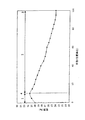
図1及び図3はそれぞれ、脱水処理前及びガラス化の前のプロセス段階における多孔質スート管の壁全体の径方向密度プロファイルを示す。Y軸上に、スート管の特定の密度が、相対単位(石英ガラスの理論密度に基づいた%)でグラフ化されている。X軸は、スート体の壁全体の厚みに基づいて、相対単位で半径を示す。半径「0」は、スート体の内壁に相当し、半径「100」は、その外壁に相当する。測定された各スート管は、約50mmの内径と約320mmの外径を有する。 1 and 3 show the radial density profiles of the entire walls of the porous soot tube before the dehydration process and before the vitrification, respectively. On the Y axis, the specific density of the soot tube is graphed in relative units (% based on the theoretical density of quartz glass). The X axis indicates the radius in relative units based on the overall thickness of the soot body wall. The radius “0” corresponds to the inner wall of the soot body, and the radius “100” corresponds to the outer wall thereof. Each measured soot tube has an inner diameter of about 50 mm and an outer diameter of about 320 mm.
図2及び図4は、脱水処理後およびガラス化後のプロセス段階の石英ガラス管の径方向屈折率プロファイルを示す。アンドープの石英ガラスと比較した屈折率差「Δn」がY軸上に示される。X軸は、石英ガラス管全体での径方向の位置「P」をミリ単位で示す。位置「P=0」は、内孔の中心軸を示す。 2 and 4 show the radial refractive index profile of the quartz glass tube in the process stage after dehydration and after vitrification. The refractive index difference “Δn” compared to undoped quartz glass is shown on the Y-axis. The X axis indicates the radial position “P” in the entire quartz glass tube in millimeters. The position “P = 0” indicates the central axis of the inner hole.
実施例
図1の径方向密度プロファイルでは、スート密度は、最初に、内側領域1において内側から外側に増加し、その後、約33%の最大値4から始まって、移行領域2で内側から外側に徐々に減少し、外側のジャケット3の領域で24%の値に達する。したがって、移行領域2内では、スート密度は全体で9%減少する。移行領域2は、スート管の壁厚の約90%を構成する。移行領域は、内側領域1に隣接し、内壁5から約15mm離れた、スート密度の最大値4から始まって、外側に向かって外側ジャケット3までの径方向に約120mmの長さにわたって広がる。
EXAMPLE In the radial density profile of FIG. 1, the soot density first increases from the inside to the outside in the inner region 1 and then starts from a maximum value of about 33%, from the inside to the outside in the
堆積プロセス後、スート管は、脱水処理にかけられ、その後ガラス化されて、石英ガラス管を形成する。図2は、脱水処理及びガラス化の後で、石英ガラス管で計測された屈折率プロファイルを示す。内孔21に隣接する石英ガラス管の壁22は、純粋な石英ガラスと比較して、Δn=0.0004の屈折率の増加を示す。石英ガラス管の壁22全体の屈折率は、内孔21から外壁23に至るまでほぼ均一であるということは特筆すべきことである。
After the deposition process, the soot tube is subjected to a dehydration process and then vitrified to form a quartz glass tube. FIG. 2 shows the refractive index profile measured with a quartz glass tube after dehydration and vitrification. The
ここで、図1で示した密度プロファイルを有するスート管及び図2で示した屈折率プロファイルを有する石英ガラス管の製造について、例を示して説明する。 Here, the manufacture of the soot tube having the density profile shown in FIG. 1 and the quartz glass tube having the refractive index profile shown in FIG. 2 will be described by way of example.
SiO2のスート粒子はデポジション・バーナーのバーナー炎でSiCl4を火炎加水分解することによって形成され、前記粒子は、長軸を中心に回転するキャリア・ロッドの上に層を成して堆積され、スート体を形成する。図2で示すように、径方向の密度曲線をスート体の内側に形成するために、第1のスート層の堆積中に、比較的高い表面温度が生じ、約30%の比較的高密度のスート領域が形成される。その後、スート密度は、上記に記載した約15mm離れた距離で、約32%の最大値4に達するまで、徐々に増加する。 SiO 2 soot particles are formed by flame hydrolysis of SiCl 4 with a burner flame in a deposition burner, the particles being deposited in layers on a carrier rod that rotates about its long axis. Form a soot body. As shown in FIG. 2, to form a radial density curve inside the soot body, a relatively high surface temperature occurs during the deposition of the first soot layer, with a relatively high density of about 30%. A soot region is formed. Thereafter, the soot density gradually increases until reaching a maximum value of about 32% at a distance of about 15 mm as described above.
「移行領域」2が、本発明の意義において発生するのが、この段階である。後のスート層の堆積中に、形成途中のスート体の表面温度は下がり続けるので、スート密度が減少する。このため、増大するスート体の表面の円周速度が一定のままとなるように、キャリア・ロッドの回転速度が減速し続ける。スート体の円周は増加するのに、バーナーの火炎温度は一定であるので、表面温度が低下する。この結果、図1で示した径方向の密度勾配をもたらす。より急勾配又はより平坦な勾配を生み出すために、水素と酸素の燃焼ガスの供給量を変えて、デポジション・バーナーの火炎温度を変化させる。 It is at this stage that the “transition region” 2 occurs in the meaning of the present invention. During the subsequent deposition of the soot layer, the surface temperature of the soot body during formation continues to decrease, so that the soot density decreases. For this reason, the rotational speed of the carrier rod continues to decelerate so that the circumferential speed of the surface of the soot body that increases is kept constant. As the circumference of the soot body increases, the flame temperature of the burner is constant, so the surface temperature decreases. This results in the radial density gradient shown in FIG. In order to produce a steeper or flatter slope, the hydrogen and oxygen combustion gas feed rates are varied to change the flame temperature of the deposition burner.
堆積プロセスの完了とキャリア・ロッドの除去後、図1で示した密度プロファイルを有するスート管が得られる。石英ガラス管は、下記の例によって説明された方法を用いてスート管から製造される。 After completion of the deposition process and removal of the carrier rod, a soot tube having the density profile shown in FIG. 1 is obtained. Quartz glass tubes are manufactured from soot tubes using the method described by the examples below.
上記で詳細に説明した方法の工程によって得られたスート体は、製造プロセスにより入った水酸基を除去するため、脱水処理にかけられる。このため、スート管は、垂直方向に脱水炉に入れられ、最初に、塩素含有雰囲気中で約900℃の温度で処理される。この処理は、約8時間続く。こうして、100wt.ppb.より低い水酸基濃度になる。 The soot body obtained by the steps of the method described in detail above is subjected to a dehydration treatment in order to remove the hydroxyl group introduced by the production process. For this purpose, the soot tube is placed in a dehydration furnace in the vertical direction and is first treated at a temperature of about 900 ° C. in a chlorine-containing atmosphere. This process lasts about 8 hours. Thus, 100 wt. ppb. Lower hydroxyl concentration.
脱水処理中に多孔質スート材料に作用する塩素の影響は、内側領域1の高密度と移行領域2の密度曲線によって補償されるので、本発明のスート管を用いて、図2で示した所定の均一な屈折率プロファイルを持つ石英ガラス管を得ることができる。
Since the influence of chlorine acting on the porous soot material during the dehydration process is compensated by the high density of the inner region 1 and the density curve of the
図2で示した屈折率プロファイルを持つ石英ガラスを製造するため、スート管は、縦型ガラス溶融炉において約1300℃の範囲の温度で焼結される。この際、スート体は、環状加熱ゾーンに供給され、炉の中でゾーン方向に加熱される。このプロセスにおいて、溶融面は、外側から内側に進行する。その後、焼結された(ガラス化された)管は、外径46mm、内径17mmに延伸される To produce quartz glass having the refractive index profile shown in FIG. 2, the soot tube is sintered at a temperature in the range of about 1300 ° C. in a vertical glass melting furnace. At this time, the soot body is supplied to the annular heating zone and heated in the zone direction in the furnace. In this process, the melt surface proceeds from outside to inside. The sintered (vitrified) tube is then stretched to an outer diameter of 46 mm and an inner diameter of 17 mm.
均一な屈折率分布は別として、このようにして得られた石英ガラス管は、水酸基の濃度が低く、そのため、光ファイバのためのプリフォームのコアに近い領域で使用できる。 Apart from the uniform refractive index profile, the quartz glass tube thus obtained has a low hydroxyl group concentration and can therefore be used in a region close to the preform core for an optical fiber.
比較するため、図3及び図4は、従来のスート管の径方向密度プロファイルと、従来のスート管から製造される石英ガラス管の屈折率プロファイルを示す。 For comparison, FIGS. 3 and 4 show the radial density profile of a conventional soot tube and the refractive index profile of a quartz glass tube made from the conventional soot tube.
比較例
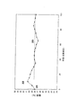
図3は、従来技術によって製造されたスート管の径方向密度プロファイルを示す。約40.5%のスート密度を有する内壁3から約15mm離れた最大値32は別として、密度は、スート管の壁厚全体でほぼ一定であり、平均約28%である(破線33)。
Comparative Example FIG. 3 shows the radial density profile of a soot tube manufactured according to the prior art. Apart from the
堆積プロセスの後、上記の例に基づいて説明されたように、スート管は同様の脱水処理にかけられ、その後、ガラス化されて延伸され、その結果、外径64mmで内径22mmの石英ガラス管となる。 After the deposition process, as explained on the basis of the above example, the soot tube is subjected to a similar dehydration treatment and then vitrified and stretched, resulting in a quartz glass tube having an outer diameter of 64 mm and an inner diameter of 22 mm. Become.
屈折率プロファイルを、この石英ガラス管で計測した。その結果は、図4に示す。内孔41に隣接する石英ガラス管の壁42の内側では、内側から外側に向かって屈折率は著しく減少する。内壁41の領域で約+0.0005の最大値から始まって、屈折率は、30%より多く減少し、外壁42の領域で+0.00035より少なくなるほどにまで減少する。したがって、径方向に不均一な屈折率分布を有する石英ガラス管が、従来のスート体をガラス化して延伸することによって得られた。
The refractive index profile was measured with this quartz glass tube. The result is shown in FIG. On the inner side of the
本発明の石英ガラス管は、MCVC法によってコア材料層を内側に堆積するため、好ましくは、サブストレート管として使用される。 The quartz glass tube of the present invention is preferably used as a substrate tube because the core material layer is deposited on the inside by the MCVC method.
Claims (7)
Applications Claiming Priority (2)
| Application Number | Priority Date | Filing Date | Title |
|---|---|---|---|
| DE10152328A DE10152328B4 (en) | 2001-10-26 | 2001-10-26 | Process for producing a tube made of quartz glass, tubular semi-finished product made of porous quartz glass and. Use of the same |
| PCT/EP2002/011278 WO2003037808A1 (en) | 2001-10-26 | 2002-10-09 | Method for producing a tube consisting of quartz glass, tubular semi-finished product consisting of porous quartz glass, and the use of the same |
Publications (3)
| Publication Number | Publication Date |
|---|---|
| JP2005507358A JP2005507358A (en) | 2005-03-17 |
| JP2005507358A5 JP2005507358A5 (en) | 2008-06-19 |
| JP4229442B2 true JP4229442B2 (en) | 2009-02-25 |
Family
ID=7703476
Family Applications (1)
| Application Number | Title | Priority Date | Filing Date |
|---|---|---|---|
| JP2003540095A Expired - Lifetime JP4229442B2 (en) | 2001-10-26 | 2002-10-09 | Method for producing a tube made of quartz glass, tubular intermediate product made of porous quartz glass, and use thereof |
Country Status (5)
| Country | Link |
|---|---|
| US (1) | US20050000250A1 (en) |
| JP (1) | JP4229442B2 (en) |
| CN (1) | CN1275887C (en) |
| DE (1) | DE10152328B4 (en) |
| WO (1) | WO2003037808A1 (en) |
Families Citing this family (19)
| Publication number | Priority date | Publication date | Assignee | Title |
|---|---|---|---|---|
| DE102006024831B4 (en) * | 2006-05-24 | 2008-03-27 | Heraeus Quarzglas Gmbh & Co. Kg | Process for producing a semifinished product from synthetic quartz glass |
| DE102010005954B4 (en) * | 2010-01-27 | 2020-11-19 | Heraeus Quarzglas Gmbh & Co. Kg | Porous carbon product |
| JP5695025B2 (en) * | 2010-03-03 | 2015-04-01 | 株式会社フジクラ | Optical fiber preform manufacturing method |
| DE102012013134B4 (en) * | 2012-07-03 | 2014-04-03 | Heraeus Quarzglas Gmbh & Co. Kg | Process for the production of cylinders made of quartz glass |
| WO2014099645A1 (en) * | 2012-12-20 | 2014-06-26 | Corning Incorporated | Methods for forming optical fiber preforms with selective diffusion layers |
| DE102013107435B4 (en) | 2013-07-12 | 2015-01-29 | Heraeus Quarzglas Gmbh & Co. Kg | Method for producing a quartz glass large tube |
| JP6097892B2 (en) * | 2015-03-31 | 2017-03-15 | 古河電気工業株式会社 | Method for producing porous glass preform for optical fiber |
| EP3088370B1 (en) * | 2015-04-28 | 2018-09-26 | Heraeus Quarzglas GmbH & Co. KG | Method and device for producing a glass tube |
| EP3390290B1 (en) | 2015-12-18 | 2023-03-15 | Heraeus Quarzglas GmbH & Co. KG | Production of an opaque quartz glass body |
| WO2017103125A1 (en) | 2015-12-18 | 2017-06-22 | Heraeus Quarzglas Gmbh & Co. Kg | Spray granulation of silica during the production of silica glass |
| US11339076B2 (en) | 2015-12-18 | 2022-05-24 | Heraeus Quarzglas Gmbh & Co. Kg | Preparation of carbon-doped silicon dioxide granulate as an intermediate in the preparation of quartz glass |
| KR20180095622A (en) | 2015-12-18 | 2018-08-27 | 헤래우스 크바르츠글라스 게엠베하 & 컴파니 케이지 | Manufacture of Silica Glass Products from Molten Crucibles Made of Refractory Metals |
| CN108698890A (en) | 2015-12-18 | 2018-10-23 | 贺利氏石英玻璃有限两合公司 | Quartz glass body is prepared using the dew point monitoring in melting baking oven |
| EP3390308A1 (en) | 2015-12-18 | 2018-10-24 | Heraeus Quarzglas GmbH & Co. KG | Glass fibers and preforms made of quartz glass having low oh, cl, and al content |
| WO2017103160A1 (en) | 2015-12-18 | 2017-06-22 | Heraeus Quarzglas Gmbh & Co. Kg | Production of silica glass articles from silica granluate |
| EP3390296A2 (en) | 2015-12-18 | 2018-10-24 | Heraeus Quarzglas GmbH & Co. KG | Production of a silica glass article in a multichamber furnace |
| US11952303B2 (en) | 2015-12-18 | 2024-04-09 | Heraeus Quarzglas Gmbh & Co. Kg | Increase in silicon content in the preparation of quartz glass |
| CN109153593A (en) | 2015-12-18 | 2019-01-04 | 贺利氏石英玻璃有限两合公司 | The preparation of synthetic quartz glass powder |
| WO2018093451A2 (en) * | 2016-09-21 | 2018-05-24 | Corning Incorporated | Optical fibers having a varying clad index and methods of forming same |
Family Cites Families (14)
| Publication number | Priority date | Publication date | Assignee | Title |
|---|---|---|---|---|
| JPS60161347A (en) * | 1984-01-24 | 1985-08-23 | Sumitomo Electric Ind Ltd | Preparation of parent material for optical fiber glass |
| JPS60186429A (en) * | 1984-03-01 | 1985-09-21 | Sumitomo Electric Ind Ltd | Manufacture of optical fiber preform |
| DE3422997A1 (en) * | 1984-06-22 | 1986-01-02 | Standard Elektrik Lorenz Ag, 7000 Stuttgart | METHOD FOR PRODUCING LIGHTWAVE GUIDES |
| JPS61201637A (en) * | 1985-03-01 | 1986-09-06 | Sumitomo Electric Ind Ltd | Production of base material for optical fiber |
| US4810276A (en) * | 1987-08-05 | 1989-03-07 | Corning Glass Works | Forming optical fiber having abrupt index change |
| JPH01160839A (en) * | 1987-12-18 | 1989-06-23 | Nippon Telegr & Teleph Corp <Ntt> | Production of preform for optical fiber |
| DE69027765T2 (en) * | 1989-10-31 | 1997-01-09 | Fujitsu Ltd | MANUFACTURING METHOD FOR A BASE MATERIAL FOR OPTICAL FIBERS |
| US5278931A (en) * | 1992-12-31 | 1994-01-11 | Corning Incorporated | Low bend loss singlemode optical waveguide fiber |
| US6376401B1 (en) * | 1998-09-07 | 2002-04-23 | Tosoh Corporation | Ultraviolet ray-transparent optical glass material and method of producing same |
| JP2000264647A (en) * | 1999-03-12 | 2000-09-26 | Shin Etsu Chem Co Ltd | Porous glass preform |
| JP2000272930A (en) * | 1999-03-26 | 2000-10-03 | Mitsubishi Cable Ind Ltd | Production of optical fiber preform |
| DE10050324C1 (en) * | 2000-10-10 | 2001-12-13 | Heraeus Quarzglas | Production of tube made from doped quartz glass used as preform for optical fibers comprises flame hydrolysis of first starting mixture containing silicon and second starting mixture forming germanium dioxide |
| EP1383714B1 (en) * | 2001-04-27 | 2011-04-13 | Prysmian S.p.A. | Method for producing an optical fiber preform |
| US8516855B2 (en) * | 2001-04-27 | 2013-08-27 | Prysmian Cavi E Sistemi Energia S.R.L. | Method for producing an optical fiber preform |
-
2001
- 2001-10-26 DE DE10152328A patent/DE10152328B4/en not_active Expired - Lifetime
-
2002
- 2002-10-09 WO PCT/EP2002/011278 patent/WO2003037808A1/en active Application Filing
- 2002-10-09 CN CNB028212274A patent/CN1275887C/en not_active Expired - Lifetime
- 2002-10-09 US US10/493,774 patent/US20050000250A1/en not_active Abandoned
- 2002-10-09 JP JP2003540095A patent/JP4229442B2/en not_active Expired - Lifetime
Also Published As
| Publication number | Publication date |
|---|---|
| CN1275887C (en) | 2006-09-20 |
| US20050000250A1 (en) | 2005-01-06 |
| CN1575261A (en) | 2005-02-02 |
| DE10152328B4 (en) | 2004-09-30 |
| JP2005507358A (en) | 2005-03-17 |
| WO2003037808A1 (en) | 2003-05-08 |
| DE10152328A1 (en) | 2003-05-22 |
Similar Documents
| Publication | Publication Date | Title |
|---|---|---|
| JP4229442B2 (en) | Method for producing a tube made of quartz glass, tubular intermediate product made of porous quartz glass, and use thereof | |
| US20020136515A1 (en) | Substrate tube and process for producing a preform for an optical fiber | |
| WO2002102730A1 (en) | Method of manufacturing multi-segmented optical fiber and preform | |
| US8516855B2 (en) | Method for producing an optical fiber preform | |
| EP2726422A1 (en) | Methods for producing optical fiber preforms with low index trenches | |
| US10807901B2 (en) | Method for producing an optical blank from synthetic quartz glass | |
| WO2015034991A2 (en) | Method of making updoped cladding by using silicon tertrachloride as the dopant | |
| EP3647282B1 (en) | Method for manufacturing a glass preform for optical fibres | |
| JPH0948629A (en) | Optical fiber and its production | |
| GB2307908A (en) | Making an optical fibre preform | |
| EP1699741A1 (en) | Method of making an optical fiber preform | |
| CN111615499B (en) | Method for manufacturing optical fiber preform, method for manufacturing optical fiber, and optical fiber | |
| EP1383714B1 (en) | Method for producing an optical fiber preform | |
| US7021083B2 (en) | Manufacture of high purity glass tubes | |
| WO2008003613A1 (en) | Method for producing a tubular semifinished product from fluorine-doped quartz glass | |
| EP1505039B1 (en) | Method of manufacturing an optical fiber preform | |
| WO2001072648A1 (en) | Substrate tube and process for producing a preform for an optical fiber | |
| EP3971145B1 (en) | Manufacturing method of glass base material for optical fiber | |
| JP2003505321A (en) | Method for producing a glass preform and optical fiber obtained from said preform | |
| JP3343079B2 (en) | Optical fiber core member, optical fiber preform, and method of manufacturing the same | |
| JP2000063147A (en) | Optical fiber preform and its production | |
| JP2022127161A (en) | Method for manufacturing optical fiber preform and method for manufacturing optical fiber | |
| EP0135175B1 (en) | Methods for producing optical fiber preform and optical fiber | |
| JP2003112939A (en) | Producing method for glass preform for optical fiber | |
| JP2004175614A (en) | Manufacturing method of glass preform |
Legal Events
| Date | Code | Title | Description |
|---|---|---|---|
| A621 | Written request for application examination |
Free format text: JAPANESE INTERMEDIATE CODE: A621 Effective date: 20050328 |
|
| A131 | Notification of reasons for refusal |
Free format text: JAPANESE INTERMEDIATE CODE: A131 Effective date: 20080212 |
|
| A524 | Written submission of copy of amendment under article 19 pct |
Free format text: JAPANESE INTERMEDIATE CODE: A524 Effective date: 20080424 |
|
| A131 | Notification of reasons for refusal |
Free format text: JAPANESE INTERMEDIATE CODE: A131 Effective date: 20080707 |
|
| A521 | Request for written amendment filed |
Free format text: JAPANESE INTERMEDIATE CODE: A523 Effective date: 20080829 |
|
| TRDD | Decision of grant or rejection written | ||
| A01 | Written decision to grant a patent or to grant a registration (utility model) |
Free format text: JAPANESE INTERMEDIATE CODE: A01 Effective date: 20081031 |
|
| A01 | Written decision to grant a patent or to grant a registration (utility model) |
Free format text: JAPANESE INTERMEDIATE CODE: A01 |
|
| A61 | First payment of annual fees (during grant procedure) |
Free format text: JAPANESE INTERMEDIATE CODE: A61 Effective date: 20081201 |
|
| R150 | Certificate of patent or registration of utility model |
Ref document number: 4229442 Country of ref document: JP Free format text: JAPANESE INTERMEDIATE CODE: R150 Free format text: JAPANESE INTERMEDIATE CODE: R150 |
|
| FPAY | Renewal fee payment (event date is renewal date of database) |
Free format text: PAYMENT UNTIL: 20111212 Year of fee payment: 3 |
|
| FPAY | Renewal fee payment (event date is renewal date of database) |
Free format text: PAYMENT UNTIL: 20121212 Year of fee payment: 4 |
|
| R250 | Receipt of annual fees |
Free format text: JAPANESE INTERMEDIATE CODE: R250 |
|
| FPAY | Renewal fee payment (event date is renewal date of database) |
Free format text: PAYMENT UNTIL: 20131212 Year of fee payment: 5 |
|
| R250 | Receipt of annual fees |
Free format text: JAPANESE INTERMEDIATE CODE: R250 |
|
| R250 | Receipt of annual fees |
Free format text: JAPANESE INTERMEDIATE CODE: R250 |
|
| R250 | Receipt of annual fees |
Free format text: JAPANESE INTERMEDIATE CODE: R250 |
|
| R250 | Receipt of annual fees |
Free format text: JAPANESE INTERMEDIATE CODE: R250 |
|
| R250 | Receipt of annual fees |
Free format text: JAPANESE INTERMEDIATE CODE: R250 |
|
| R250 | Receipt of annual fees |
Free format text: JAPANESE INTERMEDIATE CODE: R250 |
|
| R250 | Receipt of annual fees |
Free format text: JAPANESE INTERMEDIATE CODE: R250 |
|
| R250 | Receipt of annual fees |
Free format text: JAPANESE INTERMEDIATE CODE: R250 |
|
| R250 | Receipt of annual fees |
Free format text: JAPANESE INTERMEDIATE CODE: R250 |
|
| R250 | Receipt of annual fees |
Free format text: JAPANESE INTERMEDIATE CODE: R250 |
|
| EXPY | Cancellation because of completion of term |