JP4228551B2 - Engine system diagnostic device - Google Patents
Engine system diagnostic device Download PDFInfo
- Publication number
- JP4228551B2 JP4228551B2 JP2001106165A JP2001106165A JP4228551B2 JP 4228551 B2 JP4228551 B2 JP 4228551B2 JP 2001106165 A JP2001106165 A JP 2001106165A JP 2001106165 A JP2001106165 A JP 2001106165A JP 4228551 B2 JP4228551 B2 JP 4228551B2
- Authority
- JP
- Japan
- Prior art keywords
- engine
- warm
- mode
- water temperature
- stored
- Prior art date
- Legal status (The legal status is an assumption and is not a legal conclusion. Google has not performed a legal analysis and makes no representation as to the accuracy of the status listed.)
- Expired - Lifetime
Links
Images


Classifications
-
- F—MECHANICAL ENGINEERING; LIGHTING; HEATING; WEAPONS; BLASTING
- F02—COMBUSTION ENGINES; HOT-GAS OR COMBUSTION-PRODUCT ENGINE PLANTS
- F02N—STARTING OF COMBUSTION ENGINES; STARTING AIDS FOR SUCH ENGINES, NOT OTHERWISE PROVIDED FOR
- F02N19/00—Starting aids for combustion engines, not otherwise provided for
- F02N19/02—Aiding engine start by thermal means, e.g. using lighted wicks
- F02N19/04—Aiding engine start by thermal means, e.g. using lighted wicks by heating of fluids used in engines
- F02N19/10—Aiding engine start by thermal means, e.g. using lighted wicks by heating of fluids used in engines by heating of engine coolants
-
- F—MECHANICAL ENGINEERING; LIGHTING; HEATING; WEAPONS; BLASTING
- F01—MACHINES OR ENGINES IN GENERAL; ENGINE PLANTS IN GENERAL; STEAM ENGINES
- F01P—COOLING OF MACHINES OR ENGINES IN GENERAL; COOLING OF INTERNAL-COMBUSTION ENGINES
- F01P11/00—Component parts, details, or accessories not provided for in, or of interest apart from, groups F01P1/00 - F01P9/00
- F01P11/14—Indicating devices; Other safety devices
- F01P11/20—Indicating devices; Other safety devices concerning atmospheric freezing conditions, e.g. automatically draining or heating during frosty weather
-
- F—MECHANICAL ENGINEERING; LIGHTING; HEATING; WEAPONS; BLASTING
- F02—COMBUSTION ENGINES; HOT-GAS OR COMBUSTION-PRODUCT ENGINE PLANTS
- F02D—CONTROLLING COMBUSTION ENGINES
- F02D41/00—Electrical control of supply of combustible mixture or its constituents
- F02D41/22—Safety or indicating devices for abnormal conditions
-
- F—MECHANICAL ENGINEERING; LIGHTING; HEATING; WEAPONS; BLASTING
- F02—COMBUSTION ENGINES; HOT-GAS OR COMBUSTION-PRODUCT ENGINE PLANTS
- F02M—SUPPLYING COMBUSTION ENGINES IN GENERAL WITH COMBUSTIBLE MIXTURES OR CONSTITUENTS THEREOF
- F02M25/00—Engine-pertinent apparatus for adding non-fuel substances or small quantities of secondary fuel to combustion-air, main fuel or fuel-air mixture
- F02M25/08—Engine-pertinent apparatus for adding non-fuel substances or small quantities of secondary fuel to combustion-air, main fuel or fuel-air mixture adding fuel vapours drawn from engine fuel reservoir
- F02M25/0809—Judging failure of purge control system
-
- F—MECHANICAL ENGINEERING; LIGHTING; HEATING; WEAPONS; BLASTING
- F01—MACHINES OR ENGINES IN GENERAL; ENGINE PLANTS IN GENERAL; STEAM ENGINES
- F01P—COOLING OF MACHINES OR ENGINES IN GENERAL; COOLING OF INTERNAL-COMBUSTION ENGINES
- F01P11/00—Component parts, details, or accessories not provided for in, or of interest apart from, groups F01P1/00 - F01P9/00
- F01P11/14—Indicating devices; Other safety devices
- F01P2011/205—Indicating devices; Other safety devices using heat-accumulators
-
- F—MECHANICAL ENGINEERING; LIGHTING; HEATING; WEAPONS; BLASTING
- F01—MACHINES OR ENGINES IN GENERAL; ENGINE PLANTS IN GENERAL; STEAM ENGINES
- F01P—COOLING OF MACHINES OR ENGINES IN GENERAL; COOLING OF INTERNAL-COMBUSTION ENGINES
- F01P2023/00—Signal processing; Details thereof
-
- Y—GENERAL TAGGING OF NEW TECHNOLOGICAL DEVELOPMENTS; GENERAL TAGGING OF CROSS-SECTIONAL TECHNOLOGIES SPANNING OVER SEVERAL SECTIONS OF THE IPC; TECHNICAL SUBJECTS COVERED BY FORMER USPC CROSS-REFERENCE ART COLLECTIONS [XRACs] AND DIGESTS
- Y02—TECHNOLOGIES OR APPLICATIONS FOR MITIGATION OR ADAPTATION AGAINST CLIMATE CHANGE
- Y02T—CLIMATE CHANGE MITIGATION TECHNOLOGIES RELATED TO TRANSPORTATION
- Y02T10/00—Road transport of goods or passengers
- Y02T10/10—Internal combustion engine [ICE] based vehicles
- Y02T10/40—Engine management systems
Landscapes
- Engineering & Computer Science (AREA)
- Chemical & Material Sciences (AREA)
- Combustion & Propulsion (AREA)
- Mechanical Engineering (AREA)
- General Engineering & Computer Science (AREA)
- Life Sciences & Earth Sciences (AREA)
- Atmospheric Sciences (AREA)
- Combined Controls Of Internal Combustion Engines (AREA)
- Control Of Vehicle Engines Or Engines For Specific Uses (AREA)
- Supplying Secondary Fuel Or The Like To Fuel, Air Or Fuel-Air Mixtures (AREA)
- Exhaust Gas After Treatment (AREA)
Description
【0001】
【発明の属する技術分野】
本発明はエンジンシステムの診断装置に係り、詳しくは少なくとも冷間始動時にエンジンを暖機する熱媒体を備蓄する蓄熱装置を備えたエンジンシステムにおいて、同システムの各箇所の暖機態様を診断する診断装置に関する。
【0002】
【従来の技術】
従来より、エンジンシステムの1つとして、燃料タンクで発生する燃料蒸気(エバポ)をキャニスタに捕集し、その捕集された燃料蒸気を適宜キャニスタから吸気通路へパージするようにしたエバポパージシステムがある。
【0003】
こうしたエバポパージシステムは、通常、燃料タンク内にて発生した燃料蒸気を捕集するキャニスタと、燃料タンクとキャニスタとを連通するベーパ通路と、キャニスタと吸気通路とを連通するパージ通路とを備えるシステムとして構成される。また、同システムにおいて、パージ通路の通路途中には開閉制御の可能なパージ制御弁が、キャニスタには大気導入の可能な大気導入弁が備えられている。
【0004】
一方、上記のようなエバポパージシステムについて、そのエバポ経路の穴開きや裂傷等に起因する漏れの有無を診断するエバポパージシステムの異常診断装置がある。かかる異常診断は、基本的には、キャニスタへの大気導入を一時的に遮断すると共に、パージ経路とエンジンの吸気通路との連通を断つことでパージ経路を孤立空間化し、その後のパージ経路内の圧力変化に基づいて異常の有無を診断するものである。
【0005】
すなわち、エバポパージシステムに漏れがある場合には、パージ経路内は大気と導通状態となるため、エバポ経路内圧は大気圧に収束する。これに対し、エバポパージシステムに漏れがない場合には、エバポ経路内の気化燃料がその飽和蒸気圧へと収束するため、同エバポ経路内圧は、同収束値とエバポ経路内の気化燃料以外の気体の分圧値との和に収束する。このように、これら2つの要因によるエバポ経路内圧の変化の差に基づいてエバポパージシステムの異常の有無を診断することができる。
【0006】
ただし、実際のエバポ経路内の圧力変化態様は、エバポ経路の漏れの有無のみに依存するものではなく、様々なパラメータに依存している。例えば、エバポ経路に穴がない場合において、エバポ経路内の温度が高い場合には、飽和蒸気圧も高くなるため、同経路内の温度が低い場合と比べてエバポ経路内圧は高くなる傾向にある。このように、エバポ経路内の圧力が様々なパラメータによって影響されるために、同経路の漏れの有無によって必ずしも明確な差を生じるわけではなく、結果としてエバポパージシステムの異常診断を正確に行うことができないことがある。
【0007】
そこで従来、例えば特開平6−81728号公報に見られるように、こうしたエバポパージシステムの異常診断をエンジンの冷間始動時に限定して行う提案もなされている。すなわち、エンジンの冷間始動時には、エバポ経路内において気化燃料のしめる分圧が小さいために、同気化燃料のエバポ経路内圧への影響を好適に抑制することができ、これにより的確に異常診断を行うことができる。
【0008】
【発明が解決しようとする課題】
一方、冷間始動時におけるエンジンの暖機促進等を目的として、エンジンの冷却水系に蓄熱装置を備える提案もなされてきた。この蓄熱装置は、例えばエンジンへ冷却水を循環させる通路と、同通路を循環する冷却水を保温備蓄する蓄熱器と、エンジン及び蓄熱器間で冷却水を循環させる電動ポンプを備えている。こうした蓄熱装置を備え、高温の冷却水を蓄熱器に備蓄しておくことで、冷間始動時において同蓄熱器に備蓄された冷却水(熱媒体)によってエンジンの暖機を促進することができる。
【0009】
ただし、上記蓄熱装置を備えたエンジンに上記エバポパージシステムの異常診断装置を適用する場合には、同異常診断装置による異常診断を的確に行うことができない。すなわち、上記蓄熱装置によってエンジンは暖機されているために、上記装置ではエバポパージシステムの異常診断を行うための条件が満たされなくなる。ところが、蓄熱装置によるエンジンの暖機では、燃料タンク内まで十分に暖機されるとは限らないため、蓄熱装置によってエンジンが暖機されるとはいえ、実際にはエバポパージシステムの異常診断を的確に行うことが可能であることもある。結局、蓄熱装置によって始動前に予めエンジンを暖機する制御を行った場合には、エバポパージシステムの異常診断を行う条件が整っているにもかかわらず、異常診断条件が成立していないと判断することで異常診断を的確に行えないおそれがある。
【0010】
なお、上記エバポパージシステムの異常診断に限らず、始動に先立ちエンジンを暖機する蓄熱装置を備えるエンジンシステムでの暖機診断に際しては、その診断条件の誤認が懸念されるこうした実情も概ね共通したものとなっている。
【0011】
本発明は上記実情に鑑みてなされたものであり、その目的は、蓄熱装置を備えたエンジンシステムにあって、より的確な暖機診断を行うことのできるエンジンシステムの診断装置を提供することにある。
【0012】
【課題を解決するための手段】
以下、上記目的を達成するための手段及びその作用効果について記載する。
請求項1に記載の発明は、エンジンの始動に先立ち、これを暖機すべく蓄熱装置を備えたエンジンにおけるエバポパージシステム及び前記エンジンの排気系に備えられた触媒の少なくとも一方の暖機態様の診断を行う装置であって、前記蓄熱装置による前記エンジンの暖機に先立ち、同エンジンの暖機態様の検出及び該検出結果の記憶保持を行う暖機状態検出手段と、前記蓄熱装置による前記エンジンの暖機後に、前記暖機状態検出手段によって記憶保持された前記エンジンの暖機態様に基づいて前記エンジンの暖機後における前記エバポパージシステム及び前記触媒の少なくとも一方の暖機態様の診断を行う診断手段とを備えることをその要旨とする。
【0013】
上記構成では、エンジンの暖機に先立ち、エンジンの暖機態様を検出するとともにこの検出結果を記憶保持し、これに基づいてエバポパージシステム及び前記触媒の少なくとも一方の暖機態様の診断を行う。このため、蓄熱装置によるエンジンの暖機前のエンジンの暖機態様を、同蓄熱装置によるエンジン暖機後にも把握することができ、ひいては、エバポパージシステム及び前記触媒の少なくとも一方の暖機診断をより的確に行うことができるようになる。
請求項2に記載の発明は、請求項1記載のエンジンシステムの診断装置において、前記診断手段は、前記蓄熱装置による前記エンジンの暖機後に、前記エンジンの吸気温及び前記暖機状態検出手段によって記憶保持された前記エンジンの暖機態様に基づいて前記エバポパージシステム及び前記触媒の少なくとも一方の暖機態様の診断を行うことをその要旨とする。
請求項3に記載の発明は、請求項1又は2記載のエンジンシステムの診断装置において、前記診断手段は前記エンジンの始動後に同エンジンの暖機態様の診断を行うことをその要旨とする。
【0014】
なお、上記請求項1〜3のいずれかに記載の発明は、請求項4記載の発明によるように、前記暖機態様検出手段は、前記検出結果を不揮発性のメモリに記憶保持するものである構成としてもよい。
【0015】
このように、不揮発性のメモリに記憶保持するようにすれば、蓄熱装置によるエンジン暖機前のエンジンの暖機態様の検出結果を好適に記憶保持することができる。
【0016】
請求項5記載の発明は、請求項4記載の発明において、前記エンジンの始動のための予備操作を検知する検知手段を更に備え、前記暖機状態検出手段は、前記検知手段により前記予備操作が検知されたときに前記暖機態様の検出及び該検出結果の記憶保持を行うことをその要旨とする。
【0017】
上記構成によれば、エンジンの始動のための予備操作が検知されたときに、暖機態様の検出及び該検出結果の記憶保持を行うことで、これらの処理を迅速に行うことができるようになる。
【0018】
請求項6記載の発明は、請求項4記載の発明において、前記エンジンの始動のための予備操作を検知する検知手段を更に備え、前記暖機態様検出手段は、エンジン稼働中にイグニッションスイッチが切られたことに基づいて前記不揮発性メモリに記憶保持される値を初期化する初期化手段と、前記検知手段により前記予備操作が検知されたこと、及び前記不揮発性メモリに記憶保持されている値が初期値であることを条件に、前記初期値の前記検出結果による書き換えを行う書換手段とを備えることをその要旨とする。
【0019】
エンジン始動のための予備操作が検知されることでエンジンの暖機態様を検出し、これを不揮発性メモリに記憶保持するようにした場合、エンジン始動のための予備操作が短期間に何度も繰り返されると、同記憶保持される検出結果がその都度更新されることがある。この場合、蓄熱装置によるエンジン暖機後のエンジンの暖機態様の検出結果が不揮発性メモリに記憶保持されるおそれがある。
【0020】
この点、上記構成では、エンジン稼働中にイグニッションスイッチが切られた履歴に基づいてエンジンの暖機態様の検出結果が不揮発性メモリに記憶保持される。このため、エンジン始動のための予備操作が短期間に繰り返されたとしても、この予備操作に連動して不揮発性メモリの記憶値が更新されることを回避することができる。
【0021】
請求項7記載の発明は、請求項5又は6記載の発明において、前記検知手段による前記予備操作の検知後にエンジンが所定以上暖機されていないときに前記蓄熱装置による暖機を許容するとともに、同暖機が完了するまで前記エンジンの始動を禁止する手段を更に備えることをその要旨とする。
【0022】
上記構成によれば、蓄熱装置によるエンジンの暖機を迅速に行うことができるようになる。また、上記構成によれば、エンジンの暖機が完了するまでエンジンの始動を禁止することで、同始動を好適に行うことができるようになる。
【0023】
なお、上記請求項5〜7のいずれかに記載の発明は、請求項8記載の発明によるように、前記検知手段は、前記エンジンの始動のための予備操作として、前記エンジンの搭載される車両のドアの開操作及びイグニッションスイッチのオン操作の少なくとも一方を検知するものであるようにしてもよい。
【0025】
【発明の実施の形態】
以下、本発明にかかるエンジンシステムの診断装置を、エバポパージシステムの異常診断装置に適用した一実施形態について、図面を参照しつつ説明する。
【0026】
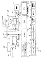
図1に、本実施形態にかかるエバポパージシステムの異常診断装置の全体構成を示す。
同図1に示すエンジン10は、冷却水を熱媒体として冷却及び加熱される水冷式のエンジンである。この冷却水の循環を行うべく、本実施形態のエンジンシステムは、エンジン10の図示しないクランク軸の出力トルクによって駆動するウォータポンプ21を備えている。そして、同ウォータポンプ21による冷却水の循環通路として、同システムは、バイパス通路22と、冷却通路23とを備えている。ここで、冷却通路23の途中には、冷却水を冷却すべくラジエータ24が備えられている。
【0027】
これらバイパス通路22及び冷却通路23の交差する部分には、これら2つの循環通路のいずれかとエンジン10との間で冷却水を循環させるべく、サーモスタット25が備えられている。このサーモスタット25は、冷却水の温度に応じてバイパス通路22内の冷却水及び冷却通路23の冷却水のいずれかとエンジン10とを選択的に連通させるものである。すなわち、エンジン10内を循環する冷却水の温度(以下、エンジン水温)が所定温度以下であるときには、エンジン10の暖機を妨げないように、バイパス通路22側が選択される。これに対し、エンジン水温が所定温度を上回ると、冷却水をラジエータ24によって冷却すべく冷却通路23が選択される。
【0028】
更に、上記システムでは、エンジン10の始動前にこれを暖機すべく蓄熱装置として、以下のものを備えている。すなわち、始動前にエンジン10を暖機すべく高温の冷却水を備蓄する蓄熱器31、同蓄熱器31及びエンジン10間の冷却水の循環通路としての暖機通路32、同蓄熱器31及びエンジン10間に冷却水を循環させる電動ポンプ33を備えている。
【0029】
ここで、蓄熱器31は、冷却水の熱を蓄熱しつつ同冷却水を貯蔵する容器である。この蓄熱器31の出口側にはワンウェイバルブ31aが、またその入口側にはワンウェイバルブ31bがそれぞれ設けられている。そして、電動ポンプ33の働きによってワンウェイバルブ31bを介して冷却水が蓄熱器31に流入すると、それと連動してワンウェイバルブ31aを介して同蓄熱器31内に貯蔵されていた高温の冷却水が排出される。
【0030】
次に、上記システムにおけるエバポパージシステムについて説明する。
同エバポパージシステムは、以下のものを備えている。まず、燃料タンク40と、同燃料タンク40内にて発生した燃料蒸気を捕集するキャニスタ41とを備えている。また、燃料タンク40及びキャニスタ41間を連通するベーパ通路42と、キャニスタ41及びエンジン10の吸気通路11とを連通するパージ通路43とを備えている。
【0031】
ここで、キャニスタ41は、その内部に、燃料蒸気を吸着させて一時的に蓄える吸着材(活性炭)41aを備えている。そして、この吸着材41aに吸着した燃料蒸気は、同キャニスタ41の内部空間が減圧されることによって再離脱される構成となっている。
【0032】
こうしたキャニスタ41内への燃料蒸気の吸着や再離脱を的確に行うべく、上記エバポパージシステムは、次のものを備えている。まず、キャニスタ41には、同キャニスタ41内の圧力が大気圧よりも高い所定圧以上の状態に達すると開弁し、キャニスタ41内の余分な空気を排出するための大気弁41bを備えている。また、キャニスタ41及びエンジン10の吸気通路11間を連通及び遮断すべく、パージ通路43には例えば電磁弁からなるパージ制御弁44が備えられている。更に、キャニスタ41には、キャニスタ41内に大気を導入すべく、例えば電磁弁からなる大気導入弁41cが備えられている。
【0033】
そして、キャニスタ41内の吸着材41aに吸着された燃料蒸気は、大気導入弁41c及びパージ制御弁44が開弁制御されることで、キャニスタ41内が減圧されると再離脱される。これにより、燃料蒸気は、エンジン10の吸気通路11にパージされる。
【0034】
更に、上記エンジンシステムは、エンジン10や、蓄熱装置、エバポパージシステムを制御すべく、電子制御装置(以下、ECU)50と、エンジン始動のための予備操作を検知する部分、ECU50への給電を行う給電装置、更にはエンジンシステムの各種特性を検出してECU50に供給する各種センサとを備えている。
【0035】
ここで、ECU50は次のものを備えている。まず、上記各種センサの検出結果等を参照しつつ各種演算を行う中央演算処理装置(CPU)51と、CPU51において行われる演算のプログラム等が格納されるROM52とを備えている。また、同ECU50への電力の供給の有無にかかわらず常時給電状態にある不揮発性のメモリとしてのバックアップRAM51を備えている。更に、ECU50に電力が供給されているときのみ給電状態となるノーマルRAM(以下、N−RAM)53を備えている。
【0036】
ここで、バックアップRAM54には常時給電がなされているために、同バックアップRAM54に記憶されるデータは、ECU50の給電態様にかかわらず、保持される。これに対し、N−RAM53は、ECU50が給電状態にあるときのみ給電状態となるために、このN−RAM53に記憶されたデータは、ECU50への電力の供給が断たれると消去される。
【0037】
このECU50への給電は、上記エンジン10始動のための予備操作を検知することで開始される。そして、本実施形態では、このエンジン10始動のための予備操作の検知を、上記エンジンシステムの搭載される車両の例えば運転席近傍に設けられるイグニッション操作部の操作や、運転席側のドアの開動作を検知することで行う。
【0038】
具体的には、本実施形態では、上記検知部や給電装置として、バッテリ61やイグニッションスイッチ部(IGスイッチ)62、ドアスイッチ部63を備えている。
【0039】
ここで、IGスイッチ部62は、イグニッション操作部や、イグニッションスイッチ、リレーなどを備えている。ここで、イグニッション操作部は、イグニッションスイッチをオン/オフ制御するためのものである。そして、イグニッションスイッチがオンとされることで、ECU50への給電が行われる。また、同イグニッションスイッチがオフとされると、これに基づいてECU50への給電が中止される。ただし、この際、ECU50内で後処理を可能とすべく、リレーが用いられるなどしてイグニッションスイッチのオフ制御後の所定期間に渡ってECU50への給電が維持される。なお、このイグニッション操作部の操作により、イグニッションスイッチのオン/オフ制御のみならず、図示しないスタータの起動制御も行われる。
【0040】
一方、ドアスイッチ部63は、上記車両の運転席のドアが開かれたときに、これを検知してECU50を給電状態とするものである。
上記IGスイッチ部62やドアスイッチ部63によってエンジン10の始動のための予備操作が検知されると、本実施形態では、エンジン10の暖機態様を把握するようにする。そして、同エンジン10の暖機が十分でないときには、エンジン10の始動に先立ち、蓄熱装置によりエンジン10を暖機させる。
【0041】
具体的には、エンジン10の暖機態様をエンジン10を循環する冷却水の温度(以下、エンジン水温)によって把握する。そして、エンジン水温が所定温度以下であると判断されると、上記蓄熱器31に備蓄された高温の冷却水によってエンジン10を所定時間暖機させる(プレヒート)。本実施形態においては、このプレヒートが終了するまではエンジン10の始動を禁止する。
【0042】
ただし、例えば荷物を取り出す等の目的で運転席側のドアが開操作される等、上記態様にてエンジン10の始動のための予備操作を検知したとしても、必ずしもエンジン10が始動されるとは限らない。そこで、本実施形態においては、プレヒート終了後、所定期間経過してもイグニッション操作部の操作がなされない場合には、ECU50への給電を中止する制御をする。
【0043】
このECU50への給電の中止に際しては、プレヒート制御によって蓄熱器31からエンジン10へ供給された高温の冷却水を回収することが望ましい場合がある。したがって、本実施形態では、エンジン水温が蓄熱器31内の水温(以下、蓄熱器内水温)よりも高いと判断されるときには、上記ECU50への給電の中止に先立ち、エンジン10の冷却水を蓄熱器31に回収する。
【0044】
こうした一連の制御を行うべく、本実施形態では、エンジン10内を循環する冷却水の温度又はその相当値を検出する水温センサ71と、蓄熱器内の水温又はその相当値を検出する蓄熱器内水温センサ72とを備えている。
【0045】
ここで、エンジン10の始動のための予備操作が検知されることで、ECU50への給電が開始された場合に行われるプレヒート処理の手順について、図2に基づいて更に説明する。
【0046】
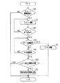
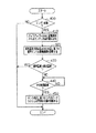
図2は、上記プレヒートの処理手順を示すフローチャートである。この処理は、例えば所定周期毎に繰り返し実行される。
この一連の処理においては、まず、ステップ100において、プレヒート開始条件が成立しているかが判断される。この開始条件は、例えばエンジン水温が所定温度以下であることや、ECU50の起動後所定時間内であること、エンジン10の停止状態であること等である。
【0047】
そして、プレヒート条件が成立していると判断されると、エンジン10の暖機が十分に行われたと判断されるまで同制御を実行する(ステップ110,120)。ここで、エンジンが十分暖機されたと判断されるプレヒート終了条件としては、例えばエンジン水温が所定温度以上となること及びプレヒート処理開始から所定時間経過したときの論理和を用いる等すればよい。
【0048】
こうしてプレヒート処理が終了した場合に、エンジン10の始動が許可される。すなわち、イグニッション操作部の操作によってスタータの起動指令がなされているときには、エンジン10を始動する(ステップ130,140)。これに対し、スタータ起動指令がなされていないときには、プレヒート処理終了後所定時間を待ってエンジン水温と蓄熱器内水温との比較に基づいてエンジン10に供給された冷却水を回収するか否かを判断する(ステップ130、150、160)。そして、回収すると判断されたときには、エンジン10に供給された冷却水を蓄熱器31に回収する(ステップ170)。
【0049】
一方、ステップ100においてプレヒート開始条件が成立しない場合や、ステップ140においてエンジンの始動がなされた場合、ステップ160においてエンジン水温が蓄熱器内水温以下だった場合、ステップ170において冷却水を回収した場合には、このルーチンを処理を一旦終了する。
【0050】
なお、本実施形態においては、イグニッションスイッチのオフ操作等によるECU50への給電の中止に際しても、エンジン水温が蓄熱器内水温よりも高い場合には、同中止に先立ちエンジン10の冷却水を蓄熱器31に回収する。
【0051】
次に、本実施形態におけるエバポパージシステムの異常診断について説明する。
同エバポパージシステムの異常診断は、基本的には、先の図1に示したパージ制御弁44及び大気導入弁41cを閉制御することで、燃料タンク40、ベーパ通路42、キャニスタ41、パージ通路43によって形成される空間(エバポ経路)を孤立空間化し、同空間の圧力の変化態様に基づいて行う。この際、燃料タンク40内の燃料の温度が十分に低いときには、燃料蒸気がエバポ経路内の圧力変化に与える影響を抑制することができる。
【0052】
そして、この場合、エバポ経路に漏れのない場合には、燃料タンク40の燃料が消費されることで同経路内圧は一旦低下する。これに対し、エバポ経路に漏れのある場合には、同経路内圧は大気圧でほぼ一定となる。したがって、エバポ経路内に漏れのない場合にのみ、同経路内圧は、大気圧より所定値以上低い値となり得、これに基づいて異常の有無を診断することができる。
【0053】
この燃料タンク40内の燃料の暖機態様を把握するためには、通常、エンジン10の吸気温度やエンジン水温が用いられる。ただし、エンジン10の始動に先立ちプレヒート制御がなされた場合には、エンジン10の暖機態様に基づいて、上記燃料の暖機態様を的確に把握することができないことについては上述したとおりである。
【0054】
そこで本実施形態においては、上記プレヒート処理に先立ち、エンジン10の暖機態様を検出し、この検出結果を記憶保持するようにする。詳しくは、ECU50の起動に伴い、エンジン水温を検出するとともに、これを上記バックアップRAM54に記憶保持する。そして、この記憶保持されたエンジン水温に基づいて、上記燃料タンク40内の燃料の暖機態様を把握する。
【0055】
更に、本実施形態では、例えば運転席側のドアの開操作が繰り返されることで、ECU50の起動及び停止が短時間の間に繰り返された場合に、上記バックアップRAM54に記憶されたエンジン水温が更新されプレヒート処理の影響を受けることのないように、同更新をエンジン稼働中にイグニッションスイッチがオン状態からオフ状態へと操作された履歴に基づいて行う。
【0056】
具体的には、バックアップRAM54のエンジン水温の記憶箇所を、エンジン稼働中にイグニッションスイッチが切られたことに基づいて予め設定された所定値(初期値)に初期化する。そして、上記バックアップRAM54のエンジン水温の記憶箇所に記憶保持されたエンジン水温が初期値であるときにのみ、この値を上記水温センサ71によって検出されたエンジン水温に更新することを許可するようにする。この初期値は、エンジン10の始動時としては非現実的な高温に設定するなどする。
【0057】
詳しくは、エンジン10の起動に伴いこの履歴を保持する。そして、イグニッションスイッチが切られエンジン10が停止されると、この記憶保持された履歴を参照して上記初期化の作業を行う。この初期化の作業は、イグニッションスイッチのオフ操作後のECU50の後処理の一環として行われ、これら後処理の終了後にECU50が停止される。
【0058】
なお、上記バックアップRAM54のエンジン水温の記憶箇所に記憶された値を更新するか否かの判定は、本実施形態では、上記記憶箇所に記憶された値を直接参照する代わりに、一旦ここに記憶された値を上記N−RAM53に記憶させ、このN−RAM53に記憶した値を参照するようにする。また、本実施形態では、上記履歴についてもこれをエンジンONフラグとしてバックアップRAM54に記憶保持し、上記初期化の作業後であってECU50の停止前に同履歴を消去する(フラグをオフする)。
【0059】
上記一連の処理を行うべく、本実施形態では、エンジン10の図示しない出力軸の回転態様を検出するクランクセンサ81や、同エンジン10の吸気通路11内の吸気温を検出する吸気温センサ82、更には燃料タンク40の圧力を検出するタンク内圧センサ83を備えている。
【0060】
ここで、本実施形態の上記バックアップRAM54へのエンジン水温の記憶処理について図3及び図4を参照してされに説明する。
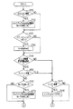
図3及び図4は、バックアップRAM54へのエンジン水温の記憶処理手順を示すフローチャートである。この処理は、例えば所定周期で繰り返し実行される。
【0061】
この一連の処理においては、図3に示すように、上記ECU50の起動直後において上記バックアップRAM54のエンジン水温の記憶箇所に記憶された値を上記N−RAM53にコピーする(ステップ200,210)。なお、イグニッションスイッチのオフ状態からオン状態への切り替え時には、上記N−RAM53の記憶値が「0」とされる(ステップ220,230)。
【0062】
こうした処理の後に、ステップ240においてECU50起動後所定時間αが経過したか否かが、またステップ250においてプレヒート処理が実施されたか否かが判定される。ここで、所定時間αは、上記水温センサ71によるエンジン水温の検出が安定する時間に設定してある。また、ステップ250の処理は、プレヒート処理に先立ち、バックアップRAM54にエンジン水温を記憶するようにするために行うものである。
【0063】
そして、ECU起動後所定時間αが経過し、且つプレヒート処理が実施されていないときには、続くステップ260〜300の処理において、バックアップRAM54にエンジン水温を記憶する処理を行う。すなわち、上記N−RAM53の値がイグニッションスイッチがオン状態とされることで「0」とされている場合には、バックアップRAM54のエンジン水温の記憶箇所に記憶された値をN−RAM53にコピーする(ステップ260,270)。また、エンジン始動がなされたかどうかが判断される(図4,ステップ280)。そして、エンジン始動がなされていないときには、N−RAM53の値がバックアップRAM54を初期化するときに用いる初期値であるかどうかが判断され(図4、ステップ290)、同初期値であるときには、バックアップRAM300に水温センサ71によるエンジン水温を記憶する(図4、ステップ300)。
【0064】
一方、上記ステップ240で所定時間αが経過していないと判断された場合やプレヒート処理が実施された場合には、ステップ310でエンジン10が始動されたか否かが判断される。
【0065】
そして、このステップ310や上記ステップ280において、エンジンが始動されたと判断されると、エンジンが起動された旨の履歴を保持すべくエンジンONフラグをオンとする(ステップ320,330)。
【0066】
こうした一連の処理の後に、エンジンが起動した旨の履歴があり、且つイグニッションスイッチがオンからオフに切り替えられた場合には、バックアップRAM54の記憶値を初期値とし(ステップ340,350)、この処理を一旦終了する。
【0067】
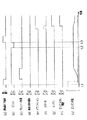
ここで、こうした処理手順によるバックアップRAM54へのエンジン水温の記憶態様について、図5及び図6を参照して更に説明する。
図5及び図6は、同処理にかかるタイムチャートである。
【0068】
すなわち、図5(a)に示すように、時刻t1において運転席のドアが開操作されると、ECU50が起動される(図5(b))。そして、ECU50の起動から所定時間αが経過する時刻t2において、バックアップRAMに記憶されているエンジン水温(図5(i)の一点鎖線)が、初期値であることに基づいて同初期値を上記水温センサ71によって検出されたエンジン水温(図5(i)の実線)に書き換えられる。
【0069】
このバックアップRAMのエンジン水温記憶箇所の記憶値を検出されたエンジン水温に書き換える操作は、時刻t3において、プレヒート処理(図5(c))が実施されるまで行われる。このように、プレヒート処理が実施されるまで、バックアップRAMの上記記憶値が書き換えられ続けるのは、先の図4のステップ290の処理による。すなわち、N−RAM53のエンジン水温値がバックアップRAMの記憶値の更新を許可する初期値であるために、更新が許容され続ける。
【0070】
そして、プレヒート処理が終了し(図5(c))、イグニッションスイッチがオンとされ(図5(e))、スタータの起動(図5(f)、及びエンジンの起動(図5(g))がなされると、エンジンONのフラグがオンとされる(図5(h)。
【0071】
一方、時刻t4にイグニッションスイッチがオフとされる(図5(e))ことで、エンジンが停止される(図5(g))と、上記ECU50では、後処理が終了するまで起動状態を保持する(図5(b))。すなわち、エンジン水温が蓄熱器内水温よりも高い場合には、エンジン10の冷却水を上記蓄熱器31に回収する(図5(d))。また、イグニッションオフとエンジンONフラグのオン状態との論理積に基づいてバックアップRAM54のエンジン水温の記憶箇所に記憶された値を初期化する(図5(i))。
【0072】
このバックアップRAM54のエンジン水温の記憶箇所に記憶された値の初期化がなされた後、エンジンONフラグをオフとして(図5(h))からECU50は停止する(図5(b))。
【0073】
また、図6(a)に示すように、時刻t1での運転席のドアの開操作に伴うECU50の起動(図6(b))、プレヒート処理(図6(c))がなされた後に、イグニッションがオン状態とされることがなく、時刻t2においてECU50が停止された(図5(b))直後の時刻t3にドアの開操作が再度なされた(図6(a))としても、バックアップRAM54の記憶値の更新条件が満たされないために、同バックアップRAM54はプレヒート処理前の値を保持することができる。
【0074】
このように、本実施形態によれば、バックアップRAM54には、プレヒート処理前のエンジン水温を的確に保持することができる。そして、このバックアップRAM54に記憶保持されたエンジン水温を用いることで、エバポパージシステムの異常診断を的確に行うことができる。
【0075】
以下、本実施形態のエバポパージシステムの異常診断処理について図7を参照して説明する。
図7は、同エバポパージシステムの異常診断処理の手順を示すフローチャートである。
【0076】
この一連の処理においては、エンジン始動後、バックアップRAMに記憶されたエンジン水温を読み込み、同エンジン水温と上記吸気温センサ82によって検出された吸気温とに基づいて上記燃料タンク40の暖機態様を診断する(ステップ400,410,420)。
【0077】
そして、上記エンジン水温及び吸気温に基づいて燃料タンクの温度が所定温度以下であると推定される場合には(ステップ430)、エバポパージシステムの異常診断を許可する。この場合、所定時間の経過を待ってタンク内圧を検出し、これに基づいてエバポパージシステムの異常診断を行う(ステップ440,450)。
【0078】
以上説明した本実施形態によれば、以下の効果が得られるようになる。
(1)エンジン10のプレヒート処理に先立ち、エンジン水温を検出し、これを記憶保持した。そして、プレヒート後にこの記憶保持したエンジン水温を用いることで、燃料タンク40内の燃料の暖機態様を的確に把握することができる。
【0079】
(2)プレヒートに先立ちエンジン水温を特にバックアップRAM54に記憶することで、イグニッションスイッチのオン操作によってN−RAM53が初期化される場合であれ、同エンジン水温を好適に保持することができる。
【0080】
(3)エンジン稼働中においてイグニッションスイッチがオン状態からオフ状態に切り替えられたときに、バックアップRAM54のエンジン水温を予め設定した所定値に初期化した。更に、同バックアップRAM54に記憶されている値がこの初期化された値であることを条件に、エンジン水温をバックアップRAM54へ記憶することとした。これにより、例えばイグニッションスイッチがオンとされないために、プレヒート後に一旦ECU50が停止され、その後短期間の後に再度同ECUが起動された場合であれ、プレヒート前のエンジン水温を的確に保持することができる。
【0081】
(4)エンジン始動のための予備操作として、イグニッションスイッチのオン操作及び運転席ドアの開操作を検知し、これに基づいて、ECU50の起動やバックアップRAM54へのエンジン水温の記憶、プレヒート処理を行う構成とした。これにより、これら一連の操作を迅速に行うことができる。
【0082】
(5)プレヒート処理の終了前にはエンジン10の始動を禁止した。これにより、十分に暖機した状態でエンジン10を始動することができる。
なお、上記実施形態は、以下のように変更して実施してもよい。
【0083】
・蓄熱装置に用いる熱媒体としては、冷却水に限らず、例えば油であってもよい。
・プレヒート処理は、必ずしも上記処理に限らず、例えばイグニッションキー等の操作により運転者によるエンジン始動の意志が表明された場合には、エンジン始動を優先させるものであってもよい。
【0084】
・バックアップRAM54へのエンジン水温の記憶態様については、上記処理にも限られない。例えば、N−RAM53に一旦バックアップRAM54の保持するエンジン水温をコピーし、これ予め設定された所定値であるときにバックアップRAM54にエンジン水温を記憶する代わりに、バックアップRAM54に記憶されているエンジン水温が予め設定された所定値であるときにエンジン水温を記憶するようにしてもよい。
【0085】
・エンジンONフラグを用いなくても、エンジン稼働中にイグニッションがオン状態からオフ状態へと切り替えられた状態を検知することができるなら、これに基づいてバックアップRAM54の初期化を行ってもよい。
【0086】
・バックアップRAM54へのエンジン水温の書き込みは、同RAM54に記憶保持されるエンジン水温が予め設定された所定値であることをもって行うものにも限らない。例えば、エンジン始動のための予備操作が検知されることを条件にエンジン水温をバックアップRAM54に書き込んだ後には、所定期間、同値の更新を禁止するようにしてもよい。
【0087】
・また、例えばエンジン始動のための予備操作が検知されたときにバックアップRAM54へエンジン水温を記憶するようにしても、例外的な操作がなければプレヒート前のエンジン水温を的確に保持することができる。
【0088】
・エンジン始動のための予備操作の検知としては、上記のものにも限らず、運転席側以外のドアの開操作を含めてもよい。また、ドアロックを遠隔操作によって解除する装置、いわゆるキーレスを備えたものにおいては、このキーレスによるドアロックの解除処理がなされたときを検知してもよい。
【0089】
・また、遠隔操作によってエンジン始動の指令がなされるものにあっては、同指令がなされた後、同エンジン始動はもとより、プレヒート処理に先だって、バックアップRAM54へのエンジン水温の記憶処理を行ってもよい。
【0090】
・バッテリ61による給電状態が常時維持されるバックアップRAM54の代わりに、例えばEEPROM(Electrically Erasable Programable Read Only Memory)等、任意の不揮発性のメモリを用いてもよい。
【0091】
・上記エバポパージシステムの異常診断装置に限らず、例えば、エンジンの排気系に設けられる触媒の劣化を検出する装置等において、その触媒の暖機態様の診断に際しても本発明の適用は有効である。要は、エンジンを暖機する蓄熱装置を備えたエンジンシステムにおいて、同システムの各箇所の暖機診断を行う任意のエンジンシステムの診断装置に本発明を適用することができる。
【図面の簡単な説明】
【図1】本発明にかかるエンジンシステムの診断装置をエバポパージシステムの異常診断装置に適用した一実施形態についてその全体構成を示す図。
【図2】同実施形態のプレヒート処理の手順を示すフローチャート。
【図3】同実施形態におけるプレヒート処理前のエンジン水温の記憶処理手順を示すブローチャート。
【図4】同実施形態におけるプレヒート処理前のエンジン水温の記憶処理手順を示すブローチャート。
【図5】同実施形態におけるプレヒート処理前のエンジン水温の記憶態様の一例を示すタイムチャート。
【図6】上記エンジン水温の記憶態様の別の例を示すタイムチャート。
【図7】同実施形態のエバポパージシステムの異常診断手順を示すフローチャート。
【符号の説明】
10…エンジン、11…吸気通路、21…ウォータポンプ、22…バイパス通路、23…冷却通路、24…ラジエータ、25…サーモスタット、31…蓄熱器、31a、31b…ワンウェイバルブ、32…暖機通路、33…電動ポンプ、40…燃料タンク、41…キャニスタ、41a…吸着材、41b…大気弁、41c…大気導入弁、42…ベーパ通路、43…パージ通路、44…パージ制御弁、50…電子制御装置、51…中央演算装置、52…ROM、53…RAM、61…バッテリ。[0001]
BACKGROUND OF THE INVENTION
The present invention relates to a diagnosis device for an engine system, and more particularly, in an engine system including a heat storage device for storing a heat medium for warming up an engine at least during cold start, a diagnosis for diagnosing the warm-up mode of each part of the system Relates to the device.
[0002]
[Prior art]
2. Description of the Related Art Conventionally, as an engine system, there is an evaporation purge system in which fuel vapor (evaporation) generated in a fuel tank is collected in a canister, and the collected fuel vapor is appropriately purged from the canister to an intake passage. is there.
[0003]
Such an evaporative purge system usually includes a canister that collects fuel vapor generated in a fuel tank, a vapor passage that communicates the fuel tank and the canister, and a purge passage that communicates the canister and the intake passage. Configured as In the system, a purge control valve capable of opening / closing control is provided in the middle of the purge passage, and the canister is provided with an air introduction valve capable of introducing air.
[0004]
On the other hand, regarding the above-described evaporation purge system, there is an abnormality diagnosis apparatus for the evaporation purge system that diagnoses the presence or absence of leakage due to a hole in the evaporation path or a laceration. The abnormality diagnosis basically shuts off the introduction of the atmosphere into the canister and disconnects the purge path from the intake passage of the engine to make the purge path into an isolated space. The presence or absence of abnormality is diagnosed based on the pressure change.
[0005]
That is, when there is a leak in the evaporation purge system, the inside of the purge path is connected to the atmosphere, so that the pressure in the evaporation path converges to atmospheric pressure. On the other hand, when there is no leakage in the evaporation purge system, the vaporized fuel in the evaporation path converges to the saturated vapor pressure, so the evaporation path internal pressure is the same as the convergence value and the vaporized fuel in the evaporation path. It converges to the sum of the gas partial pressure values. Thus, the presence or absence of an abnormality in the evaporation purge system can be diagnosed based on the difference in the change in the evaporation path internal pressure due to these two factors.
[0006]
However, the actual pressure change mode in the evaporation path does not depend only on the presence or absence of leakage in the evaporation path, but depends on various parameters. For example, when there is no hole in the evaporation path, when the temperature in the evaporation path is high, the saturated vapor pressure also increases, so the evaporation path internal pressure tends to be higher than when the temperature in the path is low. . As described above, since the pressure in the evaporation path is affected by various parameters, there is not necessarily a clear difference depending on the presence or absence of leakage in the same path. As a result, the abnormality diagnosis of the evaporation purge system can be performed accurately. May not be possible.
[0007]
In view of this, conventionally, for example, as disclosed in Japanese Patent Application Laid-Open No. 6-81728, a proposal has been made to perform such abnormality diagnosis of the evaporation purge system only when the engine is cold started. In other words, when the engine is cold started, the partial pressure of vaporized fuel in the evaporation path is small, so that the influence of the vaporized fuel on the evaporation path internal pressure can be suitably suppressed. It can be carried out.
[0008]
[Problems to be solved by the invention]
On the other hand, for the purpose of promoting warm-up of the engine at the cold start, etc., proposals have been made to provide a heat storage device in the engine coolant system. This heat storage device includes, for example, a passage that circulates cooling water to the engine, a heat accumulator that keeps and stores the cooling water that circulates through the passage, and an electric pump that circulates the cooling water between the engine and the heat accumulator. By providing such a heat storage device and storing high-temperature cooling water in the regenerator, engine warm-up can be promoted by the cooling water (heat medium) stored in the regenerator during cold start. .
[0009]
However, when the abnormality diagnosis device for the evaporation purge system is applied to an engine equipped with the heat storage device, the abnormality diagnosis by the abnormality diagnosis device cannot be performed accurately. That is, since the engine is warmed up by the heat storage device, the device does not satisfy the conditions for performing abnormality diagnosis of the evaporation purge system. However, when the engine is warmed up by the heat storage device, the fuel tank is not always warmed up sufficiently. Therefore, although the engine is warmed up by the heat storage device, the abnormality of the evaporation purge system is actually diagnosed. Sometimes it is possible to do exactly. Eventually, when the control for warming up the engine is performed in advance by the heat storage device before starting, it is determined that the abnormality diagnosis condition is not satisfied even though the condition for abnormality diagnosis of the evaporation purge system is in place. Doing so may prevent accurate diagnosis of abnormalities.
[0010]
In addition, not only the abnormality diagnosis of the evaporation purge system described above, but also in the warm-up diagnosis in an engine system equipped with a heat storage device that warms up the engine prior to starting, such a situation in which misdiagnosis of the diagnosis condition is concerned is generally common It has become a thing.
[0011]
The present invention has been made in view of the above circumstances, and an object of the present invention is to provide an engine system diagnosis apparatus that can perform a more accurate warm-up diagnosis in an engine system including a heat storage device. is there.
[0012]
[Means for Solving the Problems]
In the following, means for achieving the above object and its effects are described.
The invention according to
[0013]
In the above configuration, prior to engine warm-up, the engine warm-up mode is detected and the detection result is stored and retained. At least one of an evaporative purge system and the catalyst Diagnose warm-up mode. For this reason, the engine warm-up mode before the engine warm-up by the heat storage device can be grasped even after the engine warm-up by the heat storage device. Evaporative purge system and at least one of the catalysts The warm-up diagnosis can be performed more accurately.
According to a second aspect of the present invention, in the engine system diagnosis apparatus according to the first aspect, the diagnosis unit is configured to detect the intake air temperature of the engine and the warm-up state detection unit after the engine is warmed up by the heat storage device. Based on the warm-up mode of the stored engine Evaporative purge system and at least one of the catalysts The gist of this is to diagnose the warm-up mode.
The gist of a third aspect of the invention is the engine system diagnostic apparatus according to the first or second aspect, wherein the diagnostic means diagnoses a warm-up mode of the engine after the engine is started.
[0014]
The
[0015]
In this manner, if the nonvolatile memory is stored and held, the detection result of the engine warm-up mode before the engine warm-up by the heat storage device can be suitably stored and held.
[0016]
Claim 5 The described invention is claimed. 4 The warm-up state detection means may detect the warm-up mode when the preliminary operation is detected by the detection means. The detection means detects a preliminary operation for starting the engine. The gist of this is to store and hold the detection results.
[0017]
According to the above configuration, when a preliminary operation for starting the engine is detected, it is possible to perform these processes quickly by detecting the warm-up mode and storing and storing the detection result. Become.
[0018]
Claim 6 The described invention is claimed. 4 In the described invention, the warm-up mode detection unit further includes a detection unit that detects a preliminary operation for starting the engine, and the warm-up mode detection unit is stored in the nonvolatile memory based on an ignition switch being turned off during operation of the engine. Initializing means for initializing the value stored and retained, the detection means detects the preliminary operation, and the condition that the value stored and retained in the nonvolatile memory is the initial value, The gist of the present invention is to include rewriting means for rewriting the initial value based on the detection result.
[0019]
When the warm-up mode of the engine is detected by detecting the preliminary operation for starting the engine and stored in the nonvolatile memory, the preliminary operation for starting the engine is repeated many times in a short time. If it is repeated, the detection result stored in the same memory may be updated each time. In this case, the detection result of the engine warm-up mode after the engine warm-up by the heat storage device may be stored in the nonvolatile memory.
[0020]
In this regard, in the above configuration, the detection result of the engine warm-up mode is stored and held in the nonvolatile memory based on the history of the ignition switch being turned off during engine operation. For this reason, even if the preliminary operation for starting the engine is repeated in a short time, it is possible to avoid updating the stored value of the nonvolatile memory in conjunction with the preliminary operation.
[0021]
Claim 7 The described invention is claimed. 5 Or 6 In the described invention, after the preliminary operation is detected by the detection means, when the engine is not warmed up more than a predetermined amount, warm-up by the heat storage device is allowed, and start of the engine is prohibited until the warm-up is completed. The gist of the invention is to further include means for performing the above.
[0022]
According to the above configuration, the engine can be quickly warmed up by the heat storage device. Further, according to the above configuration, the engine start is prohibited until the engine warm-up is completed, so that the engine start can be suitably performed.
[0023]
The above claims 5 ~ 7 The invention according to any one of claims 8 As described above, the detection means detects at least one of an opening operation of a door of a vehicle on which the engine is mounted and an ON operation of an ignition switch as a preliminary operation for starting the engine. You may do it.
[0025]
DETAILED DESCRIPTION OF THE INVENTION
Hereinafter, an embodiment in which a diagnosis device for an engine system according to the present invention is applied to an abnormality diagnosis device for an evaporation purge system will be described with reference to the drawings.
[0026]
FIG. 1 shows the overall configuration of an abnormality diagnosis apparatus for an evaporation purge system according to this embodiment.
The
[0027]
A
[0028]
Further, the system includes the following as a heat storage device to warm up the
[0029]
Here, the
[0030]
Next, the evaporation purge system in the above system will be described.
The evaporation purge system includes the following. First, a
[0031]
Here, the canister 41 is provided with an adsorbent (activated carbon) 41a that adsorbs fuel vapor and temporarily stores it. The fuel vapor adsorbed on the adsorbent 41a is re-detached when the internal space of the canister 41 is depressurized.
[0032]
In order to accurately adsorb and re-detach the fuel vapor into the canister 41, the evaporation purge system includes the following. First, the canister 41 is provided with an atmospheric valve 41b that opens when the pressure in the canister 41 reaches a predetermined pressure higher than the atmospheric pressure and discharges excess air in the canister 41. . The
[0033]
The fuel vapor adsorbed by the adsorbent 41a in the canister 41 is released again when the inside of the canister 41 is depressurized by opening control of the
[0034]
Further, the engine system supplies power to the ECU 50, an electronic control unit (hereinafter referred to as ECU) 50, a part for detecting a preliminary operation for starting the engine, and the ECU 50 to control the
[0035]
Here, ECU50 is provided with the following. First, a central processing unit (CPU) 51 that performs various calculations while referring to detection results of the various sensors described above, and a
[0036]
Here, since power is always supplied to the
[0037]
The power supply to the ECU 50 is started by detecting a preliminary operation for starting the
[0038]
Specifically, in the present embodiment, a
[0039]
Here, the
[0040]
On the other hand, the
When a preliminary operation for starting the
[0041]
Specifically, the warm-up mode of the
[0042]
However, even if a preliminary operation for starting the
[0043]
When stopping the power supply to the ECU 50, it may be desirable to recover the high-temperature cooling water supplied from the
[0044]
In order to perform such a series of controls, in the present embodiment, a
[0045]
Here, the procedure of the preheating process performed when power supply to the ECU 50 is started by detecting a preliminary operation for starting the
[0046]
FIG. 2 is a flowchart showing the preheat processing procedure. This process is repeatedly executed at predetermined intervals, for example.
In this series of processes, first, in
[0047]
If it is determined that the preheat condition is satisfied, the control is executed until it is determined that the
[0048]
When the preheating process is thus completed, the
[0049]
On the other hand, when the preheat start condition is not satisfied at
[0050]
In the present embodiment, even when the power supply to the ECU 50 is stopped by turning off the ignition switch or the like, if the engine water temperature is higher than the water temperature in the regenerator, the cooling water for the
[0051]
Next, abnormality diagnosis of the evaporation purge system in the present embodiment will be described.
The abnormality diagnosis of the evaporation purge system is basically performed by closing the
[0052]
In this case, when there is no leakage in the evaporation path, the fuel in the
[0053]
In order to grasp the warm-up mode of the fuel in the
[0054]
Therefore, in this embodiment, prior to the preheating process, the warm-up mode of the
[0055]
Furthermore, in this embodiment, for example, when the opening and closing of the door on the driver's seat side is repeated, the engine water temperature stored in the
[0056]
Specifically, the storage location of the engine water temperature in the
[0057]
Specifically, this history is held as the
[0058]
In the present embodiment, whether or not to update the value stored in the storage location of the engine water temperature in the
[0059]
In order to perform the above-described series of processing, in the present embodiment, a
[0060]
Here, the storage processing of the engine water temperature in the
FIGS. 3 and 4 are flowcharts showing the storage processing procedure of the engine water temperature in the
[0061]
In this series of processes, as shown in FIG. 3, immediately after the ECU 50 is started, the value stored in the storage location of the engine water temperature in the
[0062]
After such processing, it is determined in
[0063]
And when predetermined time (alpha) passes after ECU starting and the preheating process is not implemented, the process which memorize | stores engine water temperature in backup RAM54 is performed in the process of subsequent steps 260-300. That is, when the value of the N-
[0064]
On the other hand, if it is determined in
[0065]
If it is determined in
[0066]
After such a series of processing, if there is a history that the engine has been started and the ignition switch is switched from on to off, the stored value in the
[0067]
Here, the storage mode of the engine water temperature in the
5 and 6 are time charts related to the processing.
[0068]
That is, as shown in FIG. 5 (a), when the driver's seat door is opened at time t1, the ECU 50 is activated (FIG. 5 (b)). Then, at the time t2 when the predetermined time α elapses from the activation of the ECU 50, the initial value is set based on the fact that the engine water temperature (the dashed line in FIG. 5 (i)) stored in the backup RAM is the initial value. The engine water temperature detected by the
[0069]
The operation of rewriting the stored value of the engine water temperature storage location in the backup RAM to the detected engine water temperature is performed at time t3 until the preheating process (FIG. 5C) is performed. As described above, the stored value in the backup RAM is continuously rewritten until the preheating process is performed, according to the process in
[0070]
Then, the preheating process is completed (FIG. 5C), the ignition switch is turned on (FIG. 5E), the starter is started (FIG. 5F), and the engine is started (FIG. 5G). Is performed, the engine ON flag is turned on (FIG. 5 (h)).
[0071]
On the other hand, when the engine is stopped (FIG. 5 (g)) by turning off the ignition switch at time t4 (FIG. 5 (e)), the ECU 50 maintains the activated state until the post-processing is completed. (FIG. 5B). That is, when the engine water temperature is higher than the water temperature in the regenerator, the cooling water of the
[0072]
After the value stored in the storage location of the engine water temperature in the
[0073]
Further, as shown in FIG. 6 (a), after the ECU 50 is activated (FIG. 6 (b)) and the preheating process (FIG. 6 (c)) in association with the opening operation of the driver's seat door at time t1, Even if the ignition is not turned on and the ECU 50 is stopped at time t2 (FIG. 5B) and the door opening operation is performed again at time t3 (FIG. 6A), the backup is performed. Since the update condition of the stored value of the
[0074]
Thus, according to the present embodiment, the
[0075]
Hereinafter, the abnormality diagnosis process of the evaporation purge system of this embodiment will be described with reference to FIG.
FIG. 7 is a flowchart showing a procedure of abnormality diagnosis processing of the evaporation purge system.
[0076]
In this series of processing, after the engine is started, the engine water temperature stored in the backup RAM is read, and the
[0077]
If the temperature of the fuel tank is estimated to be equal to or lower than the predetermined temperature based on the engine water temperature and the intake air temperature (step 430), abnormality diagnosis of the evaporation purge system is permitted. In this case, the tank internal pressure is detected after a lapse of a predetermined time, and an abnormality diagnosis of the evaporation purge system is performed based on this (steps 440 and 450).
[0078]
According to the embodiment described above, the following effects can be obtained.
(1) Prior to the preheating process of the
[0079]
(2) By storing the engine water temperature in the
[0080]
(3) When the ignition switch is switched from the on state to the off state during engine operation, the engine water temperature in the
[0081]
(4) As a preliminary operation for starting the engine, an ON operation of the ignition switch and an opening operation of the driver's seat door are detected. Based on this, activation of the ECU 50, storage of the engine water temperature in the
[0082]
(5) Before starting the preheating process, the
The above embodiment may be modified as follows.
[0083]
-The heat medium used for the heat storage device is not limited to cooling water, but may be oil, for example.
The preheating process is not necessarily limited to the above process. For example, when the driver's intention to start the engine is expressed by operating an ignition key or the like, the engine starting may be prioritized.
[0084]
The storage mode of the engine water temperature in the
[0085]
Even if the engine ON flag is not used, if the state where the ignition is switched from the on state to the off state during engine operation can be detected, the
[0086]
The writing of the engine water temperature to the
[0087]
Further, for example, even if the engine water temperature is stored in the
[0088]
The detection of the preliminary operation for starting the engine is not limited to the above, and may include an opening operation of a door other than the driver's seat side. In addition, in a device that releases a door lock by remote operation, that is, a device equipped with a so-called keyless, it may be detected when the doorless unlocking process is performed.
[0089]
-If the engine start command is issued by remote control, the engine water temperature is stored in the
[0090]
Instead of the
[0091]
The present invention is not limited to the abnormality diagnosis device for the evaporation purge system, and the present invention is also effective for diagnosing the warm-up mode of the catalyst in, for example, a device for detecting deterioration of the catalyst provided in the exhaust system of the engine. . In short, in an engine system provided with a heat storage device for warming up the engine, the present invention can be applied to a diagnostic device for any engine system that performs warm-up diagnosis at each location of the system.
[Brief description of the drawings]
FIG. 1 is a diagram showing the overall configuration of an embodiment in which a diagnosis device for an engine system according to the present invention is applied to an abnormality diagnosis device for an evaporation purge system.
FIG. 2 is a flowchart showing a preheat processing procedure according to the embodiment;
FIG. 3 is a blow chart showing a storage processing procedure of engine water temperature before preheating processing in the same embodiment;
FIG. 4 is a blow chart showing a storage processing procedure of engine water temperature before preheating processing in the same embodiment;
FIG. 5 is a time chart showing an example of a storage mode of engine water temperature before preheating processing in the same embodiment.
FIG. 6 is a time chart showing another example of the storage mode of the engine water temperature.
FIG. 7 is a flowchart showing an abnormality diagnosis procedure of the evaporation purge system of the embodiment.
[Explanation of symbols]
DESCRIPTION OF
Claims (8)
前記蓄熱装置による前記エンジンの暖機に先立ち、同エンジンの暖機態様の検出及び該検出結果の記憶保持を行う暖機状態検出手段と、前記蓄熱装置による前記エンジンの暖機後に、前記暖機状態検出手段によって記憶保持された前記エンジンの暖機態様に基づいて前記エンジンの暖機後における前記エバポパージシステム及び前記触媒の少なくとも一方の暖機態様の診断を行う診断手段とを備えることを特徴とするエンジンシステムの診断装置。Prior to engine start-up, an apparatus for diagnosing the warm-up mode of at least one of an evaporation purge system in an engine system equipped with a heat storage device and a catalyst provided in the exhaust system of the engine to warm it up,
Prior to warm-up of the engine by the heat storage device, warm-up state detection means for detecting the warm-up mode of the engine and storing the detection result, and after warming up the engine by the heat storage device, And a diagnostic means for diagnosing the warm-up mode of at least one of the evaporation purge system and the catalyst after warming-up of the engine based on the warm-up mode of the engine stored and held by the state detection means. An engine system diagnostic device.
請求項1記載のエンジンシステムの診断装置。After the engine is warmed up by the heat storage device, the diagnostic means is configured to determine whether the evaporation purge system and the catalyst are based on the engine intake temperature and the warm-up state of the engine stored by the warm-up state detection means. The diagnosis device for an engine system according to claim 1, wherein diagnosis of at least one of warm-up modes is performed.
前記診断手段は、前記エンジンの始動後に同エンジンの暖機態様の診断を行う
ことを特徴とするエンジンシステムの診断装置。The engine system diagnostic apparatus according to claim 1 or 2,
The diagnosis device for an engine system, wherein the diagnosis means diagnoses a warm-up mode of the engine after the engine is started.
請求項1〜3のいずれかに記載のエンジンシステムの診断装置。The engine system diagnosis device according to any one of claims 1 to 3, wherein the warm-up mode detection unit stores and holds the detection result in a nonvolatile memory.
前記エンジンの始動のための予備操作を検知する検知手段を更に備え、
前記暖機状態検出手段は、前記検知手段により前記予備操作が検知されたときに前記暖機態様の検出及び該検出結果の記憶保持を行う
ことを特徴とするエンジンシステムの診断装置。The engine system diagnosis apparatus according to claim 4, wherein
A detecting means for detecting a preliminary operation for starting the engine;
The engine warming-up state detection unit detects the warming-up mode and stores the detection result when the preliminary operation is detected by the detection unit.
前記エンジンの始動のための予備操作を検知する検知手段を更に備え、
前記暖機態様検出手段は、エンジン稼働中にイグニッションスイッチが切られたことに基づいて前記不揮発性メモリに記憶保持される値を初期化する初期化手段と、前記検知手段により前記予備操作が検知されたこと、及び前記不揮発性メモリに記憶保持されている値が初期値であることを条件に、前記初期値の前記検出結果による書き換えを行う書換手段とを備える
ことを特徴とするエンジンシステムの診断装置。The engine system diagnosis apparatus according to claim 4, wherein
A detecting means for detecting a preliminary operation for starting the engine;
The warm-up mode detection means detects an initializing means for initializing a value stored in the nonvolatile memory based on the ignition switch being turned off while the engine is operating, and the preliminary operation is detected by the detection means. And a rewriting means for rewriting the initial value based on the detection result on the condition that the value stored in the nonvolatile memory is an initial value. Diagnostic device.
前記検知手段による前記予備操作の検知後にエンジンが所定以上暖機されていないときに前記蓄熱装置による暖機を許容するとともに、同暖機が完了するまで前記エンジンの始動を禁止する手段を更に備える
ことを特徴とするエンジンシステムの診断装置。The engine system diagnostic apparatus according to claim 5 or 6,
The engine further includes means for permitting warm-up by the heat storage device when the engine is not warmed up more than a predetermined amount after detection of the preliminary operation by the sensing means, and prohibiting starting of the engine until the warm-up is completed. A diagnostic device for an engine system.
請求項5〜7のいずれかに記載のエンジンシステムの診断装置。The detection means detects at least one of an opening operation of a door of a vehicle on which the engine is mounted and an ON operation of an ignition switch as a preliminary operation for starting the engine. A diagnostic apparatus for an engine system according to claim 1.
Priority Applications (2)
| Application Number | Priority Date | Filing Date | Title |
|---|---|---|---|
| JP2001106165A JP4228551B2 (en) | 2001-04-04 | 2001-04-04 | Engine system diagnostic device |
| US10/101,879 US6820471B2 (en) | 2001-04-04 | 2002-03-21 | Engine system diagnosing apparatus and method |
Applications Claiming Priority (1)
| Application Number | Priority Date | Filing Date | Title |
|---|---|---|---|
| JP2001106165A JP4228551B2 (en) | 2001-04-04 | 2001-04-04 | Engine system diagnostic device |
Publications (2)
| Publication Number | Publication Date |
|---|---|
| JP2002303196A JP2002303196A (en) | 2002-10-18 |
| JP4228551B2 true JP4228551B2 (en) | 2009-02-25 |
Family
ID=18958719
Family Applications (1)
| Application Number | Title | Priority Date | Filing Date |
|---|---|---|---|
| JP2001106165A Expired - Lifetime JP4228551B2 (en) | 2001-04-04 | 2001-04-04 | Engine system diagnostic device |
Country Status (2)
| Country | Link |
|---|---|
| US (1) | US6820471B2 (en) |
| JP (1) | JP4228551B2 (en) |
Families Citing this family (19)
| Publication number | Priority date | Publication date | Assignee | Title |
|---|---|---|---|---|
| JP2004052672A (en) * | 2002-07-19 | 2004-02-19 | Toyota Motor Corp | Hybrid vehicle and control method thereof |
| DE10306145A1 (en) * | 2003-02-14 | 2004-08-26 | Robert Bosch Gmbh | Direct start method for an internal combustion engine (ICE) injects fuel directly into the ICE's combustion chambers filled with air |
| JP4450185B2 (en) * | 2003-08-08 | 2010-04-14 | 株式会社デンソー | Electronic control unit |
| US7367291B2 (en) * | 2004-07-23 | 2008-05-06 | General Electric Co. | Locomotive apparatus |
| JP2007023933A (en) * | 2005-07-19 | 2007-02-01 | Mitsubishi Electric Corp | Control device for internal combustion engine |
| US20090112394A1 (en) * | 2007-10-30 | 2009-04-30 | Sosy Technologies Stu, Inc. | Apparatus for collecting, storing and transmitting vehicle information |
| US8727050B2 (en) * | 2009-02-25 | 2014-05-20 | GM Global Technology Operations LLC | System and method for controlling an electrically heated catalyst for a hybrid vehicle |
| US8413423B2 (en) * | 2009-09-01 | 2013-04-09 | GM Global Technologies Operations LLC | Catalyst temperature control systems and methods for hybrid vehicles |
| US9458812B2 (en) * | 2009-09-02 | 2016-10-04 | GM Global Technology Operations LLC | Engine control systems and methods for minimizing fuel consumption |
| US9410458B2 (en) * | 2009-10-01 | 2016-08-09 | GM Global Technology Operations LLC | State of charge catalyst heating strategy |
| JP5742964B2 (en) * | 2011-11-22 | 2015-07-01 | トヨタ自動車株式会社 | Exhaust gas purification device for internal combustion engine |
| CN103291524A (en) * | 2013-05-27 | 2013-09-11 | 江苏柳工机械有限公司 | Detecting device of diesel engine flame preheating system |
| KR101490907B1 (en) * | 2013-06-07 | 2015-02-06 | 현대자동차 주식회사 | Cold starting device and cold starting method for vehicle |
| DE102014211529B4 (en) * | 2014-06-17 | 2016-02-18 | Ford Global Technologies, Llc | Method and device for operating a heat accumulator in a motor vehicle |
| US10337438B2 (en) * | 2015-10-01 | 2019-07-02 | GM Global Technology Operations LLC | Push-button start system fault diagnosis |
| US10361553B1 (en) * | 2018-01-25 | 2019-07-23 | Gerald Laughter | Battery interrupter |
| WO2021010142A1 (en) * | 2019-07-12 | 2021-01-21 | パナソニックIpマネジメント株式会社 | Onboard storage system |
| CN115143007A (en) * | 2021-03-30 | 2022-10-04 | 广州汽车集团股份有限公司 | A temperature control module control method, device and computer storage medium |
| JP7500492B2 (en) * | 2021-04-26 | 2024-06-17 | 愛三工業株式会社 | Fault diagnosis device for fuel vapor processing device |
Family Cites Families (5)
| Publication number | Priority date | Publication date | Assignee | Title |
|---|---|---|---|---|
| US4227402A (en) * | 1978-11-14 | 1980-10-14 | Creative Tool Company | Combustion monitoring system for fuel injected engines |
| US5255733A (en) * | 1992-08-10 | 1993-10-26 | Ford Motor Company | Hybird vehicle cooling system |
| JPH10309933A (en) | 1997-05-13 | 1998-11-24 | Denso Corp | Vehicle heating system |
| JP4078742B2 (en) * | 1998-02-17 | 2008-04-23 | 株式会社デンソー | Vehicle heating system |
| WO2002037399A1 (en) * | 2000-11-03 | 2002-05-10 | Detroit Diesel Corporation | Sensor simulator for calibration and service of internal combustion engines |
-
2001
- 2001-04-04 JP JP2001106165A patent/JP4228551B2/en not_active Expired - Lifetime
-
2002
- 2002-03-21 US US10/101,879 patent/US6820471B2/en not_active Expired - Fee Related
Also Published As
| Publication number | Publication date |
|---|---|
| US20020144667A1 (en) | 2002-10-10 |
| JP2002303196A (en) | 2002-10-18 |
| US6820471B2 (en) | 2004-11-23 |
Similar Documents
| Publication | Publication Date | Title |
|---|---|---|
| JP4228551B2 (en) | Engine system diagnostic device | |
| US6629512B2 (en) | Internal combustion engine with heat accumulating device | |
| US7757649B2 (en) | Controller, cooling system abnormality diagnosis device and block heater determination device of internal combustion engine | |
| US9261012B2 (en) | Abnormality determination apparatus and abnormality determination method for coolant temperature sensor, and engine cooling system | |
| US8170779B2 (en) | Abnormality diagnosis device for exhaust heat recovery equipment | |
| JP3896288B2 (en) | Cooling system temperature estimation device | |
| US20090241863A1 (en) | Control method of engine rapid warm-up system | |
| JP4026348B2 (en) | Evaporative gas purge system leak diagnosis device | |
| US6529818B2 (en) | Control device for engine having automatic stop and start function | |
| JPH10176534A (en) | Thermostat failure detection device for engine cooling system | |
| JP2004176570A (en) | Vehicle abnormality diagnosis device | |
| JP2010065671A (en) | Failure diagnosis device of cooling system for vehicle | |
| JP5308626B2 (en) | Cooling system failure diagnosis device for internal combustion engine | |
| JP2005330955A (en) | Electronic control unit | |
| US6634219B2 (en) | Abnormality testing apparatus for engine system | |
| JP2008111414A (en) | Failure diagnosis device for engine cooling system | |
| JP2008298059A (en) | Cooling system abnormality diagnosis device and block heater determination device for internal combustion engine | |
| JP3849707B2 (en) | In-cylinder injection internal combustion engine control device | |
| US8677979B2 (en) | Method for controlling evaporation gas treating apparatus in vehicle | |
| JP2008232961A (en) | Sensor heating control device, sensor information acquisition device, and engine control system | |
| JPH11223126A (en) | Engine cooling device abnormality diagnosis device | |
| JP3765230B2 (en) | Control device for internal combustion engine | |
| JP3719515B2 (en) | Engine cooling system thermostat failure detection device | |
| JP4033141B2 (en) | Electronic control device for vehicle | |
| JP2006083800A (en) | Vehicle performing warming-up operation of engine by estimating vehicle operation start time |
Legal Events
| Date | Code | Title | Description |
|---|---|---|---|
| A621 | Written request for application examination |
Free format text: JAPANESE INTERMEDIATE CODE: A621 Effective date: 20051017 |
|
| A977 | Report on retrieval |
Free format text: JAPANESE INTERMEDIATE CODE: A971007 Effective date: 20071126 |
|
| A131 | Notification of reasons for refusal |
Free format text: JAPANESE INTERMEDIATE CODE: A131 Effective date: 20071127 |
|
| A521 | Request for written amendment filed |
Free format text: JAPANESE INTERMEDIATE CODE: A523 Effective date: 20080125 |
|
| A02 | Decision of refusal |
Free format text: JAPANESE INTERMEDIATE CODE: A02 Effective date: 20080610 |
|
| A521 | Request for written amendment filed |
Free format text: JAPANESE INTERMEDIATE CODE: A523 Effective date: 20080806 |
|
| A911 | Transfer to examiner for re-examination before appeal (zenchi) |
Free format text: JAPANESE INTERMEDIATE CODE: A911 Effective date: 20080819 |
|
| TRDD | Decision of grant or rejection written | ||
| A01 | Written decision to grant a patent or to grant a registration (utility model) |
Free format text: JAPANESE INTERMEDIATE CODE: A01 Effective date: 20081111 |
|
| A01 | Written decision to grant a patent or to grant a registration (utility model) |
Free format text: JAPANESE INTERMEDIATE CODE: A01 |
|
| A61 | First payment of annual fees (during grant procedure) |
Free format text: JAPANESE INTERMEDIATE CODE: A61 Effective date: 20081124 |
|
| R151 | Written notification of patent or utility model registration |
Ref document number: 4228551 Country of ref document: JP Free format text: JAPANESE INTERMEDIATE CODE: R151 |
|
| FPAY | Renewal fee payment (event date is renewal date of database) |
Free format text: PAYMENT UNTIL: 20111212 Year of fee payment: 3 |
|
| FPAY | Renewal fee payment (event date is renewal date of database) |
Free format text: PAYMENT UNTIL: 20111212 Year of fee payment: 3 |
|
| FPAY | Renewal fee payment (event date is renewal date of database) |
Free format text: PAYMENT UNTIL: 20121212 Year of fee payment: 4 |
|
| FPAY | Renewal fee payment (event date is renewal date of database) |
Free format text: PAYMENT UNTIL: 20131212 Year of fee payment: 5 |
|
| EXPY | Cancellation because of completion of term |