JP4026348B2 - Evaporative gas purge system leak diagnosis device - Google Patents
Evaporative gas purge system leak diagnosis device Download PDFInfo
- Publication number
- JP4026348B2 JP4026348B2 JP2001320468A JP2001320468A JP4026348B2 JP 4026348 B2 JP4026348 B2 JP 4026348B2 JP 2001320468 A JP2001320468 A JP 2001320468A JP 2001320468 A JP2001320468 A JP 2001320468A JP 4026348 B2 JP4026348 B2 JP 4026348B2
- Authority
- JP
- Japan
- Prior art keywords
- fuel
- leak
- leak diagnosis
- stopped
- combustion engine
- Prior art date
- Legal status (The legal status is an assumption and is not a legal conclusion. Google has not performed a legal analysis and makes no representation as to the accuracy of the status listed.)
- Expired - Fee Related
Links
Images


Classifications
-
- F—MECHANICAL ENGINEERING; LIGHTING; HEATING; WEAPONS; BLASTING
- F02—COMBUSTION ENGINES; HOT-GAS OR COMBUSTION-PRODUCT ENGINE PLANTS
- F02M—SUPPLYING COMBUSTION ENGINES IN GENERAL WITH COMBUSTIBLE MIXTURES OR CONSTITUENTS THEREOF
- F02M25/00—Engine-pertinent apparatus for adding non-fuel substances or small quantities of secondary fuel to combustion-air, main fuel or fuel-air mixture
- F02M25/08—Engine-pertinent apparatus for adding non-fuel substances or small quantities of secondary fuel to combustion-air, main fuel or fuel-air mixture adding fuel vapours drawn from engine fuel reservoir
- F02M25/0809—Judging failure of purge control system
-
- F—MECHANICAL ENGINEERING; LIGHTING; HEATING; WEAPONS; BLASTING
- F02—COMBUSTION ENGINES; HOT-GAS OR COMBUSTION-PRODUCT ENGINE PLANTS
- F02D—CONTROLLING COMBUSTION ENGINES
- F02D41/00—Electrical control of supply of combustible mixture or its constituents
- F02D41/02—Circuit arrangements for generating control signals
- F02D41/04—Introducing corrections for particular operating conditions
- F02D41/042—Introducing corrections for particular operating conditions for stopping the engine
Description
【0001】
【発明の属する技術分野】
本発明は、燃料タンク内の燃料が蒸発して生じたエバポガス(燃料蒸発ガス)を内燃機関の吸気系にパージ(放出)するエバポガスパージシステムのリーク診断を行うエバポガスパージシステムのリーク診断装置に関するものである。
【0002】
【従来の技術】
従来より、エバポガスパージシステムにおいては、燃料タンク内から発生するエバポガスが大気中に漏れ出すことを防止するため、燃料タンク内のエバポガスをエバポ通路を通してキャニスタ内に吸着すると共に、このキャニスタ内に吸着されているエバポガスを内燃機関の吸気系へパージするパージ通路の途中にパージ制御弁を設け、内燃機関の運転状態に応じてパージ制御弁の開閉を制御することによって、キャニスタから吸気系へパージするエバポガスのパージ流量を制御するようになっている。このエバポガスパージシステムから大気中にエバポガスが漏れる状態が長期間放置されるのを防止するために、エバポガスの漏れを早期に検出する必要がある。
【0003】
そこで、燃料タンク内の圧力(以下「タンク内圧力」という)を検出する圧力センサを設け、内燃機関の運転中にパージ制御弁を開弁して吸気系から燃料タンク内に負圧を導入した後、パージ制御弁を閉弁して、パージ制御弁から燃料タンクまでのエバポ系を密閉した状態で、タンク内圧の変化量を測定して、このタンク内圧の変化量をリーク判定値と比較することで、エバポ系のリーク(漏れ)の有無を診断するようにしたものがある。この場合、エバポ系にリークが無ければ、タンク内圧変化量は、エバポガスの発生量に応じた値となり、リーク判定値よりも小さくなるが、リークが発生していれば、タンク内圧変化量がリーク分だけ大きくなり、リーク判定値以上となる。
【0004】
一般に、リーク診断は、内燃機関の運転条件の変化の影響を受けないようにアイドル運転時や低速走行時等の安定した運転条件下で行われるため、リーク検出精度を高めるために、タンク内圧変化量の測定時間を長い時間に設定すると、内燃機関の運転中にリーク診断を開始しても、そのリーク診断の途中で、内燃機関の運転条件が変化したり、内燃機関の運転が停止されたりして、リーク診断が中止される回数が大幅に増えてしまい、内燃機関の運転中にリーク診断が最後まで行われる回数が極端に少なくなってしまう。
【0005】
そこで、米国特許第5263462号公報に示すように、内燃機関の運転停止後に、エバポ系の圧力(タンク内圧力)を検出し、その圧力に基づいてエバポ系のリークの有無を診断することが提案されている。
【0006】
【発明が解決しようとする課題】
ところが、内燃機関の運転停止後には、燃料タンクの給油口のキャップを開放して燃料を補給することがあり、給油口が開放されると、給油口からエバポ系内に大気圧が導入される。このため、内燃機関運転停止後にエバポ系の圧力に基づいてリークの有無を診断するシステムでは、給油口キャップが開放されると、エバポ系に大量のリークが発生している場合と同じように、エバポ系の圧力が大気圧付近に変化するため、リーク有りと誤診断されてしまう可能性がある。
【0007】
本発明はこのような事情を考慮してなされたものであり、従ってその目的は、給油口キャップの開放によるリークの誤診断を防止することができ、内燃機関運転停止中のリーク診断の信頼性を向上することができるエバポガスパージシステムのリーク診断装置を提供することにある。
【0008】
【課題を解決するための手段】
上記目的を達成するために、本発明の請求項1のエバポガスパージシステムのリーク診断装置は、内燃機関運転停止中に、内圧検出手段で検出したエバポ系の圧力に基づいてエバポ系のリークの有無をリーク診断手段で診断する。そして、内燃機関始動時に、それ以前の内燃機関運転停止中に燃料タンクの給油口キャップが開放されたか否かを給油口開放判定手段で判定し、内燃機関運転停止中に給油口キャップが開放されたと判定された場合には、当該内燃機関運転停止中に診断されたリーク診断結果をリーク診断結果無効手段によって無効にする。
【0009】
つまり、内燃機関始動時に、それ以前の内燃機関運転停止中に燃料タンクの給油口キャップが開放されたと判定された場合は、給油口キャップの開放による大気圧導入の影響を受けたエバポ系の圧力に基づいてリークの有無を診断した可能性があると判断して、リーク診断結果を無効にする。これにより、給油口キャップの開放によってリーク有りと誤診断してしまうことを防止することができ、内燃機関運転停止中のリーク診断の信頼性を向上することができる。
【0011】
ところで、内燃機関運転停止中に給油口キャップが開放された場合のうち、リーク診断開始前やリーク診断中に給油口キャップが開放された場合は、給油口キャップの開放による大気圧導入の影響を受けたエバポ系の圧力に基づいてリーク診断してしまうため、リーク有りと誤診断してしまう可能性が高い。しかし、内燃機関運転停止中に給油口キャップが開放された場合でも、リーク診断終了後に給油口キャップが開放された場合は、給油口キャップの開放による大気圧導入前にリーク診断を終了しているので、リーク診断結果が給油口キャップの開放の影響を受けることはない。
【0012】
このような事情を考慮して、請求項2のように、内燃機関運転停止中に燃料タンクの給油口キャップが開放されたか否かを給油口開放判定手段によって判定し、内燃機関運転停止時からリーク診断が終了する前に給油口開放判定手段で給油口キャップが開放されたと判定された場合は、リーク診断中止手段によって当該リーク診断を中止したり、或はリーク診断結果を無効にするようにしても良い。このようにすれば、リーク診断を終了する前に給油口キャップが開放されたときは、リークの有無を誤診断する可能があると判断して、リーク診断を中止したり或はリーク診断結果を無効にすることができる。一方、リーク診断終了後に給油口キャップが開放されたときは、それ以前に行われたリーク診断の結果に給油口キャップの開放が何ら影響を及ぼさないため、そのリーク診断結果をそのまま採用する。これにより、給油口キャップの開放によるリークの誤診断を防止しながら、内燃機関運転停止中に給油口キャップが開放されたときに常にリーク診断結果を無効にする場合に比べてリーク診断の頻度を多くすることができる。
【0013】
この場合、請求項3のように、内燃機関運転停止中に内圧検出手段で検出した圧力が大気圧方向に急変したときに給油口キャップが開放されたと判定するようにしても良い。つまり、給油口キャップが開放されると、給油口からエバポ系内に大気圧が一気に導入されるため、エバポ系の圧力が大気圧方向に急変する。従って、内燃機関運転停止中にエバポ系の圧力が大気圧方向に急変したときには、給油口キャップが開放されたと判定することができる。
【0014】
また、請求項4のように、給油口開放判定手段として、給油口キャップの開閉を検出するスイッチ又はセンサを設けるようにしても良い。このようにすれば、エバポ系の圧力が大気圧付近のときに給油口キャップが開放された場合や、給油量(燃料残量の増加量)が少ない場合でも、給油口キャップの開閉を正確且つ即座に検出することができる。
【0015】
或は、請求項5のように、内燃機関運転停止中に燃料残量検出手段で検出した燃料残量が所定量以上(検出誤差を越えて)増加したときに給油口キャップが開放されたと判定するようにしても良い。前述したように、燃料タンクの給油口キャップを開放して燃料を補給した場合には、燃料タンク内の燃料残量が増加するため、内燃機関運転停止中に検出した燃料残量が検出誤差を越えて増加したときには、給油口キャップが開放されたと判定することができる。
【0016】
【発明の実施の形態】
[実施形態(1)]
以下、本発明の実施形態(1)を図1乃至図5に基づいて説明する。まず、図1に基づいてエバポガスパージシステムの構成を説明する。燃料タンク11には、エバポ通路12を介してキャニスタ13が接続されている。このキャニスタ13内には、エバポガス(燃料蒸発ガス)を吸着する活性炭等の吸着体(図示せず)が収容されている。また、キャニスタ13の底面部の大気連通孔には、大気開閉弁14が取り付けられている。
【0017】
この大気開閉弁14は、常開型の電磁弁により構成され、通電がオフ(OFF)されている状態では、開弁状態に保持されて、キャニスタ13の大気連通孔が大気に開放された状態に保たれる。この大気開閉弁14は、通電すると閉弁し、キャニスタ13の大気連通孔が閉塞された状態になる。
【0018】
一方、キャニスタ13とエンジン吸気系との間には、キャニスタ13内の吸着体に吸着されているエバポガスをエンジン吸気系にパージ(放出)するためのパージ通路15が設けられ、このパージ通路15の途中に、パージ流量を制御するパージ制御弁16が設けられている。このパージ制御弁16は、常閉型の電磁弁により構成され、通電をデューティ制御することで、キャニスタ13からエンジン吸気系へのエバポガスのパージ流量を制御するようになっている。
【0019】
また、燃料タンク11には、その内圧を検出するタンク内圧センサ17(内圧検出手段)が設けられている。燃料タンク11内からパージ制御弁16までのエバポ系が密閉されている時には、燃料タンク11の内圧とエバポ系の他の部位の内圧が一致するため、タンク内圧センサ17により燃料タンク11の内圧(以下「タンク内圧」という)を検出することで、エバポ系の圧力を検出することができる。
【0020】
燃料タンク11には、燃料残量を検出する燃料レベルセンサ18(燃料残量検出手段)と燃料温度を検出する燃料温度センサ26が設けられている。その他、エンジン冷却水温を検出する水温センサ19、吸気温を検出する吸気温センサ20等の各種のセンサが設けられている。
【0021】
これら各種のセンサの出力は、制御回路21に入力される。この制御回路21の電源端子には、メインリレー22を介して車載バッテリ(図示せず)から電源電圧が供給される。この他、大気開閉弁14、パージ制御弁16及びタンク内圧センサ17に対しても、メインリレー22を介して電源電圧が供給される。メインリレー22のリレー接点22aを駆動するリレー駆動コイル22bは、制御回路21のメインリレーコントロール端子に接続され、このリレー駆動コイル22bに通電することで、リレー接点22aがオン(ON)して、制御回路21、大気開閉弁14、パージ制御弁16及びタンク内圧センサ17に電源電圧が供給される。そして、リレー駆動コイル22bへの通電をオフ(OFF)することで、リレー接点22aがOFFして、制御回路21等への電源供給がOFFされる。制御回路21のキーSW端子には、イグニッションスイッチ(以下「IGスイッチ」と表記する)23のON/OFF信号が入力される。また、制御回路21には、バックアップ電源24と、このバックアップ電源24を電源として計時動作するソークタイマ25が内蔵されている。このソークタイマ25は、エンジン停止後(IGスイッチ23のOFF後)に計時動作を開始してエンジン停止後の経過時間を計測する。
【0022】
制御回路21は、マイクロコンピュータを主体として構成され、そのROM(記憶媒体)に記憶された燃料噴射制御ルーチン、点火制御ルーチン及びパージ制御ルーチンを実行することで、燃料噴射制御、点火制御及びパージ制御を行う。更に、この制御回路21は、ROMに記憶された図2及び図3に示すリーク診断用の各ルーチンを実行することで、エンジン停止後(IGスイッチ23のOFF後)に、タンク内圧(エバポ系の圧力)に基づいてリークの有無を診断する。そして、次のエンジン始動時(IGスイッチ23のON時)に、エンジン停止中に燃料タンク11の給油口キャップ(図示せず)が開放されたか否かを判定し、エンジン停止中に給油口キャップが開放されたと判定された場合には、リーク診断結果を無効にする。また、制御回路21はROMに記憶された図4に示すメインリレー制御ルーチンを実行することで、エンジン運転停止後にリーク診断を実行する際に必要な部品(制御回路21、大気開閉弁14等)に電源を供給する。
【0023】
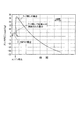
ここで、本実施形態(1)のリーク診断について詳しく説明する。エンジン停止後(IGスイッチ23のOFF後)に、直ちにパージ制御弁16を閉弁し、且つ大気開閉弁14を閉弁してエバポ系を密閉する。エンジン停止直後は、排気系の温度が高いため、その熱で燃料タンク11内の燃料温度がエバポガスの発生しやすい温度に保たれてエバポガスの発生量が多くなるため、エンジン停止直後にエバポ系を密閉すれば、リーク無しの場合にエバポガスの発生によるタンク内圧上昇量(エバポ系の圧力上昇量)が大きくなる(図5の実線参照)。
【0024】
一方、リーク有りの場合は、エバポ系を密閉しても、エバポ系のリーク孔からエバポガスが大気中に漏れるため、エバポ系密閉後のタンク内圧(エバポ系の圧力)の上昇が少なくなり、比較的短い時間でタンク内圧が大気圧付近にまで低下する(図5の点線参照)。
【0025】
本実施形態(1)では、リーク診断期間中のタンク内圧の挙動を数値化するために、リーク診断期間中にタンク内圧センサ17によりゲージ圧(大気圧基準)で検出したタンク内圧(ゲージ圧=絶対圧−大気圧)を所定の演算周期で積算し、リーク診断終了時に、このタンク内圧積算値をリーク判定値と比較してリークの有無を診断する。
【0026】
ところで、エンジン停止中に、燃料タンク11の給油口キャップ(図示せず)を開放して燃料を補給することがあり、給油口キャップが開放されると、給油口キャップから燃料タンク11内(エバポ系内)に大気圧が一気に導入されるため、タンク内圧(エバポ系の圧力)が大気圧付近まで急低下する(図5の二点鎖線参照)。このため、エンジン停止中にタンク内圧(エバポ系の圧力)に基づいてリークの有無を診断する場合、給油口キャップが開放されると、エバポ系に大量のリークが発生している場合と同じように、タンク内圧が大気圧付近に低下するため、リーク有りと誤診断されてしまう可能性がある。
【0027】
通常、燃料タンク11の給油口キャップは、燃料を補給するときのみに開放され、給油口キャップを開放して燃料を補給すると、燃料タンク11内の燃料残量が増加する。そこで、本実施形態(1)では、エンジン始動時に、前回のエンジン停止時の燃料残量とエンジン始動時の燃料残量とを比較して、エンジン停止中に燃料タンク11の給油口キャップが開放されたか否かを判定する。そして、エンジン停止中に給油口キャップが開放されと判定された場合には、給油口キャップの開放による大気圧導入の影響を受けたエバポ系の圧力に基づいてリークの有無を診断した可能性があると判断して、リーク診断結果を無効にして、給油口キャップの開放によるリークの誤診断を防止する。
【0028】
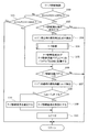
以上説明したリーク診断は、図2及び図3の各ルーチンに従って実行される。図2のリーク診断制御ベースルーチンは、制御回路21の電源供給中(メインリレー22のON中)に周期的に実行される。本ルーチンが起動されると、まず、ステップ100で、IGスイッチ23がONからOFFに切り換えられた直後であるか否か(つまりエンジン停止直後であるか否か)を判定し、IGスイッチ23がOFFされた直後であれば、ステップ102に進み、リーク診断実行条件が成立しているか否かを判定する。このリーク診断実行条件としては、例えば、燃料温度センサ26で検出した燃料温度がエバポガスの発生しやすい所定温度以上であることであり、燃料温度が所定温度以上であれば、リーク診断実行条件が成立する。
【0029】
尚、このリーク診断実行条件の判定は、燃料温度の代わりに、燃料温度に相関するパラメータ、例えば、エンジン停止前の走行履歴(走行時間、走行距離)、エンジン運転状態(冷却水温等)を用いても良い。例えば、走行時間が所定時間以上、又は走行距離が所定値以上であるときに、リーク診断実行条件が成立するようにしても良い。
【0030】
上記ステップ102で、燃料温度が所定温度未満で、リーク診断実行条件が成立しないと判定されれば、以降の処理を行うことなく、本ルーチンを終了する。一方、燃料温度が所定温度以上で、リーク診断実行条件が成立していると判定されれば、ステップ103に進み、IGスイッチ23のOFFによって燃料レベルセンサ18への供給電圧が正常動作電圧以下に低下する前に、燃料レベルセンサ18の出力信号を読み込んで、エンジン停止時の燃料タンク11内の燃料残量Loff を検出する。この後、ステップ104に進み、後述する図3のリーク診断ルーチンを実行することで、エンジン停止中にエバポ系のリーク診断を実施して、暫定的にリーク無し(正常)かリーク有り(異常)かを判定する。
【0031】
その後、ステップ105に進み、後述する図4のメインリレー制御ルーチンによるリーク診断終了に伴うメインリレー22のOFFによって制御回路21への供給電圧が正常動作電圧以下に低下する前に、リーク診断結果(正常コード又は異常コード)を制御回路21のバックアップRAM(図示せず)に記憶すると共に、リーク診断実施フラグLCをリーク診断の実施済みを意味する「1」にセットして制御回路21のバックアップRAMに記憶する。これにより、制御回路21への電源供給遮断後も、リーク診断結果及びリーク診断実施フラグLC=1を記憶し続ける。
【0032】
その後、IGスイッチ23がOFFからONに切り換えられてエンジンが始動されたときに、本ルーチンが起動されると、ステップ100で「No」、ステップ101で「Yes」と判定されてステップ106に進み、リーク診断実施フラグLCがリーク診断の実施済みを意味する「1」にセットされているか否かを判定する。
【0033】
このステップ106で、リーク診断実施フラグLC=0(リーク診断の未実施)と判定されれば、以降の処理を行うことなく、本ルーチンを終了する。一方、リーク診断実施フラグLC=1(リーク診断の実施済み)と判定されれば、ステップ107に進み、その時点の燃料レベルセンサ18の出力信号を読み込んで、エンジン始動時の燃料タンク11内の燃料残量Lonを検出する。この後、ステップ108に進み、エンジン始動時の燃料残量Lonと前回のエンジン停止時の燃料残量Loff との差(エンジン停止中の燃料残量の増加量)が燃料レベルセンサ18の検出誤差よりも少し大きい所定量Kよりも大きいか否かによって、エンジン停止中に燃料が補給されたか否か、つまり、エンジン停止中に燃料タンク11の給油口キャップが開放されたか否かを判定する。このステップ108の処理が特許請求の範囲でいう給油口開放判定手段としての役割を果たす。
【0034】
このステップ108で「Yes」と判定された場合(エンジン停止中に給油口キャップが開放されたと判定された場合)には、給油口キャップの開放による大気圧導入の影響を受けたエバポ系の圧力に基づいてリークの有無を診断した可能性があると判断して、ステップ109に進み、バックアップRAMに記憶されている暫定的なリーク診断結果をクリアしてリーク診断結果を無効にする。このステップ109の処理が特許請求の範囲でいうリーク診断結果無効手段としての役割を果たす。
【0035】
これに対して、上記ステップ108で「No」と判定された場合(エンジン停止中に給油口キャップが開放されなかったと判定された場合)には、ステップ110に進み、バックアップRAMに記憶されている暫定的なリーク診断結果をそのまま最終的なリーク診断結果として確定し、リーク有り(異常)の場合には、警告ランプ27を点灯して運転者に警告する。
その後、ステップ109又は110からステップ111に進み、リーク診断実施フラグLCを「0」にリセットして、本ルーチンを終了する。
【0036】
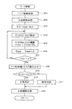
一方、図2のステップ104で実行される図3のリーク診断ルーチンは、次のようにしてエンジン停止後(イグニッションスイッチ23のOFF後)にエバポ系のリーク診断を実行することで、特許請求の範囲でいうリーク診断手段としての役割を果たす。本ルーチンが起動されると、まず、ステップ201で、パージ制御弁16を閉弁し、次のステップ202で、大気開閉弁14を閉弁してエバポ系を密閉する。
【0037】
この後、ステップ203に進み、リーク診断開始後(エバポ系の密閉後)の経過時間を計測するタイマTimerをリセットする。この後、ステップ204に進み、タンク内圧センサ17の出力信号を読み込んで今回のタンク内圧Pa を検出し、次のステップ205で、前回までのタンク内圧積算値Ptotal に今回のタンク内圧Pa を加算してタンク内圧積算値Ptotal を更新する。この際、タンク内圧Pa は、大気圧を基準にして検出したゲージ圧(=絶対圧−大気圧)が用いられる。この後、ステップ206に進み、前回のタイマTimerの値に演算周期Aを加算して、タイマTimerのカウント値を更新する。
【0038】
そして、次のステップ207で、タイマTimerの値(リーク診断開始後の経過時間)が所定値αを越えたか否かを判定する。この所定値αは、演算処理の簡略化のために固定値(例えば5min)としても良いが、エンジン停止前の走行履歴(走行時間、走行距離)、エンジン運転状態(冷却水温等)に応じて補正するようにしても良い。
【0039】
タイマTimerの値が所定値αを越えていなければ、ステップ204に戻る。これにより、タイマTimerの値が所定値αを越えるまで、所定の演算周期Aでタンク内圧Pa を積算してタンク内圧積算値Ptotal を更新する処理を繰り返す。
【0040】
その後、タイマTimerの値が所定値αを越えた時点で、ステップ208に進み、エンジン停止時の燃料残量Loff に応じたリーク判定値f(L) を、燃料残量Loff をパラメータとするリーク判定値マップから読み込む(又は数式により算出する)。この後、ステップ209に進み、タンク内圧積算値Ptotal をリーク判定値f(L) と比較し、タンク内圧積算値Ptotal がリーク判定値f(L) よりも大きければ、ステップ210に進み、暫定的にリーク無し(正常)と判定し、次のステップ212で、大気開閉弁14を開弁してリーク診断を終了する。
【0041】
これに対し、上記ステップ209で、タンク内圧積算値Ptotal がリーク判定値f(L) 以下と判定されれば、ステップ211に進み、暫定的にリーク有り(異常)と判定し、次のステップ212で、大気開閉弁14を開弁してリーク診断を終了する。
【0042】
また、図4のメインリレー制御ルーチンは、所定時間毎に実行され、次のようにしてメインリレー22のON/OFFを制御する。本ルーチンが起動されると、まずステップ301で、IGスイッチ23がONされているか否か、つまりエンジン運転中であるか否かを判定し、IGスイッチ23がON状態(エンジン運転中)であれば、ステップ305に進み、メインリレー22をON状態に維持して、制御回路21、大気開閉弁14、パージ制御弁16及びタンク内圧センサ17に電源電圧を供給する。
【0043】
その後、IGスイッチ23がONからOFFに切り換えられた時点で、ステップ301で「No」と判定されてステップ302に進み、前記図3のリーク診断ルーチンによってリーク診断を実行している途中であるか否かを判定し、リーク診断を実行していなければ、ステップ304に進み、メインリレー22をOFFして、制御回路21、大気開閉弁14、パージ制御弁16及びタンク内圧センサ17への電源供給を遮断する。
【0044】
これに対し、上記ステップ302で、リーク診断実行中であると判定された場合は、ステップ303に進み、電源電圧がエンジン始動性を確保できる所定電圧よりも高いか否かを判定し、電源電圧が所定電圧以下であれば、ステップ304に進み、リーク診断の途中であっても、メインリレー22をOFFして、制御回路21、大気開閉弁14等への電源供給を遮断してリーク診断を中止し、バッテリの消耗を防ぐ。
【0045】
一方、電源電圧が所定電圧よりも高ければ、ステップ305に進み、IGスイッチ23のOFF後(エンジン停止後)であっても、メインリレー22をON状態に維持して、リーク診断の継続に必要な部品(制御回路21、大気開閉弁14等)への電源供給を継続する。そして、このリーク診断が終了した時点で、ステップ302で「No」と判定されて、ステップ304に進み、メインリレー22をOFFして、制御回路21、大気開閉弁14等への電源供給を遮断する。
【0046】
以上説明した本実施形態(1)では、エンジン停止後に、タンク内圧(エバポ系の圧力)に基づいてエバポ系のリークの有無を診断し、次のエンジン始動時に燃料タンク11の給油口キャップがエンジン停止中に開放されたか否かを判定して、エンジン停止中に給油口キャップが開放されたと判定された場合には、給油口キャップの開放による大気圧導入の影響を受けたタンク内圧に基づいてリークの有無を診断した可能性があると判断して、リーク診断結果を無効にする。これにより、リークが無いにも拘らず、給油口キャップの開放によってリーク有りと誤診断してしまうことを未然に防止することができ、エンジン停止中のリーク診断の信頼性を向上させることができる。
【0047】
また、本実施形態では、エンジン始動時に、前回のエンジン停止時の燃料残量Loff とエンジン始動時の燃料残量Lonとを比較して、エンジン停止中に燃料タンク11の給油口キャップが開放されたか否かを判定するようにしたので、エンジン停止中に、燃料レベルセンサ18で燃料残量を監視する必要がなく、燃料レベルセンサ18への電源供給を停止することができて、エンジン停止中のバッテリ消費電力を少なくすることができる。しかも、給油口キャップの開閉を検出するスイッチ(又はセンサ)が不要であるため、製造コスト低減の要求も満たすことができる。
【0048】
尚、本実施形態(1)では、エンジン始動時に、給油口キャップがエンジン停止中に開放されたと判定された場合、リーク診断結果の正常、異常を問わず、そのリーク診断結果を全て無効にするようにしたが、異常(リーク有り)の判定結果のみを無効とし、正常(リーク無し)の判定結果はそのまま最終的な判定結果として確定するようにしても良い。
【0049】
[実施形態(2)]
ところで、エンジン停止中に給油口キャップが開放された場合のうち、リーク診断開始前やリーク診断中に給油口キャップが開放された場合は、給油口キャップの開放による大気圧導入の影響を受けたエバポ系の圧力に基づいてリーク診断してしまうため、リークの有無を誤診断する可能性が高い。しかし、エンジン停止中に給油口キャップが開放された場合でも、リーク診断終了後に給油口キャップが開放された場合は、給油口キャップの開放による大気圧導入の前にリーク診断を終了しているので、リーク診断結果が給油口キャップの開放の影響を受けることはない。
【0050】
このような事情を考慮して、図6及び図7に示す本発明の実施形態(2)では、エンジン停止中に燃料タンク11の給油口キャップが開放されたか否かを判定し、リーク診断が終了する前に給油口キャップが開放されたと判定されれば、その時点で、リーク診断を中止するようにしている。
【0051】
以下、本実施形態(2)で用いる図6に示すリーク診断制御ベースルーチンと図7に示すメインリレー制御ルーチンの処理内容を説明する。
図6のリーク診断制御ベースルーチンでは、IGスイッチ23がOFFされた直後(エンジン停止直後)に、リーク診断実行条件が成立しているか否かを判定し(ステップ401、402)、リーク診断実行条件が成立していれば、前記実施形態(1)で説明した図3のリーク診断ルーチンを実行することで、エバポ系のリーク診断を実施して、エバポ系のリークの有無を判定し(ステップ403)、そのリーク診断結果(正常コード又は異常コード)を制御回路21のバックアップRAMに記憶する(ステップ404)。
【0052】
一方、図7のメインリレー制御ルーチンは、前記実施形態(1)で説明した図4のステップ301とステップ302の処理の間にステップ301aの処理を追加したものであり、それ以外の各ステップの処理は前記図4のメインリレー制御ルーチンと同じである。
【0053】
図7のメインリレー制御ルーチンでは、IGスイッチ23がOFFされてエンジンが停止された後(ステップ301)、ステップ301aに進み、燃料タンク11の給油口キャップが開放されたか否かを、タンク内圧が急変したか否かによって判定する。燃料タンク11の給油口キャップが開放されると、給油口キャップから燃料タンク11内(エバポ系内)に大気圧が一気に導入されて、タンク内圧(エバポ系の圧力)が急変する。従って、タンク内圧が急変したときには、燃料タンク11の給油口キャップが開放されたと判定する。
【0054】
上記ステップ301aで、燃料タンク11の給油口キャップが開放されたと判定されたときは、リークの有無を誤診断する可能があると判断して、ステップ304に進み、リーク診断中であっても、メインリレー22をOFFして、制御回路21、大気開閉弁14等への電源供給を遮断してリーク診断を中止する。
【0055】
以上説明した本実施形態(2)では、リーク診断終了前に給油口キャップが開放されたときには、リークの有無を誤診断する可能があると判断して、リーク診断を中止することができる。一方、リーク診断終了後に給油口キャップが開放されたときは、それ以前に行われたリーク診断の結果に給油口キャップの開放が何ら影響を及ぼさないため、そのリーク診断結果をそのまま採用する。これにより、給油口キャップの開放によるリークの誤診断を防止しながら、エンジン停止中に給油口キャップが開放されたときに、常にリーク診断結果を無効にしてしまう場合に比べてリーク診断の頻度を多くすることができる。
【0056】
また、本実施形態(2)では、エンジン停止中にタンク内圧が急変したときに、給油口キャップが開放されたと判定するようにしたが、エンジン停止中(リーク診断中)に、電源電圧がメインリレー22を介して燃料レベルセンサ18に供給される構成とし、エンジン停止中に燃料レベルセンサ18で検出した燃料残量が検出誤差を越えて増加したときに、給油口キャップが開放されたと判定するようにしても良い。
【0057】
或は、給油口キャップの開閉を検出するスイッチ又はセンサを設けるようにしても良い。このようにすれば、タンク内圧が大気圧付近のときに給油口キャップが開放された場合や、給油量(燃料残量の増加量)が少ない場合でも、給油口キャップの開閉を正確且つ即座に検出することができる。
【0058】
また、車両の運転席に給油口キャップの開放を遠隔操作する操作スイッチが装備されている場合は、この操作スイッチの操作信号によって給油口キャップの開放を検出するようにしても良い。
【0059】
[実施形態(3)]
次に、図8乃至図10を用いて本発明の実施形態(3)を説明する。
図10のタイムチャートに二点鎖線で示すように、エンジン停止後のリーク診断期間中に燃料タンク11の給油口キャップが開放されると、タンク内圧は、大気圧付近まで急低下した後、大気圧に維持され、その後、給油口に給油ノズルが差し込まれて給油が開始されると、タンク内圧がゆっくりと上昇する。
【0060】
そこで、本実施形態(3)では、エンジン停止後のリーク診断期間中に、所定の演算周期でタンク内圧変化率ΔPa (ΔPa =今回のタンク内圧Pa −前回のタンク内圧Pa )を算出し、▲1▼このタンク内圧変化率ΔPa が所定値β(<0)よりも小さいとき(つまり、タンク内圧が急低下したとき)、又は、▲2▼エンジン停止後にタンク内圧が大気圧状態になっている時間tが所定時間γ以上継続した後、タンク内圧変化率ΔPa が0以上になるとき(つまり、タンク内圧が変化しない状態が所定時間γ以上継続した後、タンク内圧が通常よりもゆっくりと上昇するとき)には、燃料タンク11の給油口キャップが開放されていると判定してリーク診断を中止する。
【0061】
以下、本実施形態(3)で実行する図8及び図9に示すリーク診断ルーチンの処理内容を説明する。エンジン停止後(イグニッションスイッチ23のオフ後)に、前記実施形態(1)と同様のリーク診断実行条件が成立すると(ステップ501〜502)、ステップ503に進み、パージ制御弁16を閉弁し、次のステップ504で、燃料残量Lを検出すると共にタイマTimer1 をリセットし、次のステップ505で、大気開閉弁14を閉弁してエバポ系を密閉してリーク診断を開始する。
【0062】
この後、ステップ506に進み、タンク内圧Pa を検出した後、ステップ507に進み、タンク内圧Pa が負圧(Pa <0)であるか否かを判定し、負圧であれば、ステップ506に戻り、再びタンク内圧Pa を検出する。
【0063】
その後、タンク内圧Pa が大気圧又は正圧(Pa ≧0)になった時点(エバポ系の密閉によってタンク内圧Pa が上昇し始めた時点)で、ステップ508に進み、燃料タンク11の給油口キャップが開放されたか否かを判定するために、タンク内圧変化率ΔPa (ΔPa =今回のタンク内圧Pa−前回のタンク内圧Pa )を算出し、▲1▼このタンク内圧変化率ΔPa が所定値β(<0)よりも小さいか否か、又は、▲2▼エンジン停止後にタンク内圧が大気圧状態になっている時間tが所定時間γ以上継続した後、タンク内圧変化率ΔPa が0以上になったか否かを判定する。ここで、所定値βは、通常のリーク診断期間中(図10の実線で示す場合)に発生するタンク内圧低下率よりも小さい値に設定され、また、所定時間γは、通常のリーク診断期間中の大気圧状態の継続時間よりも長い時間に設定されている。
【0064】
このステップ508で、▲1▼タンク内圧変化率ΔPa が所定値βよりも小さいとき(つまり、タンク内圧Paが通常よりも急低下したとき)、又は、▲2▼タンク内圧Paが大気圧状態になっている時間tが所定時間γ以上継続した後、タンク内圧変化率ΔPa が0以上になったとき(つまり、タンク内圧Paが変化しない状態が所定時間γ以上継続した後、タンク内圧Paが通常よりもゆっくりと上昇するとき)には、燃料タンク11の給油口キャップが開放されて給油されていると判定する(給油フラグをONにセットする)。このステップ508の処理が特許請求の範囲でいう給油口開放判定手段としての役割を果たす。
上記ステップ508で、燃料タンク11の給油口キャップが開放されたと判定されれば、リーク診断処理を中止して、本ルーチンを終了する。
【0065】
一方、燃料タンク11の給油口キャップが開放されていないと判定されれば、タイマTimer1 の値が所定値αを越えるまで、所定の演算周期Aでタンク内圧Pa を積算してタンク内圧積算値Ptotal を更新する処理を繰り返す(ステップ509〜511)。
【0066】
その後、タイマTimer1 の値が所定値αを越えた時点で、図9のステップ512に進み、現在の燃料残量Lに応じたリーク判定値f(L) を読み込み、次のステップ513で、タンク内圧積算値Ptotal をリーク判定値f(L) と比較し、タンク内圧積算値Ptotal がリーク判定値f(L) よりも大きければ、ステップ514に進み、リーク無し(正常)と判定し、次のステップ517で、大気開閉弁14を開弁してリーク診断を終了する。
【0067】
これに対し、上記ステップ513で、タンク内圧積算値Ptotal がリーク判定値f(L) 以下と判定されれば、ステップ515に進み、リーク有り(異常)と判定して、次のステップ516で、警告ランプ27を点灯して運転者に警告すると共に、異常コードを制御回路21のバックアップRAM(図示せず)に記憶し、次のステップ517で、大気開閉弁14を開弁してリーク診断を終了する。
【0068】
以上説明した本実施形態(3)のようにしても、給油口キャップの開放によるリークの誤診断を防止しながら、エンジン停止中に給油口キャップが開放されたときに、常にリーク診断結果を無効にしてしまう場合に比べてリーク診断の頻度を多くすることができる。
【0069】
尚、上記各実施形態(2),(3)では、リーク診断終了前に給油口キャップが開放されたときに、直ちにリーク診断を中止するようにしたが、リーク診断の終了後にそのリーク診断結果を無効にするようにしても良い。この場合、リーク診断結果の正常、異常を問わず、そのリーク診断結果を全て無効にするようにしても良いが、異常(リーク有り)の判定結果のみを無効とし、正常(リーク無し)の判定結果はそのまま最終的な判定結果として確定するようにしても良い。
【0070】
また、上記各実施形態(1)〜(3)では、リーク診断期間中にタンク内圧を所定の演算周期で積算して求めたタンク内圧積算値をリーク判定値と比較してリークの有無を診断するようにしたが、リーク診断の方法は、適宜変更しても良いことは言うまでもない。
【0071】
例えば、リーク診断期間中にタンク内圧の最大値を検出し、このタンク内圧最大値をリーク判定値と比較してリークの有無を診断するようにしても良い。
或は、リーク診断開始(エバポ系の密閉)から所定時間経過後に検出したタンク内圧をリーク判定値と比較してリークの有無を診断するようにしても良い。
【0072】
或は、リーク診断開始後にタンク内圧の変化を監視し、タンク内圧の上昇率が所定値以下(例えばほぼ0)になるまでの時間を測定し、その時間がリーク判定値よりも短いか否かで、リークの有無を判定するようにしても良い。
【0073】
或は、リーク診断開始から所定時間経過する前にタンク内圧が所定圧以下(例えば大気圧付近)に低下したか否かで、リークの有無を診断するようにしても良い。
【0074】
尚、前記実施形態(1)〜(3)では、エンジン停止直後にエバポ系を密閉して直ちにタンク内圧の検出(リーク診断)を開始するようにしたが、エバポ系の密閉後、リーク有りとリーク無しの場合のタンク内圧の違いが明瞭に現れるまでの暫くの時間が経過してからタンク内圧の検出(リーク診断)を開始するようにしても良い。
【図面の簡単な説明】
【図1】本発明の実施形態(1)におけるエバポガスパージシステムの構成を示す図
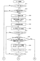
【図2】実施形態(1)のリーク診断制御ベースルーチンの処理の流れを示すフローチャート
【図3】実施形態(1)のリーク診断ルーチンの処理の流れを示すフローチャート
【図4】実施形態(1)のメインリレー制御ルーチンの処理の流れを示すフローチャート
【図5】エンジン停止後のタンク内圧の挙動を示すタイムチャート
【図6】実施形態(2)のリーク診断制御ベースルーチンの処理の流れを示すフローチャート
【図7】実施形態(2)のメインリレー制御ルーチンの処理の流れを示すフローチャート
【図8】実施形態(3)のリーク診断ルーチンの処理の流れを示すフローチャート(その1)
【図9】実施形態(3)のリーク診断ルーチンの処理の流れを示すフローチャート(その2)
【図10】実施形態(3)の給油口開放判定方法を説明するためのタイムチャート
【符号の説明】
11…燃料タンク、12…エバポ通路、13…キャニスタ、14…大気開閉弁、15…パージ通路、16…パージ制御弁、17…タンク内圧センサ(内圧検出手段)、18…燃料レベルセンサ(燃料残量検出手段)、19…水温センサ、20…吸気温センサ、21…制御回路(リーク診断手段,給油口開放判定手段,リーク診断結果無効手段,リーク診断中止手段)、22…メインリレー、23…イグニッションスイッチ、24…バックアップ電源、25…ソークタイマ、26…燃料温度センサ、27…警告ランプ。[0001]
BACKGROUND OF THE INVENTION
The present invention relates to a leak diagnosis apparatus for an evaporative gas purge system that performs a leak diagnosis of an evaporative gas purge system that purges (releases) evaporative gas (fuel evaporative gas) generated by evaporation of fuel in a fuel tank into an intake system of an internal combustion engine. It is.
[0002]
[Prior art]
Conventionally, in an evaporative gas purge system, in order to prevent the evaporative gas generated from the fuel tank from leaking into the atmosphere, the evaporative gas in the fuel tank is adsorbed in the canister through the evaporative passage and is adsorbed in the canister. The purge gas is purged from the canister to the intake system by providing a purge control valve in the middle of the purge passage for purging the evaporated gas to the intake system of the internal combustion engine and controlling the opening and closing of the purge control valve according to the operating state of the internal combustion engine The purge flow rate is controlled. In order to prevent the state in which the evaporative gas leaks from the evaporative gas purge system from being left in the atmosphere for a long period of time, it is necessary to detect the evaporative gas leak at an early stage.
[0003]
Therefore, a pressure sensor for detecting the pressure in the fuel tank (hereinafter referred to as “tank pressure”) was provided, and the purge control valve was opened during operation of the internal combustion engine to introduce negative pressure into the fuel tank from the intake system. After that, with the purge control valve closed and the evaporation system from the purge control valve to the fuel tank sealed, the amount of change in the tank internal pressure is measured, and the amount of change in the tank internal pressure is compared with the leak judgment value. Thus, there is one that diagnoses the presence or absence of an evaporative leak. In this case, if there is no leak in the evaporation system, the amount of change in the tank internal pressure will be a value corresponding to the amount of evaporation gas generated and will be smaller than the leak judgment value, but if there is a leak, the amount of change in the tank internal pressure will leak. It becomes larger by the amount and exceeds the leak judgment value.
[0004]
In general, leak diagnosis is performed under stable operating conditions such as idling and low-speed driving so as not to be affected by changes in the operating conditions of the internal combustion engine. If the amount measurement time is set to a long time, even if the leak diagnosis is started during the operation of the internal combustion engine, the operation conditions of the internal combustion engine change or the operation of the internal combustion engine is stopped during the leak diagnosis. As a result, the number of times the leak diagnosis is stopped increases significantly, and the number of times the leak diagnosis is performed to the end during the operation of the internal combustion engine is extremely reduced.
[0005]
Therefore, as shown in US Pat. No. 5,263,462, after the operation of the internal combustion engine is stopped, it is proposed to detect the pressure of the evaporation system (pressure in the tank) and diagnose the presence of the leakage of the evaporation system based on the pressure. Has been.
[0006]
[Problems to be solved by the invention]
However, after the operation of the internal combustion engine is stopped, the fuel tank cap may be opened to replenish the fuel, and when the fuel filler is opened, atmospheric pressure is introduced into the evaporation system from the fuel filler. . For this reason, in a system that diagnoses the presence or absence of a leak based on the pressure of the evaporation system after the operation of the internal combustion engine is stopped, when the fuel filler cap is opened, as in the case where a large amount of leakage occurs in the evaporation system, Since the evaporation system pressure changes to near atmospheric pressure, there is a possibility that it is erroneously diagnosed that there is a leak.
[0007]
The present invention has been made in view of such circumstances. Therefore, the object of the present invention is to prevent misdiagnosis of leaks due to opening of the filler cap, and reliability of leak diagnosis when the internal combustion engine is stopped. It is an object of the present invention to provide a leak diagnosis apparatus for an evaporation gas purge system that can improve the above.
[0008]
[Means for Solving the Problems]
In order to achieve the above object, the leak diagnosis apparatus for an evaporative gas purge system according to
[0009]
In other words, when it is determined that the fuel tank cap has been opened while the internal combustion engine was stopped before starting the internal combustion engine, the pressure of the evaporation system affected by the introduction of atmospheric pressure due to the opening of the filler cap Based on this, it is determined that there is a possibility of diagnosing the presence or absence of a leak, and the leak diagnosis result is invalidated. As a result, it is possible to prevent erroneous diagnosis that there is a leak due to the opening of the filler cap, and it is possible to improve the reliability of the leak diagnosis while the operation of the internal combustion engine is stopped.
[0011]
By the way, among the cases where the filler cap is opened while the internal combustion engine is stopped, if the filler cap is opened before the start of the leak diagnosis or during the leak diagnosis, the influence of the introduction of atmospheric pressure due to the opening of the filler cap is affected. Since leak diagnosis is performed based on the received pressure of the evaporation system, there is a high possibility of erroneous diagnosis that there is a leak. However, even if the filler cap is opened while the internal combustion engine is stopped, if the filler cap is opened after the leak diagnosis is completed, the leak diagnosis is completed before the introduction of atmospheric pressure by opening the filler cap. Therefore, the leak diagnosis result is not affected by the opening of the filler cap.
[0012]
In view of these circumstances, the
[0013]
In this case, the claim 3 As described above, it may be determined that the fuel filler cap is opened when the pressure detected by the internal pressure detecting means suddenly changes in the atmospheric pressure direction while the operation of the internal combustion engine is stopped. That is, when the fuel filler cap is opened, atmospheric pressure is introduced from the fuel filler into the evaporation system at a stretch, so the pressure in the evaporation system changes suddenly in the atmospheric pressure direction. Therefore, when the evaporation system pressure suddenly changes in the atmospheric pressure direction while the operation of the internal combustion engine is stopped, it can be determined that the filler cap is opened.
[0014]
Claims 4 As described above, a switch or sensor for detecting opening / closing of the filler cap may be provided as the filler opening determination means. In this way, even when the filler cap is opened when the evaporation system pressure is near atmospheric pressure, or when the amount of fuel (the increase in the amount of remaining fuel) is small, the filler cap can be opened and closed accurately. It can be detected immediately.
[0015]
Or
[0016]
DETAILED DESCRIPTION OF THE INVENTION
[Embodiment (1)]
Hereinafter, an embodiment (1) of the present invention will be described with reference to FIGS. First, the configuration of the evaporation gas purge system will be described with reference to FIG. A
[0017]
This atmospheric on-off
[0018]
On the other hand, a
[0019]
The
[0020]
The
[0021]
Outputs of these various sensors are input to the
[0022]
The
[0023]
Here, the leak diagnosis of the present embodiment (1) will be described in detail. Immediately after the engine is stopped (after the
[0024]
On the other hand, when there is a leak, even if the evaporation system is sealed, the evaporation gas leaks into the atmosphere from the evaporation system leak hole, so the increase in tank internal pressure (evaporation system pressure) after the evaporation system is sealed is reduced. In a short time, the tank internal pressure decreases to near atmospheric pressure (see the dotted line in FIG. 5).
[0025]
In this embodiment (1), in order to quantify the behavior of the tank internal pressure during the leak diagnosis period, the tank internal pressure (gauge pressure = gauge pressure) detected by the tank
[0026]
By the way, when the engine is stopped, the fuel filler cap (not shown) of the
[0027]
Usually, the fuel filler cap of the
[0028]
The leak diagnosis described above is executed according to the routines shown in FIGS. The leak diagnosis control base routine of FIG. 2 is periodically executed while the
[0029]
The leak diagnosis execution condition is determined using parameters correlated with the fuel temperature, for example, a travel history (travel time, travel distance) before the engine is stopped, and an engine operation state (cooling water temperature, etc.) instead of the fuel temperature. May be. For example, the leak diagnosis execution condition may be satisfied when the traveling time is a predetermined time or longer or the traveling distance is a predetermined value or longer.
[0030]
If it is determined in
[0031]
After that, the routine proceeds to step 105, where the leakage diagnosis result (before the supply voltage to the
[0032]
Thereafter, when this routine is started when the
[0033]
If it is determined in
[0034]
If it is determined as “Yes” in step 108 (when it is determined that the filler cap is opened while the engine is stopped), the pressure of the evaporation system affected by the introduction of atmospheric pressure due to the opening of the filler cap Based on the above, it is determined that there is a possibility that the presence or absence of a leak has been diagnosed, and the process proceeds to step 109 to clear the provisional leak diagnosis result stored in the backup RAM and invalidate the leak diagnosis result. The process of
[0035]
On the other hand, when it is determined “No” in step 108 (when it is determined that the filler cap is not opened while the engine is stopped), the process proceeds to step 110 and is stored in the backup RAM. The provisional leak diagnosis result is determined as it is as the final leak diagnosis result, and when there is a leak (abnormal), the warning
Thereafter, the process proceeds from
[0036]
On the other hand, the leak diagnosis routine of FIG. 3 executed in
[0037]
Thereafter, the process proceeds to step 203, and the timer Timer that measures the elapsed time after the start of the leak diagnosis (after the evaporation system is sealed) is reset. Thereafter, the process proceeds to step 204, where the output signal of the tank
[0038]
Then, in the
[0039]
If the value of the timer Timer does not exceed the predetermined value α, the process returns to step 204. Thus, the process of adding the tank internal pressure Pa and updating the tank internal pressure integrated value Ptotal is repeated at a predetermined calculation cycle A until the value of the timer Timer exceeds the predetermined value α.
[0040]
Thereafter, when the value of the timer Timer exceeds the predetermined value α, the routine proceeds to step 208, where the leak judgment value f (L) corresponding to the fuel remaining amount Loff at the time of engine stop is used, and the fuel remaining amount Loff is used as a parameter. Read from the judgment value map (or calculate by mathematical formula). Thereafter, the process proceeds to step 209, where the tank internal pressure integrated value Ptotal is compared with the leak judgment value f (L). If the tank internal pressure integrated value Ptotal is larger than the leak judgment value f (L), the process proceeds to step 210, and provisional. In
[0041]
On the other hand, if it is determined in
[0042]
Further, the main relay control routine of FIG. 4 is executed every predetermined time, and controls ON / OFF of the
[0043]
Thereafter, when the
[0044]
On the other hand, if it is determined in
[0045]
On the other hand, if the power supply voltage is higher than the predetermined voltage, the process proceeds to step 305, and the
[0046]
In the present embodiment (1) described above, after the engine is stopped, the presence or absence of the leakage of the evaporation system is diagnosed based on the tank internal pressure (evaporation system pressure), and the fuel filler cap of the
[0047]
Further, in the present embodiment, when the engine is started, the fuel remaining amount Loff at the previous engine stop is compared with the fuel remaining amount Lon at the time of engine start, and the fuel filler cap of the
[0048]
In the present embodiment (1), when it is determined that the filler cap is opened while the engine is stopped at the time of engine start, the leak diagnosis result is invalidated regardless of whether the leak diagnosis result is normal or abnormal. However, only the determination result of abnormality (with leak) may be invalidated, and the determination result of normal (no leak) may be determined as it is as the final determination result.
[0049]
[Embodiment (2)]
By the way, among the cases where the filler cap was opened while the engine was stopped, when the filler cap was opened before the start of the leak diagnosis or during the leak diagnosis, it was affected by the introduction of atmospheric pressure due to the opening of the filler cap. Since the leak diagnosis is performed based on the pressure of the evaporation system, there is a high possibility of misdiagnosing the presence or absence of the leak. However, even if the filler cap is opened while the engine is stopped, if the filler cap is opened after the leak diagnosis is completed, the leak diagnosis is completed before the introduction of atmospheric pressure by opening the filler cap. The leak diagnosis result is not affected by the opening of the filler cap.
[0050]
In consideration of such circumstances, in the embodiment (2) of the present invention shown in FIGS. 6 and 7, it is determined whether or not the filler cap of the
[0051]
The processing contents of the leak diagnosis control base routine shown in FIG. 6 and the main relay control routine shown in FIG. 7 used in this embodiment (2) will be described below.
In the leak diagnosis control base routine of FIG. 6, immediately after the
[0052]
On the other hand, the main relay control routine of FIG. 7 is obtained by adding the processing of
[0053]
In the main relay control routine of FIG. 7, after the
[0054]
When it is determined in
[0055]
In this embodiment (2) described above, when the filler cap is opened before the end of the leak diagnosis, it is determined that there is a possibility of misdiagnosing the presence or absence of the leak, and the leak diagnosis can be stopped. On the other hand, when the filler cap is opened after the end of the leak diagnosis, since the opening of the filler cap has no influence on the result of the leak diagnosis performed before that, the leak diagnosis result is adopted as it is. As a result, the frequency of leak diagnosis can be reduced compared to the case where the leak diagnosis result is always invalidated when the filler cap is opened while the engine is stopped, while preventing leak diagnosis due to opening of the filler cap. Can do a lot.
[0056]
Further, in this embodiment (2), when the tank internal pressure suddenly changes while the engine is stopped, it is determined that the fuel filler cap is opened. The fuel supply is supplied to the
[0057]
Or you may make it provide the switch or sensor which detects opening and closing of a filler cap. In this way, even if the filler cap is opened when the tank internal pressure is close to atmospheric pressure, or even when the amount of fuel (the increase in the remaining amount of fuel) is small, the filler cap is opened and closed accurately and immediately. Can be detected.
[0058]
Further, when an operation switch for remotely operating the opening of the filler cap is provided in the driver's seat of the vehicle, the opening of the filler cap may be detected by an operation signal of the operation switch.
[0059]
[Embodiment (3)]
Next, Embodiment (3) of this invention is demonstrated using FIG. 8 thru | or FIG.
As indicated by the two-dot chain line in the time chart of FIG. 10, when the fuel filler cap of the
[0060]
Therefore, in this embodiment (3), the tank internal pressure change rate ΔPa (ΔPa = current tank internal pressure Pa−previous tank internal pressure Pa) is calculated at a predetermined calculation period during the leak diagnosis period after the engine is stopped. 1) When this tank internal pressure change rate ΔPa is smaller than a predetermined value β (<0) (that is, when the tank internal pressure suddenly decreases), or (2) The tank internal pressure is in the atmospheric pressure state after the engine is stopped. When the tank internal pressure change rate ΔPa becomes 0 or more after the time t continues for the predetermined time γ or more (that is, after the state where the tank internal pressure does not change continues for the predetermined time γ or more, the tank internal pressure increases more slowly than usual). Time), it is determined that the fuel filler cap of the
[0061]
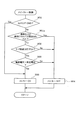
The processing contents of the leak diagnosis routine shown in FIGS. 8 and 9 executed in the present embodiment (3) will be described below. After the engine is stopped (after the
[0062]
Thereafter, the process proceeds to step 506, and after detecting the tank internal pressure Pa, the process proceeds to step 507, where it is determined whether the tank internal pressure Pa is a negative pressure (Pa <0). Then, the tank internal pressure Pa is detected again.
[0063]
After that, when the tank internal pressure Pa becomes atmospheric pressure or positive pressure (Pa ≧ 0) (when the tank internal pressure Pa starts to increase due to the sealing of the evaporation system), the routine proceeds to step 508 and the fuel filler cap of the
[0064]
In this
If it is determined in
[0065]
On the other hand, if it is determined that the fuel filler cap of the
[0066]
Thereafter, when the value of the timer Timer1 exceeds the predetermined value α, the routine proceeds to step 512 in FIG. 9, where the leak judgment value f (L) corresponding to the current fuel remaining amount L is read, and in the
[0067]
On the other hand, if it is determined in
[0068]
Even in the present embodiment (3) described above, the leakage diagnosis result is always invalidated when the filler cap is opened while the engine is stopped, while preventing the erroneous diagnosis of the leak due to the opening of the filler cap. The frequency of leak diagnosis can be increased as compared with the case where the error is detected.
[0069]
In each of the above embodiments (2) and (3), the leak diagnosis is immediately stopped when the filler cap is opened before the leak diagnosis ends. However, the leak diagnosis result after the leak diagnosis ends. May be disabled. In this case, the leak diagnosis result may be invalidated regardless of whether the leak diagnosis result is normal or abnormal, but only the abnormality (leak) determination result is invalid and normal (no leak) is determined. The result may be determined as a final determination result as it is.
[0070]
In the above embodiments (1) to (3), the tank internal pressure integrated value obtained by integrating the tank internal pressure at a predetermined calculation period during the leak diagnosis period is compared with the leak determination value to diagnose the presence or absence of the leak. However, it goes without saying that the leak diagnosis method may be changed as appropriate.
[0071]
For example, the maximum value of the tank internal pressure may be detected during the leak diagnosis period, and the tank internal pressure maximum value may be compared with the leak determination value to diagnose the presence or absence of the leak.
Alternatively, the presence or absence of a leak may be diagnosed by comparing the tank internal pressure detected after a predetermined time has elapsed from the start of leak diagnosis (sealing of the evaporation system) with a leak determination value.
[0072]
Alternatively, the change in the tank internal pressure is monitored after the leak diagnosis is started, and the time until the rate of increase in the tank internal pressure becomes a predetermined value or less (for example, approximately 0) is measured. Thus, the presence or absence of a leak may be determined.
[0073]
Alternatively, the presence or absence of a leak may be diagnosed based on whether or not the tank internal pressure has dropped below a predetermined pressure (for example, near atmospheric pressure) before a predetermined time has elapsed since the start of the leak diagnosis.
[0074]
In the above-described embodiments (1) to (3), the evaporation system is sealed immediately after the engine is stopped and the detection of the tank internal pressure (leak diagnosis) is started immediately. However, after the evaporation system is sealed, there is a leak. Detection of tank internal pressure (leak diagnosis) may be started after a lapse of time until a difference in tank internal pressure in the case of no leak appears clearly.
[Brief description of the drawings]
FIG. 1 is a diagram showing a configuration of an evaporation gas purge system in an embodiment (1) of the present invention.
FIG. 2 is a flowchart showing a flow of processing of a leak diagnosis control base routine of the embodiment (1).
FIG. 3 is a flowchart showing a flow of processing of a leak diagnosis routine of the embodiment (1).
FIG. 4 is a flowchart showing a process flow of a main relay control routine of the embodiment (1).
FIG. 5 is a time chart showing the behavior of tank internal pressure after engine stop
FIG. 6 is a flowchart showing a flow of processing of a leak diagnosis control base routine of the embodiment (2).
FIG. 7 is a flowchart showing a process flow of a main relay control routine of the embodiment (2).
FIG. 8 is a flowchart (No. 1) showing a flow of processing of a leak diagnosis routine of the embodiment (3).
FIG. 9 is a flowchart (part 2) illustrating the flow of processing of a leak diagnosis routine according to the embodiment (3).
FIG. 10 is a time chart for explaining a method for determining whether a filler opening is open in the embodiment (3).
[Explanation of symbols]
DESCRIPTION OF
Claims (5)
前記燃料タンクを含むエバポ系の圧力を検出する内圧検出手段と、
内燃機関運転停止中に前記内圧検出手段で検出した圧力に基づいて前記エバポ系のリークの有無を診断するリーク診断手段と内燃機関運転停止中に前記燃料タンクの給油口キャップが開放されたか否かを判定する給油口開放判定手段と、
内燃機関始動時に前記給油口開放判定手段の判定結果に基づいて内燃機関運転停止中に前記給油口キャップが開放されたと判定された場合に当該内燃機関運転停止中に前記リーク診断手段で診断されたリーク診断結果を無効にするリーク診断結果無効手段とを備えていることを特徴とするエバポガスパージシステムのリーク診断装置。In an evaporation gas purge system for purging the evaporation gas generated by evaporation of fuel in the fuel tank to the intake system of the internal combustion engine,
An internal pressure detecting means for detecting the pressure of an evaporation system including the fuel tank;
Leak diagnostic means for diagnosing the presence or absence of leakage in the evaporation system based on the pressure detected by the internal pressure detecting means while the internal combustion engine is stopped, and whether the fuel filler cap of the fuel tank is opened while the internal combustion engine is stopped Refueling port opening determining means for determining
When it is determined that the fuel filler cap has been opened while the internal combustion engine is stopped based on the determination result of the fuel filler opening determination means when the internal combustion engine is started, a diagnosis is made by the leak diagnostic means while the internal combustion engine is stopped. A leak diagnosis apparatus for an evaporative gas purge system, comprising: a leak diagnosis result invalidating means for invalidating a leak diagnosis result.
前記燃料タンクを含むエバポ系の圧力を検出する内圧検出手段と、
内燃機関運転停止中に前記内圧検出手段で検出した圧力に基づいて前記エバポ系のリークの有無を診断するリーク診断手段と内燃機関運転停止中に前記燃料タンクの給油口キャップが開放されたか否かを判定する給油口開放判定手段と、
内燃機関運転停止時から前記リーク診断手段によるリーク診断が終了する前に前記給油口開放判定手段で前記給油口キャップが開放されたと判定された場合に当該リーク診断を中止する又は当該リーク診断結果を無効にするリーク診断中止手段とを備えていることを特徴とするエバポガスパージシステムのリーク診断装置。In an evaporation gas purge system for purging the evaporation gas generated by evaporation of fuel in the fuel tank to the intake system of the internal combustion engine,
An internal pressure detecting means for detecting the pressure of an evaporation system including the fuel tank;
Leak diagnostic means for diagnosing the presence or absence of leakage in the evaporation system based on the pressure detected by the internal pressure detecting means while the internal combustion engine is stopped, and whether the fuel filler cap of the fuel tank is opened while the internal combustion engine is stopped Refueling port opening determining means for determining
The said filler cap in the filler opening opening determining means to stop the leak diagnosis if it is determined to have been opened or the leak diagnosis before the leakage diagnosis by the leakage diagnosis means from when the internal combustion engine operation stop ends A leak diagnosis apparatus for an evaporative gas purge system, comprising: a leak diagnosis stop means for disabling.
前記給油口開放判定手段は、内燃機関運転停止中に前記燃料残量検出手段で検出した燃料残量が所定量以上増加したときに前記給油口キャップが開放されたと判定することを特徴とする請求項2に記載のエバポガスパージシステムのリーク診断装置。Fuel remaining amount detecting means for detecting the remaining amount of fuel in the fuel tank;
The fuel filler opening determining means determines that the fuel filler cap is opened when the fuel remaining amount detected by the fuel remaining amount detecting means increases by a predetermined amount or more while the operation of the internal combustion engine is stopped. Item 3. The leakage diagnosis device for an evaporation gas purge system according to Item 2 .
Priority Applications (4)
| Application Number | Priority Date | Filing Date | Title |
|---|---|---|---|
| JP2001320468A JP4026348B2 (en) | 2001-10-18 | 2001-10-18 | Evaporative gas purge system leak diagnosis device |
| DE10248470A DE10248470A1 (en) | 2001-10-18 | 2002-10-17 | Fuel vapor leak checking device for vehicles, has checking unit detecting change in fuel vapor pressure, comparing unit indicating leak in fuel vapor passage and canceling unit canceling filler cap open check error |
| US10/273,186 US6854452B2 (en) | 2001-10-18 | 2002-10-18 | Fuel vapor handling system |
| JP2007139175A JP2007211789A (en) | 2001-10-18 | 2007-05-25 | Leak diagnosis device for evaporated gas purge system |
Applications Claiming Priority (2)
| Application Number | Priority Date | Filing Date | Title |
|---|---|---|---|
| JP2001320468A JP4026348B2 (en) | 2001-10-18 | 2001-10-18 | Evaporative gas purge system leak diagnosis device |
| JP2007139175A JP2007211789A (en) | 2001-10-18 | 2007-05-25 | Leak diagnosis device for evaporated gas purge system |
Related Child Applications (1)
| Application Number | Title | Priority Date | Filing Date |
|---|---|---|---|
| JP2007139175A Division JP2007211789A (en) | 2001-10-18 | 2007-05-25 | Leak diagnosis device for evaporated gas purge system |
Publications (2)
| Publication Number | Publication Date |
|---|---|
| JP2003120437A JP2003120437A (en) | 2003-04-23 |
| JP4026348B2 true JP4026348B2 (en) | 2007-12-26 |
Family
ID=47108311
Family Applications (2)
| Application Number | Title | Priority Date | Filing Date |
|---|---|---|---|
| JP2001320468A Expired - Fee Related JP4026348B2 (en) | 2001-10-18 | 2001-10-18 | Evaporative gas purge system leak diagnosis device |
| JP2007139175A Pending JP2007211789A (en) | 2001-10-18 | 2007-05-25 | Leak diagnosis device for evaporated gas purge system |
Family Applications After (1)
| Application Number | Title | Priority Date | Filing Date |
|---|---|---|---|
| JP2007139175A Pending JP2007211789A (en) | 2001-10-18 | 2007-05-25 | Leak diagnosis device for evaporated gas purge system |
Country Status (3)
| Country | Link |
|---|---|
| US (1) | US6854452B2 (en) |
| JP (2) | JP4026348B2 (en) |
| DE (1) | DE10248470A1 (en) |
Families Citing this family (25)
| Publication number | Priority date | Publication date | Assignee | Title |
|---|---|---|---|---|
| KR100579233B1 (en) * | 2003-05-27 | 2006-05-11 | 현대자동차주식회사 | Leak monitoring apparatus of a engine in vehicle |
| JP4433174B2 (en) | 2004-05-21 | 2010-03-17 | スズキ株式会社 | Evaporative fuel control device for internal combustion engine |
| US7251997B1 (en) * | 2004-07-28 | 2007-08-07 | Kavlico Corporation | Fuel tank module control system |
| JP2007085230A (en) * | 2005-09-21 | 2007-04-05 | Nissan Motor Co Ltd | Oil filler port opening detector for vaporized fuel processing system |
| DE102005048348A1 (en) * | 2005-10-10 | 2007-04-12 | Robert Bosch Gmbh | Method and device for leak testing of a tank system, in particular of a motor vehicle |
| EP1946134B1 (en) | 2005-11-09 | 2010-02-17 | Toyota Jidosha Kabushiki Kaisha | Battery condition diagnosis apparatus |
| DE102005058298A1 (en) | 2005-12-07 | 2007-06-21 | Robert Bosch Gmbh | Method and device for detecting tank leaks |
| JP2009118697A (en) * | 2007-11-09 | 2009-05-28 | Panasonic Corp | Method of controlling charge/discharge by battery |
| US8096438B2 (en) | 2008-06-03 | 2012-01-17 | Briggs & Stratton Corporation | Fuel tank cap for a fuel tank |
| US9422895B2 (en) * | 2010-09-24 | 2016-08-23 | Karma Automotive Llc | System for evaporative and refueling emission control for a vehicle |
| US8915234B2 (en) | 2010-10-25 | 2014-12-23 | Briggs & Stratton Corporation | Fuel cap |
| US8935081B2 (en) * | 2012-01-13 | 2015-01-13 | GM Global Technology Operations LLC | Fuel system blockage detection and blockage location identification systems and methods |
| US9243591B2 (en) * | 2012-09-11 | 2016-01-26 | Ford Global Technologies, Llc | Fuel system diagnostics |
| US9038489B2 (en) | 2012-10-15 | 2015-05-26 | GM Global Technology Operations LLC | System and method for controlling a vacuum pump that is used to check for leaks in an evaporative emissions system |
| US9341147B2 (en) * | 2013-03-07 | 2016-05-17 | Ford Global Technologies, Llc | Engine-off refueling detection method |
| US9176022B2 (en) | 2013-03-15 | 2015-11-03 | GM Global Technology Operations LLC | System and method for diagnosing flow through a purge valve based on a fuel system pressure sensor |
| US9316558B2 (en) | 2013-06-04 | 2016-04-19 | GM Global Technology Operations LLC | System and method to diagnose fuel system pressure sensor |
| JP2015075031A (en) * | 2013-10-09 | 2015-04-20 | 愛三工業株式会社 | Failure detection system in evaporable fuel treatment apparatus |
| DE102015217613A1 (en) * | 2015-09-15 | 2017-03-16 | Kautex Textron Gmbh & Co. Kg | Operating fluid container system for motor vehicles with improved misfuelling protection |
| JP6335967B2 (en) * | 2016-05-12 | 2018-05-30 | 本田技研工業株式会社 | Control method for fuel cell vehicle |
| EP3300939B8 (en) * | 2016-09-20 | 2019-09-11 | Plastic Omnium Advanced Innovation and Research | Method for controlling a pressure inside a fuel tank system |
| JP6972618B2 (en) * | 2017-03-31 | 2021-11-24 | ブラザー工業株式会社 | Image recording device |
| CN109630267B (en) * | 2018-11-16 | 2021-04-06 | 中国第一汽车股份有限公司 | Gasoline engine vehicle refueling state detection method |
| JP7417480B2 (en) * | 2020-06-22 | 2024-01-18 | 日立Astemo株式会社 | Vehicle electronic control unit |
| US11927153B2 (en) | 2021-10-14 | 2024-03-12 | Toyota Jidosha Kabushiki Kaisha | Diagnostic system for evaporated fuel treatment system |
Family Cites Families (8)
| Publication number | Priority date | Publication date | Assignee | Title |
|---|---|---|---|---|
| US5263462A (en) * | 1992-10-29 | 1993-11-23 | General Motors Corporation | System and method for detecting leaks in a vapor handling system |
| JP3277774B2 (en) * | 1995-11-14 | 2002-04-22 | 日産自動車株式会社 | Fault diagnosis device for evaporative fuel evaporation prevention device of internal combustion engine and fuel refueling detection device |
| JP3316376B2 (en) * | 1996-05-07 | 2002-08-19 | 三菱電機株式会社 | Abnormality detection device for fuel evaporation prevention device |
| US6283097B1 (en) * | 1997-08-25 | 2001-09-04 | John E. Cook | Automotive evaporative emission leak detection system |
| US6192742B1 (en) * | 1997-11-17 | 2001-02-27 | Denso Corporation | More reliable leakage diagnosis for evaporated gas purge system |
| US6119663A (en) * | 1998-03-31 | 2000-09-19 | Unisia Jecs Corporation | Method and apparatus for diagnosing leakage of fuel vapor treatment unit |
| JP3412678B2 (en) | 1998-05-15 | 2003-06-03 | 株式会社日立ユニシアオートモティブ | Leak diagnosis device for evaporative fuel treatment equipment |
| JP3621297B2 (en) * | 1999-06-30 | 2005-02-16 | 株式会社日立ユニシアオートモティブ | Failure diagnosis device for evaporative fuel treatment equipment |
-
2001
- 2001-10-18 JP JP2001320468A patent/JP4026348B2/en not_active Expired - Fee Related
-
2002
- 2002-10-17 DE DE10248470A patent/DE10248470A1/en not_active Ceased
- 2002-10-18 US US10/273,186 patent/US6854452B2/en not_active Expired - Lifetime
-
2007
- 2007-05-25 JP JP2007139175A patent/JP2007211789A/en active Pending
Also Published As
| Publication number | Publication date |
|---|---|
| JP2007211789A (en) | 2007-08-23 |
| DE10248470A1 (en) | 2003-05-22 |
| JP2003120437A (en) | 2003-04-23 |
| US20030075156A1 (en) | 2003-04-24 |
| US6854452B2 (en) | 2005-02-15 |
Similar Documents
| Publication | Publication Date | Title |
|---|---|---|
| JP4026348B2 (en) | Evaporative gas purge system leak diagnosis device | |
| JP2007211789A5 (en) | ||
| JP2688674B2 (en) | Failure detection device and failure compensation device for fuel tank internal pressure sensor | |
| JP4356991B2 (en) | Evaporative gas purge system leak diagnosis device | |
| JP2759908B2 (en) | Evaporative fuel processor for internal combustion engines | |
| JP2003074421A (en) | Leakage diagnosing device for evaporated gas purging system | |
| JP3621297B2 (en) | Failure diagnosis device for evaporative fuel treatment equipment | |
| US20050081612A1 (en) | Diagnosis apparatus for fuel vapor purge system and method thereof | |
| JP4497268B2 (en) | Fuel temperature estimation device and abnormality diagnosis device | |
| JP3664074B2 (en) | Abnormality diagnosis device for evaporative gas purge system | |
| JP2004300997A (en) | Leakage diagnostic device for evaporated gas purging system | |
| JP2009030606A (en) | Engine management system, monitoring method, and vehicle having engine management system | |
| JPH09137756A (en) | Failure diagnostic device for evaporated fuel transpiration preventive device of internal combustion engine and fuel supplying midst detection device | |
| JP2004293438A (en) | Leak diagnosing device of evaporation gas purging system | |
| JP2003056416A (en) | Leak diagnostic device for evaporated gas purge system | |
| JP4310836B2 (en) | Failure diagnosis device for evaporative fuel treatment system pressure detection means | |
| JP4431934B2 (en) | Evaporative gas purge system leak diagnosis device | |
| JP2007009849A (en) | Oil supply detection device of vehicle | |
| JP4356988B2 (en) | Evaporative gas purge system leak diagnosis device | |
| KR101558977B1 (en) | Apparatus for dignosing stuck of pressure switch for natural vaccum leak detection and method thereof | |
| JP4491769B2 (en) | Evaporative gas purge system leak diagnosis device | |
| KR100724262B1 (en) | Method for detecting stuck of fuel level sensor in car | |
| JP3449249B2 (en) | Abnormality diagnosis device for evaporative gas purge system | |
| JP4424074B2 (en) | Evaporative fuel processor failure detection device | |
| JP2004308612A (en) | Leak diagnostic device for evaporative emisssion purging system |
Legal Events
| Date | Code | Title | Description |
|---|---|---|---|
| A621 | Written request for application examination |
Free format text: JAPANESE INTERMEDIATE CODE: A621 Effective date: 20040121 |
|
| A131 | Notification of reasons for refusal |
Free format text: JAPANESE INTERMEDIATE CODE: A131 Effective date: 20061121 |
|
| A977 | Report on retrieval |
Free format text: JAPANESE INTERMEDIATE CODE: A971007 Effective date: 20061128 |
|
| A02 | Decision of refusal |
Free format text: JAPANESE INTERMEDIATE CODE: A02 Effective date: 20070330 |
|
| RD04 | Notification of resignation of power of attorney |
Free format text: JAPANESE INTERMEDIATE CODE: A7424 Effective date: 20070423 |
|
| A521 | Request for written amendment filed |
Free format text: JAPANESE INTERMEDIATE CODE: A523 Effective date: 20070525 |
|
| A911 | Transfer to examiner for re-examination before appeal (zenchi) |
Free format text: JAPANESE INTERMEDIATE CODE: A911 Effective date: 20070605 |
|
| TRDD | Decision of grant or rejection written | ||
| A01 | Written decision to grant a patent or to grant a registration (utility model) |
Free format text: JAPANESE INTERMEDIATE CODE: A01 Effective date: 20070918 |
|
| A61 | First payment of annual fees (during grant procedure) |
Free format text: JAPANESE INTERMEDIATE CODE: A61 Effective date: 20071001 |
|
| FPAY | Renewal fee payment (event date is renewal date of database) |
Free format text: PAYMENT UNTIL: 20101019 Year of fee payment: 3 |
|
| R150 | Certificate of patent or registration of utility model |
Free format text: JAPANESE INTERMEDIATE CODE: R150 |
|
| FPAY | Renewal fee payment (event date is renewal date of database) |
Free format text: PAYMENT UNTIL: 20101019 Year of fee payment: 3 |
|
| FPAY | Renewal fee payment (event date is renewal date of database) |
Free format text: PAYMENT UNTIL: 20111019 Year of fee payment: 4 |
|
| FPAY | Renewal fee payment (event date is renewal date of database) |
Free format text: PAYMENT UNTIL: 20121019 Year of fee payment: 5 |
|
| FPAY | Renewal fee payment (event date is renewal date of database) |
Free format text: PAYMENT UNTIL: 20121019 Year of fee payment: 5 |
|
| FPAY | Renewal fee payment (event date is renewal date of database) |
Free format text: PAYMENT UNTIL: 20131019 Year of fee payment: 6 |
|
| LAPS | Cancellation because of no payment of annual fees |