JP4225848B2 - Reagent container - Google Patents
Reagent container Download PDFInfo
- Publication number
- JP4225848B2 JP4225848B2 JP2003184385A JP2003184385A JP4225848B2 JP 4225848 B2 JP4225848 B2 JP 4225848B2 JP 2003184385 A JP2003184385 A JP 2003184385A JP 2003184385 A JP2003184385 A JP 2003184385A JP 4225848 B2 JP4225848 B2 JP 4225848B2
- Authority
- JP
- Japan
- Prior art keywords
- reagent
- container
- main body
- wall portion
- dispensing probe
- Prior art date
- Legal status (The legal status is an assumption and is not a legal conclusion. Google has not performed a legal analysis and makes no representation as to the accuracy of the status listed.)
- Expired - Fee Related
Links
Images


Description
【0001】
【発明の属する技術分野】
本発明は、試薬容器に関するもので、より詳細には、分析装置において検体の分析に用いる液状の試薬を貯留するための試薬容器に関するものである。
【0002】
【従来の技術】
血液等の検体を試薬に反応させて分析を行う分析装置には、試薬の分注を行うための分注プローブが設けられている。分注プローブは、試薬収容庫に対して設定された吸引対象位置と、反応テーブルに対して設定された吐出対象位置との間を移動し、かつこれら吸引対象位置および吐出対象位置のそれぞれにおいて上下方向に移動できるように設けられている。試薬収容庫は、複数の試薬容器を周方向に沿って配置させるためのものであり、回転駆動した場合にこれら複数の試薬容器を吸引対象位置に択一的に配置させることが可能である。それぞれの試薬容器には、分析に必要となる液状の試薬が個別に貯留されている。反応テーブルは、その周縁部に複数の反応容器を配置させるためのものであり、回転駆動した場合にこれら複数の反応容器を吐出対象位置に択一的に配置させることが可能である。それぞれの反応容器には、分析の対象となる検体が予め分注されている。
【0003】
この分析装置では、分注プローブが適宜動作することにより、吸引対象位置に配置された試薬容器から試薬が吸引され、その後、吸引された試薬が吐出対象位置に配置された反応容器に吐出されることになり、これら試薬と検体との反応結果に基づいて検体の分析を行うことができる。
【0004】
一般に、この種の分注プローブを備える分析装置には、分注プローブの先端が試薬の液面に接触した位置を検知するための検知手段が設けられている(例えば、特許文献1参照)。これは、検知手段の検知した液面から予め設定した必要最低限となる量だけ分注プローブを試薬に進入させ、この状態から試薬の吸引を行うことにより、コンタミネーションの低減を図るためのものである。
【0005】
【特許文献1】
特許第3064487号明細書
【0006】
【発明が解決しようとする課題】
分析項目を変更する場合、あるいは試薬容器が空になった場合には、試薬収容庫の回転駆動が必要となる。すなわち、分析項目を変更する場合には、それに応じた試薬を貯留する試薬容器を吸引対象位置に配置する必要があり、また試薬容器が空になった場合には、同じ試薬を貯留した試薬容器を吸引対象位置に配置する必要がある。ここで、試薬収容庫の回転駆動により試薬容器が移動を伴って吸引対象位置に配置された場合には、内部に貯留した試薬が慣性力によって流動し、結果的に試薬の液面が上下動することになる。さらには、試薬液面の上下動に伴って泡が発生する虞れもある。
【0007】
試薬液面に上下動や泡が発生している状態においては、検知手段によって試薬液面を正確に検知することが困難となり、種々の問題を招来する虞れがある。例えば、試薬液面が実際よりも上方にあると誤検知された場合には、試薬の吸引中に空気が混入するため規定量の試薬を吸引することができず、分析結果がバラ付く等の問題を招来することになる。逆に、試薬液面が実際よりも下方にあると誤検知された場合には、分注プローブの進入量が過剰となり、コンタミネーションの増大に繋がる。
【0008】
こうした問題は、試薬液面の上下動がおさまるまで待機し、あるいは発生した泡が消えるまで待機し、その後に試薬の吸引を行えば回避することが可能である。しかしながら、それでは試薬の分注に要する時間が増大することになり、分析処理のスループットを低下させる要因となる。
【0009】
本発明は、上記実情に鑑みて、分析処理のスループットを低下させることなく、規定量の試薬を正確に分注することが可能な試薬容器を提供することを目的とする。
【0010】
【課題を解決するための手段】
上記の目的を達成するために、本発明に係る試薬容器は、液状の試薬を内部に貯留する容器本体を備え、該容器本体が吸引対象位置に配置された場合に下動する分注プローブにより試薬の吸引が行われる試薬容器において、前記容器本体が移動を伴って前記吸引対象位置に配置された際に、少なくとも前記容器本体の内部において前記分注プローブの下動域を含む試薬の慣性力による流動を妨げる規制板部材を設けたことを特徴とする。
【0011】
また、本発明に係る試薬容器は、上述した発明において、慣性力による試薬の流動方向に交差する態様で前記規制板部材を配設したことを特徴とする。
【0012】
また、本発明に係る試薬容器は、上述した発明において、前記規制板部材の両端をそれぞれ前記容器本体の周囲壁部に連接することによって該容器本体の内部を複数の貯留空間に区画し、かつこれら複数の貯留空間を連絡通路によって相互に連通したことを特徴とする。
【0013】
また、本発明に係る試薬容器は、上述した発明において、前記連絡通路が、前記容器本体が前記吸引対象位置に配置された場合に前記分注プローブの下動域に対応する部位を含むように前記容器本体の底壁部に形成した連通溝であることを特徴とする。
【0014】
また、本発明に係る試薬容器は、上述した発明において、前記容器本体の底壁部が、前記容器本体が前記吸引対象位置に配置された場合に、その上面が前記連通溝に向かって下方に傾斜することを特徴とする。
【0015】
【発明の実施の形態】
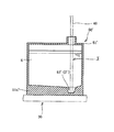
以下に添付図面を参照して、本発明に係る試薬容器の好適な実施の形態を詳細に説明する。図1は、本発明の実施の形態である試薬容器を適用した分析装置を示したものである。ここで例示する分析装置10は、血液等の検体と試薬Eとを反応させ、その反応結果に基づいて検体の分析を行うためのもので、装置本体11の上面に、反応テーブル20、試薬収容庫30および分注プローブ40を備えている。
【0016】
反応テーブル20は、円板状を成すもので、装置本体11に対して上下方向に沿った回転軸O1回りに回転可能に配設してある。この反応テーブル20には、分析対象となる検体を収容した複数の反応容器21が回転軸O1を中心とした周方向に沿って配置してある。図には明示していないが、反応テーブル20と装置本体11との間には、装置本体11に対して反応テーブル20を回転させることにより、複数の反応容器21を予め設定した吐出対象位置P1に択一的に配置させるための駆動手段が設けてある。
【0017】
試薬収容庫30は、上方に開口した円筒状を成すもので、装置本体に対して上下方向に沿った回転軸O2回りに回転可能に配設してある。試薬収容庫30の内部には、複数の試薬容器50が回転軸O2を中心とした周方向に沿って配置してある。図には明示していないが、試薬収容庫30と装置本体11との間には、装置本体11に対して試薬収容庫30を回転させることにより、複数の試薬容器50を予め設定した吸引対象位置P2に択一的に配置させるための駆動手段が設けてある。
【0018】
分注プローブ40は、先端の吸引口から流体の吸引を行うためのもので、吸引口を下方に向け、上下方向に延在する態様で分注アーム40aの先端部に取り付けてある。分注アーム40aは、その基端部に設けた支持軸40bを介して装置本体11に配設してある。支持軸40bは、装置本体11の上面から突出する態様で上下方向に沿って延設したもので、その上端部が分注アーム40aの基端部に取り付けてある。この支持軸40bは、装置本体11との間に設けた駆動手段(図示せず)の駆動により、上下方向に沿った回転軸O3回りに回転可能、かつこの回転軸O3に沿って上下方向に移動することが可能である。支持軸40bが回転軸O3回りに回転した場合には、分注プローブ40が、吐出対象位置P1に配置された反応容器21の上方域と、吸引対象位置P2に配置された試薬容器50の上方域との間を移動することができる。また、支持軸40bが上下動した場合には、分注プローブ40が、任意の位置で上下動することができる。図には明示していないが、装置本体11には、静電容量の変化に基づいて分注プローブ40の先端が試薬容器50内の試薬液面に到達したか否かを検知する検知手段が設けてある。
【0019】
一方、試薬収容庫30に配置される試薬容器50は、内部に液状の試薬Eを貯留するための容器本体51を備えている。容器本体51は、図2〜図4に示すように、底壁部51a、上壁部51b、外周壁部51c、内周壁部51dおよび一対の側壁部51eを有したもので、例えば合成樹脂によって一体に成形してある。容器本体51の底壁部51aは、円筒状を成す試薬収容庫30の内部に周方向に沿って並設するために、大小2つの同心円と径方向に沿った2つの直線とによって囲まれる略扇形状に形成してある。容器本体51の上壁部51bは、底壁部51aと同一の形状に形成したもので、一対の側壁部51eから等距離となる中心線上に分注口51fを有している。分注口51fは、上壁部51bの上面から突出する筒状部51gの中心部に開口したもので、容器本体51の内部と外部とを連通している。この分注口51fは、試薬容器50を吸引対象位置P2に配置した状態において分注プローブ40を支持軸40bの軸心回りに回転させた場合にその移動軌跡上に位置し、かつ分注プローブ40の外径よりも大きな口径を有して形成してある。なお、容器本体51の外周壁部51c、内周壁部51dおよび一対の側壁部51eは、底壁部51aおよび上壁部51bの間を連接する周囲壁部を構成するものである。
【0020】
上記容器本体51の内部には、一対の側壁部51eの間に規制板部材として仕切板52を複数並設してある。複数の仕切板52は、容器本体51を試薬収容庫30に配置した場合に、試薬収容庫30の回転軸O2を中心とした径方向に沿う態様で延設したもので、つまり回転軸O2を中心とした円の接線に直交する態様で延設したもので、それぞれの相互間がほぼ等間隔となるように並設してある。本実施の形態では、仕切板52の2つが分注口51fの下方域を相互間に挟む態様で合計4つの仕切板52を容器本体51と一体に成形してある。それぞれの仕切板52は、上端部と上壁部51bとの間に間隙を確保してある一方、左右方向の各端部が容器本体51の外周壁部51cおよび内周壁部51dに連接し、さらに下端部が容器本体51の底壁部51aに連接してあり、互いの間並びに側壁部51eとの間にそれぞれ貯留空間を画成することによって容器本体51の内部を複数(本実施の形態では5つ)に区画している。
【0021】
また、容器本体51には、底壁部51aにおいて分注口51fに対向する部位を含み、かつ底壁部51aの外周縁が成す円弧と同心の円弧状となるように連通溝53が形成してある。連通溝53は、それぞれの仕切板52に対して交差するように延在し、仕切板52によって区画された複数の貯留空間を互いに連通するための連絡通路Dを構成している。なお、連通溝53は、底壁部51aにおいて分注口51fに対向する部位を含み、かつそれぞれの仕切板52に対して交差するように延在するものであれば、円弧状に形成したものに限定されず、例えば直線状に形成したものであっても良い。
【0022】
以下、上記分析装置10において試薬容器50に貯留した試薬Eを反応容器21に分注する際の動作について説明する。分析装置10では、試薬容器50ごとに種類の異なる液状の試薬Eが貯留してあり、例えばユーザにより分析項目が選択されると、試薬収容庫30が適宜回転し、分析に必要となる試薬Eを貯留した試薬容器50が吸引対象位置P2に配置される。
【0023】
しかる後、支持軸40bが回転軸O3回りに適宜回転することにより、分注プローブ40が吸引対象位置P2に配置された試薬容器50に対して分注口51fの上方域に位置するように移動し、さらに支持軸40bが下動することにより、分注プローブ40が試薬容器50の内部に下動し、分注プローブ40の吸引口が試薬液面Efに接触した位置を検知する。試薬液面Efを検知した分注プローブ40は、検知した位置から予め設定した距離だけ下動し、必要最小限となる量だけ進入した状態から試薬Eの吸引を行う。試薬Eを吸引した分注プローブ40は、上動した後に吐出対象位置P1の上方域に位置するように移動し、吐出対象位置P1に配置されている反応容器21に試薬Eを吐出する。
【0024】
この間、試薬収容庫30の回転軸O2回りの回転によって吸引対象位置P2に配置された試薬容器50にあっては、当該回転軸O2の周方向に沿って試薬Eが流動するように慣性力が作用することになる。しかしながら、上記分析装置10で適用する試薬容器50によれば、試薬収容庫30に配置した場合に回転軸O2を中心とした径方向に沿う仕切板52が慣性力に直交し、当該仕切板52が慣性力による試薬Eの流動を妨げるように機能するため、分注プローブ40が下動する領域(以下、下動域Vという)を含む試薬Eの上下動が抑えられ、さらには上下動に伴う泡の発生が抑えられることになる。従って、移動を伴って試薬容器50が吸引対象位置P2に配置された直後であっても、試薬液面Efを正確に検知することができるため、コンタミネーションを増大させることなく規定量の試薬Eを正確に吸引し、これを反応容器21に分注することが可能となり、正確な分析処理を効率良く実施することができるようになる。
【0025】
しかも、上記試薬容器50によれば、仕切板52によって区画された複数の貯留空間が連絡通路Dによって互いに連通してあるため、分注口51fから分注プローブ40によって順次試薬Eの吸引動作を行えば、すべての貯留空間から試薬Eが吸引されることになる。従って、例えば側壁部51eの相互間隔を増大すれば、上述した作用効果を維持しつつ、容器本体51の大容量化を図ることができるようになり、試薬容器50の交換頻度、並びに試薬容器50の交換に伴うキャリブレーションの頻度も減らすことができ、分析処理のスループットを向上することが可能になる。
【0026】
なお、上述した実施の形態では、容器本体51の内部に仕切板52を4つ設けるようにしているが、分注プローブ40の下動域Vを相互間に挟む2つの仕切板52さえあれば、上述した作用効果を奏することが可能である。また、分注プローブ40の下動域Vを含む試薬Eは必ずしも2つの仕切板52の間で流動を妨げる必要はなく、容器本体51の一方の側壁部51eと仕切板52との間において流動を妨げるようにしてもよい。
【0027】
また、上述した実施の形態では、仕切板52を試薬収容庫30の回転軸O2を中心とした径方向に沿う態様で延設し、かつ左右方向の各端部を容器本体51の外周壁部51cおよび内周壁部51dに連接し、さらに下端部を容器本体51の底壁部51aに連接しているが、本発明はこれに限定されず、慣性力によって流動しようとする試薬Eが面圧を作用させるように仕切板を設ければその他の態様であってもよい。例えば、仕切板52の両端を外周壁部51cおよび内周壁部51dに連接した場合には、慣性力によって試薬Eが流動しようとする方向に交差さえしていれば、仕切板52に面圧が作用するため、必ずしも直交させる必要はない。逆に、慣性力によって試薬Eが流動しようとする方向に対して仕切板52を略直交させるように設けた場合には、両端を容器本体51の外周壁部51cおよび内周壁部51dに連接させずとも仕切板52に面圧が作用するため、必ずしも仕切板52の両端を容器本体51の周囲壁部に連接させる必要はない。
【0028】
さらに、上述した実施の形態では、仕切板52の両端を容器本体51の外周壁部51cおよび内周壁部51dに連接させた場合に、容器本体51の底壁部51aに連通溝53を形成することによって連絡通路Dを構成しているが、必ずしも連絡通路は容器本体の底壁部に形成する必要はない。例えば仕切板に貫通孔を設けることによって連絡通路を構成してもよい。なお、容器本体51の底壁部51aに連通溝53を設ける場合に上述した実施の形態では、当該連通溝53を分注プローブ40の下動域Vを含む位置に設けてあるため、連通溝53が試薬Eの液溜りとしても機能するが、必ずしも分注プローブ40の下動域Vに設ける必要はない。
【0029】
またさらに、上述した実施の形態では、吸引対象位置P2に配置された場合に、容器本体51における底壁部51aの上面がほぼ水平となるものを例示しているが、例えば、図5に示す試薬容器の変形例のように、吸引対象位置P2に配置された場合に、底壁部51a′の上面が連通溝53′に向けて漸次下方に傾斜するように容器本体51′を構成してもよい。この変形例による試薬容器50′によれば、容器本体51′の内部において残り少なくなった試薬Eが連絡通路D′に確実に収容されるようになるため、容器本体51′に貯留した試薬Eを最後まで吸引することが可能になる。
【0030】
【発明の効果】
以上説明したように、本発明に係る試薬容器によれば、少なくとも容器本体の内部において分注プローブの下動域を含む試薬の慣性力による流動を妨げる規制板部材を設けているため、分析処理のスループットを低下させることなく、規定量の試薬を正確に分注することが可能になる。
【図面の簡単な説明】
【図1】本発明の実施の形態である試薬容器を適用した分析装置の要部を示す外観斜視図である。
【図2】図1に示した分析装置で適用する試薬容器の斜視図である。
【図3】図2に示した試薬容器の平面図である。
【図4】(a)は図3におけるA−A線断面図、(b)は図3におけるB−B線断面図である。
【図5】図2に示した試薬容器の変形例を示す断面図である。
【符号の説明】
10 分析装置
11 装置本体
20 反応テーブル
21 反応容器
30 試薬収容庫
40 分注プローブ
40a 分注アーム
40b 支持軸
50,50′ 試薬容器
51,51′ 容器本体
51a,51a′ 底壁部
51b 上壁部
51c 外周壁部
51d 内周壁部
51e 側壁部
51f 分注口
51g 筒状部
52 仕切板
53,53′ 連通溝
D,D′ 連絡通路
E 試薬
O1 回転軸
O2 回転軸
O3 回転軸
P1 吐出対象位置
P2 吸引対象位置
V 分注プローブの下動域[0001]
BACKGROUND OF THE INVENTION
The present invention relates to a reagent container, and more particularly to a reagent container for storing a liquid reagent used for analysis of a sample in an analyzer.
[0002]
[Prior art]
An analyzer that performs analysis by reacting a specimen such as blood with a reagent is provided with a dispensing probe for dispensing the reagent. The dispensing probe moves between the suction target position set for the reagent container and the discharge target position set for the reaction table, and moves up and down at each of the suction target position and the discharge target position. It is provided so that it can move in the direction. The reagent storage is for arranging a plurality of reagent containers along the circumferential direction. When the reagent containers are rotationally driven, the plurality of reagent containers can be alternatively arranged at a suction target position. In each reagent container, liquid reagents necessary for analysis are individually stored. The reaction table is for arranging a plurality of reaction containers on the peripheral edge thereof, and when the rotation table is driven, the plurality of reaction containers can be alternatively arranged at the discharge target position. In each reaction container, a sample to be analyzed is dispensed in advance.
[0003]
In this analyzer, a reagent is aspirated from the reagent container arranged at the aspiration target position by appropriately operating the dispensing probe, and then the aspirated reagent is ejected to the reaction container arranged at the ejection target position. In other words, the sample can be analyzed based on the reaction results between these reagents and the sample.
[0004]
In general, an analyzer equipped with this type of dispensing probe is provided with detection means for detecting the position where the tip of the dispensing probe contacts the liquid surface of the reagent (see, for example, Patent Document 1). This is to reduce contamination by allowing the dispensing probe to enter the reagent by the minimum required amount set in advance from the liquid level detected by the detection means, and sucking the reagent from this state. It is.
[0005]
[Patent Document 1]
Japanese Patent No. 3064487 Specification [0006]
[Problems to be solved by the invention]
When the analysis item is changed, or when the reagent container is empty, the reagent container needs to be rotated. That is, when changing an analysis item, it is necessary to place a reagent container for storing a reagent corresponding to the analysis item at the position to be aspirated, and when the reagent container is empty, the reagent container storing the same reagent Must be arranged at the position to be suctioned. Here, when the reagent container is arranged at the suction target position with movement by the rotation of the reagent container, the reagent stored inside flows due to inertial force, and as a result, the liquid level of the reagent moves up and down. Will do. In addition, bubbles may be generated as the reagent liquid level moves up and down.
[0007]
In a state where the reagent liquid surface is moved up and down or bubbles are generated, it is difficult to accurately detect the reagent liquid surface by the detecting means, which may cause various problems. For example, if it is erroneously detected that the reagent liquid level is higher than the actual level, air will be mixed during the suction of the reagent, so the specified amount of reagent cannot be sucked, and the analysis results will vary. Will cause problems. On the other hand, if it is erroneously detected that the reagent liquid level is below the actual level, the amount of penetration of the dispensing probe becomes excessive, leading to an increase in contamination.
[0008]
Such a problem can be avoided by waiting until the vertical movement of the reagent liquid is stopped, or waiting until the generated bubbles disappear, and then aspirating the reagent. However, this increases the time required to dispense the reagent, which causes a reduction in the throughput of the analysis process.
[0009]
In view of the above circumstances, an object of the present invention is to provide a reagent container capable of accurately dispensing a specified amount of reagent without reducing the throughput of analysis processing.
[0010]
[Means for Solving the Problems]
In order to achieve the above object, a reagent container according to the present invention includes a container main body that stores a liquid reagent therein, and a dispensing probe that moves downward when the container main body is disposed at a suction target position. In a reagent container in which a reagent is aspirated, when the container body is moved and disposed at the position to be aspirated, the inertial force of the reagent including at least the lower movement area of the dispensing probe inside the container body It is characterized by providing a restricting plate member that hinders the flow due to.
[0011]
Moreover, the reagent container according to the present invention is characterized in that, in the above-described invention , the regulating plate member is arranged in a manner that intersects the flow direction of the reagent due to inertial force.
[0012]
Further, the reagent container according to the present invention is the above-described invention , wherein the inside of the container body is partitioned into a plurality of storage spaces by connecting both ends of the regulating plate member to the peripheral wall part of the container body, and The plurality of storage spaces are connected to each other by a communication passage.
[0013]
In the reagent container according to the present invention , in the above-described invention , the communication path includes a portion corresponding to a lower moving area of the dispensing probe when the container body is disposed at the suction target position. It is a communicating groove formed in the bottom wall of the container body.
[0014]
In the reagent container according to the present invention , in the above-described invention , when the bottom wall portion of the container body is disposed at the suction target position, the upper surface of the container body faces downward toward the communication groove. Inclined.
[0015]
DETAILED DESCRIPTION OF THE INVENTION
Exemplary embodiments of a reagent container according to the present invention will be described below in detail with reference to the accompanying drawings. FIG. 1 shows an analyzer to which a reagent container according to an embodiment of the present invention is applied. The
[0016]
The reaction table 20 has a disk shape, and is disposed so as to be rotatable around the rotation axis O 1 along the vertical direction with respect to the apparatus
[0017]
The
[0018]
The dispensing
[0019]
On the other hand, the
[0020]
Inside the container
[0021]
Further, the
[0022]
Hereinafter, an operation when dispensing the reagent E stored in the
[0023]
Thereafter, by the
[0024]
During this time, as In the rotary shaft O 2 around the
[0025]
Moreover, according to the
[0026]
In the above-described embodiment, four
[0027]
Further, in the above-described embodiment, the
[0028]
Furthermore, in the above-described embodiment, when both ends of the
[0029]
Furthermore, in the embodiment described above, when placed in the suction target position P 2, it is exemplified what the upper surface of the
[0030]
【The invention's effect】
As described above, according to the reagent container of the present invention, the restriction plate member that prevents flow due to the inertial force of the reagent including the lower movement region of the dispensing probe is provided at least inside the container main body. It is possible to accurately dispense a specified amount of reagent without reducing the throughput of the.
[Brief description of the drawings]
FIG. 1 is an external perspective view showing a main part of an analyzer to which a reagent container according to an embodiment of the present invention is applied.
FIG. 2 is a perspective view of a reagent container to be applied in the analyzer shown in FIG.
3 is a plan view of the reagent container shown in FIG. 2. FIG.
4A is a cross-sectional view taken along line AA in FIG. 3, and FIG. 4B is a cross-sectional view taken along line BB in FIG.
5 is a cross-sectional view showing a modification of the reagent container shown in FIG.
[Explanation of symbols]
DESCRIPTION OF
Claims (4)
前記容器本体は、円筒状をなす試薬収容庫内部に周方向に沿って円環状に配置され、該容器本体内部は、前記試薬収容庫の回転軸を中心とする径方向に沿って延設された板状の規制板部材が設けられ、該規制板部材の両端をそれぞれ前記容器本体の周囲壁部に連接することによって該容器本体の内部を複数の貯留空間に区画したことを特徴とする試薬容器。In a reagent container that includes a container main body that stores a liquid reagent therein, and the reagent is aspirated by a dispensing probe that moves downward when the container main body is disposed at a position to be aspirated,
The container body is annularly arranged along a circumferential direction inside a cylindrical reagent container, and the container body is extended along a radial direction centering on the rotation axis of the reagent container. A plate-shaped regulating plate member is provided, and the inside of the container body is partitioned into a plurality of storage spaces by connecting both ends of the regulating plate member to the peripheral wall portion of the container body, respectively. container.
Priority Applications (1)
| Application Number | Priority Date | Filing Date | Title |
|---|---|---|---|
| JP2003184385A JP4225848B2 (en) | 2003-06-27 | 2003-06-27 | Reagent container |
Applications Claiming Priority (1)
| Application Number | Priority Date | Filing Date | Title |
|---|---|---|---|
| JP2003184385A JP4225848B2 (en) | 2003-06-27 | 2003-06-27 | Reagent container |
Publications (2)
| Publication Number | Publication Date |
|---|---|
| JP2005017176A JP2005017176A (en) | 2005-01-20 |
| JP4225848B2 true JP4225848B2 (en) | 2009-02-18 |
Family
ID=34184172
Family Applications (1)
| Application Number | Title | Priority Date | Filing Date |
|---|---|---|---|
| JP2003184385A Expired - Fee Related JP4225848B2 (en) | 2003-06-27 | 2003-06-27 | Reagent container |
Country Status (1)
| Country | Link |
|---|---|
| JP (1) | JP4225848B2 (en) |
Families Citing this family (6)
| Publication number | Priority date | Publication date | Assignee | Title |
|---|---|---|---|---|
| JP5409564B2 (en) * | 2010-09-16 | 2014-02-05 | 株式会社日立ハイテクノロジーズ | Automatic analyzer |
| US10058866B2 (en) | 2013-03-13 | 2018-08-28 | Abbott Laboratories | Methods and apparatus to mitigate bubble formation in a liquid |
| USD978375S1 (en) | 2013-03-13 | 2023-02-14 | Abbott Laboratories | Reagent container |
| USD962471S1 (en) | 2013-03-13 | 2022-08-30 | Abbott Laboratories | Reagent container |
| US9535082B2 (en) | 2013-03-13 | 2017-01-03 | Abbott Laboratories | Methods and apparatus to agitate a liquid |
| WO2017067873A1 (en) * | 2015-10-20 | 2017-04-27 | Roche Diagnostics Gmbh | Reagent vessel for storing a liquid reagent, apparatus for manufacturing a lower part of a reagent vessel and a method for manufacturing a lower part of a reagent vessel |
-
2003
- 2003-06-27 JP JP2003184385A patent/JP4225848B2/en not_active Expired - Fee Related
Also Published As
| Publication number | Publication date |
|---|---|
| JP2005017176A (en) | 2005-01-20 |
Similar Documents
| Publication | Publication Date | Title |
|---|---|---|
| EP1460432B1 (en) | Sample dispensing apparatus and automatic analyzer including the same | |
| US8043562B2 (en) | Analyzer having removable holders or a centrifuge | |
| JP5744923B2 (en) | Automatic analyzer | |
| US8596150B2 (en) | Analytical device with mixing cavity | |
| JP2021043208A (en) | Methods and apparatus for mitigating bubble formation in liquid | |
| JP4225848B2 (en) | Reagent container | |
| JP6919535B2 (en) | Dispenser | |
| EP1225450A1 (en) | Reagent dispensing or filling apparatus and holder | |
| JP5860725B2 (en) | Automatic analyzer | |
| JP2002228670A (en) | Method and apparatus for supplying very small amount of liquid, and apparatus for mixing the very small amount of liquid | |
| JP2011163771A (en) | Syringe pump, dispensing device, and automatic analyzer | |
| WO2012111287A1 (en) | Specimen container and nozzle tip volume regulator | |
| JP4475570B2 (en) | Centrifuge built-in analyzer | |
| JPS63182040A (en) | Reagent receiving container | |
| JPH11304817A (en) | Dispenser | |
| JP7110222B2 (en) | Automated analyzer and probe cleaning method | |
| JP2008517255A (en) | Pipette device | |
| JP3141577U (en) | Reagent container | |
| CN113677998A (en) | Automatic analyzer | |
| JP4393481B2 (en) | Automatic analyzer | |
| JP6815801B2 (en) | Automatic analyzer | |
| JP2002048801A (en) | Autoanalyzer | |
| JP2010117176A (en) | Analyzer and dispensation controlling method therefor | |
| WO2022259765A1 (en) | Automatic analysis device | |
| JP3069211B2 (en) | Biochemical analysis method |
Legal Events
| Date | Code | Title | Description |
|---|---|---|---|
| A621 | Written request for application examination |
Free format text: JAPANESE INTERMEDIATE CODE: A621 Effective date: 20060627 |
|
| A977 | Report on retrieval |
Free format text: JAPANESE INTERMEDIATE CODE: A971007 Effective date: 20080501 |
|
| A131 | Notification of reasons for refusal |
Free format text: JAPANESE INTERMEDIATE CODE: A131 Effective date: 20080520 |
|
| A521 | Written amendment |
Free format text: JAPANESE INTERMEDIATE CODE: A523 Effective date: 20080722 |
|
| A131 | Notification of reasons for refusal |
Free format text: JAPANESE INTERMEDIATE CODE: A131 Effective date: 20080812 |
|
| A521 | Written amendment |
Free format text: JAPANESE INTERMEDIATE CODE: A523 Effective date: 20081014 |
|
| TRDD | Decision of grant or rejection written | ||
| A01 | Written decision to grant a patent or to grant a registration (utility model) |
Free format text: JAPANESE INTERMEDIATE CODE: A01 Effective date: 20081104 |
|
| A01 | Written decision to grant a patent or to grant a registration (utility model) |
Free format text: JAPANESE INTERMEDIATE CODE: A01 |
|
| A61 | First payment of annual fees (during grant procedure) |
Free format text: JAPANESE INTERMEDIATE CODE: A61 Effective date: 20081125 |
|
| FPAY | Renewal fee payment (event date is renewal date of database) |
Free format text: PAYMENT UNTIL: 20111205 Year of fee payment: 3 |
|
| FPAY | Renewal fee payment (event date is renewal date of database) |
Free format text: PAYMENT UNTIL: 20111205 Year of fee payment: 3 |
|
| FPAY | Renewal fee payment (event date is renewal date of database) |
Free format text: PAYMENT UNTIL: 20111205 Year of fee payment: 3 |
|
| S111 | Request for change of ownership or part of ownership |
Free format text: JAPANESE INTERMEDIATE CODE: R313113 |
|
| FPAY | Renewal fee payment (event date is renewal date of database) |
Free format text: PAYMENT UNTIL: 20111205 Year of fee payment: 3 |
|
| R350 | Written notification of registration of transfer |
Free format text: JAPANESE INTERMEDIATE CODE: R350 |
|
| FPAY | Renewal fee payment (event date is renewal date of database) |
Free format text: PAYMENT UNTIL: 20111205 Year of fee payment: 3 |
|
| FPAY | Renewal fee payment (event date is renewal date of database) |
Free format text: PAYMENT UNTIL: 20121205 Year of fee payment: 4 |
|
| FPAY | Renewal fee payment (event date is renewal date of database) |
Free format text: PAYMENT UNTIL: 20131205 Year of fee payment: 5 |
|
| R250 | Receipt of annual fees |
Free format text: JAPANESE INTERMEDIATE CODE: R250 |
|
| R250 | Receipt of annual fees |
Free format text: JAPANESE INTERMEDIATE CODE: R250 |
|
| R250 | Receipt of annual fees |
Free format text: JAPANESE INTERMEDIATE CODE: R250 |
|
| R250 | Receipt of annual fees |
Free format text: JAPANESE INTERMEDIATE CODE: R250 |
|
| LAPS | Cancellation because of no payment of annual fees |