JP4222697B2 - Dishwasher - Google Patents
Dishwasher Download PDFInfo
- Publication number
- JP4222697B2 JP4222697B2 JP29297899A JP29297899A JP4222697B2 JP 4222697 B2 JP4222697 B2 JP 4222697B2 JP 29297899 A JP29297899 A JP 29297899A JP 29297899 A JP29297899 A JP 29297899A JP 4222697 B2 JP4222697 B2 JP 4222697B2
- Authority
- JP
- Japan
- Prior art keywords
- rack
- carry
- cleaning
- cleaned
- cleaning chamber
- Prior art date
- Legal status (The legal status is an assumption and is not a legal conclusion. Google has not performed a legal analysis and makes no representation as to the accuracy of the status listed.)
- Expired - Fee Related
Links
- 238000004140 cleaning Methods 0.000 claims description 185
- 210000000078 claw Anatomy 0.000 claims description 42
- XLYOFNOQVPJJNP-UHFFFAOYSA-N water Substances O XLYOFNOQVPJJNP-UHFFFAOYSA-N 0.000 description 66
- 238000005406 washing Methods 0.000 description 34
- 238000000034 method Methods 0.000 description 8
- 239000008237 rinsing water Substances 0.000 description 7
- 238000001514 detection method Methods 0.000 description 6
- 238000010586 diagram Methods 0.000 description 6
- 239000003638 chemical reducing agent Substances 0.000 description 3
- 239000007788 liquid Substances 0.000 description 3
- 238000003825 pressing Methods 0.000 description 3
- 238000010438 heat treatment Methods 0.000 description 2
- 238000007689 inspection Methods 0.000 description 2
- 238000005259 measurement Methods 0.000 description 2
- 238000005507 spraying Methods 0.000 description 2
- 238000011109 contamination Methods 0.000 description 1
- 239000003599 detergent Substances 0.000 description 1
- 230000000694 effects Effects 0.000 description 1
- 238000012423 maintenance Methods 0.000 description 1
- 238000005192 partition Methods 0.000 description 1
- 239000007921 spray Substances 0.000 description 1
Images


Landscapes
- Washing And Drying Of Tableware (AREA)
Description
【0001】
【発明の属する技術分野】
本発明は、食器などの被洗浄物を洗浄する食器洗浄機に関する。
【0002】
【従来の技術】
従来、この種食器洗浄機は、実公平1−35705号公報(A47L15/42)に示す如く、食器をラック内に収納し、このラックを、搬送コンベアを介して洗浄室フード内に搬入し、洗浄液噴射管からの洗浄液の噴射によって食器を洗浄する構造が開示されている。
【0003】
一般的に、この様な被洗浄物を搬送コンベアなどで搬入側から搬出側に搬送しながら洗浄する食器洗浄機をコンベアタイプと称し、搬入口から被洗浄物を収納したラックを押し込む事によって、搬送コンベアは搬出側に搬送し、その搬送段階で常時噴射されている洗浄液によって洗浄するものである。この様なコンベアタイプの食器洗浄機は、ラックを押し込むだけであるため、使い勝手が良いものである。
【0004】
【発明が解決しようとする課題】
上述した様なコンベアタイプの食器洗浄機は、すすぎ水が出っ放しになるため、洗浄開始時などにすすぎ水が無駄に使われる等の問題があった。
【0005】
本発明は上述した問題点に鑑みてなされたもので、コンベアタイプの使い勝手の良さで、消費水量の低減を図る事を目的とした食器洗浄機を提供する。
【0006】
【課題を解決するための手段】
上記目的を達成するための手段として、本発明の食器洗浄機は、食器などの被洗浄物を洗浄する洗浄室と、この洗浄室の一方側に形成され被洗浄物を収納したラックを洗浄室へ搬入する搬入口と、この洗浄室の他方側に形成され被洗浄物を収納したラックを洗浄室から搬出する搬出口と、前記搬入口から前記搬出口へ向かう長手方向に爪を配列し、前記ラックの搬入側へ移動するとき前記爪が前記ラックに引っかからず、搬出側へ移動するとき前記爪が前記ラックに引っかかって前記ラックを搬出方向へ運ぶコンベア装置と、前記ラックの搬入時には前記コンベア装置を搬入側が上方となるように傾斜させ、前記ラックの搬出時には搬入側のラックの搬入を防止するよう前記爪が搬入側のラックに引っかからない状態に前記コンベア装置を搬入側が下方となるように傾斜させる傾斜装置とを備えたことを特徴とする。
また、本発明の食器洗浄機は、食器などの被洗浄物を洗浄する洗浄室と、この洗浄室の一方側に形成され被洗浄物を収納したラックを洗浄室へ搬入する搬入口と、この洗浄室の他方側に形成され被洗浄物を収納したラックを洗浄室から搬出する搬出口と、前記搬入口から前記搬出口へ向かう長手方向に爪を配列したロッドと、このロッドを揺動自在に保持するロッドガイドとよりなるコンベア装置と、前記ロッドを前記ラックの搬入側へ移動した時前記爪が搬出側へ倒れて前記ラックの下面へすべり込み前記ラックに引っかからず、前記ロッドを搬出側へ移動した時前記爪が前記ラックの下面引っかかって前記ラックを搬出方向へ運ぶように前記コンベア装置を揺動する揺動装置と、前記ラックの搬入時には前記揺動装置に連結された前記コンベア装置を搬入側が上方となるように傾斜させ、前記ラックの搬出時には搬入側のラックの搬入を防止するよう前記爪が搬入側のラックに引っかからない状態に前記揺動装置に連結された前記コンベア装置を搬入側が下方となるように傾斜させる傾斜装置とを備えたことを特徴とする。
【0007】
この様に、コンベア装置を搬入側及び搬出側双方に傾斜可能としたため、ラック搬入時には、コンベア装置を搬入側が上方となるよう傾斜させ、ラック搬出時には、逆に搬入側が下方となり、コンベア装置のラックの搬入を防止できる。
【0012】
【発明の実施の形態】
以下、本発明の実施の形態を図面に基づいて説明する。
図1は本発明を具備する食器洗浄機の正面図、図2は食器洗浄機の断面図、図3はラック搬入側の食器洗浄機の斜視図、図4はラックを搬出入するコンベア装置の分解斜視図、図5はフルサイズラック搬入時のコンベア装置の正面図、図6はフルサイズラック洗浄時のコンベア装置の正面図、図7はハーフサイズラック搬入時のコンベア装置の正面図、図8は2つのハーフサイズラック搬入時におけるコンベア装置の正面図、図9は2つのハーフサイズラック搬出時におけるコンベア装置の正面図、図10はコンベア装置の側断面図、図11はコンベア装置の揺動機構の拡大図、図12はハーフサイズラックの後にフルサイズラックを搬入した時のコンベア装置の正面図、図13はラック搬出側の食器洗浄機の斜視図、図14は搬出側カーテンの斜視図、図15は食器洗浄機搬出側の拡大図、図16はカーテン洗浄装置の斜視図、図17は扉安全スイッチの平面図、図18は扉安全スイッチの正面図、図19はオーバーフロー構造を示す要部拡大図、図20はラック搬入時の動作説明図、図21はラック洗浄時の動作説明図、図22はラック搬出時の動作説明図、図23は本発明の食器洗浄機の制御を示すフローチャート、図24は図23の続きを示すフローチャート、図25は前回電源OFF時に洗浄サイクル運転中であった場合のフローチャート、図26は前回電源OFF時にラック搬出運転中であった場合のフローチャートである。
【0013】
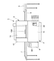
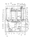
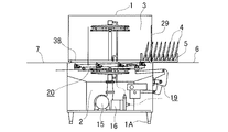
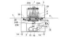
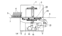
図1及び図2における1は本発明を具備する食器洗浄機本体で、この食器洗浄機1の下部には機械室2が形成されており、食器洗浄機1の上部には洗浄室3が形成されている。
【0014】
また、この食器洗浄機1の右側には、被洗浄物4、即ち皿や食器などを収納するラック5を載置するためのラック搬入台6が設けられている。更に、左側には、洗浄後のラック5が搬出されるラック搬出台7が設けられている。このラック5は、長さが500mmのフルサイズラック5Aと、長さが250mmのハーフサイズラック5Bとがあり、奥行きは同じサイズに形成されている。
【0015】
そして、この食器洗浄機1の左側であって、前記ラック搬出台7の下には、すすぎのためのブースタータンク8が設けられており、図示しないが、内部に電気ヒータやガスバーナーなどの加熱装置が設けられている。更に、ブースタータンク8内には水温計が設けられており、通常、水温は約80℃に保温されている。尚、8Aはブースタータンク8の給湯を制御する給湯コントロールパネルである。
【0016】
また、食器洗浄機1下部、即ち機械室2は、4本のL型フレームを四辺形に組み合わせてなる底部9と、この底部9の四隅にL型フレームを直立させてなる側部10と、この側部10のL型フレーム間に設けられる側面パネル11とで画成されている。
【0017】
更に、前記低部9の下面の四隅には、食器洗浄機1を支持する台脚1Aが取り付けられており、この台脚1Aは上下方向の高さ調整が可能となっている。
【0018】
また、前記洗浄室3は洗浄室パネル12にて画成されており、洗浄室パネル12の略中央部分、即ち洗浄室3の洗浄エリア3Aに対応する位置には、少なくとも前記フルサイズラック5Aより大きな開口が形成されている。そして、この開口は、上下方向にスライド移動可能な洗浄室扉13にて開閉自在に閉塞されている。尚、13Aは洗浄室扉13の下部に取り付けられた把手である。
【0019】
次に、前記機械室2の内部構造について説明する。
この機械室2の内部には、洗浄を行うための洗浄水を貯留する洗浄水タンク14が設けられており、この洗浄水タンク14には洗浄ポンプ15が取り付けられている。
【0020】
また、この洗浄ポンプ15の左側には、前記ブースタータンク8のすすぎ水のためのすすぎポンプ16が設けられている。更に、洗浄ポンプ15の右側には、減速機17、クランク機構18を含む揺動装置19が設けられている。
【0021】
この揺動装置19は、前記ラック5を搬送するため、前記洗浄室3に位置するコンベア装置20を揺動させるものである。そして、前記すすぎポンプ16の左側には、このコンベア装置20を右傾斜、及び左傾斜させる傾斜装置21が設けられている。
【0022】
更に、図1に示す如く、機械室2の右下部には、コントロールパネル22が設けられている。そして、このコントロールパネル22にはダイヤル式の切換スイッチ22Aが設けられており、「手動洗い」、「自動」、「OFF」、「手動すすぎ」の順に切換えられる様になっている。この切換スイッチ22Aの他、コントロールパネル22には、洗浄水温度を表示する温度表示器22B、洗浄が可能であるか否かを示す洗浄可能ランプ22C、点検が必要な場合に点灯する点検ランプ22Dがそれぞれ配置されている。
【0023】
次に、前記洗浄室3の内部構造について説明する。
この洗浄室3の洗浄エリア3Aには、搬入された被洗浄物4をラック5ごと洗浄する上下一対の回転洗浄ノズル23A、23Bと、これら上下回転洗浄ノズル23A、23Bの内側、即ち上洗浄ノズル23Aの下側には上回転すすぎノズル24A、下洗浄ノズル23Bの上側には、下回転すすぎノズル24Bがそれぞれ設けられている。
【0024】
この様に、洗浄及びすすぎに用いるノズルを回転式とし、且つ上下一対設けたため、洗浄、すすぎ時に被洗浄物の隅々まで洗浄することができ、被洗浄物を衛生的に扱う事ができる。
【0025】
また、この上回転すすぎノズル24Aには、上回転洗浄ノズル23Aが回転する際、上回転すすぎノズル24Aと重なって上回転すすぎノズル24Aの下方に洗浄水が行き渡らないという事を防止するため、回転同期棒24Cが設けられている。これにより、上回転洗浄ノズル23Aと上回転すすぎノズル24Aとは常にずれた状態となり、確実に洗浄水をラック5の被洗浄物4に噴出させる事ができる。
【0026】
尚、本実施形態において、この回転同期棒24Cは上回転すすぎノズル24Aに設けているが、上回転洗浄ノズル23Aに設けても良い。更に、上回転すすぎノズル24A或いは上回転洗浄ノズル23Aに加え、下回転すすぎノズル24B或いは下回転洗浄ノズル23Bに設けても良い。
【0027】
更に、上下回転洗浄ノズル23A、23B及び上下回転すすぎノズル24A、24Bの間であって、下回転洗浄ノズル23B及び下回転すすぎノズル24B側、即ち洗浄室3の下部には前記コンベア装置20が位置している。
【0028】
そして、前記洗浄水タンク14内の洗浄水を、前記上下回転洗浄ノズル23A、23Bに供給するため、前記機械室2、洗浄室3に跨って配置された洗浄水供給管25が、前記上下回転洗浄ノズル23A、23Bと洗浄ポンプ15とを接続している。
【0029】
尚、前記洗浄水タンク14内には、電気ヒータなどの加熱装置が設けられており、洗浄水は約60℃の温度に保温されている。
【0030】
更に、前記ブースタータンク8内のすすぎ水を前記上下回転すすぎノズル24A、24Bに供給するため、前記機械室2、洗浄室3に跨って配置されたすすぎ水供給管26が、前記上下回転すすぎノズル24A、24Bとすすぎポンプ16とを接続している。
【0031】
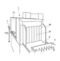
また、前記洗浄室パネル12の右側面には、図3に示す如く、ラック5を搬入するため搬入口27が形成され、左側面にはラック5を搬出するための搬出口28が形成されている。
【0032】
そして、この搬入口27には、短冊状に複数枚分割された搬入側カーテン29が吊下しており、洗浄エリア3Aの搬出側には、搬出側カーテン30が吊下している。
【0033】
これらの搬入側カーテン29及び搬出側カーテン30は、洗浄水、すすぎ水が外に飛び散ってしまう事を防止すると共に、洗浄、すすぎ後の被洗浄物に汚れた洗浄水が飛び散ってしまう事を防止するために設けられている。
【0034】
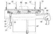
また、洗浄室3内には、搬入口27側に設けられた搬入スイッチ部31と、この搬入スイッチ部31より洗浄エリア3A側に設けられたラック検出スイッチ部32と、前記洗浄エリア3Aの搬出側カーテン30近傍に設けられた洗浄スイッチ部33と、前記搬出口28近傍に設けられた搬出スイッチ部34とがそれぞれ設けられている。
【0035】
これらの各スイッチ部31、32、33、34は、上下方向に延在し、回動可能な軸部材35、35…と、これら軸部材35、35…の下部に設けられ、前記ラック5が当接する当接部36、36…と、前記軸部材35、35…に接続され、食器洗浄機1の上部であって、洗浄室3外に設けられた搬入スイッチ31A、ラック検出スイッチ32A、洗浄スイッチ33A、搬出スイッチ34Aとよりなる。
【0036】
従って、ラック5が移動する事により、ラック5が前記当接部36、36…に当接して軸部材35が回動し、各スイッチ31A、32A、33A、34Aを入切りする事となる。
【0037】
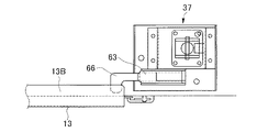
また、前記洗浄室3外には、前記洗浄室扉13の上縁13Bにて入切りされる扉スイッチ部37が設けられている。
【0038】
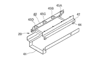
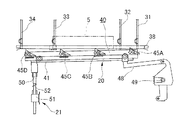
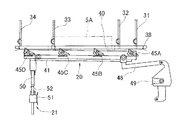
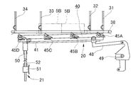
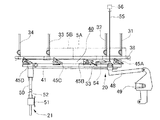
次に、コンベア装置20について図4乃至図12を参照して詳細に説明する。尚、38はコンベア装置20の近傍に位置し、前記ラック5を搬出方向に案内する一対のラックレールで、断面L字状のレールを対向位置させてなるものである。
【0039】
このコンベア装置20は、前記ラック5を搬送するロッド40と、このロッド40を揺動自在に保持するロッドガイド41とよりなり、前記ロッド40は前記揺動装置19にて揺動可能であって、ロッドガイド41は、前記ラックレール38に対して前記傾斜装置21にて傾斜可能となっている。
【0040】
そして、このロッド40は、枠状に形成された枠部材42と、この枠部材42の下部に設けられ、前記ロッドガイド41に対して転動するローラ44、44…と、ロッド40の上部に設けられ、略三角形をなす一対の第一、第二、第三、第四爪45A、45B、45C、45Dとよりなるものである。
【0041】
本実施形態では、これら一対の第一乃至第四爪45A、45B、45C、45Dを長手方向に4箇所、計8個設けている。そして、ラック搬入側から2箇所の第一及び第二爪45A、45Bは、ラック搬入用として用い、ラック搬出側から3個所の第二乃至第四爪45B、45C、45Dはラック搬出用として用いる。
【0042】
即ち、ラック搬入側から2箇所目の第二爪45Bは、ラック5の搬入及び搬出両方に用いられるものである。
【0043】
そして、これら第一乃至第四爪45A、45B、45C、45Dは、ラック搬入方向に下方傾斜していると共に、回動可能に取り付けられており、第一乃至第四爪45A、45B、45C、45Dの下側には、各爪45の回動を規制する回動規制板46が延在している。
【0044】
従って、前記ロッド40をラック5の搬入出方向に揺動する事で、搬入側へ移動した時には、爪45が搬出側に倒れ、ラック5の下面へすべり込み、搬出側へ移動した時には、爪45が回動規制板46に当たり、それ以上の回動を規制してロックするため、ラック5の下面に爪45の頂部が引っかかって、ラック5を搬出方向へ運ぶ事となる。
【0045】
この様に、単一のコンベア装置20でもって、ラック5の搬入、搬出を両方行う事ができ、更に、ラック5が搬出されなければ次のラック5が搬入される事が無いため、被洗浄物4を確実に洗浄できると共に、洗浄済み被洗浄物4を次の洗浄動作時の洗浄水で汚してしまう事を防止する事ができる。
【0046】
また、ラックが洗浄室3内の所定位置に搬入された時点で、洗浄サイクル運転を行うため、ランニングコストを低く抑えることができる。
【0047】
次に、前記ロッド40を揺動させる揺動装置19は、図示しない電動モータの回転速度を減速する減速機17を備え、この減速機17の回転運動をクランク機構18にて直線運動に変換する。
【0048】
このクランク機構18には、第一連結棒47が設けられ、この第一連結棒47は前記ロッド40に接続された第二連結棒48に連結具49を介して接続されている。
【0049】
従って、揺動装置19を駆動させる事により、第一連結棒47がラック5の搬入出方向に所定の振幅で駆動し、連結具49を介して第二連結棒48が同方向に駆動して前記ロッド40をラック搬入出方向に揺動させる事となる。
【0050】
尚、本実施形態では、この第二連結棒48はロッド40の第一爪45A近傍に接続されているが、ロッド40を揺動する事ができれば、接続位置は限定されないものとする。
【0051】
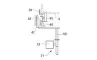
次に、前記ロッドガイド41を傾斜させる傾斜装置21は、ロッドガイド41の搬出側の端部に接続されたロッド傾斜具50と、このロッド傾斜具50を上下動させるリニアモータ51とからなり、このロッド傾斜具50は前記洗浄水タンク14の一部を貫通している。
【0052】
更に、ロッド傾斜具50の洗浄水タンク14より下方には、洗浄水タンク14からの水漏れ、外面への水滴の発生などを考慮し、下方傾斜状の庇52が設けられている。
【0053】
そして、ロッドガイド41は前記第二爪45Bの位置を中心に傾斜可能となっている。従って、第二爪45Bは、前述した如くラック5の搬入時及び搬出時のいずれにおいてもラック5の下面に引っかかる事となる。
【0054】
但し、最初にハーフサイズラック5B、次にフルサイズラック5Aを一度に入れた場合、最初のハーフサイズラック5Bは全ての被洗浄物4を洗浄する事ができるが、次のフルサイズラック5Aは、前半の被洗浄物4しか洗浄することができないという事態になる。
【0055】
従って、この場合、図12に示す如く、第二爪45Bを倒して最初のハーフサイズラック5Bのみ搬出し、フルサイズラック5Aを再び洗浄する。
【0056】
この機構は、前記第二爪45Bの下方傾斜端を上方に押し上げるため、略中心を支点として回動可能なワイヤー状の爪押部53と、この爪押部53の第二爪45Bとは反対側の端部を押し下げるため、略中心を支点として回動可能とした板状部54と、この板状部54の爪押部53とは反対側に接続されたワイヤー55と、このワイヤー55に接続されたソレノイド56とよりなる。
【0057】
従って、ハーフサイズラック5Bの後にフルサイズラック5Aがあれば、前記ラック検出スイッチ部32がフルサイズラック5Aを検出するため、この検出により、ソレノイド56がワイヤー55を引き上げ、板状部54の爪押部53側が下方に下がり、爪押部53の第二爪45B側が上方に回動し、第二爪45Bが倒れて、フルサイズラック5Aに引っかからなくなる。以って、フルサイズラック5Aの搬出は防止される事となる。
【0058】
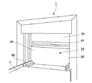
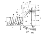
次に図13乃至図15を参照して、前記搬出側カーテン30について説明する。
【0059】
この搬出側カーテン30は、前記洗浄エリア3Aの搬出側に垂下した区画板57に取り付け、搬出方向に回動可能な取付部58と、この取付部58に固定され、厚さ3mmの軟質シートにて形成された上シート59と、この上シート59と重合して接続し、厚さ1mmの軟質シートにて形成された下シート60と、この下シート60と上シート59の重合部分に設けられたウエイト61とよりなる。
【0060】
更に、少なくとも下シート60は一枚物で形成し、下部の左右両端には前記ラックレール38の形状に合わせた切欠60Aが形成されている。
【0061】
そして、搬出側カーテン30は、被洗浄物4を収納したラック5の搬出時、図15に示す如く、回動支点である取付部58から上シート59下辺までの距離Aを、取付部58から下シート60の被洗浄物4に当たるまでの距離Bより短く形成する。
【0062】
具体的には、ラック5に被洗浄物4を載置した状態の高さ、即ちラック底面から被洗浄物上端までの高さCが350mm、ラックレール38のラック載置面から前記取付部58までの高さDを450mm、搬出側カーテン30から搬出時の被洗浄物最後端までの距離Eが240mmである場合、搬出側カーテン30の上シート59の長さAを210mm、上シート59の最下端から下シート60の最下端までの長さFを270mmとする。
【0063】
以上の如き構成によって、上シート59と下シート60の重合部に設けられたウエイト61は被洗浄物4に当たることがなく、且つウエイト61の重さでラック搬出後、確実に搬出側カーテン30は垂下する事となる。従って、洗浄サイクル運転時には確実に搬出側カーテン30が垂下している状態となる。
【0064】
また、搬出側カーテン30を複数枚に区切り短冊状に形成した場合、その切れ目に汚れが付着する恐れがあるが、本実施形態の搬出側カーテン30は、少なくとも被洗浄物4と当たる下シート60を一枚物とする事により、搬出側カーテン30自体への汚れの付着を極力防止できる。このため、洗浄後の被洗浄物4に、搬出側カーテン30の汚れが付着してしまう事を極力防止でき、被洗浄物4を衛生的に扱う事ができる。
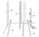
【0065】
更に、この搬出側カーテン30近傍の洗浄エリア3A側には、搬出側カーテン30の汚れを落とすため、カーテン洗浄装置、即ちカーテンすすぎノズル62を設ける。
【0066】
このカーテンすすぎノズル62は前記すすぎ水供給管26に接続されており、前記上下回転すすぎノズル24A、24Bと同時にすすぎ水を搬出側カーテン30に噴射するものである。
【0067】
この様に、洗浄後の被洗浄物4と接触する搬出側カーテン30の洗浄エリア3A側を、洗浄サイクル運転毎にすすぐため、搬出側カーテン30への残滓や汚れの付着を極力防止する事ができ、被洗浄物4を衛生的に扱う事ができる。
【0068】
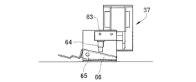
次に扉スイッチ37について図17及び図18を参照して詳細に説明する。
【0069】
この扉スイッチ37は、扉スイッチ本体63と、この扉スイッチ本体63に設けられ、図示しないバネなどの付勢装置、及び自重にて下方に突出しているボタン64と、このボタン64を上方に押し上げるため、支点65を中心にしてシーソー状となっていると共に、ボタン64側を重くしたアーム66とよりなるものである。
【0070】
そして、通常の洗浄室扉13閉塞時には、洗浄室扉13の上縁13Bが前記アーム66の一端側を下方に押し下げ、他端が上方に押し上げられている状態となっている。この状態では、前記扉スイッチ本体63のボタン64が、バネの付勢力に抗して上方に押され、洗浄サイクル運転が可能な状態となっている。
【0071】
また、清掃、メンテナンス、ラック5の詰まりなどの不具合が生じて、洗浄室扉13を開放する場合、前記アーム66が洗浄室扉13の上縁13Bによる押下を解除され、前記支点65を中心にアーム66の他端が自重にて下方に下がる。これに伴って、前記ボタン64がバネ及び自重によって下方に突出し、洗浄サイクル運転が不可能な状態となる。
【0072】
以上の如く、洗浄室扉13を開放すると洗浄サイクル運転を不可とするため、洗浄室扉13を開放している状態で誤って洗浄サイクル運転のスイッチを入れてしまっても動作しない。
【0073】
更に、洗浄サイクル運転中に誤って洗浄室扉13を開放しても、洗浄サイクル運転はすぐに停止するため、食器洗浄機1の周囲に、洗浄水などが飛散してしまう事を極力防止できる。
【0074】
従って、食器洗浄機1の周囲を汚してしまう事を防止できると共に、食器洗浄機1に搭載している電装部品などに水がかかって故障してしまうなどのトラブルを未然に回避できる。以って、食器洗浄機1の信頼性向上を図る事となる。
【0075】
次に、前記洗浄水タンク14について図19を参照して説明する。
洗浄水タンク14の上部には、図示しないが、大きな残滓を除去するためのフィルター、及び洗浄水の水位を検出するための水位検出スイッチが設けられており、更に下部には、洗浄水を所定水位に保つためのオーバーフロー管67が設けられている。
【0076】
特に業務用の食器洗浄機1である場合、洗浄水中に大きな残滓が入り込み、オーバーフロー管67を詰まらせてしまう可能性がある。
【0077】
従って、このオーバーフロー管67以外に、オーバーフロー部68を形成する。本実施形態では、特に洗浄ポンプ15、すすぎポンプ16、リニアモータ51などの電装部品が無い洗浄水タンク14の右側の一部を切り欠いてオーバーフロー部68を形成している。
【0078】
尚、このオーバーフロー部68は洗浄水タンク14の電装部品が無い場所であればどこでも良く、更にオーバーフロー部68は洗浄水タンク14の一部を切り欠く他、丸穴、角穴を形成しても良いし、別途補助オーバーフロー管などの筒を接続しても良い。この補助オーバーフロー管を設ける場合、少なくとも前記オーバーフロー管67より径大な筒を用いる事が望ましい。
【0079】
以上の如く構成することにより、通常では図19に示す二点鎖線で示す水位以上はあがらず、仮にオーバーフロー管67が残滓などによって詰まった場合でも、図中点線で示す水位以上あがらない。
【0080】
従って、例えオーバーフロー管67が詰って水位が上昇してしまった場合でも、前記オーバーフロー部68は電装部品の無い側に形成されているため、電装部品に洗浄水がかかる事を防止できる。従って、電装部品がショートするなどの故障を極力防止できるものである。
【0081】
以上の構成にして、以下に食器洗浄機1の制御及び制御に伴う動作について図面を参照して説明する。
【0082】
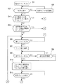
先ず、図23に示す如く、ステップS1で電源投入、即ち電源スイッチをONし、洗浄水が満水か否かの判断を行う(ステップS2)。そして、前述した洗浄水タンク14内の水位が満水でない場合(NO)、洗浄水タンク14への給湯運転を行う(ステップS3)。
【0083】
ここで、給湯運転を説明すると、前記ブースタータンク8にて約80℃に加熱されたすすぎ水を、すすぎ水ポンプによって、前記上下回転すすぎノズル24A、24B、及びカーテンすすぎノズル62から噴射供給する。
【0084】
上下回転すすぎノズル24A、24Bから噴射されたすすぎ水は、洗浄エリア3Aの各部位にあたり、又は直接的に洗浄水タンク14に導入され、カーテンすすぎノズル62から噴射されたすすぎ水は、前述した如く、搬出側カーテン30の洗浄エリア3A側にあたり洗浄水タンク14内に導入される。
【0085】
そして、洗浄水タンク14内に所定水位給湯された後(YES)、図示しないが洗剤などを投入して洗浄水として用いる事のできる状態とし、前回の電源OFF時に洗浄サイクル運転中であったか否か判断する(ステップS4)。
【0086】
ここで、前回の電源遮断時、即ち電源OFF時が洗浄サイクル運転中でない場合(NO)、前回の電源OFF時にラック5の搬出運転中であったか否か判断する(ステップS5)。
【0087】
前回の電源OFF時がラック5の搬出運転中でなかった場合(NO)、搬入スイッチ31AがONであるか否かの判断を行う(ステップS6)。ここで、搬入スイッチ31AがONでない場合(NO)、使用者がまだ被洗浄物4を収納したラック5を洗浄しようとしていないため、搬入スイッチ31AがONになるまで待つ。
【0088】
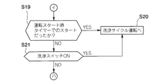
そして、使用者が手でラック5を押し込み、搬入スイッチ31AがONになった場合(YES)、図20に示す状態となっており、ラック搬入運転を開始する(ステップS7)。
【0089】
このラック搬入運転に際しては、フルサイズラック5A、ハーフサイズラック5Bのどちらを用いるか、又はどの組み合わせで用いるかにより異なる。
【0090】
先ず、フルサイズラック5Aを入れた場合、図5に示す如く、コンベア装置20の搬入側が上方に傾斜し、フルサイズラック5Aの底面に前記第一及び第二爪45A、45Bが引っかかり、フルサイズラック5Aを洗浄エリア3Aに導入する。
【0091】
この際、フルサイズラック5Aによって、洗浄エリア3Aの洗浄スイッチ33AがONしたか否か判断し(ステップS8)、洗浄スイッチ33AがONした場合(YES)、ラック搬入運転を停止、即ちコンベア装置20を停止して、洗浄サイクル運転を行う。そして、ラック送り機構は搬出側へ移行させる(ステップS10)。
【0092】
次に、ハーフサイズラック5Bを一つ入れた場合、前述同様、コンベア装置20の搬入側が上方に傾斜し、図7に示す如く、ハーフサイズラック一つの場合、第二爪45Bの引っかかりが解除される位置まできても、洗浄スイッチ部33の当接部36に当接しないため、洗浄スイッチ33AはONしない。
【0093】
従って、この場合には、前記搬入スイッチ31AがONしてから設定時間(本実施形態では15秒)が経過したか否かをタイマーにて判断し(ステップS9)、15秒経過していなければ(NO)、ステップS8に戻り、設定時間である15秒経過した場合(YES)、ラック搬入運転を停止、即ちコンベア装置20を停止して、洗浄サイクル運転を行う。そして、ラック送り機構は搬出側へ移行させる(ステップS10)。
【0094】
尚、ハーフサイズラック5Bを二つ入れた場合は、フルサイズラック5Aを一つ入れた場合と同様となる。即ち、最初に入れたハーフサイズラック5Bは、上述と同様に第二爪45Bの引っかかりが解除された位置で停止するが、次に入れられたハーフサイズラック5Bにて搬出側に押されるため、洗浄スイッチ33AをONする事となる。
【0095】
次に、最初にハーフサイズラック5Bを入れ、次いでフルサイズラック5Aを入れた場合、図12に示す如く、最初のハーフサイズラック5Bが洗浄スイッチ33AをONするため、洗浄サイクル運転に移行する(ステップS10)。
【0096】
ここで、図21に示す洗浄サイクル運転を説明する。
洗浄サイクル運転は、前記洗浄水タンク14内の洗浄水を洗浄ポンプ15にて上下回転洗浄ノズル23A、23Bに供給し、ラック5内に収納された被洗浄物4に噴射する。そして、この洗浄水の噴射を所定時間行った後、洗浄ポンプ15を停止し、すすぎポンプ16を運転する。すすぎポンプ16の運転により、ブースタータンク8内のすすぎ水を上下回転すすぎノズル24A、24Bに供給し、被洗浄物4のすすぎを所定時間行う。
【0097】
この時、前記搬出側カーテン30の洗浄エリア3A側にも洗浄水が付着しているので、カーテンすすぎノズル62にもすすぎ水を供給し、搬出側カーテン30の洗浄エリア3A側に付着した洗浄水の残水をすすぐ。
【0098】
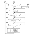
そして、この洗浄サイクル運転が終了したか否かの判断を行い(ステップS11)、即ち洗浄、すすぎの時間が終了したか否か判断し、洗浄サイクル運転が終了していれば、ラック検出スイッチ32AがOFFであるか否かの判断を行う(ステップS12)。
【0099】
次に、ラック検出スイッチ32AがOFFでない場合(NO)、前記ソレノイド56に通電し(ステップS13)、前記第二爪45Bがフルサイズラック5Aと引っかからない様に倒し、ラック搬出運転に移行する(ステップS14)。
【0100】
ここで、ステップS12でラック検出スイッチ32AがOFFで無い場合(NO)は、前述した最初にハーフサイズラック5B、次いでフルサイズラック5Aを入れた場合で、このまま洗浄サイクル運転を終了してしまうと、二つ目に導入されたフルサイズラック5Aの後半部分が洗浄されない事となってしまう。
【0101】
このため、最初のハーフサイズラック5B及び次のフルサイズラック5Aの前半部分を洗浄した後、ステップS13にてソレノイド56に通電し第二爪45Bを倒してフルサイズラック5Aを搬出せず、前のハーフサイズラック5Bのみを搬出する。
【0102】
この様に、最初にハーフサイズラック5B、次にフルサイズラック5Aを入れた場合、最初のハーフサイズラック5Bを搬出した後、前半部分のみ洗浄の終了したフルサイズラック5Aを再び洗浄する。
【0103】
従って、異なるサイズのラック5(本実施形態では、フルサイズラック5A、ハーフサイズラック5Bの2種類)を用いても、確実に洗浄サイクル運転を行う事ができる。
【0104】
次に、図22に示すラック搬出運転について説明する。
上述した様な洗浄サイクル運転が終了すると、ラック5を搬出側へ送るラック搬出運転(ステップS14)を行う。このラック搬出運転は、図6及び図9に示す如く、コンベア装置20の搬出側が上方に傾斜し、ラック5の底面に第二乃至第四爪45B、45C、45Dのうち、少なくとも二箇所以上の爪45が引っかかり、ラック5を搬出方向へ導く。
【0105】
ここで、ハーフサイズラック5B、フルサイズラック5Aの順で入っていた場合、第二爪45Bは倒れ、第三、第四爪45C、45Dのみで
ハーフサイズラック5Bのみを搬出する。
【0106】
この際、搬出されるラック5は一度搬出スイッチ34AをONし、次いでラック5が搬出スイッチ部34を通過すると、搬出スイッチ34AをOFFする。また、ハーフラック5Bが2個の場合、最初の1個が搬出された時に、一旦、搬出スイッチ34AがOFFされる。
【0107】
先ず、この搬出スイッチ34AがONとなったか否かを判断し(ステップS15)、搬出スイッチ34AがONとなった場合(YES)、タイマーによる計測時間が、設定時間である10秒経過したか否かの判断を行う(ステップS16)。
【0108】
そして、ステップS16で10秒経過した後(YES)、前記搬出スイッチ34AがOFFであるか否かの判断を行い(ステップS17)、搬出スイッチ34AがOFFであれば(YES)、ラック搬出運転を停止し、ステップS13でソレノイド56に通電していれば、ソレノイド56への通電も停止する。そして、ラック送り機構は搬入側へ移行させる(ステップS18)。
【0109】
この様に、搬出口28近傍に設けられた搬出スイッチ34Aにてタイマーをスタートし、タイマーの計測が終了した時に搬出運転を完了する様に制御する事と、搬出スイッチ34Aの組み合わせで、ラック5が確実に搬出されない限り、次の洗浄サイクル運転に移行せず、洗浄済みラック5への洗浄水の飛散を防止する事ができる。
【0110】
従って、洗浄した後の被洗浄物4を、次の洗浄サイクル運転時に生じる洗浄水で汚してしまう事を防止でき、被洗浄物4を衛生的に扱う事ができるものである。
【0111】
そして、ステップS6に戻り、次のラック5が搬入されて、搬入スイッチ31AがONとなるまで待つ。
【0112】
尚、本実施形態では、コンベア装置20の搬送速度は4m/分であり、この搬送速度から、各設定時間を決定している。
【0113】
次いで、ステップS4にて前回の電源OFF時が洗浄サイクル運転中であった場合(YES)、図25のフローチャートに移行する。
【0114】
先ず、フルサイズラック5Aが洗浄スイッチ33Aで運転スタートし、ハーフサイズラック5Bがタイマーで運転スタートするため、運転スタート時タイマーでのスタートであったか否かを判断する(ステップS19)。
【0115】
ステップS19にて、タイマーで運転スタートしていた場合(YES)、そのまま洗浄サイクル運転へ移行し(ステップS20)、タイマーで運転スタートしたのでない場合(NO)、洗浄スイッチ33AがONであるか否かの判断に移行する(ステップS21)。
【0116】
そして、ステップS21で洗浄スイッチ33AがONであれば(YES)、ステップS20へ移行し、洗浄サイクル運転を行い、洗浄スイッチ33AがONでなければ(NO)、ステップS6の搬入スイッチ31AがONか否かの判断へ移行する。
【0117】
この前回電源OFF時が洗浄サイクル運転中で、且つタイマースタートでなくて洗浄スイッチ33AもONでない場合は、洗浄サイクル運転中に電源を切って、使用者が前記洗浄室扉13を開放し、洗浄室3内のラック5を取り出してしまったときに生じる。
【0118】
また、ステップS5にて前回の電源OFF時がラック搬出運転中であった場合(YES)、図26のフローチャートに移行する。
【0119】
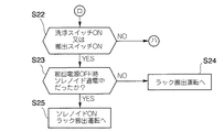
ここでは、洗浄スイッチ33A又は搬出スイッチ34AがONであるか否かの判断を行う(ステップS22)。そして、洗浄スイッチ33A又は搬出スイッチ34AのいずれもONでない場合(NO)、前述同様、使用者が前記洗浄室扉13を開放し、洗浄室3内のラック5を取り出してしまっているので、ステップS6の搬入スイッチ31AがONか否かの判断へ移行する。
【0120】
また、ステップS22で洗浄スイッチ33A又は搬出スイッチ34AのいずれかがONである場合(YES)、前回の電源OFF時にソレノイド56が通電中であったか否かの判断を行う(ステップS23)。
【0121】
ステップS23で前回の電源OFF時、ソレノイド56へ通電していなければ(NO)、フルサイズラック5Aが一つ、又はハーフサイズラック5B一つ乃至二つであるため、そのままラック搬出運転へ移行する(ステップS24)。
【0122】
また、前回の電源OFF時、ソレノイド56へ通電していた場合(YES)、最初にハーフサイズラック5B、次にフルサイズラック5Aが入っているので、ソレノイド56をONし、ラック搬出運転を行う(ステップS25)。
【0123】
以上の如く、洗浄サイクル運転中に電源が遮断された場合、再度最初から洗浄サイクル運転を行い、電源遮断時の洗浄サイクル運転が、タイマーにて運転開始されていた場合も、再度最初から洗浄サイクル運転を行う。
【0124】
従って、被洗浄物4を確実に洗浄することができ、被洗浄物4を衛生的に扱う事ができる。
【0125】
また、洗浄サイクル運転中に電源遮断され、タイマーにて運転開始されていなかったと共に、電源投入後、洗浄スイッチ33Aが入っていなければ、洗浄室3のラック5は取り出されているため、最初のラック搬入運転から再開する。
【0126】
更に、ラック搬出運転中に電源が遮断され、電源投入後、前記洗浄スイッチ33A及び搬出スイッチ34Aのいずれもが切れている場合、ラック5は洗浄室3内から取り出されているため、最初のラック搬入運転から再開する。
【0127】
更にまた、ラック搬出運転中に電源が遮断され、電源投入後、前記洗浄スイッチ33A或いは搬出スイッチ34Aのいずれかが入っている場合、ラック5は洗浄室3内に残っているため、ラック搬出運転を行う。
【0128】
この様に、ラック5が検出されない場合、電源遮断時からの運転を行わず、最初のラック搬入運転から行い、ラック5が検出された場合、その運転を再度行う事により、無駄な運転を行う事はなくなる。
【0129】
【発明の効果】
本発明は、以上詳述した如く、本発明によると、コンベア装置を傾斜装置によって、ラックの搬入時には搬入側が上方となるように傾斜させ、ラックの搬出時には搬入側のラックの搬入を防止するよう爪が搬入側のラックに引っかからない状態に搬入側が下方となるように傾斜させるようにしている。即ち、ラック搬出時には搬入側が下方となり、コンベア装置が搬入側のラックを搬入してしまうことを防止できる。従って、洗浄室に被洗浄物が搬入されている場合、その被洗浄物の洗浄、搬出が行われるまで次の洗浄サイクル運転に移行する事はないため、確実に被洗浄物の洗浄を行う事ができる。
【図面の簡単な説明】
【図1】本発明を具備する食器洗浄機の正面図である。
【図2】食器洗浄機の断面図である。
【図3】ラック搬入側の食器洗浄機の斜視図である。
【図4】ラックを搬出入するコンベア装置の分解斜視図である。
【図5】フルサイズラック搬入時のコンベア装置の正面図である。
【図6】フルサイズラック洗浄時のコンベア装置の正面図である。
【図7】ハーフサイズラック搬入時のコンベア装置の正面図である。
【図8】2つのハーフサイズラック搬入時におけるコンベア装置の正面図である。
【図9】2つのハーフサイズラック搬出時におけるコンベア装置の正面図である。
【図10】コンベア装置の側断面図である。
【図11】コンベア装置の揺動機構の拡大図である。
【図12】ハーフサイズラックの後にフルサイズラックを搬入した時のコンベア装置の正面図である。
【図13】ラック搬出側の食器洗浄機の斜視図である。
【図14】搬出側カーテンの斜視図である。
【図15】食器洗浄機搬出側の拡大図である。
【図16】カーテン洗浄装置の斜視図である。
【図17】扉安全スイッチの平面図である。
【図18】扉安全スイッチの正面図である。
【図19】オーバーフロー構造を示す要部拡大図である。
【図20】ラック搬入時の動作説明図である。
【図21】ラック洗浄時の動作説明図である。
【図22】ラック搬出時の動作説明図である。
【図23】本発明の食器洗浄機の制御を示すフローチャートである。
【図24】図23の続きを示すフローチャートである。
【図25】前回電源OFF時に洗浄サイクル運転中であった場合のフローチャートである。
【図26】前回電源OFF時にラック搬出運転中であった場合のフローチャートである。
【符号の説明】
1 食器洗浄機
3 洗浄室
4 被洗浄室
5 ラック
20 コンベア装置
21 傾斜装置
27 搬入口
28 搬出口[0001]
BACKGROUND OF THE INVENTION
The present invention relates to a dishwasher for cleaning an object to be cleaned such as tableware.
[0002]
[Prior art]
Conventionally, as shown in Japanese Utility Model Publication No. 1-35705 (A47L15 / 42), this type of tableware washing machine stores tableware in a rack, and carries the rack into a washing room hood via a conveyor. A structure for cleaning dishes by spraying cleaning liquid from a cleaning liquid spray pipe is disclosed.
[0003]
In general, a dishwasher that cleans such objects to be cleaned while transporting them from the carry-in side to the carry-out side by means of a conveyor, etc. is called a conveyor type, and by pushing a rack containing the items to be washed from the carry-in entrance, The conveyer conveys to the unloading side and cleans it with a cleaning liquid that is constantly sprayed at the conveying stage. Such a conveyor type dishwasher is easy to use because it only pushes the rack.
[0004]
[Problems to be solved by the invention]
The conveyor type dishwasher as described above has a problem in that the rinse water is discharged, and thus the rinse water is wasted when the washing is started.
[0005]
The present invention has been made in view of the above-described problems, and provides a dishwasher aimed at reducing the amount of water consumption with the convenience of a conveyor type.
[0006]
[Means for Solving the Problems]
As a means to achieve the above purpose,The dishwasher of the present invention isA cleaning room for cleaning objects such as dishes;Formed on one side of this cleaning chamberA carry-in port for carrying a rack storing the objects to be washed into the washing room;Formed on the other side of this cleaning chamberA carry-out port for carrying out the rack storing the objects to be cleaned from the cleaning chamber;The claw is arranged in the longitudinal direction from the carry-in port to the carry-out port, and the claw is not caught by the rack when moving to the carry-in side of the rack, and the claw is caught by the rack when moving to the carry-out side. A conveyor device for transporting the rack in the unloading direction; and when the rack is loaded, the conveyor device is inclined so that the loading side is upward, and when the rack is unloaded, the claw is disposed on the loading side to prevent loading of the loading-side rack. Inclining device for inclining the conveyor device so that the loading side faces downward so that the rack is not caught by the rackIt is characterized by comprising.
Also,The dishwasher of the present invention includes a cleaning chamber for cleaning objects to be cleaned such as tableware, a carry-in entrance for carrying a rack formed on one side of the cleaning chamber and storing the objects to be cleaned into the cleaning chamber, and the cleaning chamber. And a rod having a claw arranged in a longitudinal direction from the carry-in port to the carry-out port, and a swingable holding of the rod. When the rod is moved to the carry-in side of the rack, the claw falls to the carry-out side and slides into the lower surface of the rack without being caught by the rack, and the rod is moved to the carry-out side. An oscillating device that oscillates the conveyor device so that the claw catches on the lower surface of the rack and carries the rack in the carry-out direction, and the conveyor connected to the oscillating device when the rack is loaded The conveyor device is connected to the swing device so that the claw is not caught by the loading-side rack so that the loading-side rack is prevented from being loaded when the rack is unloaded. And an inclining device that inclines so that the carry-in side is downward.
[0007]
In this way, since the conveyor device can be tilted to both the carry-in side and the carry-out side, the conveyor device is tilted so that the carry-in side is upward when loading the rack, and the carry-in side is lowered when the rack is unloaded. Can be prevented.
[0012]
DETAILED DESCRIPTION OF THE INVENTION
Hereinafter, embodiments of the present invention will be described with reference to the drawings.
FIG. 1 is a front view of a dishwasher equipped with the present invention, FIG. 2 is a sectional view of the dishwasher, FIG. 3 is a perspective view of a dishwasher on the rack carry-in side, and FIG. 4 is a conveyor device for carrying in and out the rack. FIG. 5 is a front view of the conveyor device when carrying a full-size rack, FIG. 6 is a front view of the conveyor device when washing a full-size rack, and FIG. 7 is a front view of the conveyor device when carrying a half-size rack. 8 is a front view of the conveyor device when two half-size racks are loaded, FIG. 9 is a front view of the conveyor device when two half-size racks are unloaded, FIG. 10 is a side sectional view of the conveyor device, and FIG. FIG. 12 is a front view of the conveyor device when a full size rack is loaded after a half size rack, FIG. 13 is a perspective view of a dishwasher on the rack carry-out side, and FIG. 14 is a carry-out
[0013]
In FIG. 1 and FIG. 2,
[0014]
Further, on the right side of the
[0015]
Further, a
[0016]
The lower part of the
[0017]
Furthermore, the
[0018]
Further, the
[0019]
Next, the internal structure of the
A
[0020]
A
[0021]
The
[0022]
Further, as shown in FIG. 1, a
[0023]
Next, the internal structure of the
In the
[0024]
As described above, since the nozzles used for cleaning and rinsing are rotary, and a pair of upper and lower nozzles are provided, it is possible to clean the entire object to be cleaned during cleaning and rinsing, and the object to be cleaned can be handled in a sanitary manner.
[0025]
In addition, when the upper
[0026]
In the present embodiment, the
[0027]
Further, the
[0028]
Then, in order to supply the cleaning water in the cleaning
[0029]
In addition, a heating device such as an electric heater is provided in the cleaning
[0030]
Further, in order to supply the rinsing water in the
[0031]
Further, as shown in FIG. 3, a carry-in
[0032]
A carry-in
[0033]
These carry-in
[0034]
Further, in the
[0035]
Each of these
[0036]
Therefore, when the
[0037]
Further, a
[0038]
Next, the
[0039]
The
[0040]
The
[0041]
In this embodiment, a total of eight of these pairs of first to
[0042]
That is, the
[0043]
And these 1st thru | or 4th nail | claw 45A, 45B, 45C, 45D is tilted downward in the rack carrying-in direction, and is attached so that rotation is possible, 1st thru | or 4th nail | claw 45A, 45B, 45C, A
[0044]
Accordingly, by swinging the
[0045]
In this way, the
[0046]
Further, since the cleaning cycle operation is performed when the rack is carried into a predetermined position in the
[0047]
Next, the
[0048]
The
[0049]
Accordingly, by driving the
[0050]
In the present embodiment, the second connecting
[0051]
Next, the tilting
[0052]
Further, a downwardly
[0053]
The
[0054]
However, when the half-
[0055]
Therefore, in this case, as shown in FIG. 12, the
[0056]
This mechanism pushes the lower inclined end of the
[0057]
Therefore, if there is a
[0058]
Next, the carry-out
[0059]
The carry-out
[0060]
Further, at least the
[0061]
Then, the carry-out
[0062]
Specifically, the height of the state in which the article to be cleaned 4 is placed on the
[0063]
With the above-described configuration, the
[0064]
In addition, when the carry-out
[0065]
Further, a curtain cleaning device, that is, a
[0066]
The
[0067]
In this way, since the
[0068]
Next, the
[0069]
The
[0070]
When the normal
[0071]
Further, when problems such as cleaning, maintenance, clogging of the
[0072]
As described above, since the cleaning cycle operation is disabled when the cleaning
[0073]
Furthermore, even if the cleaning
[0074]
Therefore, it is possible to prevent the surroundings of the
[0075]
Next, the
Although not shown, a filter for removing large residue and a water level detection switch for detecting the water level of the cleaning water are provided at the upper part of the cleaning
[0076]
In particular, in the case of the
[0077]
Therefore, an
[0078]
The
[0079]
By configuring as described above, normally, the water level indicated by the two-dot chain line shown in FIG. 19 does not rise, and even if the
[0080]
Therefore, even if the
[0081]
With the above configuration, the control of the
[0082]
First, as shown in FIG. 23, in step S1, the power is turned on, that is, the power switch is turned on, and it is determined whether or not the cleaning water is full (step S2). And when the water level in the
[0083]
Here, the hot water supply operation will be described. Rinsing water heated to about 80 ° C. in the
[0084]
The rinse water sprayed from the vertically rotating rinse
[0085]
Then, after a predetermined level of hot water has been supplied into the cleaning water tank 14 (YES), it is set in a state where it can be used as cleaning water by introducing a detergent (not shown). Judgment is made (step S4).
[0086]
Here, when the power is cut off last time, that is, when the power is turned off, the cleaning cycle operation is not in progress (NO), it is determined whether or not the
[0087]
If the
[0088]
When the user pushes the
[0089]
In this rack carrying-in operation, it differs depending on which of the
[0090]
First, when the
[0091]
At this time, it is determined whether or not the cleaning
[0092]
Next, when one half-
[0093]
Therefore, in this case, it is determined by a timer whether or not a set time (15 seconds in the present embodiment) has elapsed since the carry-in
[0094]
In addition, when two
[0095]
Next, when the
[0096]
Here, the cleaning cycle operation shown in FIG. 21 will be described.
In the cleaning cycle operation, the cleaning water in the cleaning
[0097]
At this time, since the washing water is also attached to the
[0098]
Then, it is determined whether or not the cleaning cycle operation has been completed (step S11), that is, whether or not the cleaning and rinsing time has ended. If the cleaning cycle operation has been completed, the
[0099]
Next, when the
[0100]
Here, when the
[0101]
For this reason, after washing the first half-
[0102]
As described above, when the half-
[0103]
Accordingly, even if
[0104]
Next, the rack carry-out operation shown in FIG. 22 will be described.
When the cleaning cycle operation as described above is completed, a rack carry-out operation (step S14) for sending the
[0105]
Here, when the
Only the half-
[0106]
At this time, the
[0107]
First, it is determined whether or not the carry-out
[0108]
Then, after 10 seconds have elapsed in step S16 (YES), it is determined whether or not the carry-out
[0109]
In this way, the
[0110]
Therefore, it is possible to prevent the object 4 to be cleaned from being contaminated with the cleaning water generated during the next cleaning cycle operation, and the object 4 to be cleaned can be handled in a sanitary manner.
[0111]
Then, the process returns to step S6 and waits until the
[0112]
In the present embodiment, the conveying speed of the
[0113]
Next, in step S4, when the previous power-off was during the cleaning cycle operation (YES), the process proceeds to the flowchart of FIG.
[0114]
First, since the full-
[0115]
In step S19, if the operation has been started with a timer (YES), the process proceeds to the cleaning cycle operation (step S20). If the operation has not been started with the timer (NO), whether or not the cleaning
[0116]
If the
[0117]
If the previous power-off was during the cleaning cycle operation and the timer was not started and the
[0118]
In step S5, when the previous power-off time was during the rack carry-out operation (YES), the process proceeds to the flowchart of FIG.
[0119]
Here, it is determined whether or not the cleaning
[0120]
If either the
[0121]
If the
[0122]
If the
[0123]
As described above, when the power supply is cut off during the cleaning cycle operation, the cleaning cycle operation is performed again from the beginning, and even when the cleaning cycle operation at the time of the power interruption is started by the timer, the cleaning cycle is started again from the beginning. Do the driving.
[0124]
Accordingly, the object to be cleaned 4 can be reliably cleaned, and the object to be cleaned 4 can be handled in a sanitary manner.
[0125]
In addition, if the power is cut off during the cleaning cycle operation and the operation has not been started by the timer and the
[0126]
Further, when the power is cut off during the rack unloading operation and both the
[0127]
Furthermore, when the power is cut off during the rack unloading operation and either the
[0128]
As described above, when the
[0129]
【The invention's effect】
The present invention, as detailed above,According to the present invention, the conveyor device is tilted by the tilting device so that the loading side is upward when the rack is loaded, and the claw is not caught on the loading side rack so as to prevent the loading side rack from being loaded when the rack is unloaded. It is made to incline so that the carrying-in side may become downward. That is,When the rack is carried out, the carry-in side becomes the lower side, and the conveyor device can be prevented from carrying the carry-in side rack. Therefore, if an object to be cleaned is carried into the cleaning chamber, the cleaning object will not be transferred to the next cleaning cycle until the object to be cleaned is washed and unloaded. Can do.
[Brief description of the drawings]
FIG. 1 is a front view of a dishwasher equipped with the present invention.
FIG. 2 is a cross-sectional view of a dishwasher.
FIG. 3 is a perspective view of a dishwasher on the rack carry-in side.
FIG. 4 is an exploded perspective view of a conveyor device for carrying in and out a rack.
FIG. 5 is a front view of the conveyor device when carrying a full-size rack.
FIG. 6 is a front view of the conveyor device during full-size rack cleaning.
FIG. 7 is a front view of the conveyor device when carrying a half-size rack.
FIG. 8 is a front view of the conveyor device when two half-size racks are loaded.
FIG. 9 is a front view of the conveyor device when carrying out two half-size racks.
FIG. 10 is a side sectional view of the conveyor device.
FIG. 11 is an enlarged view of a swing mechanism of the conveyor device.
FIG. 12 is a front view of the conveyor device when a full-size rack is loaded after a half-size rack.
FIG. 13 is a perspective view of a dishwasher on the rack carry-out side.
FIG. 14 is a perspective view of a carry-out curtain.
FIG. 15 is an enlarged view of the dishwasher carry-out side.
FIG. 16 is a perspective view of the curtain cleaning device.
FIG. 17 is a plan view of a door safety switch.
FIG. 18 is a front view of a door safety switch.
FIG. 19 is an enlarged view of a main part showing an overflow structure.
FIG. 20 is an operation explanatory diagram when a rack is carried in.
FIG. 21 is an explanatory diagram of an operation during rack cleaning.
FIG. 22 is an operation explanatory diagram when carrying out the rack;
FIG. 23 is a flowchart showing control of the dishwasher of the present invention.
FIG. 24 is a flowchart showing a continuation of FIG.
FIG. 25 is a flowchart when the cleaning cycle is being operated when the power is turned off last time.
FIG. 26 is a flowchart when the rack unloading operation was being performed when the power was turned off last time.
[Explanation of symbols]
1 dishwasher
3 Cleaning room
4 Room to be cleaned
5 racks
20 Conveyor device
21 Tilting device
27 Carriage entrance
28 Unloading
Claims (2)
Priority Applications (1)
| Application Number | Priority Date | Filing Date | Title |
|---|---|---|---|
| JP29297899A JP4222697B2 (en) | 1999-10-14 | 1999-10-14 | Dishwasher |
Applications Claiming Priority (1)
| Application Number | Priority Date | Filing Date | Title |
|---|---|---|---|
| JP29297899A JP4222697B2 (en) | 1999-10-14 | 1999-10-14 | Dishwasher |
Publications (2)
| Publication Number | Publication Date |
|---|---|
| JP2001112687A JP2001112687A (en) | 2001-04-24 |
| JP4222697B2 true JP4222697B2 (en) | 2009-02-12 |
Family
ID=17788897
Family Applications (1)
| Application Number | Title | Priority Date | Filing Date |
|---|---|---|---|
| JP29297899A Expired - Fee Related JP4222697B2 (en) | 1999-10-14 | 1999-10-14 | Dishwasher |
Country Status (1)
| Country | Link |
|---|---|
| JP (1) | JP4222697B2 (en) |
Families Citing this family (1)
| Publication number | Priority date | Publication date | Assignee | Title |
|---|---|---|---|---|
| KR101134491B1 (en) | 2009-07-10 | 2012-04-13 | 채승병 | Dish washer |
-
1999
- 1999-10-14 JP JP29297899A patent/JP4222697B2/en not_active Expired - Fee Related
Also Published As
| Publication number | Publication date |
|---|---|
| JP2001112687A (en) | 2001-04-24 |
Similar Documents
| Publication | Publication Date | Title |
|---|---|---|
| CN203252618U (en) | Industrial dish washing machine | |
| US20090320883A1 (en) | Dishwasher with a pivoting apparatus | |
| CN117222351A (en) | Dishwasher in the form of a counter module for a counter system | |
| US20240188786A1 (en) | Dishwasher, in particular in the shape of a counter module for a counter system | |
| JP4222698B2 (en) | Dishwasher | |
| JP4222697B2 (en) | Dishwasher | |
| JP4330224B2 (en) | Dishwasher | |
| JP4330225B2 (en) | Dishwasher | |
| JP2001112691A (en) | Dishwasher | |
| JP2001112701A (en) | Dishwasher | |
| JP2001112692A (en) | Dishwasher | |
| JP2001112689A (en) | Dishwasher | |
| JPH0386136A (en) | Dish washer | |
| JP2022122531A (en) | washing machine and washing system | |
| JP2932272B1 (en) | Bottle cleaning device and bottle holding basket used for it | |
| JPH10328627A (en) | Rice cooker cleaning equipment | |
| JP2541389Y2 (en) | Dishwashing equipment | |
| JP7489931B2 (en) | Cleaning machines and systems | |
| JP7630275B2 (en) | Cleaning System | |
| JPH08289868A (en) | Dish washer | |
| JP7288106B2 (en) | Cleaning method and cleaning equipment | |
| JPH06245890A (en) | Batchwise conveyor type washer | |
| JPH11192197A (en) | Dishwasher / dryer and rack used for it | |
| JP2024178506A (en) | Dishwashing Equipment | |
| JPH03212252A (en) | Dish washer |
Legal Events
| Date | Code | Title | Description |
|---|---|---|---|
| A621 | Written request for application examination |
Free format text: JAPANESE INTERMEDIATE CODE: A621 Effective date: 20060908 |
|
| A977 | Report on retrieval |
Free format text: JAPANESE INTERMEDIATE CODE: A971007 Effective date: 20080507 |
|
| A131 | Notification of reasons for refusal |
Free format text: JAPANESE INTERMEDIATE CODE: A131 Effective date: 20080513 |
|
| A521 | Written amendment |
Free format text: JAPANESE INTERMEDIATE CODE: A523 Effective date: 20080626 |
|
| TRDD | Decision of grant or rejection written | ||
| A01 | Written decision to grant a patent or to grant a registration (utility model) |
Free format text: JAPANESE INTERMEDIATE CODE: A01 Effective date: 20081021 |
|
| A01 | Written decision to grant a patent or to grant a registration (utility model) |
Free format text: JAPANESE INTERMEDIATE CODE: A01 |
|
| A61 | First payment of annual fees (during grant procedure) |
Free format text: JAPANESE INTERMEDIATE CODE: A61 Effective date: 20081118 |
|
| FPAY | Renewal fee payment (event date is renewal date of database) |
Free format text: PAYMENT UNTIL: 20111128 Year of fee payment: 3 |
|
| LAPS | Cancellation because of no payment of annual fees |