JP4222684B2 - Locking mechanism for sliding doors - Google Patents
Locking mechanism for sliding doors Download PDFInfo
- Publication number
- JP4222684B2 JP4222684B2 JP12721499A JP12721499A JP4222684B2 JP 4222684 B2 JP4222684 B2 JP 4222684B2 JP 12721499 A JP12721499 A JP 12721499A JP 12721499 A JP12721499 A JP 12721499A JP 4222684 B2 JP4222684 B2 JP 4222684B2
- Authority
- JP
- Japan
- Prior art keywords
- hook
- control lever
- slider
- stopper
- support shaft
- Prior art date
- Legal status (The legal status is an assumption and is not a legal conclusion. Google has not performed a legal analysis and makes no representation as to the accuracy of the status listed.)
- Expired - Fee Related
Links
- 239000000523 sample Substances 0.000 description 10
- 238000010586 diagram Methods 0.000 description 5
- 230000000694 effects Effects 0.000 description 2
- 230000006835 compression Effects 0.000 description 1
- 238000007906 compression Methods 0.000 description 1
- 239000000463 material Substances 0.000 description 1
- 230000013011 mating Effects 0.000 description 1
- 230000002441 reversible effect Effects 0.000 description 1
- 238000003466 welding Methods 0.000 description 1
Images


Landscapes
- Lock And Its Accessories (AREA)
Description
【0001】
【発明の属する技術分野】
この発明は、引戸用施錠機構に係り、特に、施錠時カマを錠箱内に押し戻すことを防止できる新規な引戸用施錠機構に関する。
【0002】
【従来の技術】
引戸用施錠機構は、通常、カマと称する鈎状の部材を一方の引戸に装着された錠箱のフロント板から振出し、他方の引戸のストライク板に引っ掛けるように構成されている。
【0003】
上記カマは、簡単な構造の引戸用施錠機構においては、室内側から操作される摘みに連動して上下動するスライダによって錠箱のフロント板から出し入れされる。
【0004】
【発明が解決しようとする課題】
しかしながら、一般に機構は可逆的であるから、例えばこの引戸用施錠機構の摘みを施錠方向に駆動してカマをフロント板から振出し、カマを相手方の引戸のストライク板に引っ掛けたとしても、何等かの手段により逆にカマを錠箱内に回し戻せば、このカマの動きに連動してスライダが解錠方向に戻り、結果として解錠されてしまい、錠前として役に立たない場合がある。
【0005】
この発明は、一旦振出したカマを外側からは錠箱内に戻すことができない引戸用施錠機構を提供し、もって引戸用施錠機構の安全性を向上させることを目的としている。
【0006】
【課題を解決するための手段】
上記の目的を達成するため、この発明は、引戸に装着された錠箱内において、中央部をフロント板の近傍における水平な第一支軸の回りを回動自在に支承され、一端に、フロント板から振り出て他方の引戸のストライク板と係合する鈎部を形成したカマと、このカマと一部重合する位置関係で上下方向に移動可能に案内されたスライダとを有し、カマの他端部及びスライダの何れか一方に突設された係合ピン、及び他方に開口した案内長孔とを係合させて、スライダの上下方向の移動によってカマをフロント板から出し入れするようにしたものにおいて、カマに関しスライダとは反対側にフロント板に垂直な前後方向に延在する制御レバーを配設し、この制御レバーの中央部を第一支軸と平行な第二支軸の回りを回動可能に支承すると共に、制御レバーのフロント板に近い方の前部をカマに近接する方向に付勢し、一方、スライダの制御レバーに最も近い部分の後方にストッパーを、カマの外縁に第一係合部を夫々形成し、他方、制御レバー前端のカマに対向する部分に第二係合部を、後端のストッパーの移動軌跡と交差する部分に係止段部を夫々形成し、カマの施錠方向の回動時その外縁が制御レバーの前端部を付勢力に抗してカマから離間する方向に押圧するようにその形状を設定し、もって前傾した制御レバーの後方をストッパーが通過できるようにし、また、施錠時、上下方向において第一支軸及び第二支軸の間にある第二係合部に第一係合部を前方から係合可能に臨ませると共に、スライダのストッパーを制御レバーの係止段部に係合させるようにし、以て、カマを錠箱内に押込もうとする力を、上記第一及び第二係合部の係合及び制御レバーを介してストッパーに衝止させるようにしたことを特徴とする。
【0007】
【実施例】
以下、この発明の一実施例を図面を参照して説明する。
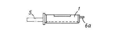
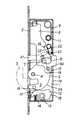
図1及び図2において符号1は錠箱を示し、この錠箱1は図示しない引戸の一方の框に装着される。
【0008】
この錠箱1内には、カマ2がフロント板3の近傍に設けられた水平な第一支軸4の回りを回動可能に支承されている。
【0009】
このカマ2の一端(図2で下端)には、フロント板3の開口から振り出て他方の引戸(図示せず)のストライク板と係合する鈎部5が形成されている。
【0010】
ちなみに、このカマ2は、プレスにより図2に示すような形状に打ち抜いた板材を重合し、例えばスポット溶接により一体に結合する。
【0011】
このカマ2の図2における手前側に、カマ2と一部重合する位置関係でスライダ6が配設され、上下方向に移動可能に案内されている。
【0012】
このスライダ6の室内側の後端縁下端部には係合片6aが一体に突設されており、この係合片6aは錠箱1の背面に形成された縦長いスリット1aを挿通して錠箱外に突出している。
【0013】
そして、上記スライダ6は、係合片6a、及び室内側に設けられた図示しない操作摘みを介して、人の手指により上下方向に駆動される。
【0014】
一方、上記カマ2の他端には係合ピン7が図2で手前側に突設されており、この係合ピン7に対応して、スライダの下端部には、フロント板に垂直な前後方向(図2で左右方向)に長い案内長孔8が開口している。
【0015】
そして、カマ2及びスライダ6は、これら傾向ピン7の係合により相互に一体的に連係され、スライダが下降すると(図示せず)、カマ2が第一支軸4の回りを時計方向に回動し、その鈎部5がフロント板から振り出て(図2鎖線参照)相手方の引戸のストライク板と係合する。
【0016】
なお、錠箱1内の上隅部には中央にループを形成した開脚ばね9が配設されており、この開脚ばね9の一端は錠箱1内に固定されたばね掛けピン11に、他端はスライダ6の上端前方に形成された付番しない折曲げ部に夫々巻き掛けられている。
【0017】
したがって、スライダ6が下降するとき、開脚ばね9の両端が上下方向において同じ位置になるまで、換言すれば開脚ばね9の両端の間隔が最小になるまで、開脚ばね9はスライダを上方に押上げる方向に力を及ぼす。
【0018】
しかし、それ以降は、開脚ばね9はそれまで蓄えた弾性エネルギーによる弾力をスライダ6を下降させる方向に及ぼす。
【0019】
したがって、摘みを押し下げるとき、或いは逆に押上げるとき、最初のストロークでは摘みに抵抗があり、後半のストロークでは逆に摘みが軽くなって一種のクリック感が生じる。しかしながら、この開脚ばねは本発明の必須の構成要件ではない。
【0020】
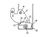
他方、図2に示すように、カマ2に関しスライダ6とは反対方向、すなわち下方には、前後方向に延在する制御レバー12が配設されている。
【0021】
この制御レバー12は、中央部を前記第一支軸4に平行な第二支軸13の回りを回動可能に支承されると共に、圧縮コイルばねとしての制御ばね14の弾力により、制御レバー12の前部をカマ2に近接する方向に、すなわち図2で時計方向に付勢している。
【0022】
一方、前記スライダ6の後端縁下端部は図2で向こう側に切り起こされてストッパー15が形成されている。
【0023】
他方、カマ2の鈎部5に連なる円弧部2aの終端には、突部としての第一係合部16が形成されている。
【0024】
また、制御レバー12の前端上部には凹部としての第二係合部17が、上記ストッパー15の移動軌跡と交差する後端の下部には係止段部18が夫々形成されている。
【0025】
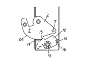
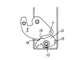
更にまた、制御レバー12の上端縁の前方には突部19が形成されており、カマ2の施錠方向の回動時、その鈎部5に連なる円弧部2a及び第一係合部16がこの突部19を押動して制御レバー12を前傾させるので、スライダのストッパー15が制御レバー12の後方を通過できる(図2乃至図5参照)。
【0026】
また、カマ2の第一係合部16から他端の係合ピン7にかけての外縁は少し凹んでおり、そのため、カマの第一係合部16が制御レバーの第二係合部17に落込んだとき(図6及び図7参照)、制御レバーの突部19がこの凹みに係合するので、制御レバー12は図で時計方向に回動し、制御レバー12の第二係合部17は第二支軸13よりかなり上方の位置を占めるに致る。
【0027】
なお、図2で符号21はこの引戸用施錠機構の安全装置の探り杆を示し、この安全装置は、引戸が完全に閉っていないときにはカマの鈎部5を振出せないようにしたものである。
【0028】
すなわち、この探り杆21は、探り杆ばね22の弾力により前方に付勢されているが、図2に示す解錠状態では、探り杆21の後端部に突設された係合突起23がスライダ6に形成された係合段部24と係合し、図示の錠箱内に引っ込んだ位置をとる。
【0029】
引戸を施錠するためスライダ6を下降させると、上記係合突起23と係合段部24との係合が外れ、以降、探り杆ばね22の弾力により探り杆21は前方に移動すると共に、係合突起23はスライダ6に形成された傾斜端縁25に沿って相対的に上昇しようとする。
【0030】
引戸が閉っているときには、移動する探り杆21の先端が召し合わせとなる他方の框に当接し、それ以上前方に移動しないので、その時点で探り杆21とスライダ6との連係が断たれ、スライダ6は自由に下降してカマ2が振出される。
【0031】
一方、引戸が完全に閉っていないときには、探り杆21は自由に前進し、その係合突起23が傾斜端縁25の上端に形成されたストッパー段部26と係合するので、スライダ6は探り杆21に係止されてそれ以上下降することができず、したがってカマ2を振出すことができない。
【0032】
この安全装置は、引戸が閉っていないときカマ2を振出すとカマが相手方の引戸と衝突するのでそれを防止するために設けられており、その構造は周知であるから更に詳細な説明は省略する。
【0033】
この発明の一実施例による引戸用施錠機構は上記のように構成されているので、引戸を完全に閉めた状態で室内側の摘みを下ろし、図2に示す解錠位置からスライダ6を下降させると、スライダの案内長孔8の開口端縁がカマ2の係合ピン7を駆動し、カマ2は時計方向に回動して鈎部5をフロント板3から振出し始める。
【0034】
解錠時には鈎部5の外端縁に弾圧されていた制御レバー12は、やがてカマの円弧部2aにより更に前傾させられ、この前傾姿勢は図3に及び図4に示す状態、すなわち、スライダ6のストッパー15が制御レバー12の後方を摺り抜けて通過するまで保持される。
【0035】
ストッパー15が制御レバー12の後方を通過すると、図5に示すように、カマの第一係合部16が制御レバー12の突部19との摺接点を前方に移動させつつ前進する。
【0036】
第一係合部16と制御レバー12の突部19との係合が外れると、図6に示すように、制御レバー12はカマ2からは自由になるが、後端の係止段部18がスライダのストッパー15に係止されるので図6の角度位置をとる。
【0037】
更にカマ2が時計方向に回動し、ストッパー15が下降すると、図7に示すように、制御レバーの突部19がカマ2の凹みに入り込み、制御レバー12はほぼ水平な角度位置をとり、このときにはその第二係合部17が第一支軸4と第二支軸13との間にあることは前記したとおりである。
【0038】
図7に示す施錠状態では、カマ2の第一係合部16が制御レバーの第2係合部に前方から係合可能に臨んでおり、この状態で何等かの手段により鈎部5を錠箱内に引っ込めようとすると、第一係合部16と第二係合部17との係合により制御レバー12が時計方向に駆動されるが、係止段部18がストッパー15に衝止されるので、カマ2を動かすことはできない。
【0039】
一方、この施錠機構を解錠するには前記したようにスライダ6を上昇させるのだが、このときにはスライダと一体のストッパー15が係止段部18を下方から撥ね上げるようにして制御レバー12を反時計方向に駆動するので(図5乃至図7参照)、このとき制御レバーの第二係合部17が下降してカマ2の第一係合部を自由にし、解錠が可能になる。
【0040】
なお、図示の実施例ではカマ側の第一係合部16を突部とし、制御レバー側の第二係合部17を凹部としたが、これは逆に第一係合部16を凹部とし、第二係合部17を突部としてもよいことは勿論である。
【0041】
【発明の効果】
以上の説明から明らかなように、この発明は、施錠時錠箱のフロント板から振出される鈎部を有するカマと、上下方向に移動可能に案内され、カマを出し入れするスライダを有する引戸用施錠機構において、カマに関しスライダとは反対側に、フロント板に垂直な前後方向に延在し、中央部を第二支軸により揺動可能に支承された制御レバーを設け、施錠時カマによって制御レバーを前傾させ、スライダの先端後方に設けられたストッパーを制御レバーの後端をかすめるように通過させてその係止段部に下方から係合可能に臨ませると共に、カマに形成された第一係合部を第二支軸より上方に位置する制御レバーの第二係合部に前方から係合可能に臨ませたので、鈎部を錠箱内に押込もうとする力は制御レバーを介してストッパーに衝止され、したがってカマを錠箱内に押し戻すことはできず、引戸の施錠機構の安全性を向上させることができる、という所期の効果を奏する。
【図面の簡単な説明】
【図1】この発明の一実施例による引戸用施錠機構を内蔵した錠箱の平面図。
【図2】疎の一部断面側面図。
【図3】スライダの施錠方向の移動行程の終端付近の状態を示す線図で、図面を明瞭にするためスライダ本体等の図示を省略して示す。
【図4】スライダの施錠方向の移動行程の終端付近においてストッパーが制御レバーの後方を通過する状態を示す線図で、図面を明瞭にするためスライダ本体等の図示を省略して示す。
【図5】図4と同様の線図で、図4に示す状態よりも更にスライダが下降した状態を示す。
【図6】図5と同様の線図で、カマと制御レバーとの係合が解かれているが、後者の係止段部がストッパーに乗り上がっている状態を示す。
【図7】図6と同様の線図で、施錠状態を示す。
【符号の説明】
1 錠箱
2 カマ
3 フロント板
4 第一支軸
5 鈎部
6 スライダ
7 係合ピン
8 案内長孔
12 制御レバー
13 第二支軸
14 制御ばね
15 ストッパー
16 第一係合部
17 第二係合部
18 係止段部
19 突部[0001]
BACKGROUND OF THE INVENTION
The present invention relates to a sliding door locking mechanism, and more particularly, to a novel sliding door locking mechanism capable of preventing a hook from being pushed back into a lock box.
[0002]
[Prior art]
The sliding door locking mechanism is usually configured to swing out a bowl-shaped member called a hook from the front plate of a lock box attached to one sliding door and hook it on the strike plate of the other sliding door.
[0003]
In the sliding door locking mechanism having a simple structure, the hook is moved in and out of the front plate of the lock box by a slider that moves up and down in conjunction with a knob operated from the indoor side.
[0004]
[Problems to be solved by the invention]
However, since the mechanism is generally reversible, for example, even if the knob of the sliding door locking mechanism is driven in the locking direction to swing the hook from the front plate and hook the hook on the strike plate of the other party's sliding door, Conversely, if the hook is turned back into the lock box by means, the slider returns to the unlocking direction in conjunction with the movement of the hook, resulting in unlocking, which may not be useful as a lock.
[0005]
An object of the present invention is to provide a sliding door locking mechanism that cannot return the hook once swung out into the lock box from the outside, and to improve the safety of the sliding door locking mechanism.
[0006]
[Means for Solving the Problems]
In order to achieve the above object, the present invention is provided in a lock box mounted on a sliding door. The center portion is supported so as to be rotatable around a horizontal first support shaft in the vicinity of the front plate. A hook that swings out of the plate and has a hook portion that engages with the strike plate of the other sliding door, and a slider that is guided to move up and down in a positional relationship that partially overlaps with the hook. The engaging pin projecting on either one of the other end and the slider and the guide slot opening on the other are engaged, and the hook is moved in and out of the front plate by moving the slider in the vertical direction. The control lever that extends in the front-rear direction perpendicular to the front plate is disposed on the opposite side of the slider from the slider, and the central portion of the control lever extends around the second support shaft parallel to the first support shaft. While being pivotably supported, The front part of the control lever that is closer to the front plate is biased in the direction closer to the hook, while a stopper is formed behind the part closest to the control lever of the slider, and a first engagement part is formed on the outer edge of the hook. On the other hand, a second engaging part is formed at the part facing the front end of the control lever, and a locking step part is formed at a part intersecting the movement locus of the stopper at the rear end. The shape of the outer edge of the control lever is set so that it pushes the front end of the control lever against the urging force in the direction away from the hook, so that the stopper can pass behind the control lever tilted forward, and locking The first engaging portion is made to be able to engage from the front to the second engaging portion between the first supporting shaft and the second supporting shaft in the vertical direction, and the slider stopper is set to the locking step of the control lever. part so as to engage in, other than Te, lock box and sickle The other to a force pushing on, characterized in that so as to衝止the stopper through the engagement and control levers of the first and second engagement portions.
[0007]
【Example】
An embodiment of the present invention will be described below with reference to the drawings.
[0008]
In this
[0009]
At one end (the lower end in FIG. 2) of the
[0010]
By the way, the
[0011]
A
[0012]
An
[0013]
The
[0014]
On the other hand, an
[0015]
The
[0016]
An
[0017]
Therefore, when the
[0018]
However, after that, the
[0019]
Therefore, when the knob is pushed down, or when the knob is pushed up, there is resistance to the knob in the first stroke, and in the latter stroke, the knob is lightened and a kind of click feeling is generated. However, this open leg spring is not an essential component of the present invention.
[0020]
On the other hand, as shown in FIG. 2, a
[0021]
The
[0022]
On the other hand, the lower end portion of the rear edge of the
[0023]
On the other hand, a
[0024]
Further, a second engaging
[0025]
Furthermore, a
[0026]
Further, the outer edge from the first engaging
[0027]
In FIG. 2,
[0028]
That is, the
[0029]
When the
[0030]
When the sliding door is closed, the tip of the moving
[0031]
On the other hand, when the sliding door is not completely closed, the
[0032]
This safety device is provided to prevent the hook from colliding with the other party's sliding door when the sliding
[0033]
Since the sliding door locking mechanism according to one embodiment of the present invention is configured as described above, the knob on the indoor side is lowered with the sliding door fully closed, and the
[0034]
At the time of unlocking, the
[0035]
When the
[0036]
When the engagement between the
[0037]
Further, when the
[0038]
In the locked state shown in FIG. 7, the first engaging
[0039]
On the other hand, in order to unlock this locking mechanism, the
[0040]
In the illustrated embodiment, the
[0041]
【The invention's effect】
As is apparent from the above description, the present invention provides a sliding door lock having a hook having a hook portion that is swung out from the front plate of the lock box at the time of locking, and a slider that is guided so as to be movable in the vertical direction. In the mechanism, a control lever that extends in the front-rear direction perpendicular to the front plate on the opposite side of the slider with respect to the hook is provided, and the central portion is supported so as to be swingable by the second support shaft. Is tilted forward, and a stopper provided at the rear of the front end of the slider is passed so that the rear end of the control lever is squeezed so that the engaging step can be engaged from below, and the first formed on the hook Since the engaging portion is made to be able to engage with the second engaging portion of the control lever located above the second support shaft from the front, the force to push the collar portion into the lock box is passed through the control lever. Is stopped by the stopper Therefore it is impossible to push the hook in the lock box, it is possible to improve the safety of the locking mechanism of the sliding door, it exhibits the desired effect.
[Brief description of the drawings]
1 is a plan view of a lock box incorporating a sliding door locking mechanism according to an embodiment of the present invention;
FIG. 2 is a sparse partial cross-sectional side view.
FIG. 3 is a diagram showing a state in the vicinity of the end of a moving stroke in the locking direction of the slider, in which the slider body and the like are not shown for the sake of clarity.
FIG. 4 is a diagram showing a state in which the stopper passes behind the control lever in the vicinity of the end of the moving stroke in the locking direction of the slider, and the slider body and the like are not shown for the sake of clarity.
5 is a diagram similar to FIG. 4, showing a state where the slider is further lowered than the state shown in FIG.
FIG. 6 is a diagram similar to FIG. 5 and shows a state in which the engagement between the hook and the control lever is disengaged, but the latter locking stepped portion rides on the stopper.
FIG. 7 is a diagram similar to FIG. 6 and shows a locked state.
[Explanation of symbols]
DESCRIPTION OF
Claims (1)
Priority Applications (1)
| Application Number | Priority Date | Filing Date | Title |
|---|---|---|---|
| JP12721499A JP4222684B2 (en) | 1999-05-07 | 1999-05-07 | Locking mechanism for sliding doors |
Applications Claiming Priority (1)
| Application Number | Priority Date | Filing Date | Title |
|---|---|---|---|
| JP12721499A JP4222684B2 (en) | 1999-05-07 | 1999-05-07 | Locking mechanism for sliding doors |
Publications (2)
| Publication Number | Publication Date |
|---|---|
| JP2000320214A JP2000320214A (en) | 2000-11-21 |
| JP4222684B2 true JP4222684B2 (en) | 2009-02-12 |
Family
ID=14954561
Family Applications (1)
| Application Number | Title | Priority Date | Filing Date |
|---|---|---|---|
| JP12721499A Expired - Fee Related JP4222684B2 (en) | 1999-05-07 | 1999-05-07 | Locking mechanism for sliding doors |
Country Status (1)
| Country | Link |
|---|---|
| JP (1) | JP4222684B2 (en) |
Cited By (1)
| Publication number | Priority date | Publication date | Assignee | Title |
|---|---|---|---|---|
| CN108779654A (en) * | 2016-03-14 | 2018-11-09 | 马科技术有限责任公司 | Assembling assembly for being safely locked in window, door etc. on lockplate |
Families Citing this family (7)
| Publication number | Priority date | Publication date | Assignee | Title |
|---|---|---|---|---|
| JP4948137B2 (en) * | 2006-11-29 | 2012-06-06 | 美和ロック株式会社 | Joinery lock |
| JP4975516B2 (en) * | 2007-05-09 | 2012-07-11 | 三協立山アルミ株式会社 | Sliding door security lock |
| KR200453457Y1 (en) | 2009-04-08 | 2011-05-09 | 주식회사 쓰리지테크놀러지 | Window automatic lock |
| JP5457328B2 (en) * | 2010-11-11 | 2014-04-02 | Ykk Ap株式会社 | Locking and unlocking device and joinery |
| CN109025510B (en) * | 2018-07-17 | 2023-06-27 | 陈秀琴 | Magnetic lock body |
| CN111260845B (en) * | 2020-01-15 | 2022-05-31 | 深圳市萝趣物联网科技有限公司 | Automatic vending machine |
| CN113863419B (en) * | 2021-11-09 | 2024-09-17 | 成都开源智创工程机械设备有限公司 | Lift release device |
-
1999
- 1999-05-07 JP JP12721499A patent/JP4222684B2/en not_active Expired - Fee Related
Cited By (1)
| Publication number | Priority date | Publication date | Assignee | Title |
|---|---|---|---|---|
| CN108779654A (en) * | 2016-03-14 | 2018-11-09 | 马科技术有限责任公司 | Assembling assembly for being safely locked in window, door etc. on lockplate |
Also Published As
| Publication number | Publication date |
|---|---|
| JP2000320214A (en) | 2000-11-21 |
Similar Documents
| Publication | Publication Date | Title |
|---|---|---|
| JP4222684B2 (en) | Locking mechanism for sliding doors | |
| WO2007055200A1 (en) | Latch device of door | |
| JP2003070968A (en) | Game machine locking device | |
| JP3569960B2 (en) | Vending machine door lock device | |
| JP3914139B2 (en) | Door latch device | |
| JP4707551B2 (en) | Game machine locking device | |
| CN117922394A (en) | Anti-misuse safety seat support | |
| JP4117808B2 (en) | Ball winning device for pachinko machines | |
| JP4354603B2 (en) | Door lock device | |
| JPH0645979B2 (en) | Electric lock | |
| JP3146820B2 (en) | Vending machine door lock mechanism | |
| JPH094303A (en) | Sickle-like bolt lock of temporary lock type | |
| JPH04221182A (en) | Mortise lock device | |
| JP3636115B2 (en) | Door lock unit | |
| JP3964006B2 (en) | Sliding door lock device | |
| JP4295547B2 (en) | Locking mechanism | |
| JP2019157529A (en) | Hook lock | |
| JP4011416B2 (en) | Door to door | |
| JP2877394B2 (en) | Tablets | |
| JP4351318B2 (en) | Door lock device | |
| JP3753870B2 (en) | Release mechanism of opening / closing body locking device for automobile | |
| JPH0743405Y2 (en) | Heart lock | |
| JP4181714B2 (en) | Window guard arm device | |
| JP3767929B2 (en) | Lock mechanism and ball game machine for a ball game machine | |
| JPS5933931Y2 (en) | High frequency heating device |
Legal Events
| Date | Code | Title | Description |
|---|---|---|---|
| A621 | Written request for application examination |
Free format text: JAPANESE INTERMEDIATE CODE: A621 Effective date: 20050928 |
|
| A977 | Report on retrieval |
Free format text: JAPANESE INTERMEDIATE CODE: A971007 Effective date: 20080619 |
|
| A131 | Notification of reasons for refusal |
Free format text: JAPANESE INTERMEDIATE CODE: A131 Effective date: 20080623 |
|
| A521 | Written amendment |
Free format text: JAPANESE INTERMEDIATE CODE: A523 Effective date: 20080822 |
|
| TRDD | Decision of grant or rejection written | ||
| A01 | Written decision to grant a patent or to grant a registration (utility model) |
Free format text: JAPANESE INTERMEDIATE CODE: A01 Effective date: 20080912 |
|
| A01 | Written decision to grant a patent or to grant a registration (utility model) |
Free format text: JAPANESE INTERMEDIATE CODE: A01 |
|
| R155 | Notification before disposition of declining of application |
Free format text: JAPANESE INTERMEDIATE CODE: R155 |
|
| A61 | First payment of annual fees (during grant procedure) |
Free format text: JAPANESE INTERMEDIATE CODE: A61 Effective date: 20081118 |
|
| R150 | Certificate of patent or registration of utility model |
Free format text: JAPANESE INTERMEDIATE CODE: R150 |
|
| FPAY | Renewal fee payment (event date is renewal date of database) |
Free format text: PAYMENT UNTIL: 20111128 Year of fee payment: 3 |
|
| FPAY | Renewal fee payment (event date is renewal date of database) |
Free format text: PAYMENT UNTIL: 20121128 Year of fee payment: 4 |
|
| LAPS | Cancellation because of no payment of annual fees |