JP4222672B2 - Transportation equipment using mobile objects - Google Patents
Transportation equipment using mobile objects Download PDFInfo
- Publication number
- JP4222672B2 JP4222672B2 JP05485199A JP5485199A JP4222672B2 JP 4222672 B2 JP4222672 B2 JP 4222672B2 JP 05485199 A JP05485199 A JP 05485199A JP 5485199 A JP5485199 A JP 5485199A JP 4222672 B2 JP4222672 B2 JP 4222672B2
- Authority
- JP
- Japan
- Prior art keywords
- moving
- moving body
- platform
- path
- platforms
- Prior art date
- Legal status (The legal status is an assumption and is not a legal conclusion. Google has not performed a legal analysis and makes no representation as to the accuracy of the status listed.)
- Expired - Fee Related
Links
Images


Landscapes
- Intermediate Stations On Conveyors (AREA)
Description
【0001】
【発明の属する技術分野】
本発明は、たとえば床側を走行自在な非駆動式の移動体を一定の循環経路上で移動させて、この移動体により支持している被搬送物を搬送するのに利用される移動体使用の搬送設備に関するものである。
【0002】
【従来の技術】
従来、非駆動式の移動体を一定経路上で移動させるものとして、たとえば特開平2−209309号公報に見られる構成が提供されている。
この従来構成は、可動体が走行自在な一定経路の上手に可動体搬送装置が設けられるとともに、下手にブレーキ装置が設けられている。そして可動体搬送装置は、可動体の側面に当接自在な左右一対の送りローラと、これら送りローラに連動する回転駆動装置とから構成されている。またブレーキ装置は、可動体の側面に当接自在な左右一対のブレーキローラと、これらブレーキローラに逆送り回転力を付与するトルクモータとから構成されている。
【0003】
このような従来の構成によると、可動体の両側面に当接している両送りローラを回転駆動装置により強制回転させることで、可動体に大きな推進力を与えることになり、以て可動体を一定経路上で移動し得る。その際に可動体は、先行し停止している可動体群を後押しして移動させることになる。
一定経路の下手においては、逆送り回転されているブレーキローラが可動体の両側面に当接していることから、この可動体に逆搬送方向の推進力が作用し、ここで送り回転力が逆送り回転力よりも大であることから、その差に相応してブレーキローラが送り回転側に回転される。これにより下手の可動体は、ブレーキ作用を受けた状態で移動されることになり、したがって可動体群は前後端間に隙間を生じめることなく密な後押し状態で移動される。
【0004】
【発明が解決しようとする課題】
上記した従来の構成によると、可動体により搬送される被搬送物に対して作業者による各種作業を遂行する際に、作業者は移動状態の被搬送物に対して床側から行わなければならず、各種作業は容易に行えない。これに対しては、被搬送物に対して可動体の本体形状を大きくし、この本体上に作業者が乗り込んで、被搬送物に対して各種作業を遂行することが考えられる。しかし、この場合には可動体の全長が長くなり、短い被搬送物を搬送しながらの各種作業経路部などにおいては、所望台数を移動させるときに経路長さが長くなり、設備全体の設置スペースが広くなるなど、問題点が生じることになる。
【0005】
本発明の目的とするところは、移動体群を、前後端間に隙間を生じめることなく密な後押し状態で移動し得る形式でありながら、移動体は、いずれも作業者が乗り込み得る長い被搬送物用の長尺形態と短い被搬送物用の短尺形態とに切り換え得る移動体使用の搬送設備を提供する点にある。
【0006】
【課題を解決するための手段】
前述した目的を達成するために、本発明のうちで請求項1記載の移動体使用の搬送設備は、上位の後押し経路部と、下位の復帰経路部と、これら経路部の始終端を結ぶ昇降経路部とにより移動体群の循環経路が形成され、前記後押し経路部と復帰経路部に移動体を支持案内するレールが設けられるとともに、両昇降経路部には移動体の移載手段が設けられ、前記移動体は、上部側に被搬送物の支持装置が設けられるとともに、その前後端の少なくとも一方にはプラットフォームが上下揺動自在に設けられ、このプラットフォームは、移動体の前後端間に隙間を生じめることなく後押し状態で移動する状態とし、かつ移動体を長尺形態と短尺形態とに切り換え自在とすべく、水平状へ上動して固定することによりその遊端が隣接した移動体側に当接自在に構成され、かつ縦向き状への下動により、前後の移動体がプラットフォームのスペース相当分を詰めて当接自在に構成され、前記後押し経路部には、その上手側に、移動体に移動力を付与する送り装置が設けられるとともに、下手側に、移動体に制動力を付与する制動装置が設けられていることを特徴としたものである。
【0007】
したがって請求項1の発明によると、移動体は、後押し経路部、昇降経路部、復帰経路部、昇降経路部と、循環経路で移動させ得る。そして後押し経路部では、その上手側において送り装置により移動体に移動力を付与するとともに、下手側において制動装置により移動体に制動力を付与することで、移動体群を、前後端間に隙間を生じめることなく密な後押し状態で移動し得る。
【0008】
その際に、プラットフォームを水平状に上動させることにより、移動体群を、作業者が乗り込み得る長い被搬送物用の長尺形態として、前後端間に隙間を生じめることなく密な後押し状態で移動し得る。また、プラットフォームを縦向き状に下動させ、前後の移動体を、プラットフォームのスペース相当分を詰めて当接させることにより、移動体群を、作業者が乗り込み得る短い被搬送物用の短尺形態として、前後端間に隙間を生じめることなく密な後押し状態で移動し得る。
【0009】
また本発明の請求項2記載の移動体使用の搬送設備は、上記した請求項1記載の構成において、移動体の前後両端にそれぞれプラットフォームが上下揺動自在に設けられ、これらプラットフォームは各別に水平状へ上動して固定自在であることを特徴としたものである。
したがって請求項2の発明によると、移動体は、両プラットフォームを水平状に上動させた長尺形態と、一方のプラットフォームを水平状に上動させかつ他方のプラットフォームを縦向き状に下動させた中間尺形態と、両プラットフォームを縦向き状に下動させた短尺形態とに切り換え得る。
【0010】
そして本発明の請求項3記載の移動体使用の搬送設備は、上記した請求項1または2記載の構成において、移動体とプラットフォームとの側面に亘って受動面が形成され、送り装置と制動装置には、前記受動面に当接自在なローラが設けられていることを特徴としたものである。
したがって請求項3の発明によると、送り装置のローラを移動体やプラットフォームの受動面に当接させることで、移動体に移動力を付与し得、そして制動装置のローラを移動体やプラットフォームの受動面に当接させることで、移動体に制動力を付与し得る。
【0011】
【発明の実施の形態】
以下に、本発明の実施の形態を、図に基づいて説明する。
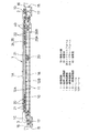
図1、図2において、多数の移動体20が移動自在な循環経路1は、上位の後押し経路部1Aと、下位の復帰経路部1Bと、これら経路部1A,1Bの始終端を結ぶ昇降経路部1C,1Dなどにより構成されている。そして後押し経路部1Aの始端側には、移動体20側に被搬送物の積み込みを行う積み込み部2が形成され、また後押し経路部1Aの終端側には、移動体20から被搬送物を卸す卸し部3が形成されている。
【0012】
前記後押し経路部1Aには、その上手側に、移動体20に移動力を付与する送り装置4が設けられるとともに、下手側に、前記移動体20に制動力を付与する制動装置5が設けられ、また復帰経路部1Bも同様に、その上手側に高速送り装置6が、下手側に制動装置7が設けられている。
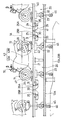
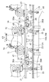
図1〜図5において、後押し経路部1Aと復帰経路部1Bには、移動体20を支持案内する左右一対のレール12A,12Bが床10側からの機枠11に配設されている。また両昇降経路部1C,1Dには移動体20の移載手段15が設けられ、これら移載手段15は、昇降台16と、この昇降台16に連動される昇降駆動装置17と、前記昇降台16上に配設され前記レール12A,12Bに対して接続可能な昇降レール18などにより構成されている。
【0013】
前記移動体20は台車形式であって、その本体21は前後方向で長い矩形板状(方形板状)に形成され、そして本体21の前後部分に設けられた左右一対の車輪22を介して前記レール12A,12Bに支持案内されるとともに、左右における一方側の車輪22の近くに設けられた被案内装置(ガイドローラなど)23を介して前記レール12A,12Bに案内されている。そして前記本体21の前面と後面とは、前後の移動体20を接近させたときに互いに当接自在な当接部24,25に形成されている。
【0014】
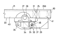
図1〜図8において、前記本体21の前後両端(前後端の少なくとも一方)には、それぞれ左右方向に長い長尺板状のプラットフォーム26A,26Bが各別に上下揺動自在に設けられる。すなわち、本体21の前後両端で下部側には、軸受27を介して左右方向軸28が回転自在に設けられ、この左右方向軸28に基端が固定された左右一対の腕体29の遊端間にプラットフォーム26A,26Bが連結されている。
【0015】
これによりプラットフォーム26A,26Bは、左右方向軸28の軸心を揺動軸心28aとして各別に上下揺動自在に構成される。そしてプラットフォーム26A,26Bの水平状姿勢における外面と内面との遊端は当接部30,31に形成されている。その際にプラットフォーム26A,26Bは、水平状への揺動により、その内面の当接部31が本体21の当接部24,25に当接自在に構成されるとともに、隣接した移動体20間においては、その外面の当接部30どうしが互いに当接自在に構成されている。
【0016】
また、両プラットフォーム26A,26Bが縦向き状へ揺動されたとき、前後の移動体20の本体21、すなわち、先行本体21の後面の当接部25に対して後続本体21の前面の当接部24が、これらプラットフォーム26A,26Bのスペース相当分を詰めて当接自在に構成されている。さらにプラットフォーム26A,26Bのうち、いずれか一方のみが縦向き状へ揺動されたとき、水平状のプラットフォーム26A,26Bの外面の当接部30が、縦向き状のプラットフォーム26A,26Bのスペース相当分を詰めて、前後の当接部24,25に当接自在に構成されている。
【0017】
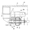
前記プラットフォーム26A,26Bは、水平状へ上動(揺動)したときに各別に固定自在に構成され、そのための固定手段33が移動体20の幅方向(左右方向)の両側に設けられている。
この固定手段33は、移動体20の本体21側から連設された板状の被係止部材34と、プラットフォーム26A,26Bの揺動軸心28aを中心とした円弧上の二箇所に位置されるように被係止部材34に設けられた被係止孔(被係止部の一例)35,36と、前記プラットフォーム26A,26Bの下面側に設けられた左右方向のガイド筒体37と、このガイド筒体37に支持案内されて前記揺動軸心28aに沿って摺動自在に設けられた係止ピン(係止体の一例)38などにより構成されている。ここで係止ピン38は、両被係止孔35,36に対して係脱自在であり、そしてガイド筒体37の部分に配設された圧縮ばね39によって係合方向に付勢されている。
【0018】
前記本体21の左右の両側面とプラットフォーム26A,26Bの左右の両側面とは、それぞれ受動面40,41に形成されている。
前記移動体20の上部側、すなわち、前記本体21の上部には被搬送物の支持装置43が設けられる。ここで被搬送物は二輪車70であり、その前輪71や後輪72を介して支持装置43に支持され、そのために支持装置43は、前輪支持部43Aと後輪支持部43Bとからなる。
【0019】
これら支持部43A,43Bは、本体21に上下方向に設けられた筒状のガイド体44と、このガイド体44に案内されて昇降自在なロッド体45と、このロッド体45の下端に設けられたカムローラ46と、前記ロッド体45の上端に設けられた車輪受け体47などにより、その支持位置を上下方向で変位自在として構成されている。なお後輪支持部43Bにおける車輪受け体47には、後輪72を幅方向で規制する規制手段48が設けられている。
【0020】
前記後押し経路部1Aには、前輪支持部43Aと後輪支持部43Bとを上下方向で各別に変位させるための一対のカムレール13A,13Bが配設されている。これらカムレール13A,13Bは前記機枠11側に敷設され、前記ロッド体45の下端に設けられたカムローラ46を、下方から支持案内するように構成されている。その際にカムレール13A,13Bは左右方向において位置をずらして配設され、そして前輪支持部43Aと後輪支持部43Bとのカムローラ46も位置をずらすことで、前輪支持部43Aと後輪支持部43Bとが各別に上下方向で変位されることになる。
【0021】
前記後押し経路部1Aにおいて、制動装置5と移載手段15との間には送り込み装置50が配設され、また復帰経路部1Bにおいて、移載手段15と送り装置6との間には引き出し装置51が配設されている。そして復帰経路部1Bの中間部分には減速装置52と加速装置53とが配設され、さらに復帰経路部1Bにおいて、制動装置7と移載手段15との間には、所定間隔置きの四箇所(複数箇所)に順送り装置54,55,56,57が配設されている。なお、移載手段15における昇降台16には送り出し装置58が配設されている。
【0022】
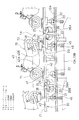
前記移動体20に移動力を付与する前記送り装置4,6は、たとえば図4、図5に示すように左右に振分けて配設されており、それぞれ前記機枠11側に設けられた支持部材60と、この支持部材60側に縦軸61を介して揺動自在に設けられた腕体62と、この腕体62の遊端に設けられた駆動装置63と、この駆動装置63からの駆動軸64に設けられたローラ(駆動輪体)65などにより構成されている。そして揺動装置(図示せず。)により腕体62を揺動させて、駆動装置63によって強制駆動されているローラ65を前記受動面40,41に当接させることで、前記移動体20に移動力を付与するように構成されている。
【0023】
前記移動体20に制動力を付与する前記制動装置5,7は、前記送り装置4,6と同様な構成であって、そのローラ(制動輪体)65を前記受動面44,45に当接させることで、前記移動体20に制動力を付与するように構成されている。ここで制動装置5,7は、前記送り装置4,6と同一方向の回転力を、送り装置4,6の回転速度に対して低速でかけることによって制動力を付与するように構成されているが、この制動装置5,7としては、逆方向の回転力が付与される構成であってもよい。
【0024】
そして復帰経路部1Bの高速送り装置6は、そのローラ65を高速回転させることで移動体20に高速の移動力を付与し得、以て送り装置6と制動装置7の間においては一台の移動体20を惰性を含めて高速で復帰移動させるように構成されている。なお復帰経路部1Bの中間部分に、前記送り装置4,6や制動装置5,7と同様の前記減速装置52と加速装置53とが配設されていることにより、一台の移動体20の高速での復帰移動をより確実化させているが、復帰経路部1Bの距離が短い場合には、これら減速装置52や加速装置53は省略し得る。
【0025】
前記送り込み装置50や引き出し装置51や各順送り装置54,55,56,57や送り出し装置58は、その左右の一方が前記送り装置4,6と同様な構成であり、そして定置ローラ67に対してローラ65を接近離間揺動させるように構成されている。前記順送り装置54〜57の部分の側方には移動体20のストレージ部59が形成され、このストレージ部59と復帰経路部1Bとの間で移動体20を移し替え自在に構成されている。
【0026】
以下に、上記した実施の形態における作用を説明する。
まず、全体の流れを説明するが、このとき全ての移動体20は、プラットフォーム26A,26Bが縦向き状に下動されているものとする。すなわちプラットフォーム26A,26Bは、図3〜図6に示されるように、その腕体29を介して揺動軸心28aの周りに下動され、そして被係止孔36に係止ピン38を係合させるとともに、その係合姿勢を圧縮ばね39の付勢力で維持することによって、下動姿勢が固定手段33により固定されている。
【0027】
図1、図2に示すように、移載手段15により昇降経路部1Dで上昇される空の移動体20は、その上昇限により、後押し経路部1Aの始端である積み込み部2に位置され、この積み込み部2において、適宜の手段によって支持装置43上に二輪車70が積み込まれる。そして移動体20は、昇降台17に設けられた送り出し装置58により、この昇降台17上から送り出される。すなわち移動体20は、送り出し装置58の送り出し力によって、その車輪22が昇降レール18からレール12Aに案内されることで、後押し経路部1Aの始端に設けられた送り装置4へと移動される。
【0028】
このとき送り装置4のローラ65は、送り出し装置58による送り出し時に図5の仮想線に示すように非作用位置にあり、そして送り出し後に、図5の実線や図4に示すように、作用位置へと揺動して受動面40に当接(圧接)される。これにより、両ローラ65によって本体21を挟持するのであるが、このときローラ65は駆動装置63によって回転駆動されている。したがって強制回転されているローラ65を受動面40に当接させることで、その送り回転力により移動体20に移動力を与えることになり、以て移動体20は送り装置4により、後押し経路部1A上において所望の速度で送り移動される。
【0029】
その際に図3に示すように、後押し経路部1A上に密な列車状で位置している移動体20群のうち、最後尾の移動体20における本体21の後端部の当接部25に、この送り込まれた移動体20における本体21の前端部の当接部24が当接され、以て送り装置4による送り込み力で、後押し経路部1Aに密な列車状で位置している移動体20群を後押し移動させることになる。このような移動の際に、各車輪22はレール12Aに支持案内され、そして被案内装置23がレール12Aに案内されることで、移動体20は、ガタ付くことなく、かつ横ずれなどが阻止された状態で移動される。
【0030】
このようにして、後押し経路部1A上で移動されている移動体20群のうち、後押し経路部1Aの終端近くに位置されている移動体20には、制動装置5によって制動力が付与されている。すなわち、送り装置4による移動体20の移動作業が停止しているとき、制動装置5におけるローラ65は、図5の仮想線に示すように非作用位置にある。そして、送り装置4の送り動に連動して、ローラ65は図5の実線に示すように、作用位置へと揺動して受動面41に当接(圧接)される。
【0031】
これにより、両ローラ65によって本体21を挟持するのであるが、このときローラ65は回転駆動されている。すなわち駆動装置63の駆動によりローラ65は低速で強制回転されている。したがって強制回転されているローラ65を受動面40に圧接させたとき、その制動回転力によって移動体20に移動方向の推進力を作用させるが、ここで送り回転力が制動回転力よりも大きいことから、その差に相応してローラ65の部分に滑りが発生され、そのときの負荷はトルクモータにより吸収される。
【0032】
これにより下手の制動装置5に対応した移動体20は、制動作用を受けた状態で移動されることになり、したがって送り装置4から制動装置5の間では、複数台の移動体20が、その前後端間に隙間を生じめることなく密な後押し状態で整列されることになる。なお、制動装置5のローラ65による制動作用、ならびに前述した送り装置4のローラ65による送り作用は、先行移動体20における本体21の受動面40から後続移動体20における本体21の受動面40へと、順次作用させることで行われる。
【0033】
このように、後押し経路部1Aにおいて移動体20が間欠移動されている間に、または停止されている間に、作業者によって、二輪車70に対して各種の作業を遂行し得る。その際に後押し経路部1Aにおいて移動体20群は、そのプラットフォーム26A,26Bが縦向き状へ揺動され、前後の移動体20の本体21間、すなわち、先行移動体20における本体21の後端部の当接部25に対して後続移動体20における本体21の前端部の当接部24が、両プラットフォーム26A,26Bのスペース相当分を詰めて当接されている。
【0034】
すなわち、後押し経路部1Aにおいて移動体20群は、作業者が乗り込み得る短い二輪車70用の短尺形態で、その前後端間に隙間を生じめることなく密な後押し状態で移動されることになり、以て後押し経路部1Aでは、移動体20の台数を増加させた効率のよい後押し移動を可能にし得る。
さらに、このように後押し経路部1Aにおいて移動体20群が移動されているとき、支持装置43における両支持部43A,43Bは、そのカムローラ46がそれぞれのカムレール13A,13Bに案内されることで各別に昇降動され、これにより各種の作業に応じて二輪車70を、昇降させたり前後で傾斜させたりし得る。
【0035】
前述したような後押しにより制動装置5の部分から出された移動体20は、後押し経路部1Aの終端部分において送り込み装置50による送り込み力を受け、昇降経路部1Cにおいて上昇されている移載手段15の昇降台16上に送り込まれて卸し部3に位置される。そして、この卸し部3において、適宜の手段によって支持装置43上から二輪車70が卸される。
【0036】
これにより空になった移動体20は、昇降台16とともに昇降経路部1Cで下降され、その下降限により、復帰経路部1Bの始端部分に位置される。そして移動体20は、昇降台16に設けられた送り出し装置58により、この昇降台16上から送り出される。すなわち移動体20は、送り出し装置58の送り出し力によって、その車輪22が昇降レール18からレール12Bに案内されることで、復帰経路部1Bの始端に設けられた引き出し装置51へと移動される。
【0037】
そして移動体20は、引き出し装置51により引き出されて高速送り装置6へと移動される。次いで移動体20は、高速送り装置6のローラ65を高速回転させることで高速の移動力が付与され、以て復帰経路部1B上を高速で復帰移動される。この復帰移動は惰性により行われ、その惰性の移動が次第に低速になったときに減速装置52に達し、ここで減速されたのち加速装置53により再び加速されて復帰経路部1B上を復帰移動されて制動装置7に達する。
【0038】
次いで制動装置7において制動されたのち、この制動装置7の部分から出てきた移動体20は、順送り装置54〜56により下手に順送りされ、下手端の順送り装置57による送り込み力を受け、昇降経路部1Dにおいて下降されている移載手段15の昇降台16上に送り込まれ、以て最初の状態に戻される。
次に両プラットフォーム26A,26Bを使用する状態を述べる。ここでプラットフォーム26A,26Bの切り換えは、たとえば、順送り装置54〜57の部分などで行われる。すなわち両プラットフォーム26A,26Bは、図7、図9に示されるように、その腕体29を介して揺動軸心28aの周りに上動され、そして被係止孔35に係止ピン38を係合させるとともに、その係合姿勢を圧縮ばね39の付勢力で維持することによって、上動姿勢が固定手段33により固定されている。
【0039】
これによりプラットフォーム26A,26Bは水平状姿勢となり、そして水平状への揺動により、その内面の当接部31が本体21の当接部24,25に当接されるとともに、隣接した移動体20間においては、その外面の当接部30どうしが互いに当接されることになる。
したがって後押し経路部1Aにおいて、後続移動体20の本体21に作用される送り装置4による送り込み力は、この本体21の前端の当接部24から、プラットフォーム26Aの内面側の当接部31へと伝達され、そしてプラットフォーム26Aの外面側の当接部30から、先行移動体20におけるプラットフォーム26Bの外面側の当接部30、プラットフォーム26Bの内面側の当接部31から本体21の後端の当接部25へと順次伝達され、以て移動体20群を後押し移動させる。その際に送り装置4による送り込み力は、プラットフォーム26Aの受動面41、本体21の受動面40、プラットフォーム26Bの受動面41へと、順次作用させることで行われる。
【0040】
これにより、後押し経路部1Aにおいて移動体20は、水平状のプラットフォーム26A,26Bにより、作業者が乗り込み得る長い二輪車70用の長尺形態とされることで、作業者は、任意なときに任意な時間、プラットフォーム26A,26B上に乗り込んで、各種の作業を容易に遂行し得る。なお、移動体20が長尺形態であることから、後押し経路部1Aでの後押し移動台数、すなわち循環経路1での循環台数は少なくなるが、その余剰台数はストレージ部59に取り出されてストレージされる。またストレージ部59の移動体20は、必要に応じて循環経路1に投入される。
【0041】
次に、前部のプラットフォーム26A(または後部のプラットフォーム26B)のみを使用する状態を述べる。すなわち図10に示すように、プラットフォーム26Aは、その腕体29を介して揺動軸心28aの周りに上動され、そして上動姿勢が固定手段33により固定されている。またプラットフォーム26Bは、その腕体29を介して揺動軸心28aの周りに下動され、そして下動姿勢が固定手段33により固定されている。
【0042】
したがって後押し経路部1Aにおいて、後続移動体20の本体21に作用される送り装置4による送り込み力は、この本体21の前端の当接部24から、プラットフォーム26Aの内面側の当接部31へと伝達され、そしてプラットフォーム26Aの外面側の当接部30から、先行移動体20における本体21の後端の当接部25へと順次伝達され、以て移動体20群を後押し移動させる。その際に送り装置4による送り込み力は、プラットフォーム26Aの受動面41、本体21の受動面40へと、順次作用させることで行われる。
【0043】
これにより、後押し経路部1Aにおいて移動体20群は、縦向きのプラットフォーム26Bのスペース相当分を詰めるとともに、水平状のプラットフォーム26Aにより、作業者が乗り込み得る中間の二輪車70用の中間尺形態とされて、後押し移動される。なお、移動体20の循環経路1での循環台数は、ストレージ部59を利用しての取り出しや投入により調整される。
【0044】
上記した実施の形態では、支持装置43として、上下で変位する昇降形式が示されているが、支持装置43としては、本体21に固定された形式などであってもよい。また被搬送物としては、二輪車120のほかに種々なものを取り扱えるのであり、支持装置43はそれに応じた形状となる。
上記した実施の形態では、送り装置4や制動装置5として摩擦ローラ形式が採用されているが、これは受動部をラックで形成し、送り装置4や制動装置5としてピニオンを用いたラック・ピニオン形式などであってもよい。
【0045】
上記した実施の形態では、本体21の前後両端それぞれにプラットフォーム26A,26Bが上下揺動自在に設けられているが、これは本体21の前端にのみプラットフォーム26Aが上下揺動自在に設けられた形式や、本体21の後端にのみプラットフォーム26Bが上下揺動自在に設けられた形式であってもよい。上記した実施の形態では、送り装置4,6として左右に駆動式のローラ65を採用し、制動装置5,7として左右に駆動式のローラ65を採用しているが、これは、一方のローラ65のみを強制駆動形式とし、他方を定置の遊転形式とした構成でもよい。
【0046】
上記した実施の形態では、被係止部として被係止孔35,36が、係止体として係止ピン38が示されているが、これは被係止部が凹部であり、この凹部に係止ピンの先端を係止させる形式など、種々な組み合せを採用し得る。
上記した実施の形態では、ピット部内の床10からの機枠11にレール12A,12Bなどを配設しており、これによると、移動体20を含めた全体の高さを低く形成できるが、これはピットを形成することなくレールなどを配設した構成であってもよい。
【0047】
【発明の効果】
上記した本発明の請求項1によると、移動体は、後押し経路部、昇降経路部、復帰経路部、昇降経路部と、循環経路で移動でき、そして後押し経路部では、その上手側において送り装置により移動体に移動力を付与するとともに、下手側において制動装置により移動体に制動力を付与することで、移動体群を、前後端間に隙間を生じめることなく密な後押し状態で移動できる。
【0048】
その際に、プラットフォームを水平状に上動させることにより、移動体群を、作業者が乗り込み得る長い被搬送物用の長尺形態として、前後端間に隙間を生じめることなく密な後押し状態で移動でき、作業者が乗り込んでの各種作業を容易に行うことができる。また、プラットフォームを縦向き状に下動させ、前後の移動体を、プラットフォームのスペース相当分を詰めて当接させることにより、移動体群を、作業者が乗り込み得る短い被搬送物用の短尺形態として、前後端間に隙間を生じめることなく密な後押し状態で移動でき、作業者によらない各種作業経路部などにおいては、所望台数を移動させるときに経路長さを短くできて、設備全体の設置スペースを狭くできる。
【0049】
また上記した本発明の請求項2によると、移動体は、両プラットフォームを水平状に上動させた長尺形態と、一方のプラットフォームを水平状に上動させかつ他方のプラットフォームを縦向き状に下動させた中間尺形態と、両プラットフォームを縦向き状に下動させた短尺形態とに、任意にかつ容易に切り換えることができるとともに、各形態を固定して堅持できる。
【0050】
そして上記した本発明の請求項3によると、送り装置のローラを移動体やプラットフォームの受動面に当接させることで、移動体に移動力を付与でき、そして制動装置のローラを移動体やプラットフォームの受動面に当接させることで、移動体に制動力を付与でき、以て後押し経路部での密な後押し移動を好適に行うことができる。
【図面の簡単な説明】
【図1】本発明の実施の形態の一例を示し、移動体使用の搬送設備における側面図である。
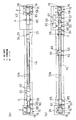
【図2】同移動体使用の搬送設備における平面図で、(a)は後押し経路部、(b)は復帰経路部を示す。
【図3】同移動体使用の搬送設備における後押し経路部を示し、両プラットフォーム下動状態での要部の側面図である。
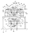
【図4】同移動体使用の搬送設備における後押し経路部を示し、両プラットフォーム下動状態での背面図である。
【図5】同移動体使用の搬送設備における後押し経路部を示し、両プラットフォーム下動状態での要部の平面図である。
【図6】同移動体使用の搬送設備における下動したプラットフォーム部分の一部切り欠き側面図である。
【図7】同移動体使用の搬送設備における上動したプラットフォーム部分の一部切り欠き側面図である。
【図8】同移動体使用の搬送設備におけるプラットフォームの固定手段部分の一部切り欠き正面図である。
【図9】同移動体使用の搬送設備における後押し経路部を示し、両プラットフォーム上動状態での要部の側面図である。
【図10】同移動体使用の搬送設備における後押し経路部を示し、片側プラットフォーム上動状態での要部の側面図である。
【符号の説明】
1 循環経路
1A 後押し経路部
1B 復帰経路部
1C 昇降経路部
1D 昇降経路部
2 積み込み部
3 卸し部
4 送り装置
5 制動装置
6 高速送り装置
7 制動装置
12A レール
12B レール
13A カムレール
13B カムレール
15 移載手段
20 移動体
24 当接部
25 当接部
26A プラットフォーム
26B プラットフォーム
28a 揺動軸心
30 当接部
31 当接部
33 固定手段
35 被係止孔(被係止部)
36 被係止孔(被係止部)
38 係止ピン(係止体)
40 受動面
41 受動面
43 支持装置
43A 前輪支持部
43B 後輪支持部
47 車輪受け体
50 送り込み装置
51 引き出し装置
52 減速装置
53 加速装置
58 送り出し装置
59 ストレージ部
65 ローラ
70 二輪車(被搬送物)[0001]
BACKGROUND OF THE INVENTION
The present invention uses, for example, a moving body that is used to move a non-drive-type moving body that can run on the floor side on a fixed circulation path and transport an object supported by the moving body. It relates to the transport equipment.
[0002]
[Prior art]
2. Description of the Related Art Conventionally, a configuration as disclosed in, for example, Japanese Patent Application Laid-Open No. 2-209309 is provided as a non-driving type moving body that moves on a fixed path.
In this conventional configuration, the movable body conveying device is provided on the upper side of a fixed path on which the movable body can travel, and the brake device is provided on the lower side. The movable body conveying device is composed of a pair of left and right feed rollers that can be brought into contact with the side surface of the movable body, and a rotational drive device that is interlocked with these feed rollers. The brake device is composed of a pair of left and right brake rollers that can be brought into contact with the side surface of the movable body, and a torque motor that applies a reverse feed rotational force to the brake rollers.
[0003]
According to such a conventional configuration, a large driving force is given to the movable body by forcibly rotating the feed rollers that are in contact with both side surfaces of the movable body by the rotation driving device. It can move on a certain route. At that time, the movable body pushes and moves the movable body group which has stopped in advance.
In the lower part of the fixed path, the reversely rotated brake roller is in contact with both side surfaces of the movable body, so that a propulsive force in the reverse conveyance direction acts on the movable body, where the feed rotational force is reversed. Since it is larger than the feed rotation force, the brake roller is rotated to the feed rotation side according to the difference. As a result, the lower movable body is moved in a state of receiving a braking action, and thus the movable body group is moved in a densely pushed state without generating a gap between the front and rear ends.
[0004]
[Problems to be solved by the invention]
According to the above-described conventional configuration, when performing various operations by the worker on the transported object transported by the movable body, the worker must perform the transported transported object from the floor side. In addition, various operations cannot be easily performed. To cope with this, it is conceivable that the main body shape of the movable body is increased with respect to the object to be conveyed, and an operator gets on the main body to perform various operations on the object to be conveyed. However, in this case, the total length of the movable body becomes long, and the path length becomes long when moving the desired number of units in various work path parts while transporting short objects to be transported. This causes problems such as widening.
[0005]
The object of the present invention is that the moving body group can be moved in a dense boosted state without creating a gap between the front and rear ends, but the moving bodies are both long that an operator can get on. The object of the present invention is to provide a transport facility using a moving body that can be switched between a long form for a transported object and a short form for a short transported object.
[0006]
[Means for Solving the Problems]
In order to achieve the above-described object, the transportation facility using the moving body according to
[0007]
Therefore, according to the first aspect of the present invention, the movable body can be moved along the circulation path, the boost path section, the lifting path section, the return path section, and the lifting path section. In the boost path section, the moving body is applied to the moving body by the feeding device on the upper side, and the moving body is applied to the moving body by the braking device on the lower side, so that the moving body group is spaced between the front and rear ends. It is possible to move in a dense boosting state without generating any.
[0008]
At that time, by moving the platform horizontally, the movable body group is formed into a long form for a long object that can be carried by an operator, and the densely boosted without creating a gap between the front and rear ends. Can move in state. Also, the platform is moved down vertically, and the front and rear moving bodies are brought into contact with each other by filling the space equivalent to the platform space. As described above, the movement can be performed in a dense boosted state without generating a gap between the front and rear ends.
[0009]
According to a second aspect of the present invention, there is provided a transporting facility using a moving body, wherein the platform is provided on the front and rear ends of the moving body so as to be able to swing up and down. It is characterized in that it can be fixed by moving up to the shape.
Therefore, according to the invention of
[0010]
According to a third aspect of the present invention, there is provided a transporting facility using a moving body in the configuration according to the first or second aspect, wherein a passive surface is formed across the side surfaces of the moving body and the platform. Is provided with a roller that can contact the passive surface.
Therefore, according to the third aspect of the present invention, a moving force can be applied to the moving body by bringing the roller of the feeding device into contact with the passive surface of the moving body or the platform, and the roller of the braking device can be passively applied to the moving body or the platform. A braking force can be applied to the moving body by contacting the surface.
[0011]
DETAILED DESCRIPTION OF THE INVENTION
Embodiments of the present invention will be described below with reference to the drawings.
In FIG. 1 and FIG. 2, the
[0012]
The
1 to 5, a pair of left and
[0013]
The moving
[0014]
In FIGS. 1 to 8, long plate-
[0015]
As a result, the
[0016]
Further, when both
[0017]
The
The fixing means 33 is positioned at two locations on the arc centering on the plate-like locked
[0018]
The left and right side surfaces of the
On the upper side of the moving
[0019]
The
[0020]
A pair of
[0021]
A
[0022]
The
[0023]
The
[0024]
The high-
[0025]
The
[0026]
The operation in the above embodiment will be described below.
First, the overall flow will be described. At this time, it is assumed that the
[0027]
As shown in FIGS. 1 and 2, the empty moving
[0028]
At this time, the
[0029]
At that time, as shown in FIG. 3, the
[0030]
In this way, a braking force is applied by the
[0031]
As a result, the
[0032]
As a result, the moving
[0033]
In this way, various operations can be performed on the two-wheeled
[0034]
That is, in the boosting
Further, when the moving
[0035]
The moving
[0036]
As a result, the
[0037]
Then, the moving
[0038]
Next, after braking in the
Next, a state in which both
[0039]
As a result, the
Accordingly, in the
[0040]
As a result, the moving
[0041]
Next, a state in which only the
[0042]
Accordingly, in the
[0043]
As a result, in the
[0044]
In the embodiment described above, the
In the above-described embodiment, the friction roller type is adopted as the
[0045]
In the above-described embodiment, the
[0046]
In the above-described embodiment, the locked
In the embodiment described above, the
[0047]
【The invention's effect】
According to the first aspect of the present invention described above, the moving body can move in the circulation path, the boost path section, the lift path section, the return path section, and the lift path section, and in the boost path section, on the upper side, the feeding device By applying a moving force to the moving body by applying a braking force to the moving body by a braking device on the lower side, the moving body group is moved in a dense boosted state without creating a gap between the front and rear ends. it can.
[0048]
At that time, by moving the platform horizontally, the movable body group is formed into a long form for a long object that can be carried by an operator, and the densely boosted without creating a gap between the front and rear ends. It is possible to move in a state, and it is possible to easily perform various operations when an operator gets on. Also, the platform is moved down vertically, and the front and rear moving bodies are brought into contact with each other by filling the space equivalent to the platform space. It is possible to move in a dense boosted state without creating a gap between the front and rear ends, and in various work route parts that do not depend on the operator, the route length can be shortened when moving the desired number of equipment. The entire installation space can be reduced.
[0049]
According to the second aspect of the present invention described above, the moving body has a long form in which both platforms are moved up horizontally, one platform is moved up horizontally, and the other platform is moved vertically. It is possible to arbitrarily and easily switch between an intermediate scale form moved down and a short form form where both platforms are moved vertically down, and each form can be fixed and held firmly.
[0050]
According to the third aspect of the present invention described above, a moving force can be applied to the moving body by bringing the roller of the feeding device into contact with the passive surface of the moving body or the platform, and the roller of the braking device is moved to the moving body or the platform. By abutting against the passive surface, it is possible to apply a braking force to the moving body, and thus it is possible to suitably perform a dense pushing movement in the pushing path portion.
[Brief description of the drawings]
FIG. 1 shows an example of an embodiment of the present invention and is a side view of a transport facility using a moving body.
FIGS. 2A and 2B are plan views of a transport facility using the moving body, in which FIG. 2A shows a boost path section and FIG. 2B shows a return path section;
FIG. 3 is a side view of a main part in a state where both platforms are moved downwards, showing a boosting path part in the transport facility using the moving body.
FIG. 4 is a rear view showing a push path portion in a transport facility using the same moving body, in a state where both platforms are moved downward.
FIG. 5 is a plan view of a main part in a state where both platforms are moved downwards, showing a boosting path portion in the transport facility using the moving body.
FIG. 6 is a partially cutaway side view of the platform portion that has moved down in the transport facility using the moving body.
FIG. 7 is a partially cutaway side view of the platform portion that has moved upward in the transport facility using the same moving body.
FIG. 8 is a partially cutaway front view of a fixing means portion of a platform in the transport facility using the moving body.
FIG. 9 is a side view of a main part in a moving state on both platforms, showing a boost path portion in the transport facility using the same moving body.
FIG. 10 is a side view of a main part in a moving state on a one-side platform, showing a boosting path portion in the transport facility using the moving body.
[Explanation of symbols]
1 Circulation route
1A Boosting path
1B Return path section
1C Lifting path part
1D elevator path
2 Loading section
3 Wholesale Department
4 Feeder
5 Braking device
6 High-speed feeder
7 Braking device
12A rail
12B rail
13A Cam rail
13B Cam rail
15 Transfer means
20 Mobile
24 Contact part
25 Contact part
26A platform
26B platform
28a Oscillation axis
30 Contact part
31 Contact part
33 Fixing means
35 Locked hole (locked part)
36 Locked hole (Locked part)
38 Locking pin (locking body)
40 Passive surface
41 Passive surface
43 Supporting device
43A Front wheel support
43B Rear wheel support
47 Wheel receiver
50 Feeder
51 Drawer device
52 Reduction gear
53 Accelerator
58 Delivery device
59 Storage Department
65 Laura
70 Motorcycle (conveyed object)
Claims (3)
Priority Applications (1)
| Application Number | Priority Date | Filing Date | Title |
|---|---|---|---|
| JP05485199A JP4222672B2 (en) | 1999-03-03 | 1999-03-03 | Transportation equipment using mobile objects |
Applications Claiming Priority (1)
| Application Number | Priority Date | Filing Date | Title |
|---|---|---|---|
| JP05485199A JP4222672B2 (en) | 1999-03-03 | 1999-03-03 | Transportation equipment using mobile objects |
Publications (2)
| Publication Number | Publication Date |
|---|---|
| JP2000255422A JP2000255422A (en) | 2000-09-19 |
| JP4222672B2 true JP4222672B2 (en) | 2009-02-12 |
Family
ID=12982110
Family Applications (1)
| Application Number | Title | Priority Date | Filing Date |
|---|---|---|---|
| JP05485199A Expired - Fee Related JP4222672B2 (en) | 1999-03-03 | 1999-03-03 | Transportation equipment using mobile objects |
Country Status (1)
| Country | Link |
|---|---|
| JP (1) | JP4222672B2 (en) |
Cited By (1)
| Publication number | Priority date | Publication date | Assignee | Title |
|---|---|---|---|---|
| KR102843702B1 (en) * | 2024-09-13 | 2025-08-07 | (주)골든테크 | Lateral-driven skid conveyor system |
Families Citing this family (6)
| Publication number | Priority date | Publication date | Assignee | Title |
|---|---|---|---|---|
| US7500435B2 (en) * | 2006-03-31 | 2009-03-10 | Honda Motor Co., Ltd. | Friction drive system and method for palletized conveyor |
| WO2009075146A1 (en) * | 2007-12-11 | 2009-06-18 | Toyota Shatai Kabushiki Kaisha | Workpiece conveyor |
| JP5597965B2 (en) * | 2009-10-15 | 2014-10-01 | 中西金属工業株式会社 | Cart carrier |
| JP6061204B2 (en) * | 2014-03-28 | 2017-01-18 | 株式会社ダイフク | Friction drive transfer device using transfer carriage |
| CN108298263B (en) * | 2017-12-29 | 2019-04-12 | 华中科技大学 | A kind of heavy duty non-hopping formula stepping transmission device |
| CN117068989A (en) * | 2023-09-25 | 2023-11-17 | 中国汽车工业工程有限公司 | A kind of mechanical lifting skateboard |
-
1999
- 1999-03-03 JP JP05485199A patent/JP4222672B2/en not_active Expired - Fee Related
Cited By (1)
| Publication number | Priority date | Publication date | Assignee | Title |
|---|---|---|---|---|
| KR102843702B1 (en) * | 2024-09-13 | 2025-08-07 | (주)골든테크 | Lateral-driven skid conveyor system |
Also Published As
| Publication number | Publication date |
|---|---|
| JP2000255422A (en) | 2000-09-19 |
Similar Documents
| Publication | Publication Date | Title |
|---|---|---|
| EP1785224B1 (en) | Work transport apparatus and method | |
| JP6501078B2 (en) | Conveying equipment using traveling vehicle | |
| JP4222672B2 (en) | Transportation equipment using mobile objects | |
| JP3043157B2 (en) | Transport equipment using carts | |
| JP3929195B2 (en) | Transportation equipment using mobile objects | |
| CN110424798B (en) | Automobile carrying device | |
| JP2019137513A (en) | Transport work facility | |
| JPH04306162A (en) | Pallet conveyance facilities | |
| JPH05170325A (en) | Conveying equipment using movable body | |
| JP3929196B2 (en) | Transportation equipment using mobile objects | |
| JPH061419A (en) | Movable body carrier device | |
| JPH1135112A (en) | Putting-on-shelf device, putting-on-shelf method to house carrying material in shelf and method of setting receiving conveyor to receiving height in putting-on-shelf device | |
| JP2000007145A (en) | Stopper operating device in transfer device | |
| JP2014005114A (en) | Transporting device | |
| JP3544867B2 (en) | Transport equipment using moving objects | |
| JPH05170324A (en) | Conveying equipment using movable body | |
| JP3116930B2 (en) | Transport equipment using moving objects | |
| JP2819949B2 (en) | Transfer equipment using hangers | |
| JP3900750B2 (en) | Transportation equipment using mobile objects | |
| JP3105172B2 (en) | Supply device in transfer machine | |
| JPH09175642A (en) | Conveyance facility which uses movable body | |
| JP2741282B2 (en) | Truck transport device | |
| JP4118066B2 (en) | Transportation equipment using moving objects | |
| JP3780774B2 (en) | Transportation equipment using mobile objects | |
| JP3925009B2 (en) | Transportation equipment using mobile objects |
Legal Events
| Date | Code | Title | Description |
|---|---|---|---|
| A977 | Report on retrieval |
Free format text: JAPANESE INTERMEDIATE CODE: A971007 Effective date: 20070126 |
|
| A131 | Notification of reasons for refusal |
Free format text: JAPANESE INTERMEDIATE CODE: A131 Effective date: 20070206 |
|
| A521 | Written amendment |
Free format text: JAPANESE INTERMEDIATE CODE: A523 Effective date: 20070328 |
|
| A131 | Notification of reasons for refusal |
Free format text: JAPANESE INTERMEDIATE CODE: A131 Effective date: 20071127 |
|
| A521 | Written amendment |
Free format text: JAPANESE INTERMEDIATE CODE: A523 Effective date: 20080118 |
|
| TRDD | Decision of grant or rejection written | ||
| A01 | Written decision to grant a patent or to grant a registration (utility model) |
Free format text: JAPANESE INTERMEDIATE CODE: A01 Effective date: 20081021 |
|
| A01 | Written decision to grant a patent or to grant a registration (utility model) |
Free format text: JAPANESE INTERMEDIATE CODE: A01 |
|
| A61 | First payment of annual fees (during grant procedure) |
Free format text: JAPANESE INTERMEDIATE CODE: A61 Effective date: 20081118 |
|
| R150 | Certificate of patent or registration of utility model |
Free format text: JAPANESE INTERMEDIATE CODE: R150 |
|
| FPAY | Renewal fee payment (event date is renewal date of database) |
Free format text: PAYMENT UNTIL: 20111128 Year of fee payment: 3 |
|
| FPAY | Renewal fee payment (event date is renewal date of database) |
Free format text: PAYMENT UNTIL: 20121128 Year of fee payment: 4 |
|
| FPAY | Renewal fee payment (event date is renewal date of database) |
Free format text: PAYMENT UNTIL: 20131128 Year of fee payment: 5 |
|
| FPAY | Renewal fee payment (event date is renewal date of database) |
Free format text: PAYMENT UNTIL: 20131128 Year of fee payment: 5 |
|
| FPAY | Renewal fee payment (event date is renewal date of database) |
Free format text: PAYMENT UNTIL: 20141128 Year of fee payment: 6 |
|
| R250 | Receipt of annual fees |
Free format text: JAPANESE INTERMEDIATE CODE: R250 |
|
| S111 | Request for change of ownership or part of ownership |
Free format text: JAPANESE INTERMEDIATE CODE: R313117 |
|
| R350 | Written notification of registration of transfer |
Free format text: JAPANESE INTERMEDIATE CODE: R350 |
|
| R250 | Receipt of annual fees |
Free format text: JAPANESE INTERMEDIATE CODE: R250 |
|
| R250 | Receipt of annual fees |
Free format text: JAPANESE INTERMEDIATE CODE: R250 |
|
| R250 | Receipt of annual fees |
Free format text: JAPANESE INTERMEDIATE CODE: R250 |
|
| LAPS | Cancellation because of no payment of annual fees |