JP4222633B2 - Method for producing a synthetic bone substitute having controlled porosity - Google Patents
Method for producing a synthetic bone substitute having controlled porosity Download PDFInfo
- Publication number
- JP4222633B2 JP4222633B2 JP53387598A JP53387598A JP4222633B2 JP 4222633 B2 JP4222633 B2 JP 4222633B2 JP 53387598 A JP53387598 A JP 53387598A JP 53387598 A JP53387598 A JP 53387598A JP 4222633 B2 JP4222633 B2 JP 4222633B2
- Authority
- JP
- Japan
- Prior art keywords
- particles
- organic compound
- temperature
- manufacturing
- ceramic
- Prior art date
- Legal status (The legal status is an assumption and is not a legal conclusion. Google has not performed a legal analysis and makes no representation as to the accuracy of the status listed.)
- Expired - Fee Related
Links
Images


Classifications
-
- A—HUMAN NECESSITIES
- A61—MEDICAL OR VETERINARY SCIENCE; HYGIENE
- A61F—FILTERS IMPLANTABLE INTO BLOOD VESSELS; PROSTHESES; DEVICES PROVIDING PATENCY TO, OR PREVENTING COLLAPSING OF, TUBULAR STRUCTURES OF THE BODY, e.g. STENTS; ORTHOPAEDIC, NURSING OR CONTRACEPTIVE DEVICES; FOMENTATION; TREATMENT OR PROTECTION OF EYES OR EARS; BANDAGES, DRESSINGS OR ABSORBENT PADS; FIRST-AID KITS
- A61F2/00—Filters implantable into blood vessels; Prostheses, i.e. artificial substitutes or replacements for parts of the body; Appliances for connecting them with the body; Devices providing patency to, or preventing collapsing of, tubular structures of the body, e.g. stents
- A61F2/02—Prostheses implantable into the body
- A61F2/28—Bones
-
- A—HUMAN NECESSITIES
- A61—MEDICAL OR VETERINARY SCIENCE; HYGIENE
- A61L—METHODS OR APPARATUS FOR STERILISING MATERIALS OR OBJECTS IN GENERAL; DISINFECTION, STERILISATION OR DEODORISATION OF AIR; CHEMICAL ASPECTS OF BANDAGES, DRESSINGS, ABSORBENT PADS OR SURGICAL ARTICLES; MATERIALS FOR BANDAGES, DRESSINGS, ABSORBENT PADS OR SURGICAL ARTICLES
- A61L27/00—Materials for grafts or prostheses or for coating grafts or prostheses
- A61L27/02—Inorganic materials
- A61L27/12—Phosphorus-containing materials, e.g. apatite
-
- C—CHEMISTRY; METALLURGY
- C04—CEMENTS; CONCRETE; ARTIFICIAL STONE; CERAMICS; REFRACTORIES
- C04B—LIME, MAGNESIA; SLAG; CEMENTS; COMPOSITIONS THEREOF, e.g. MORTARS, CONCRETE OR LIKE BUILDING MATERIALS; ARTIFICIAL STONE; CERAMICS; REFRACTORIES; TREATMENT OF NATURAL STONE
- C04B35/00—Shaped ceramic products characterised by their composition; Ceramics compositions; Processing powders of inorganic compounds preparatory to the manufacturing of ceramic products
- C04B35/01—Shaped ceramic products characterised by their composition; Ceramics compositions; Processing powders of inorganic compounds preparatory to the manufacturing of ceramic products based on oxide ceramics
- C04B35/447—Shaped ceramic products characterised by their composition; Ceramics compositions; Processing powders of inorganic compounds preparatory to the manufacturing of ceramic products based on oxide ceramics based on phosphates, e.g. hydroxyapatite
-
- A—HUMAN NECESSITIES
- A61—MEDICAL OR VETERINARY SCIENCE; HYGIENE
- A61F—FILTERS IMPLANTABLE INTO BLOOD VESSELS; PROSTHESES; DEVICES PROVIDING PATENCY TO, OR PREVENTING COLLAPSING OF, TUBULAR STRUCTURES OF THE BODY, e.g. STENTS; ORTHOPAEDIC, NURSING OR CONTRACEPTIVE DEVICES; FOMENTATION; TREATMENT OR PROTECTION OF EYES OR EARS; BANDAGES, DRESSINGS OR ABSORBENT PADS; FIRST-AID KITS
- A61F2/00—Filters implantable into blood vessels; Prostheses, i.e. artificial substitutes or replacements for parts of the body; Appliances for connecting them with the body; Devices providing patency to, or preventing collapsing of, tubular structures of the body, e.g. stents
- A61F2/02—Prostheses implantable into the body
- A61F2/30—Joints
- A61F2/3094—Designing or manufacturing processes
-
- A—HUMAN NECESSITIES
- A61—MEDICAL OR VETERINARY SCIENCE; HYGIENE
- A61F—FILTERS IMPLANTABLE INTO BLOOD VESSELS; PROSTHESES; DEVICES PROVIDING PATENCY TO, OR PREVENTING COLLAPSING OF, TUBULAR STRUCTURES OF THE BODY, e.g. STENTS; ORTHOPAEDIC, NURSING OR CONTRACEPTIVE DEVICES; FOMENTATION; TREATMENT OR PROTECTION OF EYES OR EARS; BANDAGES, DRESSINGS OR ABSORBENT PADS; FIRST-AID KITS
- A61F2/00—Filters implantable into blood vessels; Prostheses, i.e. artificial substitutes or replacements for parts of the body; Appliances for connecting them with the body; Devices providing patency to, or preventing collapsing of, tubular structures of the body, e.g. stents
- A61F2/02—Prostheses implantable into the body
- A61F2/30—Joints
- A61F2/38—Joints for elbows or knees
- A61F2/389—Tibial components
-
- A—HUMAN NECESSITIES
- A61—MEDICAL OR VETERINARY SCIENCE; HYGIENE
- A61F—FILTERS IMPLANTABLE INTO BLOOD VESSELS; PROSTHESES; DEVICES PROVIDING PATENCY TO, OR PREVENTING COLLAPSING OF, TUBULAR STRUCTURES OF THE BODY, e.g. STENTS; ORTHOPAEDIC, NURSING OR CONTRACEPTIVE DEVICES; FOMENTATION; TREATMENT OR PROTECTION OF EYES OR EARS; BANDAGES, DRESSINGS OR ABSORBENT PADS; FIRST-AID KITS
- A61F2/00—Filters implantable into blood vessels; Prostheses, i.e. artificial substitutes or replacements for parts of the body; Appliances for connecting them with the body; Devices providing patency to, or preventing collapsing of, tubular structures of the body, e.g. stents
- A61F2/02—Prostheses implantable into the body
- A61F2/30—Joints
- A61F2002/30001—Additional features of subject-matter classified in A61F2/28, A61F2/30 and subgroups thereof
- A61F2002/30003—Material related properties of the prosthesis or of a coating on the prosthesis
- A61F2002/30004—Material related properties of the prosthesis or of a coating on the prosthesis the prosthesis being made from materials having different values of a given property at different locations within the same prosthesis
- A61F2002/30011—Material related properties of the prosthesis or of a coating on the prosthesis the prosthesis being made from materials having different values of a given property at different locations within the same prosthesis differing in porosity
-
- A—HUMAN NECESSITIES
- A61—MEDICAL OR VETERINARY SCIENCE; HYGIENE
- A61F—FILTERS IMPLANTABLE INTO BLOOD VESSELS; PROSTHESES; DEVICES PROVIDING PATENCY TO, OR PREVENTING COLLAPSING OF, TUBULAR STRUCTURES OF THE BODY, e.g. STENTS; ORTHOPAEDIC, NURSING OR CONTRACEPTIVE DEVICES; FOMENTATION; TREATMENT OR PROTECTION OF EYES OR EARS; BANDAGES, DRESSINGS OR ABSORBENT PADS; FIRST-AID KITS
- A61F2/00—Filters implantable into blood vessels; Prostheses, i.e. artificial substitutes or replacements for parts of the body; Appliances for connecting them with the body; Devices providing patency to, or preventing collapsing of, tubular structures of the body, e.g. stents
- A61F2/02—Prostheses implantable into the body
- A61F2/30—Joints
- A61F2002/30001—Additional features of subject-matter classified in A61F2/28, A61F2/30 and subgroups thereof
- A61F2002/30108—Shapes
- A61F2002/30199—Three-dimensional shapes
- A61F2002/30205—Three-dimensional shapes conical
- A61F2002/3021—Three-dimensional shapes conical frustoconical
-
- A—HUMAN NECESSITIES
- A61—MEDICAL OR VETERINARY SCIENCE; HYGIENE
- A61F—FILTERS IMPLANTABLE INTO BLOOD VESSELS; PROSTHESES; DEVICES PROVIDING PATENCY TO, OR PREVENTING COLLAPSING OF, TUBULAR STRUCTURES OF THE BODY, e.g. STENTS; ORTHOPAEDIC, NURSING OR CONTRACEPTIVE DEVICES; FOMENTATION; TREATMENT OR PROTECTION OF EYES OR EARS; BANDAGES, DRESSINGS OR ABSORBENT PADS; FIRST-AID KITS
- A61F2/00—Filters implantable into blood vessels; Prostheses, i.e. artificial substitutes or replacements for parts of the body; Appliances for connecting them with the body; Devices providing patency to, or preventing collapsing of, tubular structures of the body, e.g. stents
- A61F2/02—Prostheses implantable into the body
- A61F2/30—Joints
- A61F2002/30001—Additional features of subject-matter classified in A61F2/28, A61F2/30 and subgroups thereof
- A61F2002/30108—Shapes
- A61F2002/30199—Three-dimensional shapes
- A61F2002/30205—Three-dimensional shapes conical
- A61F2002/30217—Three-dimensional shapes conical hollow cones, e.g. tubular-like cones
-
- A—HUMAN NECESSITIES
- A61—MEDICAL OR VETERINARY SCIENCE; HYGIENE
- A61F—FILTERS IMPLANTABLE INTO BLOOD VESSELS; PROSTHESES; DEVICES PROVIDING PATENCY TO, OR PREVENTING COLLAPSING OF, TUBULAR STRUCTURES OF THE BODY, e.g. STENTS; ORTHOPAEDIC, NURSING OR CONTRACEPTIVE DEVICES; FOMENTATION; TREATMENT OR PROTECTION OF EYES OR EARS; BANDAGES, DRESSINGS OR ABSORBENT PADS; FIRST-AID KITS
- A61F2/00—Filters implantable into blood vessels; Prostheses, i.e. artificial substitutes or replacements for parts of the body; Appliances for connecting them with the body; Devices providing patency to, or preventing collapsing of, tubular structures of the body, e.g. stents
- A61F2/02—Prostheses implantable into the body
- A61F2/30—Joints
- A61F2002/30001—Additional features of subject-matter classified in A61F2/28, A61F2/30 and subgroups thereof
- A61F2002/30108—Shapes
- A61F2002/30199—Three-dimensional shapes
- A61F2002/30224—Three-dimensional shapes cylindrical
- A61F2002/30235—Three-dimensional shapes cylindrical tubular, e.g. sleeves
-
- A—HUMAN NECESSITIES
- A61—MEDICAL OR VETERINARY SCIENCE; HYGIENE
- A61F—FILTERS IMPLANTABLE INTO BLOOD VESSELS; PROSTHESES; DEVICES PROVIDING PATENCY TO, OR PREVENTING COLLAPSING OF, TUBULAR STRUCTURES OF THE BODY, e.g. STENTS; ORTHOPAEDIC, NURSING OR CONTRACEPTIVE DEVICES; FOMENTATION; TREATMENT OR PROTECTION OF EYES OR EARS; BANDAGES, DRESSINGS OR ABSORBENT PADS; FIRST-AID KITS
- A61F2/00—Filters implantable into blood vessels; Prostheses, i.e. artificial substitutes or replacements for parts of the body; Appliances for connecting them with the body; Devices providing patency to, or preventing collapsing of, tubular structures of the body, e.g. stents
- A61F2/02—Prostheses implantable into the body
- A61F2/30—Joints
- A61F2002/30001—Additional features of subject-matter classified in A61F2/28, A61F2/30 and subgroups thereof
- A61F2002/30108—Shapes
- A61F2002/30199—Three-dimensional shapes
- A61F2002/30261—Three-dimensional shapes parallelepipedal
- A61F2002/30266—Three-dimensional shapes parallelepipedal wedge-shaped parallelepipeds
-
- A—HUMAN NECESSITIES
- A61—MEDICAL OR VETERINARY SCIENCE; HYGIENE
- A61F—FILTERS IMPLANTABLE INTO BLOOD VESSELS; PROSTHESES; DEVICES PROVIDING PATENCY TO, OR PREVENTING COLLAPSING OF, TUBULAR STRUCTURES OF THE BODY, e.g. STENTS; ORTHOPAEDIC, NURSING OR CONTRACEPTIVE DEVICES; FOMENTATION; TREATMENT OR PROTECTION OF EYES OR EARS; BANDAGES, DRESSINGS OR ABSORBENT PADS; FIRST-AID KITS
- A61F2/00—Filters implantable into blood vessels; Prostheses, i.e. artificial substitutes or replacements for parts of the body; Appliances for connecting them with the body; Devices providing patency to, or preventing collapsing of, tubular structures of the body, e.g. stents
- A61F2/02—Prostheses implantable into the body
- A61F2/30—Joints
- A61F2002/30001—Additional features of subject-matter classified in A61F2/28, A61F2/30 and subgroups thereof
- A61F2002/30108—Shapes
- A61F2002/30199—Three-dimensional shapes
- A61F2002/3028—Three-dimensional shapes polyhedral different from parallelepipedal and pyramidal
-
- A—HUMAN NECESSITIES
- A61—MEDICAL OR VETERINARY SCIENCE; HYGIENE
- A61F—FILTERS IMPLANTABLE INTO BLOOD VESSELS; PROSTHESES; DEVICES PROVIDING PATENCY TO, OR PREVENTING COLLAPSING OF, TUBULAR STRUCTURES OF THE BODY, e.g. STENTS; ORTHOPAEDIC, NURSING OR CONTRACEPTIVE DEVICES; FOMENTATION; TREATMENT OR PROTECTION OF EYES OR EARS; BANDAGES, DRESSINGS OR ABSORBENT PADS; FIRST-AID KITS
- A61F2/00—Filters implantable into blood vessels; Prostheses, i.e. artificial substitutes or replacements for parts of the body; Appliances for connecting them with the body; Devices providing patency to, or preventing collapsing of, tubular structures of the body, e.g. stents
- A61F2/02—Prostheses implantable into the body
- A61F2/30—Joints
- A61F2/3094—Designing or manufacturing processes
- A61F2/30942—Designing or manufacturing processes for designing or making customized prostheses, e.g. using templates, CT or NMR scans, finite-element analysis or CAD-CAM techniques
- A61F2002/30957—Designing or manufacturing processes for designing or making customized prostheses, e.g. using templates, CT or NMR scans, finite-element analysis or CAD-CAM techniques using a positive or a negative model, e.g. moulds
-
- A—HUMAN NECESSITIES
- A61—MEDICAL OR VETERINARY SCIENCE; HYGIENE
- A61F—FILTERS IMPLANTABLE INTO BLOOD VESSELS; PROSTHESES; DEVICES PROVIDING PATENCY TO, OR PREVENTING COLLAPSING OF, TUBULAR STRUCTURES OF THE BODY, e.g. STENTS; ORTHOPAEDIC, NURSING OR CONTRACEPTIVE DEVICES; FOMENTATION; TREATMENT OR PROTECTION OF EYES OR EARS; BANDAGES, DRESSINGS OR ABSORBENT PADS; FIRST-AID KITS
- A61F2/00—Filters implantable into blood vessels; Prostheses, i.e. artificial substitutes or replacements for parts of the body; Appliances for connecting them with the body; Devices providing patency to, or preventing collapsing of, tubular structures of the body, e.g. stents
- A61F2/02—Prostheses implantable into the body
- A61F2/30—Joints
- A61F2/3094—Designing or manufacturing processes
- A61F2002/30968—Sintering
-
- A—HUMAN NECESSITIES
- A61—MEDICAL OR VETERINARY SCIENCE; HYGIENE
- A61F—FILTERS IMPLANTABLE INTO BLOOD VESSELS; PROSTHESES; DEVICES PROVIDING PATENCY TO, OR PREVENTING COLLAPSING OF, TUBULAR STRUCTURES OF THE BODY, e.g. STENTS; ORTHOPAEDIC, NURSING OR CONTRACEPTIVE DEVICES; FOMENTATION; TREATMENT OR PROTECTION OF EYES OR EARS; BANDAGES, DRESSINGS OR ABSORBENT PADS; FIRST-AID KITS
- A61F2230/00—Geometry of prostheses classified in groups A61F2/00 - A61F2/26 or A61F2/82 or A61F9/00 or A61F11/00 or subgroups thereof
- A61F2230/0063—Three-dimensional shapes
- A61F2230/0067—Three-dimensional shapes conical
-
- A—HUMAN NECESSITIES
- A61—MEDICAL OR VETERINARY SCIENCE; HYGIENE
- A61F—FILTERS IMPLANTABLE INTO BLOOD VESSELS; PROSTHESES; DEVICES PROVIDING PATENCY TO, OR PREVENTING COLLAPSING OF, TUBULAR STRUCTURES OF THE BODY, e.g. STENTS; ORTHOPAEDIC, NURSING OR CONTRACEPTIVE DEVICES; FOMENTATION; TREATMENT OR PROTECTION OF EYES OR EARS; BANDAGES, DRESSINGS OR ABSORBENT PADS; FIRST-AID KITS
- A61F2230/00—Geometry of prostheses classified in groups A61F2/00 - A61F2/26 or A61F2/82 or A61F9/00 or A61F11/00 or subgroups thereof
- A61F2230/0063—Three-dimensional shapes
- A61F2230/0069—Three-dimensional shapes cylindrical
-
- A—HUMAN NECESSITIES
- A61—MEDICAL OR VETERINARY SCIENCE; HYGIENE
- A61F—FILTERS IMPLANTABLE INTO BLOOD VESSELS; PROSTHESES; DEVICES PROVIDING PATENCY TO, OR PREVENTING COLLAPSING OF, TUBULAR STRUCTURES OF THE BODY, e.g. STENTS; ORTHOPAEDIC, NURSING OR CONTRACEPTIVE DEVICES; FOMENTATION; TREATMENT OR PROTECTION OF EYES OR EARS; BANDAGES, DRESSINGS OR ABSORBENT PADS; FIRST-AID KITS
- A61F2230/00—Geometry of prostheses classified in groups A61F2/00 - A61F2/26 or A61F2/82 or A61F9/00 or A61F11/00 or subgroups thereof
- A61F2230/0063—Three-dimensional shapes
- A61F2230/0082—Three-dimensional shapes parallelepipedal
-
- A—HUMAN NECESSITIES
- A61—MEDICAL OR VETERINARY SCIENCE; HYGIENE
- A61F—FILTERS IMPLANTABLE INTO BLOOD VESSELS; PROSTHESES; DEVICES PROVIDING PATENCY TO, OR PREVENTING COLLAPSING OF, TUBULAR STRUCTURES OF THE BODY, e.g. STENTS; ORTHOPAEDIC, NURSING OR CONTRACEPTIVE DEVICES; FOMENTATION; TREATMENT OR PROTECTION OF EYES OR EARS; BANDAGES, DRESSINGS OR ABSORBENT PADS; FIRST-AID KITS
- A61F2250/00—Special features of prostheses classified in groups A61F2/00 - A61F2/26 or A61F2/82 or A61F9/00 or A61F11/00 or subgroups thereof
- A61F2250/0014—Special features of prostheses classified in groups A61F2/00 - A61F2/26 or A61F2/82 or A61F9/00 or A61F11/00 or subgroups thereof having different values of a given property or geometrical feature, e.g. mechanical property or material property, at different locations within the same prosthesis
- A61F2250/0023—Special features of prostheses classified in groups A61F2/00 - A61F2/26 or A61F2/82 or A61F9/00 or A61F11/00 or subgroups thereof having different values of a given property or geometrical feature, e.g. mechanical property or material property, at different locations within the same prosthesis differing in porosity
-
- A—HUMAN NECESSITIES
- A61—MEDICAL OR VETERINARY SCIENCE; HYGIENE
- A61F—FILTERS IMPLANTABLE INTO BLOOD VESSELS; PROSTHESES; DEVICES PROVIDING PATENCY TO, OR PREVENTING COLLAPSING OF, TUBULAR STRUCTURES OF THE BODY, e.g. STENTS; ORTHOPAEDIC, NURSING OR CONTRACEPTIVE DEVICES; FOMENTATION; TREATMENT OR PROTECTION OF EYES OR EARS; BANDAGES, DRESSINGS OR ABSORBENT PADS; FIRST-AID KITS
- A61F2310/00—Prostheses classified in A61F2/28 or A61F2/30 - A61F2/44 being constructed from or coated with a particular material
- A61F2310/00005—The prosthesis being constructed from a particular material
- A61F2310/00179—Ceramics or ceramic-like structures
- A61F2310/00293—Ceramics or ceramic-like structures containing a phosphorus-containing compound, e.g. apatite
-
- A—HUMAN NECESSITIES
- A61—MEDICAL OR VETERINARY SCIENCE; HYGIENE
- A61F—FILTERS IMPLANTABLE INTO BLOOD VESSELS; PROSTHESES; DEVICES PROVIDING PATENCY TO, OR PREVENTING COLLAPSING OF, TUBULAR STRUCTURES OF THE BODY, e.g. STENTS; ORTHOPAEDIC, NURSING OR CONTRACEPTIVE DEVICES; FOMENTATION; TREATMENT OR PROTECTION OF EYES OR EARS; BANDAGES, DRESSINGS OR ABSORBENT PADS; FIRST-AID KITS
- A61F2310/00—Prostheses classified in A61F2/28 or A61F2/30 - A61F2/44 being constructed from or coated with a particular material
- A61F2310/00005—The prosthesis being constructed from a particular material
- A61F2310/00353—Bone cement, e.g. polymethylmethacrylate or PMMA
-
- Y—GENERAL TAGGING OF NEW TECHNOLOGICAL DEVELOPMENTS; GENERAL TAGGING OF CROSS-SECTIONAL TECHNOLOGIES SPANNING OVER SEVERAL SECTIONS OF THE IPC; TECHNICAL SUBJECTS COVERED BY FORMER USPC CROSS-REFERENCE ART COLLECTIONS [XRACs] AND DIGESTS
- Y10—TECHNICAL SUBJECTS COVERED BY FORMER USPC
- Y10S—TECHNICAL SUBJECTS COVERED BY FORMER USPC CROSS-REFERENCE ART COLLECTIONS [XRACs] AND DIGESTS
- Y10S623/00—Prosthesis, i.e. artificial body members, parts thereof, or aids and accessories therefor
- Y10S623/92—Method or apparatus for preparing or treating prosthetic
- Y10S623/923—Bone
-
- Y—GENERAL TAGGING OF NEW TECHNOLOGICAL DEVELOPMENTS; GENERAL TAGGING OF CROSS-SECTIONAL TECHNOLOGIES SPANNING OVER SEVERAL SECTIONS OF THE IPC; TECHNICAL SUBJECTS COVERED BY FORMER USPC CROSS-REFERENCE ART COLLECTIONS [XRACs] AND DIGESTS
- Y10—TECHNICAL SUBJECTS COVERED BY FORMER USPC
- Y10S—TECHNICAL SUBJECTS COVERED BY FORMER USPC CROSS-REFERENCE ART COLLECTIONS [XRACs] AND DIGESTS
- Y10S623/00—Prosthesis, i.e. artificial body members, parts thereof, or aids and accessories therefor
- Y10S623/924—Material characteristic
- Y10S623/926—Synthetic
-
- Y—GENERAL TAGGING OF NEW TECHNOLOGICAL DEVELOPMENTS; GENERAL TAGGING OF CROSS-SECTIONAL TECHNOLOGIES SPANNING OVER SEVERAL SECTIONS OF THE IPC; TECHNICAL SUBJECTS COVERED BY FORMER USPC CROSS-REFERENCE ART COLLECTIONS [XRACs] AND DIGESTS
- Y10—TECHNICAL SUBJECTS COVERED BY FORMER USPC
- Y10T—TECHNICAL SUBJECTS COVERED BY FORMER US CLASSIFICATION
- Y10T428/00—Stock material or miscellaneous articles
- Y10T428/249921—Web or sheet containing structurally defined element or component
- Y10T428/249953—Composite having voids in a component [e.g., porous, cellular, etc.]
- Y10T428/249961—With gradual property change within a component
-
- Y—GENERAL TAGGING OF NEW TECHNOLOGICAL DEVELOPMENTS; GENERAL TAGGING OF CROSS-SECTIONAL TECHNOLOGIES SPANNING OVER SEVERAL SECTIONS OF THE IPC; TECHNICAL SUBJECTS COVERED BY FORMER USPC CROSS-REFERENCE ART COLLECTIONS [XRACs] AND DIGESTS
- Y10—TECHNICAL SUBJECTS COVERED BY FORMER USPC
- Y10T—TECHNICAL SUBJECTS COVERED BY FORMER US CLASSIFICATION
- Y10T428/00—Stock material or miscellaneous articles
- Y10T428/249921—Web or sheet containing structurally defined element or component
- Y10T428/249953—Composite having voids in a component [e.g., porous, cellular, etc.]
- Y10T428/249967—Inorganic matrix in void-containing component
Landscapes
- Health & Medical Sciences (AREA)
- Chemical & Material Sciences (AREA)
- Engineering & Computer Science (AREA)
- Oral & Maxillofacial Surgery (AREA)
- Veterinary Medicine (AREA)
- Ceramic Engineering (AREA)
- Public Health (AREA)
- General Health & Medical Sciences (AREA)
- Animal Behavior & Ethology (AREA)
- Life Sciences & Earth Sciences (AREA)
- Transplantation (AREA)
- Inorganic Chemistry (AREA)
- Cardiology (AREA)
- Epidemiology (AREA)
- Dermatology (AREA)
- Organic Chemistry (AREA)
- Structural Engineering (AREA)
- Materials Engineering (AREA)
- Manufacturing & Machinery (AREA)
- Orthopedic Medicine & Surgery (AREA)
- Medicinal Chemistry (AREA)
- Biomedical Technology (AREA)
- Heart & Thoracic Surgery (AREA)
- Vascular Medicine (AREA)
- Materials For Medical Uses (AREA)
- Compositions Of Oxide Ceramics (AREA)
- Porous Artificial Stone Or Porous Ceramic Products (AREA)
- Manufacture Of Porous Articles, And Recovery And Treatment Of Waste Products (AREA)
- Agricultural Chemicals And Associated Chemicals (AREA)
Abstract
Description
本発明は特に骨の代わりに使用することを意図したマクロポーラスな合成セラミックスの製造方法に関し、このセラミックスは空孔間の相互結合の大きさが制御されており、更に空孔の多孔度及び寸法も制御されている。
従来技術におけるこの種の製造方法はいくつかの欠点がある。
即ち、これらの方法では製品としての多孔性の構造物の完全な制御が不可能、特にマクロポアの寸法と形状、セラミック基体におけるマクロポアの分布、更にマクロポア間の相互結合の寸法の制御が不可能である。
このような制御不可能性により、セラミックスの生物学的効果は減少し、例えばそれを骨の代用品として用いる場合、骨組織の再生が不充分であり、少なくともそれは部分的にしか再生しない。
更に、構造物の再現性が不完全なので、往々にして機械的挙動、特に圧縮時における挙動が不均一となる。
製造方法によっては、空孔形成用の団結粉体に圧力を加えることにより相互結合部位の径を制御することを勧めているものもある。
この種の製造方法では、相互結合部位を効果的に制御すること、即ち均一にしかも再現と調節が容易な方法で制御することは不可能である。
更に、従来の人工セラミック骨の構造不均一性は往々にして不安定な機械的挙動の原因となった。
構造物を完全に制御することはできないので、機械的強度は、特に圧縮時には往々にして低いものである。インプラントにかかる機械的応力を減らしその結果、製造部品の寸法を減少させ最終的にインプラントとそれを固定する骨からなる系の機械的損傷の可能性を低くする必要がある。
以上の従来技術は特に、WO−A−92/06653、DE−A−4,403,509、DE−A−3,123,460及びWO−A−95/32008に開示されている。
従って、本発明の目的は上記の従来技術の欠点を解消することである。
従って、本発明の製造方法の目的は次の通りである。
1)合成セラミックを骨の代用品として用いた場合にセラミックのマクロポア間の相互結合部位を、特に骨細胞が通過できるように、従って生体の中心にまで新しい骨組織が形成されるように、再現可能なかつ調節可能な方法で制御すること、しかもこの制御は均一に、しかも骨代替物の寸法にかかわりなくその中心に達するように行う必要がある。
2)セラミックの多孔度と空隙の寸法を制御すること。
3)生体適合性セラミックをカスタムメードに、即ち所定の寸法と形状に作ること。
この目的を達成するため、本発明は前記したような製造方法であり、次の各工程から順に成る方法を提供する。
a)空孔生成要素の集合体を形成する。
b)制御された融合が該空孔生成要素間に確立されるように、該集合体を熱成形する。
c)該空孔生成要素間の空隙を埋めるように懸濁液で該集合体を含浸する。
d)連絡通路の径が制御されたマクロ多孔性を付与するように、該空孔生成要素を除去する。
詳しくいうと本発明の方法では、熱膨張率の低い空孔生成有機化合物の粒子を容器につめる。該粒子は予め決められた形状を有する。
該粒子同士を密着させ、その結果マクロポア間に相互連絡通路を生成させるため該粒子に対して熱成形処理を行う。
この処理の目的は、有機化合物のガラス転移点を超える作業温度を得て、その結果該化合物をそのゴム状プラトー部に保持することにより該粒子同士を適度に融合させるためである。
粒子間に制御された結合を生成し、ひいてはマクロポア間に将来形成される相互連絡通路を制御するには、熱成形処理の際の時間と温度を調節することが必要である。
もし処理時間を短くしたい場合は他の方法を採用できる。例えば、作業温度を高くする(ただし重合体の分解温度までは高くしない)、又は重合体の基体に(そのガラス転移点を超える温度で)圧力を加えることにより融合生成速度を早めるという方法である。
一たん粒子同士が結合すると、この相互結合した粒子から形成される一体構造物を冷却後引抜き多孔性型に配置する。
次に、水性媒体にリン酸カルシウムの粉末を懸濁させたもので粒子間の空隙を埋めセラミックの補強体を形成する。
型の多孔構造を介して水を除去した後、得られた製品を型からはずし加熱処理を施す。この処理の目的は第一工程で有機化合物を除去して空孔を形成し、その後第二工程でセラミックスの内表面をち密にするためである。
本発明に用いる有機化合物はアクリル樹脂から選ばれ例えばポリメチルメタクリレート(PMMA)、ポリメタクリレート(PMA)、ポリスチレン、ポリエチレン及びこれらの類似物である。
更に、本発明の一実施態様において、該粒子は実質的に球形をしている。
本発明において、リン酸カルシウムはヒドロキシアパタイト(HA)、リン酸三石灰(TCPβ)、これらの類似物又は混合物から選ばれる。
本発明の方法によれば、マクロポア間の相互連絡通路が完全に制御され、空孔の寸法が制御されており、予め決定された数及び面積で空孔が分布しているマクロポーラスな合成セラミックスが製造できる。
更に詳しく述べると本発明の方法によれば、球状の空孔の径を100μmから800μmの間で完全に制御でき、しかも空孔間の相互連絡通路がマクロポア径の0.1から0.8倍の大きさの間に入るよう完全に制御されている。好ましくは空孔径は40μmから640μmの間に制御される。
更に、処理温度、圧力、時間のようなパラメータを制御することにより、空孔間の連絡通路の径を制御できる。
粒子間にくびれを形成するために、重合体をそのガラス転移点を超える温度で粘性流を作るように再分布させることにより、粒子の融合を自在に行うことができ、最終的に形成される連絡通路の完全な制御が可能となる。
実験規模ではあるが、マクロポア間の連絡通路の径が30μmを超えるセラミックスを製造できた。この結果、各粒子サイズのビーズを用いて、製品の粒子間融合、従って最終的な連絡通路の径を正確に調節することができる。なお、前記の2つのパラメータは互いに区別され、独立に調節することができる。
本発明は更に前記の種類のセラミックスを全ての寸法で製造することができる。このセラミックスは小さなものも大きなもの(数cm3)もあり、高い機械的強度を持つ。
更に、本方法によれば、複雑な形状を持ち多孔度が一定又は可変の骨代替物として使えるセラミックスを製造することができる。
最後に、本発明のもう一つの側面は、このようなセラミックスの骨代替物としての利用に関するものである。
本発明のその他の特徴と利点は、添付図面と写真を参照して以下の記載から明らかになるだろう。
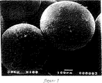
第1図は重合体粒子の融合を示す電子顕微鏡写真である。
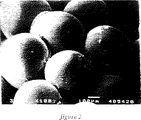
第2図は互いに結合した粒子から形成された一体構造を示す電子顕微鏡写真である。
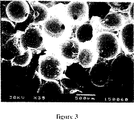
第3図と第4図は500μmの空孔を持ち、連絡通路の径がそれぞれ100μmと200μmであるセラミックスを示す電子顕微鏡写真である。
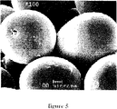
第5図は500℃の熱処理に付した後の粒子を示す電子顕微鏡写真である。
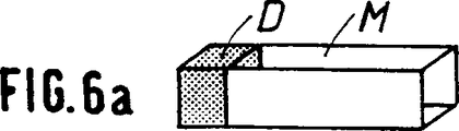
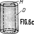
第6aないし第6c図は骨代替物としての使用を示す概略斜視図で端部に機械的補強をしている。
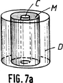
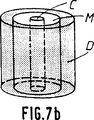
第7a及び第7b図は骨代替物としての使用を示す概略斜視図で筒状の機械的補強をしている。
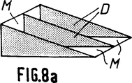
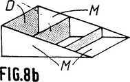
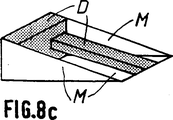
第8aないし第8d図は骨代替物として可能な使用を示す概略斜視図で、特に脛骨切骨手術における使用を示す(第8a図ないし第8c図)。
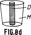
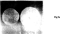
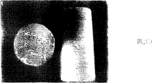
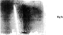
第9aないし第9c図は第8dの代替物としての光学顕微鏡写真でそれぞれ上面、側面及び縦断面を示す。
本発明の一実施態様において、マクロポーラスなセラミックスは容器に充填させたポリメチルメタクリレート(PMMA)のようなアクリル樹脂の粒子を出発物質として製造される。
PMMAの代わりにポリエチレン、ポリメタクリレート又はポリスチレンの粒子を用いることができる。
これらの化合物の共通点は空孔形成特性を有するということである。
一般的には、加熱による劣化を防ぐため熱膨張率の小さい有機化合物であれば全て使用できる。
従って、熱成形可能な熱可塑性樹脂が選ばれる。
更に、具体的な態様においては、加熱処理中の極端な体積増加を防ぐため、少なくとも構造の一部が非晶質の、好ましくは全体が非晶質の重合体を用いる。
最後に、空孔生成要素は低温で分解し残留不純物の量は無視できる程度で、しかも分解生成物は非腐食性でなくてはならない。
PMMAは上記の特性をすべて満足する化合物である。
従って、以下の説明ではPMMA粒子について述べているが、上記の特性を満足する限りその他の化合物はすべて使用できる。
使用するPMMA粒子は実質的に同一、又は異なった寸法のビーズ形状を有する。
後者の場合、所定数の小さな球状粒子を容器の底にまずつめ、その上にこれより大きな球状粒子をのせる。この方法により異なった多孔度のセラミックスを作ることができる。
別法として、容器に複数のビーズを積層する際に徐々に粒径が増加するように充填することができる。この結果、得られたセラミックの多孔度に傾斜を持たせることができる。
球状のPMMA粒子を使えば、粒子を互いに密着させその接触形態を様々に変更でき、形態的に均一な多孔性を得、又セラミックの最終的な空孔体積を制御することができる。
この理由は、PMMA粒子は上記したように変形しないか、してもわずかの変形しかおきないという特徴を持つからである。
この結果、得られた骨代替物中の空孔はもとの粒子と実質的に同一の径を持つ。
具体的な一実施態様において、PMMAビーズは数ミクロンから約850ミクロンの粒径分布を有する。
セラミックス製品中のマクロポアの寸法を制御するためにPMMA粉はあらかじめ機械的分級処理に付す。
比較的せまい粒子サイズのロットを得るようにPMMA粉を異なったメッシュサイズのスクリーンに通す。
選択可能な粒子サイズの巾は0−100μm、100−200μm、200−300μm、400−500μm、500−600μm、600−700μm、又は700−850μmである。
もし必要なら、もっと狭い粒子サイズ、例えば190−200μmを選ぶことができる。
PMMAビーズの一部を中空にして使用することもできる。
使用する粒子の数、形状及び分布は型の形状と目的とするセラミックスにより変化する。
有機化合物の粒子を収容する容器は、少なくとも当該化合物の熱分解温度に耐える必要がある。
アクリル樹脂特にPMMAを使用する本例の場合、この温度は約200℃である。
従って、容器は例えば金属製、セラミック製又は樹脂製のいずれでもよい。
第二工程において、PMMA粒子間の融合を行うためにこれを熱成形処理に付す。
実際、PMMAのような非晶質重合体はそのガラス転移点Tgを超える温度においてゴム状の、稠密度を示す。
尚、PMMAのガラス転移点は約110℃である。
従って、ガラス転移点を超える温度では、重合体はその巨大分子に様々な変更が加えられ、粘性状態に近いゴム状稠密度が得られれる。この結果重合体の成型が容易になる。
このように物質が或る程度の可塑状態にあると、粒子同士の接触の結果、拡散機構により、各々の粒子に含まれる巨大分子の一部が少なくとも部分的に絡みあい互いに融合することになる。
所望の状態が得られたら室温に戻すだけでそれを固定することができる。
この理由は、得られた化合物の粘度は温度が下がると次第に増加するからである。
熱成形方法は一般的に当該粒子を全体的に又はその表面を、有機化合物のガラス転移点を超える温度で均一に加熱することにより行われる。
PMMAの熱成形処理は例えば次の各工程から成る:
1)空の容器をPMMAのガラス転移点より高い温度で、本例の場合約110℃を超す温度で、予備加熱する;
2)該容器にPMMAのビーズを装入する;
3)冷却終了までビーズを成形し融合させる;
4)室温まで冷却する。
別の実施態様では、空の容器を予備加熱するのではなく、ビーズを充填後に容器を加熱することができる。
空孔生成要素の熱成形は再現性を持つのみならず、大表面積(数10平方センチ)かつ大容積(数10立方センチ)の集合体にも又適用できる。
連絡通路の径を制御する方法の効果は本質的に拡散により支配され、融合の良し悪しは温度、時間及び粒子間の接触の度合に依存する。
重合体の成形に最適な温度を決定するには、例えば様々な処理温度に予め加熱した金属容器にPMMAビーズを装入する。
このような温度はガラス転移点より高く各々120℃、150℃、180℃及び200℃である。
以上の試験によれば、ビーズ間の架橋の変化を熱成形時間の関数としてモニタリングすることができる。この分析は走査電顕により行うことができる。
以上の試験はまず粒径分布が500−600μmのPMMAビーズを用いて行う。毎回、一定重さ(5グラム)のビーズを26ミリ径の円筒形の容器に装入する。
処理温度が120℃に等しく、加熱時間が20hを超えた場合、ビーズ同士の凝集は全然みられない。この温度は採用した時間内に重合体ビーズ間に拡散及び十分な架橋を生じさせるには不十分なように思われる。
この粒子間の凝集は150℃で観察される(第5図を参照:そこでは500−600μmの径を有する粒子に対して150℃、16時間の処理を行っている)。
しかし、PMMA粒子間を正確に融合させるには長時間の処理が必要である。16時間処理した試料を走査電顕で分析するとビーズ間の接触領域を観察でき、従って熱成形作業の効果を評価できる。
この接触領域は生体セラミックスのマクロポア間に将来形成される連絡通路に対応する。本例の場合、この接触線は各々独立した状態にあり、その径は100μmと推定される。
試験温度を180℃にした場合、処理時間が短くてもビーズ間に十分な融合を生じさせることができる。
従って、熱成形したPMMA粒子を使えば、ビーズ間に所定数の空隙を有する一体構造が形成される(第1図及び第2図を参照)。
その後この一体構造物を容器から除去し多孔性の型に配置する。
本実施態様ではこの多孔性の型は石こうでできている。
セラミック製、金属製、樹脂製又はこれらの類似物からできた型を用いてもよい。
その後、水性媒体中に懸濁させたリン酸カルシウムを主成分とする濃厚懸濁液によりビーズ間の空隙をうめて含浸させる。
この懸濁液、即ちペーストはヒドロキシアパタイト(HA)又はリン酸三石灰(βTCP)から成る。又は、両者を全量が100%になるよう混合させたものでもよい。
従って、懸濁液は粉末と水とでできており、石こうの多孔性に由来する毛管降下により徐々に一体構造の周りで乾燥していく。
かくしてセラミックスと重合体ビーズの二相混合物である粗(green)生成物が得られる。
本発明の具体的な一実施態様において、多孔性の型はその内部に十分な量のペーストを収容できる容器である。
この容器を使えば、すべての空隙がペーストで完全に埋まるように、一体構造物を連続的に含浸させることができる。含浸は該ペーストが乾くまで行なわれる。この容器はペーストを流延させながら使うことができる。
懸濁液を流延する際、最適脱塊を達成するために解凝工程を行う。
ヒドロキシアパタイトのようなリン酸カルシウムの懸濁液の解凝化はセラミック業界で広く用いられるカルボキシレートタイプのポリ電解質、即ちアンモニウムポリアクリレート(APa)を用いて達成することができる。
所定の条件(APaを0.6%及びpH11)から出発して、HA濃度を82%、84%、86%と増加させて様々な懸濁液を試験した。
上記のペーストの粘度を次に100s-1の速度勾配で測定した。
その結果、固形分82%の懸濁液は比較的低い粘度を有し、PMMA球状粒子中に存在する空隙をすべて埋めることができた。
即ち、固形分濃度の低い懸濁液は特に粘度を下げ、重合体構造への含浸を容易にするのに適している。
得られた粗(green)生成物は次に型からはずす。
次に多孔性を付与するために、粗(green)生成物を低温で熱処理に付す。但し、この熱処理温度は使用する化合物の熱分解温度(本例の場合約200℃)より高くする必要がある。
本実施態様の場合、この処理温度は約300℃よりも低い。
この熱処理により有機物はすべて燃えてなくなり、かくしてビーズが除去されその跡に空隙が生成する。
最後に、生成物の凝集力と剛性を増加させるために、これを1,100℃から1,300℃の間の温度で焼結熱処理に付す。
この結果、制御された連絡通路を有するマクロポーラスなセラミックスが得られ、これは骨の代替物として用いることができる。
第3図と第4図をみれば連絡通路の径が制御され増大しているのがよくわかる(小さな黒点は空隙を示す)。そして多孔度は500μmである。
尚、石こう製の型は単純な形、複雑な形いずれの形も様々にとりうる。
従って、この型は例えば、実質的に平行四辺形又は円柱形の形状をとりうることができ、これも又は単純な形である。
更に、様々な内表面形状の型を用いることにより、複雑な形状のセラミックスを得るようにしてもよい。
実際上、石こう型の形状により最終的なセラミックスの形状が決まるのである。
第6a図から第9c図は得られたセラミックス、従って多孔性型が複雑な形状を有する例を示す。
従って、ち密な部分を設けて骨代替物の特定のゾーンを機械的に補強することができる。
従って、重合体の基体はち密な部分を設けたい部位ではビーズを含まない。
第6a図ないし第6c図では、骨代替物の端部に最もち密な部分Dが位置する。
骨代替物は平行四辺形(第6a図及び第6b図)か又は円筒形(第6c図)である。
ち密な部分をマクロポーラスな部分の間に挿入することもできる(図示せず)。
更に第7a図及び第7b図は円筒形をした骨代替物の例を示しこれはち密な部分D、マクロポーラスな部分M、それに中空部分Cから構成される。
第7a図では、ち密な部分Dが中空部分Cとマクロポーラスな部分Mの間に挿入されており、一方第7b図ではち密な部分が骨代替物の周りに位置している。
最後に、第8a図ないし第8c図は骨代替物が複雑な形状、即ち「くさび」形をしている場合を示す。ここではち密な部分又はマイクロポーラスな部分がDで示され、マイクロポーラスな部分がMで示される。
上記の実施態様において、部分Mは部分Dの間に挿入されている。
このような骨代替物は例えば脛骨切骨手術に利用することができる。
第8d図は第9a図ないし第9c図と同様に、概ね円錐台形をした骨代替物を示しており、これは概ね円筒形をしたち密な部分Dを内部に、実質的に円錐台形をした多孔性部分を外部に配置して成るものである。
ち密な部分Dは例えば小さな粒子を利用して低い多孔度を付与することにより得られることができる。
骨代替物の強度、従ってその密度は、より多くのペーストを含浸できるように粒子間の空隙を増やすか、又は特定のゾーン中の粒子を減らし当該ゾーンをペーストで充填するか、いずれの方法によっても増大させることができる。
当然のことながら、本発明はこれまで述べてきた実施態様にのみ限定されるものではない。
実際のところ、セラミックス、従って多孔性の型は上記以外の形状を有してもよく、又粒子も上記以外の形状を有していてもよい。The present invention relates to a method for producing a macroporous synthetic ceramic, particularly intended to be used in place of bone, wherein the ceramic has a controlled degree of mutual coupling between the pores, and the porosity and dimensions of the pores. Is also controlled.
This type of manufacturing method in the prior art has several drawbacks.
That is, these methods cannot completely control the porous structure as a product, and in particular, it is impossible to control the size and shape of the macropores, the distribution of the macropores in the ceramic substrate, and the size of the interconnection between the macropores. is there.
Such uncontrollability reduces the biological effects of ceramics, for example when it is used as a bone substitute, bone tissue regeneration is inadequate and at least partially regenerates it.
In addition, since the reproducibility of the structure is incomplete, mechanical behavior, particularly during compression, is often non-uniform.
Some manufacturing methods recommend that the diameter of the mutual bonding site be controlled by applying pressure to the powder for forming pores.
In this type of manufacturing method, it is impossible to effectively control the mutual binding site, that is, in a manner that is uniform and easy to reproduce and adjust.
In addition, the structural non-uniformity of conventional artificial ceramic bones often caused unstable mechanical behavior.
Since the structure cannot be completely controlled, the mechanical strength is often low, especially during compression. There is a need to reduce the mechanical stress on the implant and consequently reduce the size of the manufactured parts and ultimately reduce the possibility of mechanical damage to the system consisting of the implant and the bone securing it.
The above prior art is disclosed in particular in WO-A-92 / 06653, DE-A-4,403,509, DE-A-3,123,460 and WO-A-95 / 32008.
The object of the present invention is therefore to eliminate the drawbacks of the prior art described above.
Therefore, the object of the production method of the present invention is as follows.
1) When synthetic ceramic is used as a bone substitute, it is reproduced so that the bone cells can pass through the bonding sites between the macropores of the ceramic, so that new bone tissue is formed at the center of the living body. It must be controlled in a possible and adjustable way, and this control must be performed uniformly and at the center regardless of the size of the bone substitute.
2) Control ceramic porosity and void size.
3) Making biocompatible ceramics custom-made, i.e. in the specified dimensions and shape.
In order to achieve this object, the present invention is a manufacturing method as described above, and provides a method comprising the following steps in order.
a) forming an aggregate of pore-generating elements;
b) Thermoforming the assembly so that a controlled fusion is established between the pore-generating elements.
c) impregnating the assembly with a suspension to fill the voids between the pore-generating elements.
d) removing the pore-generating elements so as to impart a controlled macroporosity in the diameter of the communication passage.
Specifically, in the method of the present invention, particles of a pore-generating organic compound having a low coefficient of thermal expansion are packed in a container. The particles have a predetermined shape.
The particles are subjected to a thermoforming process in order to bring the particles into close contact with each other and to thereby form an interconnecting passage between the macropores.
The purpose of this treatment is to obtain a working temperature that exceeds the glass transition point of the organic compound and, as a result, hold the compound in its rubbery plateau, thereby fusing the particles appropriately.
It is necessary to adjust the time and temperature during the thermoforming process in order to create a controlled bond between the particles and thus to control the interconnecting paths that will be formed in the future between the macropores.
If you want to shorten the processing time, you can use other methods. For example, increasing the working temperature (but not up to the decomposition temperature of the polymer) or increasing the fusion rate by applying pressure (at a temperature above its glass transition point) to the polymer substrate. .
When the particles are bonded together, the monolithic structure formed from the bonded particles is cooled and placed in the drawn porous mold.
Next, a ceramic reinforcement is formed by burying calcium phosphate powder in an aqueous medium to fill the voids between the particles.
After removing water through the porous structure of the mold, the resulting product is removed from the mold and subjected to heat treatment. The purpose of this treatment is to remove the organic compound in the first step to form pores, and then to densify the inner surface of the ceramic in the second step.
The organic compound used in the present invention is selected from acrylic resins, such as polymethyl methacrylate (PMMA), polymethacrylate (PMA), polystyrene, polyethylene and the like.
Furthermore, in one embodiment of the invention, the particles are substantially spherical.
In the present invention, calcium phosphate is selected from hydroxyapatite (HA), trilime phosphate (TCPβ), and the like or a mixture thereof.
According to the method of the present invention, the macroporous synthetic ceramics in which the interconnecting passages between the macropores are completely controlled, the pore size is controlled, and the pores are distributed in a predetermined number and area. Can be manufactured.
More specifically, according to the method of the present invention, the diameter of the spherical holes can be completely controlled between 100 μm and 800 μm, and the interconnecting path between the holes is 0.1 to 0.8 times the macropore diameter. Are completely controlled to fit in between. Preferably, the pore diameter is controlled between 40 μm and 640 μm.
Furthermore, by controlling parameters such as processing temperature, pressure, and time, the diameter of the communication path between the holes can be controlled.
In order to form a constriction between the particles, the polymer can be redistributed to create a viscous flow at a temperature above its glass transition point, allowing the particles to be freely fused and finally formed. Full control of the communication path is possible.
Although it was an experimental scale, ceramics with a diameter of the communication passage between the macropores exceeding 30 μm could be produced. As a result, beads of each particle size can be used to precisely adjust the interparticle fusion of the product and thus the final communication channel diameter. The two parameters are distinguished from each other and can be adjusted independently.
The present invention can further produce the aforementioned types of ceramics in all dimensions. These ceramics can be small or large (several cm 3 ) and have high mechanical strength.
Furthermore, according to this method, a ceramic that can be used as a bone substitute having a complicated shape and a constant or variable porosity can be manufactured.
Finally, another aspect of the present invention relates to the use of such ceramics as bone substitutes.
Other features and advantages of the present invention will become apparent from the following description with reference to the accompanying drawings and photographs.
FIG. 1 is an electron micrograph showing the fusion of polymer particles.
FIG. 2 is an electron micrograph showing an integral structure formed from particles bonded to each other.
FIGS. 3 and 4 are electron micrographs showing ceramics having 500 μm pores and connecting passages having diameters of 100 μm and 200 μm, respectively.
FIG. 5 is an electron micrograph showing the particles after heat treatment at 500 ° C.
Figures 6a to 6c are schematic perspective views showing use as bone substitutes with mechanical reinforcement at the ends.
FIGS. 7a and 7b are schematic perspective views showing use as bone substitutes with a tubular mechanical reinforcement.
Figures 8a to 8d are schematic perspective views showing possible uses as bone substitutes, particularly for use in tibial osteotomy (Figures 8a to 8c).
Figures 9a to 9c are optical micrographs as an alternative to 8d showing the top, side and longitudinal sections, respectively.
In one embodiment of the present invention, the macroporous ceramic is produced using acrylic resin particles such as polymethyl methacrylate (PMMA) filled in a container as a starting material.
Instead of PMMA, polyethylene, polymethacrylate or polystyrene particles can be used.
The common point of these compounds is that they have vacancy forming properties.
In general, any organic compound having a low coefficient of thermal expansion can be used to prevent deterioration due to heating.
Therefore, a thermoplastic resin that can be thermoformed is selected.
Furthermore, in a specific embodiment, in order to prevent an excessive increase in volume during the heat treatment, a polymer having at least a part of the structure being amorphous and preferably entirely amorphous is used.
Finally, the vacancy-generating element must decompose at low temperatures, the amount of residual impurities is negligible, and the decomposition products must be non-corrosive.
PMMA is a compound that satisfies all the above properties.
Therefore, although PMMA particles are described in the following description, all other compounds can be used as long as the above properties are satisfied.
The PMMA particles used have bead shapes with substantially the same or different dimensions.
In the latter case, a predetermined number of small spherical particles are first put on the bottom of the container, and larger spherical particles are placed thereon. Ceramics with different porosities can be made by this method.
Alternatively, it can be filled so that the particle size gradually increases when laminating a plurality of beads in a container. As a result, the porosity of the obtained ceramic can be inclined.
If spherical PMMA particles are used, the particles can be brought into close contact with each other and their contact form can be changed in various ways, morphologically uniform porosity can be obtained, and final pore volume of the ceramic can be controlled.
The reason for this is that the PMMA particles have the characteristic that they do not deform as described above, or even slightly.
As a result, the pores in the resulting bone substitute have substantially the same diameter as the original particles.
In one specific embodiment, the PMMA beads have a particle size distribution from a few microns to about 850 microns.
In order to control the size of the macropores in the ceramic product, the PMMA powder is subjected to a mechanical classification process in advance.
Pass PMMA powder through screens of different mesh sizes to obtain a relatively small particle size lot.
Selectable particle size widths are 0-100 μm, 100-200 μm, 200-300 μm, 400-500 μm, 500-600 μm, 600-700 μm, or 700-850 μm.
If necessary, a narrower particle size can be chosen, for example 190-200 μm.
A part of the PMMA beads can be hollowed for use.
The number, shape and distribution of particles used will vary depending on the shape of the mold and the desired ceramic.
A container that contains particles of an organic compound must withstand at least the thermal decomposition temperature of the compound.
In the present example using acrylic resin, especially PMMA, this temperature is about 200 ° C.
Therefore, the container may be made of, for example, metal, ceramic, or resin.
In the second step, this is subjected to a thermoforming process in order to perform fusion between the PMMA particles.
In fact, an amorphous polymer such as PMMA exhibits a rubbery, dense density at temperatures above its glass transition point Tg.
The glass transition point of PMMA is about 110 ° C.
Therefore, at a temperature exceeding the glass transition point, the polymer undergoes various changes to its macromolecules, and a rubbery dense density close to a viscous state can be obtained. As a result, molding of the polymer becomes easy.
Thus, when the substance is in a certain plastic state, as a result of the contact between the particles, a part of the macromolecules contained in each particle is at least partially entangled and fused with each other by the diffusion mechanism. .
Once the desired state is obtained, it can be fixed simply by returning to room temperature.
This is because the viscosity of the resulting compound gradually increases with decreasing temperature.
The thermoforming method is generally carried out by uniformly heating the particles as a whole or the surface thereof at a temperature exceeding the glass transition point of the organic compound.
The PMMA thermoforming process comprises, for example, the following steps:
1) Preheat the empty container at a temperature above the glass transition point of PMMA, in this case above about 110 ° C .;
2) Charge the container with PMMA beads;
3) Shape and fuse the beads until the end of cooling;
4) Cool to room temperature.
In another embodiment, rather than preheating the empty container, the container can be heated after filling the beads.
The thermoforming of the pore-generating element is not only reproducible, but can also be applied to assemblies having a large surface area (several tens of square centimeters) and a large volume (tens of cubic centimeters).
The effect of the method of controlling the diameter of the communication channel is essentially governed by diffusion, and the quality of the fusion depends on the temperature, time and degree of contact between the particles.
In order to determine the optimum temperature for polymer molding, for example, PMMA beads are charged into metal containers preheated to various processing temperatures.
Such temperatures are 120 ° C, 150 ° C, 180 ° C, and 200 ° C higher than the glass transition point, respectively.
According to the above test, the change in cross-linking between beads can be monitored as a function of thermoforming time. This analysis can be performed by scanning electron microscopy.
The above test is first performed using PMMA beads having a particle size distribution of 500-600 μm. Each time, a constant weight (5 grams) of beads is loaded into a 26 mm diameter cylindrical container.
When the treatment temperature is equal to 120 ° C. and the heating time exceeds 20 h, the beads do not aggregate at all. This temperature appears to be insufficient to cause diffusion and sufficient crosslinking between the polymer beads within the time employed.
Aggregation between the particles is observed at 150 ° C. (see FIG. 5 where particles having a diameter of 500-600 μm are treated at 150 ° C. for 16 hours).
However, a long time treatment is required to accurately fuse the PMMA particles. When the sample processed for 16 hours is analyzed with a scanning electron microscope, the contact area between the beads can be observed, and the effect of the thermoforming operation can be evaluated.
This contact area corresponds to a communication passage formed in the future between the macropores of the bioceramic. In the case of this example, each contact line is in an independent state, and its diameter is estimated to be 100 μm.
When the test temperature is 180 ° C., sufficient fusion can be produced between the beads even if the processing time is short.
Therefore, if thermoformed PMMA particles are used, an integrated structure having a predetermined number of voids between the beads is formed (see FIGS. 1 and 2).
The monolithic structure is then removed from the container and placed in a porous mold.
In this embodiment, the porous mold is made of gypsum.
A mold made of ceramic, metal, resin, or the like may be used.
Thereafter, the gap between the beads is impregnated with a concentrated suspension mainly composed of calcium phosphate suspended in an aqueous medium.
This suspension, or paste, consists of hydroxyapatite (HA) or trilime phosphate (βTCP). Or what mixed both so that the whole quantity may be 100% may be used.
Therefore, the suspension is made of powder and water, and gradually dries around the monolithic structure due to the capillary drop due to the porosity of gypsum.
Thus, a green product is obtained which is a two-phase mixture of ceramics and polymer beads.
In one specific embodiment of the present invention, the porous mold is a container that can contain a sufficient amount of paste therein.
With this container, the monolithic structure can be continuously impregnated so that all the voids are completely filled with the paste. Impregnation is performed until the paste is dry. This container can be used while casting the paste.
When casting the suspension, a deagglomeration step is performed to achieve optimal deagglomeration.
Deagglomeration of a suspension of calcium phosphate such as hydroxyapatite can be achieved using a carboxylate type polyelectrolyte, ie ammonium polyacrylate (APa), widely used in the ceramic industry.
Starting from the given conditions (APa 0.6% and pH 11), various suspensions were tested with HA concentrations increased to 82%, 84%, 86%.
The viscosity of the paste was then measured with a velocity gradient of 100 s −1 .
As a result, the 82% solids suspension had a relatively low viscosity and was able to fill all the voids present in the PMMA spherical particles.
That is, suspensions with low solids concentrations are particularly suitable for reducing viscosity and facilitating impregnation of polymer structures.
The resulting green product is then removed from the mold.
The green product is then subjected to a heat treatment at a low temperature to impart porosity. However, this heat treatment temperature needs to be higher than the thermal decomposition temperature of the compound to be used (in this example, about 200 ° C.).
In the present embodiment, this processing temperature is less than about 300 ° C.
By this heat treatment, all organic substances are not burned, and thus the beads are removed and voids are formed in the traces.
Finally, it is subjected to a sintering heat treatment at a temperature between 1,100 ° C. and 1,300 ° C. in order to increase the cohesive strength and stiffness of the product.
This results in a macroporous ceramic with a controlled communication path, which can be used as a bone substitute.
From FIG. 3 and FIG. 4, it can be clearly seen that the diameter of the communication passage is controlled and increased (small black dots indicate voids). The porosity is 500 μm.
Gypsum molds can take a variety of shapes, both simple and complex.
Thus, the mold can take, for example, a substantially parallelogram or cylindrical shape, which is also or a simple shape.
Furthermore, you may make it obtain ceramics of a complicated shape by using the type | mold of various inner surface shapes.
In practice, the final shape of the ceramic is determined by the gypsum shape.
FIGS. 6a to 9c show examples where the ceramics thus obtained, and thus the porous mold, have a complex shape.
Thus, a dense portion can be provided to mechanically reinforce specific zones of the bone substitute.
Therefore, the polymer substrate does not contain beads at a site where a dense portion is desired.
In FIGS. 6a to 6c, the densest part D is located at the end of the bone substitute.
The bone substitute is either a parallelogram (Figs. 6a and 6b) or a cylinder (Fig. 6c).
The dense part can also be inserted between the macroporous parts (not shown).
Further, FIGS. 7a and 7b show examples of cylindrical bone substitutes, which are composed of a dense part D, a macroporous part M and a hollow part C.
In FIG. 7a, the dense part D is inserted between the hollow part C and the macroporous part M, while in FIG. 7b the dense part is located around the bone substitute.
Finally, FIGS. 8a to 8c show the case where the bone substitute has a complex shape, ie a “wedge” shape. Here, a dense part or a microporous part is indicated by D, and a microporous part is indicated by M.
In the above embodiment, the part M is inserted between the parts D.
Such bone substitutes can be used for tibial osteotomy, for example.
FIG. 8d, like FIGS. 9a to 9c, shows a generally frustoconical bone substitute, which is generally cylindrical and has a dense portion D inside and a substantially frustoconical shape. The porous part is arranged outside.
The dense part D can be obtained, for example, by imparting a low porosity using small particles.
The strength of the bone substitute, and hence its density, can be determined by either increasing the voids between the particles so that more paste can be impregnated, or reducing the particles in a particular zone and filling the zone with the paste. Can also be increased.
Of course, the invention is not limited to the embodiments described so far.
In practice, ceramics, and therefore porous molds, may have shapes other than those described above, and the particles may also have shapes other than those described above.
Claims (16)
a)容器中に、予め決められた形状を有する空孔生成有機化合物の粒子を充填する;
b)該粒子同士を融合させるため、該有機化合物のガラス転移点より高い温度で該粒子に対して熱成形処理を行う;
c)熱成形された粒子を容器から除去し多孔性の型に配置する;
d)水性媒体中に懸濁させたリン酸カルシウム又はその類似物を主成分とする懸濁液を該粒子中に流通させ、該粒子間の空隙をその懸濁液で埋める;
e)多孔性型に余分な水分が吸収されたら、得られた製品を型からはずす;
f)有機物を全て燃やし製品に多孔性を付与するために結合除去加熱処理を行う;
g)該製品を焼結し団結させるのに十分な温度で加熱する。In a method for producing a macroporous synthetic ceramic, in which the size of the pores and the size of the communication passage are controlled, and particularly intended for use as a bone substitute, the production method is characterized by comprising the following steps in order:
a) Filling the container with particles of pore-generating organic compound having a predetermined shape;
b) thermoforming the particles at a temperature higher than the glass transition point of the organic compound to fuse the particles;
c) Remove the thermoformed particles from the container and place in a porous mold;
d) causing a suspension based on calcium phosphate or the like suspended in an aqueous medium to flow through the particles and filling the voids between the particles with the suspension;
e) When excess moisture is absorbed into the porous mold, remove the resulting product from the mold;
f) All organic matter is burned and a debonding heat treatment is performed to impart porosity to the product;
g) Heat the product at a temperature sufficient to sinter and unite.
i)空の容器を有機化合物のガラス転移点より高い温度で予備加熱する;
ii)該容器に有機化合物の粒子を装入する;
iii)冷却終了まで該粒子を成形し融合させる;
iv)室温まで冷却する。The method according to claim 1 or 2, wherein the thermoforming performed in step b) comprises the following steps:
i) pre-heating an empty container at a temperature above the glass transition point of the organic compound;
ii) charging the vessel with organic compound particles;
iii) shaping and fusing the particles until the end of cooling;
iv) Cool to room temperature.
Applications Claiming Priority (3)
| Application Number | Priority Date | Filing Date | Title |
|---|---|---|---|
| FR97/01309 | 1997-02-05 | ||
| FR9701309A FR2758988B1 (en) | 1997-02-05 | 1997-02-05 | PROCESS FOR THE PREPARATION OF SYNTHETIC BONE SUBSTITUTES OF PERFECTLY MASTERED POROUS ARCHITECTURE |
| PCT/FR1998/000213 WO1998034654A1 (en) | 1997-02-05 | 1998-02-05 | Method for preparing synthetic bone substitutes with controlled porosity |
Publications (3)
| Publication Number | Publication Date |
|---|---|
| JP2001510375A JP2001510375A (en) | 2001-07-31 |
| JP2001510375A5 JP2001510375A5 (en) | 2006-01-05 |
| JP4222633B2 true JP4222633B2 (en) | 2009-02-12 |
Family
ID=9503361
Family Applications (1)
| Application Number | Title | Priority Date | Filing Date |
|---|---|---|---|
| JP53387598A Expired - Fee Related JP4222633B2 (en) | 1997-02-05 | 1998-02-05 | Method for producing a synthetic bone substitute having controlled porosity |
Country Status (10)
| Country | Link |
|---|---|
| US (1) | US6316091B1 (en) |
| EP (1) | EP0964707B1 (en) |
| JP (1) | JP4222633B2 (en) |
| AT (1) | ATE206313T1 (en) |
| AU (1) | AU6298398A (en) |
| DE (1) | DE69801902T2 (en) |
| DK (1) | DK0964707T3 (en) |
| ES (1) | ES2161517T3 (en) |
| FR (1) | FR2758988B1 (en) |
| WO (1) | WO1998034654A1 (en) |
Families Citing this family (50)
| Publication number | Priority date | Publication date | Assignee | Title |
|---|---|---|---|---|
| US6383519B1 (en) | 1999-01-26 | 2002-05-07 | Vita Special Purpose Corporation | Inorganic shaped bodies and methods for their production and use |
| US6458162B1 (en) | 1999-08-13 | 2002-10-01 | Vita Special Purpose Corporation | Composite shaped bodies and methods for their production and use |
| CA2328818A1 (en) * | 1999-12-16 | 2001-06-16 | Isotis B.V. | Porous ceramic body |
| DE29922585U1 (en) * | 1999-12-22 | 2000-07-20 | Biovision GmbH, 98693 Ilmenau | Temporary bone defect filler |
| US8545786B2 (en) * | 2000-09-22 | 2013-10-01 | Colorado School Of Mines | Manufacture of porous net-shaped materials comprising alpha or beta tricalcium phosphate or mixtures thereof |
| US6949251B2 (en) | 2001-03-02 | 2005-09-27 | Stryker Corporation | Porous β-tricalcium phosphate granules for regeneration of bone tissue |
| JP5007476B2 (en) * | 2001-03-23 | 2012-08-22 | オリンパス株式会社 | Artificial aggregate |
| FR2823305B1 (en) * | 2001-04-05 | 2003-06-20 | Francine Monchau | METHOD FOR CONTROLLING THE COALESCENCE OF BUILDING PARTICLES, IN PARTICULAR FOR USE IN THE MANUFACTURE OF PRODUCTS WITH INTERCONNECTED PORES, FOR EXAMPLE, BONE IMPLANT |
| FR2823674B1 (en) * | 2001-04-19 | 2004-11-12 | Limousine De Brevet Soc | PROCESS FOR THE MANUFACTURE OF BONE SUBSTITUTES AND IMPLANTABLE ELEMENTS OF VERY HIGH RESISTANCE POROUS CERAMIC |
| US7695521B2 (en) * | 2001-05-01 | 2010-04-13 | Amedica Corporation | Hip prosthesis with monoblock ceramic acetabular cup |
| KR100426446B1 (en) * | 2001-07-28 | 2004-04-13 | 홍국선 | Cylindrical Porous Bone Filler and Process for Its Production |
| EP1455689B1 (en) * | 2001-10-30 | 2007-02-21 | Eyeborn (Proprietary) Limited | Orbital implant |
| JP3739715B2 (en) * | 2002-03-19 | 2006-01-25 | オリンパス株式会社 | Artificial bone and tissue engineering carrier |
| DE20205016U1 (en) * | 2002-03-30 | 2003-08-14 | Mathys Medizinaltechnik Ag, Bettlach | Surgical implant |
| DE10258773A1 (en) * | 2002-12-16 | 2004-07-08 | SDGI Holding, Inc., Wilmington | Bone substitute material |
| WO2004065329A1 (en) * | 2003-01-23 | 2004-08-05 | University Of Bath | Bone substitute material |
| GB0318901D0 (en) * | 2003-08-12 | 2003-09-17 | Univ Bath | Improvements in or relating to bone substitute material |
| EP1516635B1 (en) * | 2003-09-16 | 2008-06-11 | Olympus Corporation | Artificial bone and tissue engineering carrier |
| US7189263B2 (en) | 2004-02-03 | 2007-03-13 | Vita Special Purpose Corporation | Biocompatible bone graft material |
| US20050251147A1 (en) * | 2004-05-07 | 2005-11-10 | Novak Vincent P | Open wedge osteotomy system and surgical method |
| JP2007537007A (en) | 2004-05-12 | 2007-12-20 | マサチューセッツ インスティテュート オブ テクノロジー | Manufacturing methods such as three-dimensional printing including solvent vapor film formation |
| DE102004027657A1 (en) * | 2004-06-07 | 2006-02-02 | Zow Ag | Chambered material as an implant, bone substitute and generally as a material |
| US9220595B2 (en) | 2004-06-23 | 2015-12-29 | Orthovita, Inc. | Shapeable bone graft substitute and instruments for delivery thereof |
| US7473678B2 (en) | 2004-10-14 | 2009-01-06 | Biomimetic Therapeutics, Inc. | Platelet-derived growth factor compositions and methods of use thereof |
| US8114841B2 (en) | 2004-10-14 | 2012-02-14 | Biomimetic Therapeutics, Inc. | Maxillofacial bone augmentation using rhPDGF-BB and a biocompatible matrix |
| ES2427993T3 (en) | 2006-02-09 | 2013-11-05 | Biomimetic Therapeutics, Llc | Compositions and methods for bone treatment |
| US8303967B2 (en) | 2006-06-29 | 2012-11-06 | Orthovita, Inc. | Bioactive bone graft substitute |
| CA2656278C (en) | 2006-06-30 | 2016-02-09 | Biomimetic Therapeutics, Inc. | Compositions and methods for treating rotator cuff injuries |
| US9161967B2 (en) | 2006-06-30 | 2015-10-20 | Biomimetic Therapeutics, Llc | Compositions and methods for treating the vertebral column |
| US8449622B2 (en) * | 2006-09-11 | 2013-05-28 | Warsaw Orthopedic, Inc. | Multi-phase osteochondral implantable device |
| US8106008B2 (en) | 2006-11-03 | 2012-01-31 | Biomimetic Therapeutics, Inc. | Compositions and methods for arthrodetic procedures |
| US20080195476A1 (en) * | 2007-02-09 | 2008-08-14 | Marchese Michael A | Abandonment remarketing system |
| EP2014256A1 (en) * | 2007-07-12 | 2009-01-14 | Straumann Holding AG | Composite bone repair material |
| EP2259807B1 (en) | 2008-02-07 | 2013-04-24 | Biomimetic Therapeutics, Inc. | Compositions for distraction osteogenesis |
| KR20110067035A (en) | 2008-09-09 | 2011-06-20 | 바이오미메틱 세라퓨틱스, 인크. | Platelet-derived growth factor compositions and methods for the treatment of tendon and ligament injury |
| US20110151027A1 (en) * | 2009-12-21 | 2011-06-23 | Theodore D Clineff | Strontium-doped calcium phosphate bone graft materials |
| US8758791B2 (en) * | 2010-01-26 | 2014-06-24 | Warsaw Orthopedic, Inc. | Highly compression resistant matrix with porous skeleton |
| CN102811622A (en) | 2010-02-22 | 2012-12-05 | 生物模拟治疗公司 | Platelet-derived growth factor compositions and methods for treating tendinopathy |
| TWI411595B (en) * | 2010-04-07 | 2013-10-11 | Univ Kaohsiung Medical | Process for preparing composition comprising porous ceramic with thermo-response hydrogel |
| CA3048850A1 (en) | 2010-05-11 | 2011-11-17 | Howmedica Osteonics Corp. | Organophosphorous, multivalent metal compounds, & polymer adhesive interpenetrating network compositions & methods |
| WO2012158527A2 (en) | 2011-05-13 | 2012-11-22 | Howmedica Osteonics | Organophosphorous & multivalent metal compound compositions & methods |
| KR101408083B1 (en) * | 2012-05-18 | 2014-06-17 | 서울대학교산학협력단 | Method for Manufacturing Porous Ceramic Bodies with Gradient of Porosity |
| CN102697584B (en) * | 2012-06-05 | 2014-07-02 | 西北工业大学 | Preparation of artificial bone bracket with controllable pore connectivity |
| US10118827B2 (en) | 2013-05-10 | 2018-11-06 | Reed A. Ayers | Combustion synthesis of calcium phosphate constructs and powders doped with atoms, molecules, ions, or compounds |
| US11498880B2 (en) | 2019-07-26 | 2022-11-15 | Warsaw Orthopedic, Inc. | Calcium phosphate granules and methods of making them |
| US11311647B2 (en) | 2019-07-26 | 2022-04-26 | Warsaw Orthopedic, Inc. | Implantable calcium phosphate compositions and methods |
| US11433159B2 (en) | 2019-07-26 | 2022-09-06 | Warsaw Orthopedic, Inc. | Hydratable and flowable implantable compositions and methods of making and using them |
| US12599696B2 (en) | 2019-07-26 | 2026-04-14 | Warsaw Orthopedic, Inc. | Hydratable and flowable implantable compositions and methods of making and using them |
| CN114206574A (en) * | 2019-08-08 | 2022-03-18 | 赢创运营有限公司 | Preparation method of polymethyl methacrylate rigid foam as core material in rotor blades of wind power plants and in shipbuilding |
| EP4027949B1 (en) | 2019-09-11 | 2026-04-01 | Warsaw Orthopedic, Inc. | Hydratable compositions comprising macroparticles and methods of making them |
Family Cites Families (6)
| Publication number | Priority date | Publication date | Assignee | Title |
|---|---|---|---|---|
| JPS577856A (en) * | 1980-06-13 | 1982-01-16 | Mitsubishi Mining & Cement Co | Manufacture of calcium phosphate porous body |
| JPS577859A (en) * | 1980-06-13 | 1982-01-16 | Mitsubishi Mining & Cement Co | Manufacture of calcium phosphate porous body |
| DE4033291A1 (en) * | 1990-10-19 | 1992-04-23 | Draenert Klaus | MATERIAL AND METHOD FOR THE PRODUCTION THEREOF |
| US5298205A (en) * | 1992-05-11 | 1994-03-29 | Polyceramics, Inc. | Ceramic filter process |
| DE4403509A1 (en) | 1994-02-04 | 1995-08-10 | Draenert Klaus | Material and process for its manufacture |
| WO1995032008A1 (en) * | 1994-05-24 | 1995-11-30 | Implico B.V. | A biomaterial and bone implant for bone repair and replacement |
-
1997
- 1997-02-05 FR FR9701309A patent/FR2758988B1/en not_active Expired - Fee Related
-
1998
- 1998-02-05 US US09/367,017 patent/US6316091B1/en not_active Expired - Lifetime
- 1998-02-05 ES ES98906978T patent/ES2161517T3/en not_active Expired - Lifetime
- 1998-02-05 DE DE69801902T patent/DE69801902T2/en not_active Expired - Lifetime
- 1998-02-05 AU AU62983/98A patent/AU6298398A/en not_active Abandoned
- 1998-02-05 EP EP98906978A patent/EP0964707B1/en not_active Expired - Lifetime
- 1998-02-05 AT AT98906978T patent/ATE206313T1/en not_active IP Right Cessation
- 1998-02-05 DK DK98906978T patent/DK0964707T3/en active
- 1998-02-05 JP JP53387598A patent/JP4222633B2/en not_active Expired - Fee Related
- 1998-02-05 WO PCT/FR1998/000213 patent/WO1998034654A1/en not_active Ceased
Also Published As
| Publication number | Publication date |
|---|---|
| EP0964707B1 (en) | 2001-10-04 |
| FR2758988A1 (en) | 1998-08-07 |
| ES2161517T3 (en) | 2001-12-01 |
| FR2758988B1 (en) | 2000-01-21 |
| US6316091B1 (en) | 2001-11-13 |
| DE69801902T2 (en) | 2002-04-25 |
| DK0964707T3 (en) | 2002-01-28 |
| AU6298398A (en) | 1998-08-26 |
| DE69801902D1 (en) | 2001-11-08 |
| WO1998034654A1 (en) | 1998-08-13 |
| JP2001510375A (en) | 2001-07-31 |
| EP0964707A1 (en) | 1999-12-22 |
| ATE206313T1 (en) | 2001-10-15 |
Similar Documents
| Publication | Publication Date | Title |
|---|---|---|
| JP4222633B2 (en) | Method for producing a synthetic bone substitute having controlled porosity | |
| Babaie et al. | Fabrication aspects of porous biomaterials in orthopedic applications: A review | |
| US6221477B1 (en) | Material and process for producing the same | |
| US6280478B1 (en) | Artefact suitable for use as a bone implant | |
| CN110494101B (en) | Surgical implant comprising a hierarchical porous structure | |
| US5629186A (en) | Porous matrix and method of its production | |
| US6235225B1 (en) | Process for producing biocompatible implant material | |
| Ku et al. | Selective laser sintered CastForm™ polystyrene with controlled porosity and its infiltration characteristics by red wax | |
| Zhang et al. | 3D gel printing of porous calcium silicate scaffold for bone tissue engineering | |
| JP2001224679A (en) | Porous ceramic body | |
| JPH10505116A (en) | Sinterable semi-crystalline powder and articles formed from this powder | |
| CN110573273B (en) | Additive manufacturing method of component and additive manufactured component | |
| JPH10508324A (en) | Methods and systems for making artificial bone implants | |
| BR112012001637B1 (en) | IMPLANTABLE MEDICAL DEVICE | |
| US5030396A (en) | Process for production of porous ceramic article | |
| WO2007128192A1 (en) | A medical strengthened-type porous bioceramics, its preparation method and application | |
| KR102485307B1 (en) | Preforms for manufacturing dental prostheses | |
| KR101171034B1 (en) | Three-dimensional structure, manufacturing method and apparatus thereof | |
| Chaput et al. | Fabrication of ceramics by stereolithography | |
| WO2002056929A2 (en) | Implant with porous calcium phosphate surface layer | |
| DE102014212234A1 (en) | Bone replacement material and method of making bone replacement material | |
| KR20030034560A (en) | A Ceramic Article Having Interconnected Pores and Method of Making the Same | |
| JP2002121087A (en) | Ceramic porous sintered body and method for producing the same | |
| Takagi et al. | Fabrication of bioceramic scaffolds with ordered pore structure by inverse replication of assembled particles | |
| US11491031B2 (en) | Method for manufacturing a breast prosthesis |
Legal Events
| Date | Code | Title | Description |
|---|---|---|---|
| A524 | Written submission of copy of amendment under article 19 pct |
Free format text: JAPANESE INTERMEDIATE CODE: A524 Effective date: 20050207 |
|
| A621 | Written request for application examination |
Free format text: JAPANESE INTERMEDIATE CODE: A621 Effective date: 20050207 |
|
| A521 | Request for written amendment filed |
Free format text: JAPANESE INTERMEDIATE CODE: A523 Effective date: 20050215 |
|
| A711 | Notification of change in applicant |
Free format text: JAPANESE INTERMEDIATE CODE: A712 Effective date: 20061012 |
|
| TRDD | Decision of grant or rejection written | ||
| A01 | Written decision to grant a patent or to grant a registration (utility model) |
Free format text: JAPANESE INTERMEDIATE CODE: A01 Effective date: 20081021 |
|
| A01 | Written decision to grant a patent or to grant a registration (utility model) |
Free format text: JAPANESE INTERMEDIATE CODE: A01 |
|
| A61 | First payment of annual fees (during grant procedure) |
Free format text: JAPANESE INTERMEDIATE CODE: A61 Effective date: 20081118 |
|
| R150 | Certificate of patent or registration of utility model |
Free format text: JAPANESE INTERMEDIATE CODE: R150 |
|
| FPAY | Renewal fee payment (event date is renewal date of database) |
Free format text: PAYMENT UNTIL: 20111128 Year of fee payment: 3 |
|
| FPAY | Renewal fee payment (event date is renewal date of database) |
Free format text: PAYMENT UNTIL: 20121128 Year of fee payment: 4 |
|
| FPAY | Renewal fee payment (event date is renewal date of database) |
Free format text: PAYMENT UNTIL: 20131128 Year of fee payment: 5 |
|
| R250 | Receipt of annual fees |
Free format text: JAPANESE INTERMEDIATE CODE: R250 |
|
| R250 | Receipt of annual fees |
Free format text: JAPANESE INTERMEDIATE CODE: R250 |
|
| LAPS | Cancellation because of no payment of annual fees |