JP4221868B2 - Optical disk device - Google Patents
Optical disk device Download PDFInfo
- Publication number
- JP4221868B2 JP4221868B2 JP2000036142A JP2000036142A JP4221868B2 JP 4221868 B2 JP4221868 B2 JP 4221868B2 JP 2000036142 A JP2000036142 A JP 2000036142A JP 2000036142 A JP2000036142 A JP 2000036142A JP 4221868 B2 JP4221868 B2 JP 4221868B2
- Authority
- JP
- Japan
- Prior art keywords
- optical pickup
- shaft
- recording medium
- shaft member
- shaped recording
- Prior art date
- Legal status (The legal status is an assumption and is not a legal conclusion. Google has not performed a legal analysis and makes no representation as to the accuracy of the status listed.)
- Expired - Fee Related
Links
Images


Description
【0001】
【発明の属する技術分野】
本発明は、光学的記録媒体である光ディスクに光ビームを精度良く照射し、情報を記録あるいは再生する光学ディスク装置に関するものである。
【0002】
【従来の技術】
近年、光ビームを照射する光ヘッドを光ディスクの半径方向に駆動制御するトラバース機構を有する光ディスク装置はコンピュータ周辺機器(CD−ROM、光磁気ディスク、相変化ディスク等)、AV機器(CD、VideoCD、ビデオディスク、DVD等)等の情報記憶再生装置の基幹部品として注目されている。特に、情報記憶再生装置の軽薄短小化にあわせ、光ディスク装置もより小型化、軽量化が求められ、かつ、信頼性や組立性も重視されてきている。
【0003】
以下、図面を参照しながら、従来の光ディスク装置について説明する。
【0004】
図10は従来の光ディスク装置を示す構成斜視図で、一部分断面斜視図を示しており、図11は同、断面概略構成図で、図10における破線Vで切ったものである。
【0005】
図10、図11において、1002はシャーシであって、板金プレスによるものである。シャーシ1002上には、ターンテーブル1003を回転軸に圧入したスピンドルモータ1004が設けられている。ターンテーブル1003にディスク0を載置してスピンドルモータ1004により回転する。
【0006】
光ピックアップ1006は、メインシャフト1007a、サブシャフト1007bから成る一対のガイドシャフトによってディスク0の半径方向に移動可能にガイドされ、スピンドルモータ1004によって回転するディスク0に光ビームを照射し情報を記録再生する。メインシャフト1007aは、ディスク内周側端部近傍を支点となるように固定部1008で固定され外周側端部近傍においては左右方向の位置規制をしつつ上下方向に移動自在に配設されている。またサブシャフト1007bはディスク内周側端部近傍および外周側端部近傍において、内周シャフト受け1013および外周シャフト受け1011により左右方向の位置規制をしつつ上下方向に移動自在に配設されている。
【0007】
すなわち図10および図11に示すように、サブシャフト1007bの外周側端部にはシャーシ1002との間にバネ1009が設けられ、サブシャフト1007bを上方向に押し上げている。この力に抗するように、バネ1009近傍でサブシャフト1007bの上方から調整ネジ1010がネジ先端で当接している。調整ネジ1010はシャーシ1002に固定された外周シャフト受け1011に螺合して支えられている。調整ネジ1010を回転冶具1012で回転させると調整ネジ1010はシャーシ1002に対して相対的に上下し、バネ1009で調整ネジ1010に押しつけられているサブシャフト1007bは、ディスク外周側でシャーシ1002に対して上下に微動する。
【0008】
同様にサブシャフト1007bの内周側端部にはシャフトの左右方向を位置規制する内周シャフト受け1013がシャーシ1002に固着されており内周シャフト受け1013とサブシャフト1007bとの間にバネ1014が設けられており、サブシャフト1007bを下方向に押し下げている。シャーシ1002との間にバネ1009が設けられ、サブシャフト1007bを上方向に押し上げている。この力に抗するように、バネ1014近傍でサブシャフト1007bの下方から調整ネジ1015がネジ先端で当接している。調整ネジ1015はシャーシ1002に螺合して支えられている調整ネジ1015を回転冶具1016で回転させることによりディスク内周側でシャーシ1002に対して上下に微動させることができる。
【0009】
尚、メインシャフト1007aの外周側端部にもサブシャフト1007bの外周側端部と同様構成となっており、調整ネジ1017を回転させることにより、ディスク外周側でシャーシ1002に対してシャフトを上下に微動させることができる。
【0010】
1018はリードスクリューであって、円柱状の表面に螺旋溝1018aを有し、メインシャフト1007aに略平行になるよう、スピンドルモータ1004に近い方の端部1020を固定部1008のスラスト軸受け部1021で回転自在に軸支され、もう一方の端部1022は軸受け部1023に挿入され回転自在に軸支され、かつ端部に大ギヤ1024が固定されている。1025はトラバースモータで、その回転軸には小ギヤ1026が固定され、小ギヤ1026と大ギヤ1024が係合するように、トラバースモータ1008はシャーシ1002に固定されている。
【0011】
リードスクリュー1018の螺旋溝1018aには光ピックアップ1006に設けられたナット1027が係合している。リードスクリュー1018はトラバースモータ1025により回転し、これより螺旋溝1018aに沿ってナット1027がリードスクリュー1018に平行に送られ、これに伴い光ピックアップ1006が載置されたディスクの径方向に移動する。
【0012】
1030はフレキシブルプリント基板(以下、フレキと略す)で、周知のように非常に柔軟な接続線で、光ピックアップ1006に信号を供給するものである。すなわち、フレキ1030を「U」の字状にして、その一端をピックアップ1006のサブシャフト1007b側の側面に固定してピックアップ1006内の電子回路(図示せず)に接続され、もう一端を対向するシャーシ1002の側面内側に設けられたコネクター1032に接続され、これによりピックアップ制御回路(図示せず)から光ピックアップ1006に信号が供給される。また、フレキ1030が柔軟なため、光ピックアップ1006のディスクの径方向移動の抵抗とはならない。
【0013】
1002aはシャーシ固定部で、シャーシ1002側面から折り曲げ加工されたもので、3カ所有り、特にスピンドルモータ1003、トラバースモータ1008の各近傍に1カ所ずつ設けられている。これらのシャーシ固定部1002aにより情報記憶再生装置のフレーム(図示せず)や外装(図示せず)等に固定される。
【0014】
以上のように構成された光ディスク装置について、以下その動作について説明する。
【0015】
まず、スピンドルモータ1004を回転させて、ターンテーブル1003に載置されたディスク0を回転させる。続いて、トラバースモータ1025によりリードスクリュー1018を回転させる。これにより、リードスクリュー1018の螺旋溝1018aと係合するナット1027は、リードスクリュー1018の軸方向に送られる。これに伴いナット1027が固定され、かつガイドシャフト1007aおよび1007bによりディスク半径方向に摺動自在にガイドされた光ピックアップ1006は、ディスク半径方向に送られる。これにより、光ピックアップ1006を任意のディスクのトラックの近傍に移動して、トラック上の情報を読み出す、または書き込むことができる。
【0016】
周知のように、ディスク0は通常合成樹脂でできており、ターンテーブル1003に載置したときに若干の反りを有してしまう。また光ピックアップ1006は光軸の傾き調整残差を持っており、スピンドルモータ1004は軸の倒れを有しており、またシャーシ1002は反りを持っている。この反り、軸の倒れ、調整残差により、ディスク面の法線と光ピックアップ1006の光軸は傾きを持つ。この傾きは再生信号の時間軸方向の変動成分ジッタと相関を持っており、ジッタはこの傾きが大きくなるほど増えてゆき、その増え方もこの傾きが大きくなるほど増大していく。よって、システムのマージンを確保するため、ガイドシャフトのディスク0に対する傾きをできるだけ小さくする必要がある。
【0017】
光ピックアップ1006とディスク0の相対的な傾きを調整し、システムのマージンの確保するために、まずガイドシャフトと平行なディスク0の径方向(以下これをラジアル方向(R方向)とする)と直角な方向(以下これをタンジェンシャル方向(T方向)とよぶ)の傾きを補正するよう、サブシャフト1007bの両端部の2ヶ所の調整ネジ1010、1015を、ガイドシャフトの平行を保持しつつシャフトを同時に上下微動させて、T方向の調整をする。さらにR方向の傾き調整を補正するよう、メインシャフト1007aとサブシャフト1007bのディスク外周端部の調整ネジ1017、1010により各シャフト後部を同時に上下微動させて、R方向の調整を行う。この傾きを調整するチルト調整機構により、光ピックアップ1006とディスクの相対的な傾きを調整し、システムのマージンの確保をすることが可能となる。
【0018】
調整ネジ1015はシャーシ1002にネジ1016で固定されたシャフト受け1011に螺合されており、回転すると調整ネジ1015の先端はシャーシ1002に対する高さが変わる。ガイドシャフト1006はディスク外周側端部でバネ1014により上方向に押し上げられて、調整ネジ1015に対して押圧されている。よって、調整ネジ1015の先端の高さが変化すると、その先端に当接しているガイドシャフト1006の高さが変化する。ガイドシャフト1006の一端はディスク内周側で固定されているので、その固定端を支点にガイドシャフト1006は上下方向回動し、ディスクに対する傾きを変化させる。この傾きを調整するチルト調整機構により、光ピックアップ1006とディスクの相対的な傾きを調整し、システムのマージンの確保をすることが可能となる。
【0019】
【発明が解決しようとする課題】
しかしながら上記の従来の構成では、以下に示す問題点を有していた。
【0020】
まず、ディスクのタンジェンシャル(T)方向で光ピックアップの光軸とディスク記録面との傾きを補正するために、サブシャフトの両端部の2ヶ所で調整ネジを同時に同量の移動量で調整しなければならず、修理等で調整する際、調整が難しく調整時間が長くかかり、さらに生産冶具等で調整する場合にも生産冶具装置が大型可、複雑化するために、生産冶具装置が高価になるという問題を有していた。
【0021】
次に、ポータブル機器への対応に伴い、装置の小型軽量化さらに低価格化に対応するためにシャーシを合成樹脂化した場合、調整バネの反力が常にシャーシにかかるため、合成樹脂クリープによる変形により調整がずれてしまうため、システムのマージンを確保することが困難になるという問題を有していた。
【0022】
本発明は上記従来の問題点を解決するもので、調整を容易化し、調整時間を短縮化できるとともに、調整設備においても簡易化でき、さらに小型軽量低価格化を実現できる光ディスク装置を提供することを目的とする。
【0023】
【課題を解決するための手段】
この目的を達成するために本発明の光ディスク装置は、
円盤状記録媒体を回転駆動させるための回転駆動手段と、前記円盤状記録媒体の信号を再生もしくは記録再生するための光ピックアップ手段と、前記光ピックアップ手段を前記円盤状記録媒体の径方向に移動させる移動手段と、前記光ピックアップ手段の移動をガイドするためのガイド手段と、前記回転駆動手段と光ピックアップ手段と移動手段とガイド手段とを配設するシャーシ部材とを備え、前記ガイド手段は、前記光ピックアップ手段の軸受部と嵌合する第1のシャフト部材と、該第1のシャフト部材と略平行に配設された第2のシャフト部材を有し、前記第2のシャフト部材の両端には当該第2のシャフト部材と嵌合する偏芯穴部が形成された円筒形状のカム部材が固着されており、前記カム部材を回転させることにより、前記第1のシャフト部材に対する当該第2のシャフト部材の高さを変化させ、前記円盤状記録媒体のタンジェンシャル方向に対して、前記円盤状記録媒体の記録面に対する光ピックアップ手段の光軸を調整可能とし、前記第1および第2のシャフト部材は、前記円盤状記録媒体の外周側の一端を挟持するコの字形状の第1および第2の保持部材により保持され、前記第1および第2の保持部材は、前記第1および第2のシャフト部材の当該保持部材側における高さ調整を行う調整ネジを有し、当該調整ネジにより、シャフト部材を傾斜させることによって前記円盤状記録媒体のラジアル方向に対して、前記円盤状記録媒体の記録面に対する光ピックアップ手段の光軸を調整し、第2のシャフト部材の両端に固着されたカム部材のうち、一方のカム部材の端面には前記シャーシ部材に形成された穴部と嵌合するごとく凸部が形成されており、前記凸部以外の前記シャーシ部材と圧接する面には等角度間隔で複数個の放射状凸部が形成されており、前記放射状凸部と係合するごとく少なくとも1ヶ以上の凸部が前記シャーシ部材の対向する面に形成する構成となっている。
【0024】
この構成によって、光ピックアップとディスクの相対的な傾きを容易に調整できるようになり、調整時間を短縮化できるとともに、調整設備においても簡易化が実現できる。
【0025】
【発明の実施の形態】
以下、本発明の実施の形態の光ディスク装置について図面を参照しながら説明していく。
【0026】
(実施の形態1)
図1は本発明の実施の形態1の光ディスク装置の上部(すなわちディスク載置面側)からの平面図、図2は下部からの構成斜視図、図3は光ピックアップとリードスクリューとの係合手段を示す斜視図、図4は駆動部および第2のシャフト部の構成斜視図、図5は第2のシャフト部を示す斜視図、図6はカムAを示す斜視図、図7は第2のシャフト部材の調整構造を示す側面図、図8は第1のシャフト部材と光ピックアップを示す斜視図、図9は第1のシャフト部の調整構造を示す斜視図である。
【0027】
図1、図2および図3において、10は、トラバース部品が配設されているシャーシ部材であり、合成樹脂の成形品である。シャーシ部材10には回転駆動手段であるターンテーブル11を軸に圧入したスピンドルモータ12が固定されている。また、シャーシ部材10にはガイド手段である1対の第1のシャフト部材13と第2のシャフト部材14が配設されている。
【0028】
この第1のシャフト部材13と第2のシャフト部材14は、円盤状記録媒体であるディスク0から情報を再生、または録再する光ピックアップ手段16をディスク0の半径方向に摺動自在に支持している。
【0029】
光ピックアップ手段16には図3で示すように板バネ部材17がネジ18で固定されており、板バネ部材17にはナット19が挟持されている。また板バネ部材17の一部には「コ」の字状形状が形成されており、この「コ」の字形状の湾曲部17aで第1のシャフト部材13と接触している。これは第1のシャフト部材13と光ピックアップ手段16との電気的導通を目的としている。シャーシ部材10が合成樹脂製で電気的導通がなくても、第1のシャフト部材13のディスク内周側端部でアース接続部材20を介してスピンドルモータ12と光ピックアップ手段16と電気的導通があり、静電気、不要輻射等の対策のためいわゆるアースがとれるようになっている。
【0030】
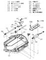
ところでナット19は第1のシャフト13に略平行に設けられ、円柱状の表面に螺旋溝が形成された、移動手段を構成するリードスクリュー20と係合している。図2、図4で示されているようにリードスクリュー20の一端には移動手段を構成するスクリューギヤ22が固着されており、スクリューギヤ22は移動手段を構成するモータ部材23のモータシャフト24に圧入された移動手段の1つであるモータギヤ25と噛合し、モータ部材23からの回転力をモータギヤ23と噛合する中継ギヤ26を介してスクリューギヤ22に減速伝達し、リードスクリュー20に伝達している。これらのモータ部材23、中継ギヤ26、スクリューギヤ22はシャーシ部材10に形成されている各溝部に配設され、上下位置はモータカバー27で規制され、モータカバー27はネジ28a、28bによってシャーシ部材10に固定されている。
【0031】
以上のように構成された光ディスク装置について、以下その基本動作について説明する。まず、スピンドルモータ12を回転させて、ターンテーブル11に載置されたディスク0を回転させる。続いて、モータ部材23によりモータギヤ25、中継ギヤ26、スクリューギヤ22を介してリードスクリュー21を回転させる。これにより、リードスクリュー21と係合するナット19はリードスクリュー21の軸方向に送られる。これに伴いナット19が固定され、かつ第1のシャフト13部材、第2のシャフト部材14によりディスク半径方向に摺動自在にガイドされた光ピックアップ手段16はディスク半径方向に送られる。これにより、光ピックアップ手段16をディスク0の任意のトラック近傍に移動して、ディスク0の任意のトラック上の情報を読み出す、または書き込むことができる。
【0032】
近年、ディスクの記録密度の高密度化が進み、それを読み書きする情報記憶装置の精度も高い物が要求されてきている。光ディスクの場合、特にディスク記録面とピックアップの光軸の傾き精度は高くする必要があり、量産性のある加工の精度ではこの要求を満たさないため、組立時に調整する必要がある。
【0033】
次に、この調整構造について図4〜図9を用いて説明する。第2のシャフト部材14の両端部には各々Dカット部30a、30bが形成されており、ディスクの内周側の一端にはDカット部30a、30bを圧入固着させるための半円穴溝部31が形成されたカム部材の一つであるカム部材A32が第2のシャフト部材14の一端に固着されている。第2のシャフト部材14の他端には同様に半円穴溝部33が形成されたカム部材の一つであるカム部材B34が固着されている。カム部材A32には第2のシャフト部材14のディスク外周部に配設される第2の付勢部材としての調整板バネA35に形成されている穴部36と嵌合する円筒状凸部37が形成されており、またカム部材B34にはシャーシ部材10に形成されている穴部38と嵌合する円筒状凸部39が形成されている。
【0034】
特に、カム部材A32およびカム部材B34の円筒状凸部37、39のセンターと第2のシャフト部材14の両端で嵌合する半円状溝部37,39のセンターとは偏芯して構成されており、カム部材を回転させることにより、第2のシャフト部材14の高さを変化させることができ、これによりディスクと光ピックアップの光軸とのT方向の調整が可能となる。また、図4、図5および図6で示されているように、カム部材B34の円筒状凸部39以外のシャーシ部材10の穴38と接する端面には放射状凸部40が略等角度間隔で放射状に形成されており、この放射状凸部40の間の溝と係合するごとく、シャーシ部材の穴部近傍に凸部41が形成されている。また、カム部材B34には外形部に矩形状凸部42が形成されており、この矩形状凸部42を用いてシャフトを回転させることもできる。さらに、円筒状凸部39の端面にはレンチ等を使用して回転させることができるように角穴43が設けられている。また、カム部材B34には調整板バネA35によりシャフトのスラスト方向に付勢されている。これにより、調整するために第2のシャフト部材14と放射状凸部40の1ピッチごとに係止してクリック感がもたらされる。もちろん性能に影響の及ばない調整精度に多分割されているのはいうまでもない。この回転係止により、冶具等で調整後に冶具を離す際にひっかかり等で回転がずれてしまうことがなくなり、安定した調整を行うことが可能となる。
【0035】
ところで、図7に示すように、カム部材A32の円筒状凸部37は調整板バネA35に形成されている穴部36と嵌合しており、調整板バネA25は調整ネジ44を配設した「コ」の字形状の板金からなる第2の保持部材45で挟持するごとく配設されており、調整板バネA35に形成されている付勢部46が第2の保持部材45の「コ」の字状の一端面47と当接しており、さらに調整ネジ44は第2の保持部材45に形成されているネジ当接部48で当接し、第2の保持部材45の「コ」の字形状の内部で付勢力がかかっているため、合成樹脂製のシャーシ部材には直接バネ力がかからなく、合成樹脂のクリープ等によるシャーシ部材10の変形が発生しない。また、シャーシ部材10に形成されている壁部49と調整板バネA35に形成されている曲げ部50との当接付勢により第2のシャフト部材14をスラスト方向に付勢している。この第2の保持部材45はシャーシ部材10に形成されているボス部51でネジ52により固定されている。
【0036】
次に図8および図9に示されているように、光ピックアップ手段16の軸受部と嵌合する第1のシャフト部材13の一端に形成されている円筒状凸部55は、第1の付勢部材である調整板バネB56に形成されている穴部57と嵌合しており、第1のシャフト部材13の他端はシャーシ部材10に形成されている穴部58と嵌合している。また、シャーシ部材10には調整板バネB56を挟持するごとく、「コ」の字形状の第1の保持部材59が配設され、シャーシ部材10に形成されているボス部60でネジ61で固定されている。また、第1の保持部材59には調整ネジ62が配設されており、調整ネジ62の端部63は調整板バネB56の当接面64で当接しており、さらに第1の保持部材58のコの字形状の端面とは調整板バネB56に形成されている当接部65および66で当接しており、当接部65と当接部66と調整ネジの当接部64との間で付勢力を発生させている。調整板バネB56のシャフト軸方向の規制はシャーシ部材10に形成されている規制部67で位置規制されている。さらにこの調整板バネB56はリードスクリュー21の軸方向の付勢も同時に調整板バネB56のスクリュー付勢面68で行われる。また、前述の第2の保持部材45と同様、第1の保持部材59も「コ」の字形状の内部で付勢力がかかるため、合成樹脂製のシャーシ部材には直接バネ力がかからなく、合成樹脂のクリープ等によるシャーシ部材10の変形が発生しない。
【0037】
【発明の効果】
以上のように本発明は、円盤状記録媒体を回転駆動させるための回転駆動手段と、円盤状記録媒体の信号を再生もしくは記録再生するための光ピックアップ手段と、
光ピックアップ手段を円盤状記録媒体の径方向に移動させる移動手段と、
光ピックアップ手段の移動をガイドするためのガイド手段と、
回転駆動手段と光ピックアップ手段と移動手段とガイド手段とを配設するシャーシ部材とを備え、
ガイド手段は、光ピックアップ手段の軸受部と嵌合する第1のシャフト部材と、第1のシャフト部材と略平行に配設された第2のシャフト部材を有し、
第2のシャフト部材の両端には第2のシャフト部材と嵌合する偏芯穴部が形成された円筒形状のカム部材が固着されており、カム部材を回転させることにより、第1のシャフト部材に対する第2のシャフト部材の高さを変化させ、円盤状記録媒体のタンジェンシャル方向に対して、円盤状記録媒体の記録面に対する光ピックアップ手段の光軸を調整可能とし、
第1および第2のシャフト部材は、円盤状記録媒体の外周側の一端を挟持するコの字形状の第1および第2の保持部材により保持され、
第1および第2の保持部材は、第1および第2のシャフト部材の保持部材側における高さ調整を行う調整ネジを有し、調整ネジにより、シャフト部材を傾斜させることによって円盤状記録媒体のラジアル方向に対して、円盤状記録媒体の記録面に対する光ピックアップ手段の光軸を調整する構成となっている。
【0038】
この構成によって、光ピックアップとディスクの相対的な傾きを容易に調整できるようになり、調整時間を短縮化できるとともに、調整設備においても簡易化が実現できる。
【0039】
また、第2のシャフト部材の両端に固着されたカム部材のうち、一方のカム部材の端面にはシャーシ部材に形成された穴部と嵌合するごとく凸部が形成されており、凸部以外のシャーシ部材と圧接する面には等角度間隔で複数個の放射状凸部が形成されており、放射状凸部と係合するごとく少なくとも1ヶ以上の凸部がシャーシ部材の対向する面に形成することにより、冶具等で調整後に冶具を離す際にひっかかり等で回転がずれてしまうことがなくなり、安定した調整を行うことが可能となる。
【0040】
また、第1および第2のシャフト部材の一端を挟持する「コ」の字形状の第1および第2の保持部材と第1および第2の保持部材と第1および第2のシャフト部材の一端を付勢するごとく保持部材に配設された第1および第2の付勢部材とで構成することにより、装置の小型軽量化さらに低価格化に対応するためにシャーシを合成樹脂化した場合にでも、調整バネの反力がシャーシにかからないため、合成樹脂クリープによる変形により調整がずれてしまうことなくシステムのマージンを確保することができるという優れた効果が得られる。
【図面の簡単な説明】
【図1】 本発明の実施の形態1における光ディスク装置の上部からの平面図
【図2】 同、下部からの構成斜視図
【図3】 同、光ピックアップとリードスクリューとの係合手段を示す斜視図
【図4】 同、駆動部および第2のシャフト部の構成斜視図
【図5】 同、第2のシャフト部を示す斜視図
【図6】 同、カムAを示す斜視図
【図7】 同実施の形態1における第2のシャフト部の調整構造を示す側面図
【図8】 同実施の形態1における第1のシャフト部材と光ピックアップを示す斜視図
【図9】 同実施の形態1における第1のシャフト部の調整構造を示す斜視図
【図10】 従来の光ディスク装置の斜視構成図
【図11】 同、断面概略構成図
【符号の説明】
10 シャーシ部材
12 スピンドルモータ
13 第1のシャフト部材
14 第2のシャフト部材
15 ディスク
16 光ピックアップ手段
17 板バネ部材
19 ナット
20 アース接続部材
21 リードスクリュー
22 スクリューギヤ
23 モータ部材
25 モータギヤ
26 中継ギヤ
27 モータカバー
32 カム部材A
34 カム部材B
35 調整板バネA
40 放射状凸部
45 第2の保持部材
56 調整板バネB
59 第1の保持部材[0001]
BACKGROUND OF THE INVENTION
The present invention relates to an optical disc apparatus that records or reproduces information by irradiating an optical disc that is an optical recording medium with a light beam with high accuracy.
[0002]
[Prior art]
In recent years, optical disc apparatuses having a traverse mechanism for driving and controlling an optical head for irradiating a light beam in the radial direction of the optical disc are computer peripheral devices (CD-ROM, magneto-optical disc, phase change disc, etc.), AV equipment (CD, VideoCD, It has been attracting attention as a key part of information storage / playback apparatuses such as video disks and DVDs. In particular, as information storage / reproduction devices become lighter, thinner, and smaller, optical disc devices are required to be smaller and lighter, and reliability and assemblability have been emphasized.
[0003]
Hereinafter, a conventional optical disc apparatus will be described with reference to the drawings.
[0004]
FIG. 10 is a structural perspective view showing a conventional optical disk apparatus, showing a partial cross-sectional perspective view, and FIG. 11 is a schematic cross-sectional structural view taken along the broken line V in FIG.
[0005]
10 and 11,
[0006]
The
[0007]
That is, as shown in FIGS. 10 and 11, a
[0008]
Similarly, an inner
[0009]
The outer end of the
[0010]
A
[0011]
A
[0012]
[0013]
[0014]
The operation of the optical disk apparatus configured as described above will be described below.
[0015]
First, the
[0016]
As is well known, the disk 0 is usually made of a synthetic resin and has a slight warp when placed on the
[0017]
In order to adjust the relative inclination between the
[0018]
The
[0019]
[Problems to be solved by the invention]
However, the conventional configuration described above has the following problems.
[0020]
First, in order to correct the tilt between the optical axis of the optical pickup and the recording surface of the optical pickup in the tangential (T) direction of the disc, the adjustment screws are simultaneously adjusted with the same amount of movement at the two ends of the sub shaft. When adjusting for repair, etc., it is difficult to adjust and takes a long time to adjust, and even when adjusting with a production jig, etc., the production jig apparatus can be large and complicated, so the production jig apparatus becomes expensive. Had the problem of becoming.
[0021]
Next, when the chassis is made of synthetic resin in order to reduce the size and weight of the device and to reduce the price in accordance with the support for portable devices, the reaction force of the adjustment spring is always applied to the chassis, so deformation due to synthetic resin creep As a result, the adjustment is deviated, which makes it difficult to secure a system margin.
[0022]
The present invention solves the above-mentioned conventional problems, and provides an optical disc apparatus that can be easily adjusted, shorten the adjustment time, can be simplified in adjustment equipment, and can be reduced in size, weight, and cost. With the goal.
[0023]
[Means for Solving the Problems]
In order to achieve this object, the optical disc apparatus of the present invention
Rotation driving means for rotationally driving the disk-shaped recording medium, optical pickup means for reproducing or recording / reproducing signals of the disk-shaped recording medium, and moving the optical pickup means in the radial direction of the disk-shaped recording medium Moving means, guide means for guiding the movement of the optical pickup means, and a chassis member in which the rotation driving means, the optical pickup means, the moving means, and the guide means are disposed. A first shaft member fitted to a bearing portion of the optical pickup means; a second shaft member disposed substantially parallel to the first shaft member; and at both ends of the second shaft member Is fixed with a cylindrical cam member formed with an eccentric hole for fitting with the second shaft member, and the first cam member is rotated by rotating the cam member. By changing the height of the second shaft member relative to the shaft member, the optical axis of the optical pickup means relative to the recording surface of the disc-shaped recording medium can be adjusted with respect to the tangential direction of the disc-shaped recording medium, The first and second shaft members are held by U-shaped first and second holding members that sandwich one end of the outer periphery of the disk-shaped recording medium, and the first and second holding members are And an adjusting screw for adjusting the height of the first and second shaft members on the holding member side, and the shaft member is inclined by the adjusting screw with respect to the radial direction of the disc-shaped recording medium. Adjusting the optical axis of the optical pickup means relative to the recording surface of the disc-shaped recording mediumOf the cam members fixed to both ends of the second shaft member, a convex portion is formed on the end surface of one of the cam members so as to fit with the hole formed in the chassis member. A plurality of radial projections are formed at equiangular intervals on the surface that is in pressure contact with the chassis member other than the portion, and at least one projection is opposed to the chassis member so as to engage with the radial projection. Formed on the surfaceIt is the composition to do.
[0024]
With this configuration, the relative inclination between the optical pickup and the disk can be easily adjusted, the adjustment time can be shortened, and simplification can be realized in the adjustment equipment.
[0025]
DETAILED DESCRIPTION OF THE INVENTION
Hereinafter, an optical disk device according to an embodiment of the present invention will be described with reference to the drawings.
[0026]
(Embodiment 1)
FIG. 1 is a plan view from the upper part (that is, the disk mounting surface side) of the optical disk apparatus according to the first embodiment of the present invention, FIG. 2 is a perspective view of the structure from the lower part, and FIG. 3 is an engagement between an optical pickup and a lead screw. 4 is a perspective view showing the structure of the drive portion and the second shaft portion, FIG. 5 is a perspective view showing the second shaft portion, FIG. 6 is a perspective view showing the cam A, and FIG. FIG. 8 is a perspective view showing a first shaft member and an optical pickup, and FIG. 9 is a perspective view showing an adjustment structure of the first shaft portion.
[0027]
In FIGS. 1, 2 and 3,
[0028]
The
[0029]
As shown in FIG. 3, a
[0030]
By the way, the
[0031]
The basic operation of the optical disk apparatus configured as described above will be described below. First, the
[0032]
In recent years, the recording density of disks has been increased, and information storage devices that read and write data have been required to have high accuracy. In the case of an optical disc, it is particularly necessary to increase the tilt accuracy of the disc recording surface and the optical axis of the pickup, and the accuracy of mass-productive processing does not satisfy this requirement.
[0033]
Next, this adjustment structure will be described with reference to FIGS. D-
[0034]
In particular, at the center of the cylindrical
[0035]
By the way, as shown in FIG. 7, the cylindrical
[0036]
Next, as shown in FIGS. 8 and 9, the bearing portion of the optical pickup means 16 andFittingThe cylindrical
[0037]
【The invention's effect】
As described above, the present invention provides a rotational drive means for rotationally driving a disk-shaped recording medium, an optical pickup means for reproducing or recording / reproducing a signal of the disk-shaped recording medium,
Moving means for moving the optical pickup means in the radial direction of the disk-shaped recording medium;,
Guide means for guiding the movement of the optical pickup means;
A chassis member for disposing the rotation driving means, the optical pickup means, the moving means, and the guide means;
Guide handThe stage isA bearing portion of the optical pickup means;FittingA first shaft member to be combined, and a second shaft member disposed substantially parallel to the first shaft member,
At both ends of the second shaft memberSecondShaft member andFittingA cylindrical cam member formed with an eccentric hole to be joined is fixed, and by rotating the cam memberChanging the height of the second shaft member relative to the first shaft member;Disc-shaped recording mediaTangentialThe optical axis of the optical pickup means relative to the recording surface of the disc-shaped recording medium can be adjusted with respect to the direction.age,
The first and second shaft members are held by U-shaped first and second holding members that sandwich one end on the outer peripheral side of the disc-shaped recording medium,
The first and second holding members have an adjusting screw for adjusting the height of the first and second shaft members on the holding member side, and the shaft member is tilted by the adjusting screw so that the disc-shaped recording medium is Adjust the optical axis of the optical pickup means relative to the recording surface of the disc-shaped recording medium with respect to the radial direction.It has a configuration.
[0038]
With this configuration, the relative inclination between the optical pickup and the disk can be easily adjusted, the adjustment time can be shortened, and simplification can be realized in the adjustment equipment.
[0039]
Further, among the cam members fixed to both ends of the second shaft member, a hole formed in the chassis member is formed on the end surface of one cam member.MatingA convex portion is formed, and a plurality of radial convex portions are formed at equiangular intervals on the surface that is in pressure contact with the chassis member other than the convex portion. At least one radial convex portion is engaged with the radial convex portion. By forming the convex portions on the opposing surfaces of the chassis member, the rotation does not shift due to catching or the like when the jig is released after adjustment with the jig or the like, and stable adjustment can be performed.
[0040]
The first and second holding members, the first and second holding members, and the one ends of the first and second shaft members having a “U” shape sandwiching one ends of the first and second shaft members. When the chassis is made of synthetic resin in order to reduce the size and weight of the device and to reduce the price by configuring the first and second urging members disposed on the holding member as if urging However, since the reaction force of the adjusting spring is not applied to the chassis, an excellent effect can be obtained that the margin of the system can be secured without the adjustment being shifted due to the deformation caused by the synthetic resin creep.
[Brief description of the drawings]
FIG. 1 is a plan view from the top of an optical disk device according to a first embodiment of the present invention.
FIG. 2 is a perspective view of the configuration from the bottom.
FIG. 3 is a perspective view showing an engagement means between the optical pickup and the lead screw.
[Fig. 4] The drive unit andAndConfiguration perspective view of second shaft portion
FIG. 5 is a perspective view showing the second shaft portion.
FIG. 6 is a perspective view showing the cam A.
7 is a side view showing an adjustment structure of a second shaft portion in the first embodiment. FIG.
FIG. 8 is a perspective view showing a first shaft member and an optical pickup in the first embodiment.
FIG. 9 is a perspective view showing an adjustment structure of a first shaft portion in the first embodiment.
FIG. 10 is a perspective configuration diagram of a conventional optical disc apparatus.
FIG. 11 is a schematic sectional view of the same.
[Explanation of symbols]
10 Chassis members
12 Spindle motor
13 First shaft member
14 Second shaft member
15 discs
16 Optical pickup means
17 Leaf spring member
19 Nut
20 Earth connection member
21 Lead screw
22 Screw gear
23 Motor member
25 Motor gear
26 Relay gear
27 Motor cover
32 Cam member A
34 Cam member B
35 Adjusting leaf spring A
40 Radial convex part
45 Second holding member
56 Adjusting leaf spring B
59 First holding member
Claims (2)
前記ガイド手段は、前記光ピックアップ手段の軸受部と嵌合する第1のシャフト部材と、該第1のシャフト部材と略平行に配設された第2のシャフト部材を有し、
前記第2のシャフト部材の両端には当該第2のシャフト部材と嵌合する偏芯穴部が形成された円筒形状のカム部材が固着されており、前記カム部材を回転させることにより、前記第1のシャフト部材に対する当該第2のシャフト部材の高さを変化させ、前記円盤状記録媒体のタンジェンシャル方向に対して、前記円盤状記録媒体の記録面に対する光ピックアップ手段の光軸を調整可能とし、
前記第1および第2のシャフト部材は、前記円盤状記録媒体の外周側の一端を挟持するコの字形状の第1および第2の保持部材により保持され、
前記第1および第2の保持部材は、前記第1および第2のシャフト部材の当該保持部材側における高さ調整を行う調整ネジを有し、当該調整ネジにより、シャフト部材を傾斜させることによって前記円盤状記録媒体のラジアル方向に対して、前記円盤状記録媒体の記録面に対する光ピックアップ手段の光軸を調整し、
第2のシャフト部材の両端に固着されたカム部材のうち、一方のカム部材の端面には前記シャーシ部材に形成された穴部と嵌合するごとく凸部が形成されており、前記凸部以外の前記シャーシ部材と圧接する面には等角度間隔で複数個の放射状凸部が形成されており、前記放射状凸部と係合するごとく少なくとも1ヶ以上の凸部が前記シャーシ部材の対向する面に形成する構成としたことを特徴とする光ディスク装置。Rotation driving means for rotationally driving the disk-shaped recording medium, optical pickup means for reproducing or recording / reproducing signals of the disk-shaped recording medium, and moving the optical pickup means in the radial direction of the disk-shaped recording medium Moving means, guide means for guiding the movement of the optical pickup means, and a chassis member for disposing the rotation driving means, the optical pickup means, the moving means, and the guide means,
The guide means includes a first shaft member that fits with a bearing portion of the optical pickup means, and a second shaft member that is disposed substantially parallel to the first shaft member,
Cylindrical cam members each having an eccentric hole that is fitted to the second shaft member are fixed to both ends of the second shaft member. By rotating the cam member, By changing the height of the second shaft member relative to the one shaft member, the optical axis of the optical pickup means relative to the recording surface of the disc-shaped recording medium can be adjusted with respect to the tangential direction of the disc-shaped recording medium. ,
The first and second shaft members are held by U-shaped first and second holding members that sandwich one end on the outer peripheral side of the disc-shaped recording medium,
The first and second holding members have adjustment screws for adjusting the height of the first and second shaft members on the holding member side, and the shaft members are inclined by the adjustment screws. Adjusting the optical axis of the optical pickup means relative to the recording surface of the disc-shaped recording medium with respect to the radial direction of the disc-shaped recording medium ;
Of the cam members fixed to both ends of the second shaft member, a convex portion is formed on the end surface of one cam member so as to be fitted with a hole formed in the chassis member. A plurality of radial protrusions are formed at equiangular intervals on the surface in pressure contact with the chassis member, and at least one protrusion is opposed to the chassis member so as to engage with the radial protrusion. An optical disc apparatus characterized in that the optical disc apparatus is formed in the following manner .
前記ガイド手段は、前記光ピックアップ手段の軸受部と嵌合する第1のシャフト部材と、該第1のシャフト部材と略平行に配設された第2のシャフト部材を有し、
前記第2のシャフト部材の両端には当該第2のシャフト部材と嵌合する偏芯穴部が形成された円筒形状のカム部材が固着されており、前記カム部材を回転させることにより、前記第1のシャフト部材に対する当該第2のシャフト部材の高さを変化させ、前記円盤状記録媒体のタンジェンシャル方向に対して、前記円盤状記録媒体の記録面に対する光ピックアップ手段の光軸を調整可能とし、
前記第1および第2のシャフト部材は、前記円盤状記録媒体の外周側の一端を挟持するコの字形状の第1および第2の保持部材により保持され、
前記第1および第2の保持部材は、前記第1および第2のシャフト部材の当該保持部材側における高さ調整を行う調整ネジを有し、当該調整ネジにより、シャフト部材を傾斜させることによって前記円盤状記録媒体のラジアル方向に対して、前記円盤状記録媒体の記録面に対する光ピックアップ手段の光軸を調整し、
前記第1の付勢部材は前記第1のシャフト部材の付勢とともに、前記リードスクリューの一つの端面をスラスト方向に付勢するごとく構成されていることを特徴とする光ディスク装置。 Rotation driving means for rotationally driving the disk-shaped recording medium, optical pickup means for reproducing or recording / reproducing signals of the disk-shaped recording medium, and moving the optical pickup means in the radial direction of the disk-shaped recording medium Moving means, guide means for guiding the movement of the optical pickup means, a chassis member in which the rotation driving means, the optical pickup means, the moving means, and the guide means are disposed, and the moving means includes the first member A lead screw having a spiral groove formed on a cylindrical surface substantially parallel to the shaft member, a driving means for rotationally driving the lead screw, and an optical pickup means, and being engaged with the spiral groove and having a driving force Engaging means for transmitting from the lead screw to the optical pickup means,
The guide means includes a first shaft member that fits with a bearing portion of the optical pickup means, and a second shaft member that is disposed substantially parallel to the first shaft member,
Cylindrical cam members each having an eccentric hole that is fitted to the second shaft member are fixed to both ends of the second shaft member. By rotating the cam member, By changing the height of the second shaft member relative to the one shaft member, the optical axis of the optical pickup means relative to the recording surface of the disc-shaped recording medium can be adjusted with respect to the tangential direction of the disc-shaped recording medium. ,
The first and second shaft members are held by U-shaped first and second holding members that sandwich one end on the outer peripheral side of the disc-shaped recording medium,
The first and second holding members have adjustment screws for adjusting the height of the first and second shaft members on the holding member side, and the shaft members are inclined by the adjustment screws. Adjusting the optical axis of the optical pickup means relative to the recording surface of the disc-shaped recording medium with respect to the radial direction of the disc-shaped recording medium;
The optical disk apparatus according to claim 1, wherein the first urging member is configured to urge one end face of the lead screw in a thrust direction together with the urging of the first shaft member .
Priority Applications (1)
| Application Number | Priority Date | Filing Date | Title |
|---|---|---|---|
| JP2000036142A JP4221868B2 (en) | 2000-02-15 | 2000-02-15 | Optical disk device |
Applications Claiming Priority (1)
| Application Number | Priority Date | Filing Date | Title |
|---|---|---|---|
| JP2000036142A JP4221868B2 (en) | 2000-02-15 | 2000-02-15 | Optical disk device |
Publications (3)
| Publication Number | Publication Date |
|---|---|
| JP2001229548A JP2001229548A (en) | 2001-08-24 |
| JP2001229548A5 JP2001229548A5 (en) | 2007-04-05 |
| JP4221868B2 true JP4221868B2 (en) | 2009-02-12 |
Family
ID=18560226
Family Applications (1)
| Application Number | Title | Priority Date | Filing Date |
|---|---|---|---|
| JP2000036142A Expired - Fee Related JP4221868B2 (en) | 2000-02-15 | 2000-02-15 | Optical disk device |
Country Status (1)
| Country | Link |
|---|---|
| JP (1) | JP4221868B2 (en) |
Families Citing this family (5)
| Publication number | Priority date | Publication date | Assignee | Title |
|---|---|---|---|---|
| KR100457530B1 (en) * | 2002-07-24 | 2004-11-17 | 삼성전자주식회사 | Tilt adjusting apparatus for optical disc player |
| KR100457531B1 (en) * | 2002-07-24 | 2004-11-17 | 삼성전자주식회사 | Tilt adjusting apparatus and pick up deck having the same for optical disc player |
| JP4622994B2 (en) | 2006-11-20 | 2011-02-02 | 船井電機株式会社 | Optical pickup guide device |
| JP4723549B2 (en) * | 2007-10-12 | 2011-07-13 | クラリオン株式会社 | Disc player |
| JP2011103152A (en) * | 2009-11-10 | 2011-05-26 | Sharp Corp | Optical disk drive |
-
2000
- 2000-02-15 JP JP2000036142A patent/JP4221868B2/en not_active Expired - Fee Related
Also Published As
| Publication number | Publication date |
|---|---|
| JP2001229548A (en) | 2001-08-24 |
Similar Documents
| Publication | Publication Date | Title |
|---|---|---|
| KR100243191B1 (en) | Optical disk player | |
| US6388980B2 (en) | Disc drive | |
| JP3009639B2 (en) | Disc player with tilt adjustment | |
| JP2002157749A (en) | Optical disk unit, adjustment method for the optical disk device. and entertainment device | |
| US6385160B1 (en) | Pickup adjusting apparatus of a disk player | |
| JP2962696B2 (en) | Disk player with phase difference and tilt adjustment | |
| JP2846862B2 (en) | Optical recording / reproducing apparatus provided with means for adjusting installation angle of spindle motor | |
| US6373812B2 (en) | Disk player capable of adjusting tilt of optical pickup | |
| US7213251B2 (en) | Guide shaft tilt adjusting apparatus for optical disc player | |
| JP4221868B2 (en) | Optical disk device | |
| JP2793176B2 (en) | Disc player pickup tilt adjustment device | |
| KR20050014675A (en) | Disk drive apparatus | |
| JP3480294B2 (en) | Information storage device | |
| JP3478111B2 (en) | Recording and playback device | |
| JP2000132842A (en) | Optical disk device and its tilt adjusting method | |
| JPH09223353A (en) | Optical disk device | |
| JP3876860B2 (en) | Recording / playback device | |
| JPH11224482A (en) | Recording and reproducing device | |
| JP2002015434A (en) | Disk device | |
| US7124421B2 (en) | Lead screw adjustment structure of disc drive | |
| KR100188941B1 (en) | Pickup guide apparatus of disc driver | |
| JP3885634B2 (en) | Recording / playback device | |
| JP2926868B2 (en) | Rotating head device | |
| KR200351543Y1 (en) | Skew Control Device in Optical Driving Apparatus | |
| KR20010024092A (en) | Disk Reproduction Apparatus |
Legal Events
| Date | Code | Title | Description |
|---|---|---|---|
| A521 | Written amendment |
Free format text: JAPANESE INTERMEDIATE CODE: A523 Effective date: 20070215 |
|
| A621 | Written request for application examination |
Free format text: JAPANESE INTERMEDIATE CODE: A621 Effective date: 20070215 |
|
| RD01 | Notification of change of attorney |
Free format text: JAPANESE INTERMEDIATE CODE: A7421 Effective date: 20070313 |
|
| A977 | Report on retrieval |
Free format text: JAPANESE INTERMEDIATE CODE: A971007 Effective date: 20080205 |
|
| A131 | Notification of reasons for refusal |
Free format text: JAPANESE INTERMEDIATE CODE: A131 Effective date: 20080304 |
|
| A521 | Written amendment |
Free format text: JAPANESE INTERMEDIATE CODE: A523 Effective date: 20080428 |
|
| TRDD | Decision of grant or rejection written | ||
| A01 | Written decision to grant a patent or to grant a registration (utility model) |
Free format text: JAPANESE INTERMEDIATE CODE: A01 Effective date: 20081028 |
|
| A01 | Written decision to grant a patent or to grant a registration (utility model) |
Free format text: JAPANESE INTERMEDIATE CODE: A01 |
|
| A61 | First payment of annual fees (during grant procedure) |
Free format text: JAPANESE INTERMEDIATE CODE: A61 Effective date: 20081110 |
|
| FPAY | Renewal fee payment (event date is renewal date of database) |
Free format text: PAYMENT UNTIL: 20111128 Year of fee payment: 3 |
|
| FPAY | Renewal fee payment (event date is renewal date of database) |
Free format text: PAYMENT UNTIL: 20121128 Year of fee payment: 4 |
|
| FPAY | Renewal fee payment (event date is renewal date of database) |
Free format text: PAYMENT UNTIL: 20131128 Year of fee payment: 5 |
|
| LAPS | Cancellation because of no payment of annual fees |