JP4220071B2 - Color correction relation extraction method and color correction method - Google Patents
Color correction relation extraction method and color correction method Download PDFInfo
- Publication number
- JP4220071B2 JP4220071B2 JP22078399A JP22078399A JP4220071B2 JP 4220071 B2 JP4220071 B2 JP 4220071B2 JP 22078399 A JP22078399 A JP 22078399A JP 22078399 A JP22078399 A JP 22078399A JP 4220071 B2 JP4220071 B2 JP 4220071B2
- Authority
- JP
- Japan
- Prior art keywords
- color
- image
- color correction
- colorimetric
- coordinate value
- Prior art date
- Legal status (The legal status is an assumption and is not a legal conclusion. Google has not performed a legal analysis and makes no representation as to the accuracy of the status listed.)
- Expired - Fee Related
Links
- 238000012937 correction Methods 0.000 title claims description 149
- 238000000034 method Methods 0.000 title claims description 112
- 238000000605 extraction Methods 0.000 title claims description 30
- 238000006243 chemical reaction Methods 0.000 claims description 118
- 238000005259 measurement Methods 0.000 claims description 12
- 239000003086 colorant Substances 0.000 claims description 7
- 238000010586 diagram Methods 0.000 description 18
- 238000013507 mapping Methods 0.000 description 15
- 238000011161 development Methods 0.000 description 8
- 238000004040 coloring Methods 0.000 description 4
- 239000000049 pigment Substances 0.000 description 4
- 239000000463 material Substances 0.000 description 3
- 230000002441 reversible effect Effects 0.000 description 2
- 238000001035 drying Methods 0.000 description 1
- 230000000694 effects Effects 0.000 description 1
- 238000005516 engineering process Methods 0.000 description 1
- 230000001678 irradiating effect Effects 0.000 description 1
- 239000011159 matrix material Substances 0.000 description 1
- 238000005457 optimization Methods 0.000 description 1
- 230000009466 transformation Effects 0.000 description 1
Images


Classifications
-
- H—ELECTRICITY
- H04—ELECTRIC COMMUNICATION TECHNIQUE
- H04N—PICTORIAL COMMUNICATION, e.g. TELEVISION
- H04N1/00—Scanning, transmission or reproduction of documents or the like, e.g. facsimile transmission; Details thereof
- H04N1/46—Colour picture communication systems
- H04N1/56—Processing of colour picture signals
- H04N1/60—Colour correction or control
- H04N1/6016—Conversion to subtractive colour signals
- H04N1/6019—Conversion to subtractive colour signals using look-up tables
-
- G—PHYSICS
- G03—PHOTOGRAPHY; CINEMATOGRAPHY; ANALOGOUS TECHNIQUES USING WAVES OTHER THAN OPTICAL WAVES; ELECTROGRAPHY; HOLOGRAPHY
- G03B—APPARATUS OR ARRANGEMENTS FOR TAKING PHOTOGRAPHS OR FOR PROJECTING OR VIEWING THEM; APPARATUS OR ARRANGEMENTS EMPLOYING ANALOGOUS TECHNIQUES USING WAVES OTHER THAN OPTICAL WAVES; ACCESSORIES THEREFOR
- G03B27/00—Photographic printing apparatus
- G03B27/72—Controlling or varying light intensity, spectral composition, or exposure time in photographic printing apparatus
- G03B27/80—Controlling or varying light intensity, spectral composition, or exposure time in photographic printing apparatus in dependence upon automatic analysis of the original
-
- H—ELECTRICITY
- H04—ELECTRIC COMMUNICATION TECHNIQUE
- H04N—PICTORIAL COMMUNICATION, e.g. TELEVISION
- H04N1/00—Scanning, transmission or reproduction of documents or the like, e.g. facsimile transmission; Details thereof
- H04N1/46—Colour picture communication systems
- H04N1/56—Processing of colour picture signals
- H04N1/60—Colour correction or control
- H04N1/603—Colour correction or control controlled by characteristics of the picture signal generator or the picture reproducer
- H04N1/6033—Colour correction or control controlled by characteristics of the picture signal generator or the picture reproducer using test pattern analysis
Description
【0001】
【発明の属する技術分野】
本発明は、原画像が色修正を伴って写される場合の色修正前後の色相互の対応関係を抽出する色修正関係抽出方法、およびその色修正を再現する色修正方法に関する。
【0002】
【従来の技術】
印刷や写真などの分野では、リバーサルフィルム上の原画像を印刷用紙や印画紙に写して印刷物や写真を作成する際に、オペレータが色修正を施すことにより人間の見た目に好ましい色合いを持つ高品質な画像を印刷物上や写真上に作成することがしばしば行われている。
【0003】
このような高品質な画像は、従来は、印刷物や写真を作成するシステムが特定され、そのシステムのオペレータの経験に基づいてシステムが最適化されることによって作成されている。
【0004】
例えば、印刷の場合には、リバーサルフィルム上の原画像がスキャナで読みとられて画像データが取得される際に、オペレータがスキャナを操作することによって画像データが修正されている。この修正された画像データに従って画像が印刷されることによって好ましい色合いを持つ画像が作成される。このとき、スキャナによって取得される画像データを修正するための修正パラメータは、スキャナオペレータの経験によるノウハウに基づいて、印刷用紙や印刷インキ等も含むシステム全体の性質が考慮されつつ最適化されている。つまり、リバーサルフィルム上の原画像から好ましい色合いを持つ画像を作る絵作りのノウハウはスキャナオペレータが持っていることとなる。ここで、スキャナオペレータが、あるフィルムとある印刷インク等との組み合わせに対して修正パラメータを最適化することにより好ましい色合いを持つ画像を得たとしても、フィルムや印刷インク等が別のフィルムや別の印刷インク等に換わるとその修正パラメータは不適切となり、再び修正パラメータを最適化する必要がある。
【0005】
また、写真の場合には、ラボシステムにリバーサルフィルムが装填され、装填されたリバーサルフィルムに露光用の調整された光が照射されることにより色合いが修正された画像が得られ、得られた画像が印画紙に焼き付けられることによって好ましい色合いを持つ画像が作成される。このとき、露光用の光のR光G光B光のバランスや露光時間等は、ラボシステムのオペレータやラボシステムの自動調整機構によって、フィルムや光源や印画紙等を含むシステム全体の性質が考慮されつつ最適化されている。また、フィルムの種類と印画紙の種類との組み合わせも、好ましい色合いの画像が得られるような最適な組み合わせが選択されている。つまり、好ましい色合いの画像を作る絵作りのノウハウはラボシステムのオペレータやラボシステムのメーカやフィルムメーカなどが持っていることとなる。ここでも、あるフィルムとある印画紙との組み合わせについて露光時間等を最適化したとしても、例えば、新たに開発されたフィルム等を用いると、フィルムと印画紙との組み合わせや露光時間等は不適切となり、再び露光時間等を最適化する必要がある。
【0006】
【発明が解決しようとする課題】
このように、印刷の場合および写真の場合双方において、新製品の開発などによりフィルム等が換わると好ましい色合いを持つ画像を作るために最適化をやり直さなければならない。
【0007】
さらに、近年におけるデジタル技術の進歩に伴って、異なる業界やメディアの間で画像のやり取りを行うことが増加しつつある。例えば、印刷物を配布することに代えて印刷物の画像をインターネットのホームページ等に載せる場合には、印刷物の画像が、それまで印刷業界にはあまり関係がなかったテレビ画像に変換されることとなる。また、例えば、家庭のビデオで撮影した画像のワンショットをパーソナルコンピュータのプリンタで出力することや写真用の印画紙に出力することも行われ始めている。このような画像のやり取りが行われた場合に、画像が渡された先で、上述したような好ましい色合いを持つ高品質な画像が得られることが望ましいが、従来の技術では、上述したようなノウハウは、印刷業界や写真業界といった各業界内だけで活用することができ、別の業界でノウハウを活かすことができない。
【0008】
本発明は、上記事情に鑑み、上述したようなノウハウを抽出することができる色修正関係抽出方法、およびそのノウハウを再現することができる色修正方法を提供することを目的とする。
【0009】
【課題を解決するための手段】
上記目的を達成する本発明の色修正関係抽出方法は、原画像が色修正を伴って写されてなる複写画像の色に相当する、色の測色値を記述する測色色空間の座標値を、該複写画像の測定を経て取得する測定過程と、
原画像の色に相当する測色色空間の座標値を取得する取得過程とを踏むことにより、上記色修正前後の色相互の対応関係を抽出することを特徴とする。
【0010】
ここで、取得過程では、原画像を測色することにより測色値を取得してもよく、あるいは、発色特性が予め分かっているリバーサルフィルムなどに、レーザビームなどによって、所定の測色値の色になるように原画像を書き込んでもよい。
【0011】
本発明の色修正関係抽出方法では、原画像と複写画像のそれぞれの色に相当する測色色空間の座標値が取得されるので、原画像を写すデバイスに依存しない形で色修正のノウハウが抽出される。
【0012】
ここで、上記本発明の色修正関係抽出方法は、
上記測定過程が、複写画像を測定することにより、複写画像の色に相当する、測色色空間の座標値に変換可能な特性値を取得する特性値測定過程と、その特性値測定過程によって取得された特性値を測色色空間の座標値に変換する第1の変換過程とを含むものであってもよく、あるいは、
上記取得過程が、原画像の色に相当する、測色色空間の座標値に変換可能な特性値を取得する特性値取得過程と、その特性値取得過程によって取得された特性値を測色色空間の座標値に変換する第2の変換過程とを含むものであってもよい。
【0013】
リバーサルフィルム上や印画紙上の画像の色の測色値は、リバーサルフィルム等の色素濃度等という特性値と、そのリバーサルフィルム等の発色特性に基づいて算出することができるので、原画像や複写画像の色素濃度等を取得し、その取得された色素濃度等から測色値を算出することによっても、デバイス非依存の形でノウハウを抽出することができる。
【0014】
上記目的を達成する本発明の色修正方法は、原画像が色修正を伴って写されてなる複写画像の色に相当する、色の測色値を記述する測色色空間の座標値を、複写画像を測定することにより取得する第1部分過程と、原画像の色に相当する測色色空間の座標値を取得する第2部分過程とを踏むことにより、上記色修正前後の色それぞれに相当する測色色空間の座標値相互の対応を定義した色修正変換定義を作成する色修正変換定義作成過程と、
画像を取り込んで画像データを得、あるいは画像データに基づいた画像を出力する第1デバイスによる画像取込の特性あるいは画像出力の特性に応じた変換定義を用いて、第1デバイス用の画像データを記述する第1色空間における座標値を、デバイス非依存の測色色空間の座標値に変換する第1のデバイス変換過程と、
色修正変換定義作成過程で作成された色修正変換定義を用いて、上記色修正前の色に相当する測色色空間の座標値を、その色修正後の色に相当する測色色空間の座標値に変換する色修正変換過程と、
画像を取り込んで画像データを得、あるいは画像データに基づいた画像を出力する第2デバイスによる画像取込の特性あるいは画像出力の特性に応じた変換定義を用いて、測色色空間の座標値を、第2デバイス用の画像データを記述する第2色空間における座標値に変換する第2のデバイス変換過程とを踏んで、第1色空間で定義された画像データを、その第1色空間で定義された画像データに基づく画像に上記色修正が施されてなる画像を表す、第2色空間で定義された画像データに変換することを特徴とする。
【0015】
ここで、第1のデバイス変換過程、色修正変換過程および第2のデバイス変換過程という各変換過程は、順次に実行してもよく、あるいは、各変換過程を統合した統合変換過程を実行してもよい。
【0016】
本発明の色修正方法によれば、色修正変換定義作成過程で、原画像を写すデバイスに依存しない形で抽出されたノウハウに相当する色修正変換定義が作成され、画像データ変換過程で、その色修正変換定義が用いられて画像データが変換される。この結果、上記色修正を、原画像を写すデバイスの種類などに関わらず再現することができる。
【0017】
ここで、上記本発明の色修正方法は、
上記色修正変換定義作成過程で、上記色修正変換定義として、測色色空間の中の原画像の色として再現可能な原画像色の領域内の座標値と、測色色空間の中の複写画像の色として再現可能な複写画像色の領域内の座標値との対応を定義した色修正変換定義を作成し、
上記色修正変換過程を踏む前に、測色色空間の中の第1デバイスにより取り込まれあるいは出力される画像の色として再現可能な色の領域内の座標値を原画像色の領域内の座標値に変換する第1のガマット変換過程を踏み、
上記色修正変換過程を踏んだ後で、複写画像色の領域内の座標値を、測色色空間の中の第2デバイスにより取り込まれあるいは出力される画像の色として再現可能な色の領域内の座標値に変換する第2のガマット変換過程を踏む方法であってもよく、あるいは、
上記色修正変換定義作成過程で、上記色修正変換定義として、測色色空間の中の所定の一領域内の座標値相互の対応を定義した色修正変換定義を作成し、
上記色修正変換過程を踏む前に、測色色空間の中の第1デバイスにより取り込まれあるいは出力される画像の色として再現可能な色の領域内の座標値を上記所定領域内の座標値に変換する第1のガマット変換過程を踏み、
上記色修正変換過程を踏んだ後で、上記所定領域内の座標値を、測色色空間の中の第2デバイスにより取り込まれあるいは出力される画像の色として再現可能な色の領域内の座標値に変換する第2のガマット変換過程を踏む方法であってもよい。
【0018】
このようなガマット変換過程を踏むことにより、色修正のノウハウが、第1デバイスや第2デバイスの色再現能力を十分に活かすように再現されることとなる。
【0019】
【発明の実施の形態】
以下、本発明の実施形態について説明する。
【0020】
図1は、本発明の色修正関係抽出方法が適用されて色修正のノウハウが抽出されるシステムの一例であるラボシステムを示す図である。
【0021】
このラボシステム10のフィルムキャリア11aには、印画紙20の種類との組み合わせが最適な種類のリバーサルフィルムが装填され、そのリバーサルフィルムには光源11bからの光が調光器11cを経て照射される。調光器11cには、R光G光B光それぞれに対応する3つのフィルタが内蔵されており、各フィルタが光源11bの光に作用する程度をラボシステムのオペレータや自動調整機構が調整することによって照射光の色バランス等が調整される。照射光に照らされたリバーサルフィルムの画像は、レンズ11dによって露光ステージ11eに結像され印画紙20を露光する。また、ラボシステムのオペレータ等がシャッタ11fの開閉時間を調整することによって露光時間が調整される。
【0022】
プリント部11のペーパマガジン11gに装填されたペーパ(印画紙)20は、露光ステージ11eで露光され、オペレータの指示でリザーバ部12に送られる。リザーバ部12に送られたペーパ(印画紙)20は、一定の速度で現像部13に送られて現像部13で現像され、その後、乾燥部14で乾燥され、カッター部15で所定のサイズにカットされて写真が作成される。
【0023】
このようにして作成された写真の画像は、上述したオペレータやメーカが経験的に持つノウハウによって、フィルムと印画紙との組み合わせの選択や、フィルタの調整や露光時間の調整等が行われた結果、人間の見た目に好ましい色合いを持つ高品質な画像となっている。
【0024】
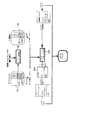
図2は、本発明の色修正関係抽出方法の第1実施形態を含む本発明の色修正方法の第1実施形態を示す図である。
【0025】
色修正関係抽出方法の第1実施形態は、図1に示すラボシステム10のオペレータやフィルムメーカ等が有する絵作りのノウハウを抽出する方法であり、色修正方法の第1実施形態は、色修正関係抽出方法の第1実施形態によってノウハウを抽出し、その抽出したノウハウを用いて色修正を行う方法である。
【0026】
色修正関係抽出方法の第1実施形態では、先ず、図1に示すラボシステム10によって、「RVフィルムA」という種類のリバーサルフィルム30に写っている人物画像や自然画像といった一般画像31が「印画紙A」という種類の印画紙40にプリントされる。このとき「RVフィルムA」と「印画紙A」との組み合わせは、画像の色合いが好ましい色合いになるような組み合わせであり、ラボシステム10のオペレータ等は、画像の色合いが好ましい色合いになるように露光量等を調整する。
【0027】
また、一般画像31が写っているリバーサルフィルム30に並べて、2次元的に配列された多数の単色パッチ32aからなるカラーチャート32が写っているリバーサルフィルム30もラボシステム10に装填され、一般画像31が印画紙40にプリントされたときの露光条件と同じ露光条件でカラーチャート32も印画紙にプリントされる。一般画像31とカラーチャート32がプリントされた印画紙40は現像され、一般画像41とカラーチャート42が写った写真40が得られる。
【0028】
次に、リバーサルフィルム30に写っているカラーチャート32を構成している各パッチ32aの色と、写真40に写っているカラーチャート42を構成している各パッチ42aの色を測色計によって測定し、各パッチ32a,42aの色の、色空間の座標値に相当する測色値を得る。測色値としては、CIEXYZ値やCIELUV値L*u*v*やCIELAB値L*a*b*などが考えられるが、ここではCIELAB値L*a*b*を得るものとする。以下では、CIELAB値L*a*b*のことを単にLabと略記する。また、CIELAB値L*a*b*のことをCIELAB色空間の座標値と称する場合がある。
【0029】
各パッチ32a,42aの色を測色して各Labを得た後、リバーサルフィルム30上の各パッチ32aのLabと写真40上の各パッチ42aのLabとを対応づけるルックアップテーブル(Look Up Table:LUT)50を作成し、作成したLUT50をコンピュータシステム100に組み込む。
【0030】
このようにして得たLUT50は、好ましい色合いの画像が得られる色修正のノウハウを示しており、本発明にいう色修正変換定義の一例である。このLUT50が得られたことにより、ノウハウは、ラボシステム10やリバーサルフィルム30や印画紙40等の種類などとは無関係な形で抽出されたこととなる。
【0031】
ここで、コンピュータシステム100にノウハウを組み込む際には、必ずしもLUTを用いて組み込む必要はなく、ノウハウに相当する変換を定義するものであれば、例えば関数式や行列であってもよい。以下では、LUTを用いてノウハウを組み込むものとして説明する。
【0032】
色修正方法の第1実施形態では、上述したようにLUT50を作成してコンピュータシステム100に組み込んだ後、例えば「RVフィルムB」という種類のリバーサルフィルムや反射プリント(例えば写真)等といった入力メディアに写っている画像がスキャナ61によって読み取られて得られた入力メディアデータや、デジタルスチールカメラ62によって撮影された画像の色を表す入力メディアデータや、CRTディスプレイ63上で作成編集された画像の色を表す入力メディアデータ等がコンピュータシステム100に入力される。ここで、入力メディアデータの形式としてはCMYデータやRGBデータなどが考えられるが、ここではRGBデータが入力されるものとする。
【0033】
次に、入力されたRGBデータに対応するデバイスの特性に基づいた入力メディア特性変換定義51によって定義される、そのRGBデータを、入力メディア上の画像の色に相当するCIELAB色空間の座標値Lab(Input)に変換する入力メディア特性変換が行われる。
【0034】
次に、上述したLUT50によって、座標値Lab(Input)を、好ましい色合いに相当する座標値Lab(Output)に変換する。
【0035】
最後に、LUT50による変換で得られた座標値Lab(Output)を、例えば「印画紙B」という種類の印画紙等という出力メディア71に画像を出力する、ディジタルプリンタ等といった出力デバイス70の出力特性に基づいた出力メディア特性変換定義52によって定義される出力メディア特性変換により、その出力デバイス70用のRGBデータに変換して出力する。ここで、出力メディア71としては、印画紙の他に、印刷物やCRTディスプレイやリバーサルフィルムなどが考えられる。また、例えば、スキャナによって取得された画像データを、インターネットのホームページの作成に利用するために、デジタルスチールカメラによって取得される画像データの形式に変換する際に本発明の色修正方法を用いてもよい。
【0036】
このようにして出力したRGBデータが出力デバイス70に入力されると、出力メディア71上に好ましい色合いの画像が作成されることとなる。そして、このような好ましい色合いの画像を得るための色修正のノウハウは、入力デバイス61,62,63や出力デバイス70の入出力特性に依らずに再現されることとなる。つまり、入力デバイスや出力デバイスに依存しない汎用の色修正システムが実現できる。
【0037】
図3は、本発明の色修正関係抽出方法の第1実施形態を含む本発明の色修正方法の第2実施形態を示す図である。
【0038】
色修正関係抽出方法の第1実施形態については重複説明を省略する。
【0039】
色修正方法の第2実施形態でも、上述したようにLUT50を作成してコンピュータシステム100に組み込んだ後、入力デバイス61,62,63用の入力メディアデータ(RGBデータ)がコンピュータシステム100に入力される。そして、このコンピュータシステム100に入力されたRGBデータを、そのRGBデータに対応する入力デバイスの特性に応じた、上述した入力メディア特性変換定義51で定義される入力メディア特性変換によって、入力メディア上の画像の色に相当するCIELAB色空間の座標値Lab(Input)に変換する。
【0040】
ところで、この座標値Lab(Input)は、CIELAB色空間上の、コンピュータシステム100に入力されたRGBデータに対応する入力デバイス61,62,63の色再現域内の座標値である。一方、コンピュータシステム100に組み込まれているLUT50は、上述した色修正関係抽出方法の第1実施形態によって作成したものであるので、リバーサルフィルム30の色再現域内の座標値と印画紙40の色再現域内の座標値とを対応づけるものである。このため、座標値Lab(Input)をそのままLUT50によって変換すると、入力デバイス61,62,63の色再現域とリバーサルフィルム30の色再現域とが相違することに起因して、色修正のノウハウが再現されないなどという不都合が生じる可能性がある。
【0041】
そこで、この色修正方法の第2実施形態では、画像の色の印象が保持された状態で、ある色再現域(ガマット)内の座標値を他の色再現域(ガマット)内の座標値に変換するガマットマッピング変換を行う。このガマットマッピング変換は、可逆な変換であるとともに、2つの色再現域の全体を相互に対応づける変換である。また、コンピュータシステム100には、ガマットマッピング変換を定義するLUT形式のガマット変換定義が組み込まれている。
【0042】
上述した入力メディア特性変換によって得られた座標値Lab(Input)には、ガマット変換定義53によって定義される、入力デバイスの色再現域内の座標値Lab(Input)をリバーサルフィルム30の色再現域内の座標値Lab(RV)に変換するガマットマッピング変換を施す。これにより、入力デバイス61,62,63の色再現域とリバーサルフィルム30の色再現域との相違に起因する不都合が回避される。
【0043】
次に、リバーサルフィルム30の色再現域内の座標値Lab(RV)を、上述したLUT50によって、好ましい色合いに相当する、印画紙(写真)40の色再現域内の座標値Lab(印画紙)に変換する。
【0044】
次に、上述したガマット変換定義53によって定義されるガマットマッピング変換を採用した理由と同様な理由で、ガマット変換定義54によって定義される、印画紙40の色再現域内の座標値Lab(印画紙)を出力デバイス70の色再現域内の座標値Lab(Output)に変換するガマットマッピング変換を行う。
【0045】
最後に、座標値Lab(Output)を、上述した出力メディア特性変換定義52によって定義される出力メディア特性変換により、出力デバイス70用のRGBデータに変換して出力する。
【0046】
図4は、本発明の色修正関係抽出方法の第1実施形態を含む本発明の色修正方法の第3実施形態を示す図である。
【0047】
色修正関係抽出方法の第1実施形態については重複説明を省略する。
【0048】
上述したように、色修正関係抽出方法の第1実施形態によって作成したLUT50は、リバーサルフィルム30の色再現域内の座標値と印画紙40の色再現域内の座標値とを対応づけるものである。そして、このLUT50をそのままコンピュータシステムに組み込んで色修正に用いると、上述したように、リバーサルフィルム30の色再現域や印画紙40の色再現域に基づいたガマットマッピング変換が必要となる。
【0049】
しかし、入力デバイスや出力デバイスに依存しない汎用の色修正システムの構築を目標とする場合には、リバーサルフィルム30等という特定のメディアの色再現域に基づいたガマットマッピング変換を経ることは、システムの汎用化の妨げとなる可能性がある。
【0050】
そこで、色修正方法の第3実施形態では、リバーサルフィルム30の色再現域内の座標値と印画紙(写真)40の色再現域内の座標値とを対応づけるLUT50を修正し、標準の色再現域PCS内の座標値相互間を対応づけるLUTを作成してコンピュータシステム100に組み込む。即ち、LUT50による変換の前に、標準の色再現域PCS内の座標値をリバーサルフィルム30の色再現域内の座標値に変換するガマットマッピング変換50aを施し、LUT50による変換の後に、印画紙40の色再現域内の座標値を標準の色再現域PCS内の座標値に変換するガマットマッピング変換50bを施す一連の変換に相当するLUT80を作成してコンピュータシステム100に組み込む。
【0051】
このようなLUT80をコンピュータシステム100に組み込んだ後は、上述した色修正方法の第2実施形態とほぼ同様に色修正が行われる。但し、上述した色修正方法の第2実施形態における、ガマット変換定義53,54で定義されるガマットマッピング変換に代えて、この色修正方法の第3実施形態では、ガマット変換定義81で定義される、入力デバイスの色再現域内の座標値Lab(Input)を標準の色再現域PCS内の座標値Lab(PCS)に変換するガマットマッピング変換と、ガマット変換定義82で定義される、標準の色再現域PCS内の座標値Lab(PCS)を出力デバイスの色再現域内の座標値Lab(Output)に変換するガマットマッピング変換が行われる。
【0052】
この結果、汎用性の高い色修正システムが構築される。
【0053】
図5は、色修正関係抽出方法の第1実施形態に代えて第2実施形態を含む本発明の色修正方法の第3実施形態を示す図である。
【0054】
色修正関係抽出方法の第2実施形態では、先ず、色修正関係抽出方法の第1実施形態同様に、図1に示すラボシステム10によって、「RVフィルムA」という種類のリバーサルフィルム30に写っている一般画像31とカラーチャート32が「印画紙A」という種類の印画紙40にプリントされ、好ましい色合いの一般画像41とカラーチャート42が写った写真40が得られる。
【0055】
次に、リバーサルフィルム30に写っているカラーチャート32を構成している各パッチ32aの色素濃度CMYと、写真40に写っているカラーチャート42を構成している各パッチ42aの色素濃度CMYを測定する。これにより、色修正前後の各色素濃度CMYの対応関係50cが得られる。
【0056】
この対応関係50cは、ラボシステム10のオペレータやフィルムメーカ等のノウハウが抽出されたものに相当するが、リバーサルフィルム30の発色特性や印画紙(写真)40の発色特性に依存した形のものである。そこで、リバーサルフィルム30上の画像の色に相当する座標値Lab(RV)をリバーサルフィルム30の色素濃度CMY(RV)に変換するRVデバイス特性変換50dと、リバーサルフィルム30の色素濃度CMY(RV)を印画紙40の色素濃度CMY(印画紙)に変換するノウハウ50cと、印画紙40の色素濃度CMY(印画紙)を印画紙40上の画像の色に相当する座標値Lab(印画紙)に変換する印画紙特性変換50eとを結合し、これにより、リバーサルフィルム30等の発色特性に依存しない形のノウハウを得る。
【0057】
RVデバイス特性変換50dとノウハウ50cと印画紙特性変換50eとの結合は、各パッチ32a,42aの測定によって得られた色素濃度を、各パッチ32a,42aの色に相当する色空間の座標値に変換し、座標値相互の対応関係を得ることによって実現されるものである。
【0058】
この色修正関係抽出方法の第2実施形態で抽出された、リバーサルフィルム30等の発色特性に依存しない形のノウハウを、上述したガマットマッピング変換50a,50bを用いて修正することによりLUT80を作成し、そのLUT80をコンピュータシステム100に組み込む。その後の色修正手順については重複説明を省略する。
【0059】
図6は、本発明の色修正関係抽出方法の第3実施形態を示す図である。
【0060】
この色修正関係抽出方法の第3実施形態では、リバーサルフィルム30上のカラーチャート32の各パッチ32aについては、色修正関係抽出方法の第2実施形態同様に色素濃度CMYを測定し、写真40上のカラーチャート42の各パッチ42aについては、色修正関係抽出方法の第1実施形態同様に測色して色空間の座標値Labを得る。そして、リバーサルフィルム30の色素濃度CMY(RV)を写真(印画紙)40上の画像の色に相当する座標値Lab(印画紙)に変換するノウハウ50fと、上述したRVデバイス特性変換50dとを結合し、リバーサルフィルム30等の発色特性に依存しない形のノウハウを得る。
【0061】
以下の手順は図4を参照して説明した手順と同様であるので説明を省略する。
【0062】
図7は、本発明の色修正関係抽出方法の第4実施形態を示す図である。
【0063】
この色修正関係抽出方法の第4実施形態では、リバーサルフィルム30上のカラーチャート32の各パッチ32aについては、色修正関係抽出方法の第1実施形態同様に測色して色空間の座標値Labを得、写真40上のカラーチャート42の各パッチ42aについては、色修正関係抽出方法の第2実施形態同様に色素濃度CMYを測定する。そして、リバーサルフィルム30上の画像の色に相当する座標値Lab(RV)を写真(印画紙)40の色素濃度CMY(印画紙)に変換するノウハウ50gと、上述した印画紙特性変換50eとを結合し、印画紙40等の発色特性に依存しない形のノウハウを得る。以下の手順については重複説明を省略する。
【0064】
図8は、本発明の色修正関係抽出方法の第5実施形態を示す図である。
【0065】
この色修正関係抽出方法の第5実施形態では、先ず、一般画像36とカラーチャート37が写ったネガフィルム35をラボシステム11に装填し、一般画像41とカラーチャート42が写った写真を得る。ここでも、ネガフィルム35の種類と印画紙40の種類との組み合わせは最適化されており、また、ラボシステムのオペレータ等は、ノウハウによって露光操作を行う。その結果、写真40に写った一般画像41は好ましい色合いの画像となっている。
【0066】
次に、図5を参照して説明した色修正関係抽出方法の第2実施形態同様に、ネガフィルム35に写っているカラーチャート37を構成している各パッチ37aの色素濃度と、写真40に写っているカラーチャート42を構成している各パッチ42aの色素濃度CMYを測定する。
【0067】
そして、ネガフィルム35の色素濃度CMY(NG)を印画紙40の色素濃度CMY(印画紙)に変換するノウハウ50hと、ネガフィルム35上の画像を正転画像から反転画像に変換する正反特性変換50iと、ネガフィルム35上の画像の色に相当する色空間の座標Lab(NG)をネガフィルム35の色素濃度CMY(NG)に変換するネガデバイス特性変換50jと、上述した印画紙特性変換50eとを結合し、ネガフィルム35等の発色特性に依存しない形のノウハウを得る。以下の手順については重複説明を省略する。
【0068】
図9は、本発明の色修正関係抽出方法の第6実施形態を示す図である。
【0069】
色修正関係抽出方法の第6実施形態では、先ず、人物や風景などのシーン90をカメラ110で撮影する。また、同じ撮影条件で、カラーチャート91を入れたシーン90も撮影する。そして、カメラ110で撮影したフィルムを現像し、印画紙40に焼き付けて、一般画像41とカラーチャート42が写った写真40を得る。こうして得た写真40上の画像には、カメラ110でシーンを撮影したカメラマンのノウハウや、撮影に用いられたフィルムのメーカのノウハウや、現像、焼き付けのラボのオペレータのノウハウなどが反映されており、写真40に写っている一般画像41は、好ましい色合いの画像となっている。
【0070】
次に、一方で、シーン中のカラーチャート91のパッチの色を測色してCIEXYZ値XYZを得、他方で、写真(印画紙)40上のカラーチャートのパッチの色素濃度CMYを測定する。これにより、シーンの色のCIEXYZ値XYZ(シーン)を写真40の色素濃度CMY(印画紙)に変換するノウハウ50kを得ることとなる。そしてノウハウ50kと、上述した印画紙特性変換50eを結合して、印画紙40の発色特性等に依存しないノウハウを得る。
【0071】
その後、標準の色再現域内の座標値Lab(PCS)を撮影シーンの色再現域内のCIEXYZ値XYZ(シーン)に変換するガマットマッピング変換50mと、図4を参照して説明したガマットマッピング変換50bとを用いてノウハウを修正して、標準の色再現域内での色修正を表すLUT80を作成し、作成したLUT80をコンピュータシステム100に組み込む。以下の色修正手順については重複説明を省略する。
【0072】
【発明の効果】
以上説明したように、本発明の色修正関係抽出方法によれば、上述したようなノウハウを抽出することができる。また本発明の色修正方法によれば、そのノウハウを再現することができる。
【図面の簡単な説明】
【図1】本発明の色修正関係抽出方法が適用されて色修正のノウハウが抽出されるシステムの一例であるラボシステムを示す図である。
【図2】本発明の色修正関係抽出方法の第1実施形態を含む本発明の色修正方法の第1実施形態を示す図である。
【図3】本発明の色修正関係抽出方法の第1実施形態を含む本発明の色修正方法の第2実施形態を示す図である。
【図4】本発明の色修正関係抽出方法の第1実施形態を含む本発明の色修正方法の第3実施形態を示す図である。
【図5】色修正関係抽出方法の第1実施形態に代えて第2実施形態を含む本発明の色修正方法の第3実施形態を示す図である。
【図6】本発明の色修正関係抽出方法の第3実施形態を示す図である。
【図7】本発明の色修正関係抽出方法の第4実施形態を示す図である。
【図8】本発明の色修正関係抽出方法の第5実施形態を示す図である。
【図9】本発明の色修正関係抽出方法の第6実施形態を示す図である。
【符号の説明】
10 ラボシステム
30 リバーサルフィルム
31,41 一般画像
32,42 カラーチャート
32a,42a パッチ
40 印画紙(写真)
50,80 LUT
50c,50f,50g,50h,50k ノウハウ
50a,50b,50m ガマットマッピング変換
50d RVデバイス特性変換
50e 印画紙特性変換
50i 正反特性変換
50j ネガデバイス特性変換
51 入力メディア特性変換定義
52 出力メディア特性変換定義
53,54,81,82 ガマット変換定義
61,62,63 入力デバイス
70 出力デバイス
71 出力メディア
90 シーン
91 カラーチャート
100 コンピュータシステム
110 カメラ[0001]
BACKGROUND OF THE INVENTION
The present invention relates to a color correction relationship extraction method for extracting a correspondence relationship between colors before and after color correction when an original image is copied with color correction, and a color correction method for reproducing the color correction.
[0002]
[Prior art]
In fields such as printing and photography, when an original image on a reversal film is copied onto printing paper or photographic paper to create a printed matter or photo, the operator makes color corrections to give a high-quality image that is desirable to human eyes. Is often made on printed matter or photographs.
[0003]
Conventionally, such a high-quality image is created by specifying a system for creating printed matter and photographs and optimizing the system based on the experience of the operator of the system.
[0004]
For example, in the case of printing, when an original image on a reversal film is read by a scanner and image data is acquired, the image data is corrected by the operator operating the scanner. By printing the image according to the corrected image data, an image having a preferable color is created. At this time, the correction parameters for correcting the image data acquired by the scanner are optimized based on the know-how based on the experience of the scanner operator while taking into consideration the properties of the entire system including printing paper and printing ink. . In other words, the scanner operator has the know-how of creating a picture having a preferable color from the original image on the reversal film. Here, even if the scanner operator obtains an image having a preferable hue by optimizing the correction parameters for a combination of a certain film and a certain printing ink, the film or the printing ink is different from another film or another printing ink. When the printing ink is replaced, the correction parameter becomes inappropriate, and it is necessary to optimize the correction parameter again.
[0005]
In the case of a photograph, a reversal film is loaded into the lab system, and an image with a corrected hue is obtained by irradiating the loaded reversal film with light adjusted for exposure. Is printed on the photographic paper to create an image having a preferable hue. At this time, the balance of the R light, G light, and B light of the exposure light, the exposure time, and the like are taken into consideration by the lab system operator and the automatic adjustment mechanism of the lab system in consideration of the properties of the entire system including film, light source, photographic paper, etc. While being optimized. In addition, an optimum combination that can obtain an image with a preferable color is selected as the combination of the film type and the photographic paper type. In other words, the lab system operator, the lab system maker, the film maker, etc. have the know-how of creating a picture with a preferable hue. Again, even if the exposure time etc. is optimized for a combination of a certain film and a certain photographic paper, for example, when a newly developed film is used, the combination of the film and the photographic paper, the exposure time, etc. are inappropriate. Therefore, it is necessary to optimize the exposure time again.
[0006]
[Problems to be solved by the invention]
As described above, in both the case of printing and the case of photography, optimization must be performed again in order to produce an image having a preferable color when a film or the like is changed by development of a new product or the like.
[0007]
Furthermore, with the advancement of digital technology in recent years, the exchange of images between different industries and media is increasing. For example, when an image of a printed material is placed on a homepage on the Internet instead of distributing the printed material, the image of the printed material is converted into a television image that has not been so much related to the printing industry. In addition, for example, a one-shot of an image taken with a home video is being output by a printer of a personal computer or a photographic printing paper. When such an image exchange is performed, it is desirable that a high-quality image having the above-described preferable color is obtained at the destination where the image is delivered. The know-how can be used only within each industry such as the printing industry and the photography industry, and the know-how cannot be utilized in other industries.
[0008]
In view of the above circumstances, an object of the present invention is to provide a color correction relation extraction method capable of extracting the know-how as described above, and a color correction method capable of reproducing the know-how.
[0009]
[Means for Solving the Problems]
The color correction relation extraction method of the present invention that achieves the above object is to obtain the coordinate value of a colorimetric color space that describes the colorimetric value of a color corresponding to the color of a copied image obtained by copying the original image with color correction. A measurement process obtained through measurement of the copied image;
A correlation between colors before and after the color correction is extracted by performing an acquisition process of acquiring coordinate values of a colorimetric color space corresponding to the color of the original image.
[0010]
Here, in the acquisition process, the colorimetric value may be acquired by measuring the color of the original image, or a predetermined colorimetric value may be obtained with a laser beam or the like on a reversal film whose color development characteristics are known in advance. The original image may be written so as to be a color.
[0011]
In the color correction relationship extraction method of the present invention, the coordinate values of the colorimetric color space corresponding to the colors of the original image and the copy image are acquired, so that color correction know-how is extracted in a manner independent of the device that captures the original image. Is done.
[0012]
Here, the color correction relationship extraction method of the present invention is as follows.
The above measurement process is acquired by measuring the copy image, and acquiring the characteristic value corresponding to the color of the copy image, which can be converted into the coordinate value of the colorimetric color space, and the characteristic value measurement process. A first conversion process for converting the characteristic value into a coordinate value of the colorimetric color space, or
The acquisition process is a characteristic value acquisition process for acquiring a characteristic value corresponding to the color of the original image, which can be converted into a coordinate value of the colorimetric color space, and the characteristic value acquired by the characteristic value acquisition process is And a second conversion process of converting to coordinate values.
[0013]
Since the colorimetric value of the color of the image on the reversal film or photographic paper can be calculated based on the characteristic value such as the dye density of the reversal film and the color development characteristics of the reversal film, the original image or the copy image Know-how can also be extracted in a device-independent manner by obtaining the dye concentration and the like, and calculating a colorimetric value from the obtained dye concentration and the like.
[0014]
The color correction method of the present invention that achieves the above object is to copy a coordinate value of a colorimetric color space that describes a colorimetric value of a color corresponding to a color of a copied image obtained by copying the original image with color correction. The first partial process acquired by measuring the image and the second partial process of acquiring the coordinate value of the colorimetric color space corresponding to the color of the original image correspond to the colors before and after the color correction. A color correction conversion definition creation process for creating a color correction conversion definition that defines the correspondence between coordinate values in the colorimetric color space;
The image data for the first device is obtained by using the conversion definition according to the characteristics of the image capture by the first device that captures the image and obtains the image data, or outputs the image based on the image data, or the characteristics of the image output. A first device conversion process for converting a coordinate value in the first color space to be described into a coordinate value in a device-independent colorimetric color space;
Using the color correction conversion definition created in the color correction conversion definition creation process, the coordinate value of the colorimetric color space corresponding to the color before the color correction is converted into the coordinate value of the colorimetric color space corresponding to the color after the color correction. Color correction conversion process to convert to,
Using the conversion definition according to the characteristics of image capture or image output by the second device that captures an image and obtains image data or outputs an image based on the image data, the coordinate value of the colorimetric color space is The image data defined in the first color space is defined in the first color space through the second device conversion process for converting the coordinate data in the second color space describing the image data for the second device. The image data is converted into image data defined in the second color space, which represents an image obtained by performing the color correction on the image based on the image data.
[0015]
Here, the conversion processes of the first device conversion process, the color correction conversion process, and the second device conversion process may be executed sequentially, or an integrated conversion process that integrates the conversion processes is executed. Also good.
[0016]
According to the color correction method of the present invention, in the color correction conversion definition creation process, a color correction conversion definition corresponding to know-how extracted in a form independent of the device that copies the original image is created, and in the image data conversion process, The color correction conversion definition is used to convert the image data. As a result, the color correction can be reproduced regardless of the type of device that captures the original image.
[0017]
Here, the color correction method of the present invention is as follows.
In the color correction conversion definition creation process, the color correction conversion definition includes the coordinate values in the area of the original image color that can be reproduced as the color of the original image in the color measurement color space, and the copy image in the color measurement color space. Create a color correction conversion definition that defines the correspondence with the coordinate values in the color area of the copy image that can be reproduced as a color,
Before performing the color correction conversion process, the coordinate values in the color area that can be reproduced as the colors of the image captured or output by the first device in the colorimetric color space are converted into the coordinate values in the original image color area. Take the first gamut conversion process to convert to
After the color correction conversion process, the coordinate values in the copy image color area are reproduced in the color area that can be reproduced as the color of the image captured or output by the second device in the colorimetric color space. It may be a method of performing a second gamut conversion process of converting to coordinate values, or
In the color correction conversion definition creation process, as the color correction conversion definition, create a color correction conversion definition that defines the correspondence between coordinate values within a predetermined area in the colorimetric color space,
Before performing the color correction conversion process, the coordinate values in the color area that can be reproduced as the color of the image captured or output by the first device in the colorimetric color space are converted into the coordinate values in the predetermined area. Take the first gamut conversion process to
After taking the color correction conversion process, the coordinate values in the predetermined area are the coordinate values in the color area that can be reproduced as the color of the image captured or output by the second device in the colorimetric color space. Alternatively, the second gamut conversion process may be performed.
[0018]
By following such a gamut conversion process, the color correction know-how is reproduced so as to fully utilize the color reproduction capability of the first device and the second device.
[0019]
DETAILED DESCRIPTION OF THE INVENTION
Hereinafter, embodiments of the present invention will be described.
[0020]
FIG. 1 is a diagram showing a laboratory system which is an example of a system in which color correction know-how is extracted by applying the color correction relation extracting method of the present invention.
[0021]
The
[0022]
The paper (printing paper) 20 loaded in the paper magazine 11g of the
[0023]
The image of the photograph created in this way is the result of selecting the combination of film and photographic paper, adjusting the filter, adjusting the exposure time, etc., using the above-mentioned know-how of operators and manufacturers. It is a high-quality image that has a hue that is desirable to human eyes.
[0024]
FIG. 2 is a diagram showing a first embodiment of the color correction method of the present invention including the first embodiment of the color correction relation extracting method of the present invention.
[0025]
The first embodiment of the color correction relation extraction method is a method of extracting picture making know-how possessed by the operator of the
[0026]
In the first embodiment of the color correction relation extraction method, first, a
[0027]
A
[0028]
Next, the color of each patch 32a constituting the
[0029]
After the color of each
[0030]
The
[0031]
Here, when incorporating know-how into the
[0032]
In the first embodiment of the color correction method, after creating the
[0033]
Next, the RGB data defined by the input media
[0034]
Next, the coordinate value Lab (Input) is converted into a coordinate value Lab (Output) corresponding to a preferable color by the
[0035]
Finally, the output characteristic of the
[0036]
When the RGB data output in this way is input to the
[0037]
FIG. 3 is a diagram showing a second embodiment of the color correction method of the present invention including the first embodiment of the color correction relation extracting method of the present invention.
[0038]
The duplicate description of the first embodiment of the color correction relationship extraction method is omitted.
[0039]
Also in the second embodiment of the color correction method, after creating the
[0040]
By the way, this coordinate value Lab (Input) is a coordinate value in the color gamut of the
[0041]
Therefore, in the second embodiment of this color correction method, the coordinate value in a certain color reproduction area (gamut) is changed to the coordinate value in another color reproduction area (gamut) in a state where the impression of the color of the image is maintained. Perform gamut mapping conversion for conversion. This gamut mapping conversion is a reversible conversion and a conversion that associates the entire two color gamuts with each other. The
[0042]
In the coordinate value Lab (Input) obtained by the above-described input media characteristic conversion, the coordinate value Lab (Input) in the color gamut of the input device, which is defined by the gamut conversion definition 53, is included in the color gamut of the
[0043]
Next, the coordinate value Lab (RV) in the color gamut of the
[0044]
Next, for the same reason as adopting the gamut conversion definition defined by the gamut conversion definition 53 described above, the coordinate value Lab (printing paper) defined in the
[0045]
Finally, the coordinate value Lab (Output) is converted into RGB data for the
[0046]
FIG. 4 is a diagram showing a third embodiment of the color correction method of the present invention including the first embodiment of the color correction relation extracting method of the present invention.
[0047]
The duplicate description of the first embodiment of the color correction relationship extraction method is omitted.
[0048]
As described above, the
[0049]
However, when the goal is to build a general-purpose color correction system that does not depend on the input device or output device, the gamut mapping conversion based on the color gamut of a specific medium, such as the
[0050]
Therefore, in the third embodiment of the color correction method, the
[0051]
After such an
[0052]
As a result, a highly versatile color correction system is constructed.
[0053]
FIG. 5 is a diagram showing a third embodiment of the color correction method of the present invention including the second embodiment instead of the first embodiment of the color correction relationship extracting method.
[0054]
In the second embodiment of the color correction relationship extraction method, first, as in the first embodiment of the color correction relationship extraction method, the
[0055]
Next, the pigment concentration CMY of each patch 32a constituting the
[0056]
This
[0057]
The combination of the RV device
[0058]
The
[0059]
FIG. 6 is a diagram showing a third embodiment of the color correction relationship extracting method of the present invention.
[0060]
In the third embodiment of the color correction relationship extraction method, the pigment density CMY is measured for each patch 32a of the
[0061]
The following procedure is the same as the procedure described with reference to FIG.
[0062]
FIG. 7 is a diagram showing a fourth embodiment of the color correction relationship extracting method of the present invention.
[0063]
In the fourth embodiment of the color correction relation extraction method, the
[0064]
FIG. 8 is a diagram showing a fifth embodiment of the color correction relationship extracting method of the present invention.
[0065]
In the fifth embodiment of the color correction relationship extraction method, first, the
[0066]
Next, as in the second embodiment of the color correction relationship extraction method described with reference to FIG. 5, the dye density of each
[0067]
Then, know-
[0068]
FIG. 9 is a diagram showing a sixth embodiment of the color correction relationship extracting method of the present invention.
[0069]
In the sixth embodiment of the color correction relationship extraction method, first, a
[0070]
Next, the color of the patch of the
[0071]
After that, the
[0072]
【The invention's effect】
As described above, according to the color correction relationship extraction method of the present invention, the know-how as described above can be extracted. Further, according to the color correction method of the present invention, the know-how can be reproduced.
[Brief description of the drawings]
FIG. 1 is a diagram showing a lab system as an example of a system in which color correction know-how is extracted by applying a color correction relation extraction method of the present invention.
FIG. 2 is a diagram illustrating a first embodiment of a color correction method of the present invention including a first embodiment of a color correction relation extraction method of the present invention.
FIG. 3 is a diagram showing a second embodiment of the color correction method of the present invention including the first embodiment of the color correction relation extraction method of the present invention.
FIG. 4 is a diagram showing a third embodiment of the color correction method of the present invention including the first embodiment of the color correction relation extraction method of the present invention.
FIG. 5 is a diagram showing a third embodiment of the color correction method of the present invention including the second embodiment instead of the first embodiment of the color correction relation extracting method.
FIG. 6 is a diagram showing a third embodiment of the color correction relationship extracting method of the present invention.
FIG. 7 is a diagram showing a fourth embodiment of the color correction relationship extracting method of the present invention.
FIG. 8 is a diagram showing a fifth embodiment of the color correction relation extracting method of the present invention.
FIG. 9 is a diagram showing a sixth embodiment of the color correction relation extracting method of the present invention.
[Explanation of symbols]
10 Lab system
30 Reversal film
31, 41 General image
32, 42 color chart
32a, 42a patch
40 Photographic paper (photo)
50, 80 LUT
50c, 50f, 50g, 50h, 50k know-how
50a, 50b, 50m Gamut mapping conversion
50d RV device characteristic conversion
50e photographic paper property conversion
50i Positive / negative characteristic conversion
50j Negative device characteristics conversion
51 Input Media Characteristic Conversion Definition
52 Output Media Characteristic Conversion Definition
53, 54, 81, 82 Definition of gamut conversion
61, 62, 63 Input device
70 Output device
71 Output media
90 scenes
91 Color chart
100 computer system
110 Camera
Claims (6)
前記原画像の色に相当する前記測色色空間の座標値を取得する取得過程とを踏むことにより、前記色修正前後の色相互の対応関係を抽出することを特徴とする色修正関係抽出方法。The coordinate value of the colorimetric color space describing the colorimetric value of the color corresponding to the color of the copied image obtained by copying the original image with the color correction desired to be reproduced is obtained through measurement of the copied image. Measuring process,
A color correction relationship extraction method, wherein a correlation between colors before and after color correction is extracted by performing an acquisition process of acquiring coordinate values of the colorimetric color space corresponding to the color of the original image.
画像を取り込んで画像データを得、あるいは画像データに基づいた画像を出力する第1デバイスによる画像取込の特性あるいは画像出力の特性に応じた変換定義を用いて、該第1デバイス用の画像データを記述する第1色空間における座標値を、デバイス非依存の測色色空間の座標値に変換する第1のデバイス変換過程と、
前記色修正変換定義作成過程で作成された色修正変換定義を用いて、前記色修正前の色に相当する前記測色色空間の座標値を、該色修正後の色に相当する該測色色空間の座標値に変換する色修正変換過程と、
画像を取り込んで画像データを得、あるいは画像データに基づいた画像を出力する第2デバイスによる画像取込の特性あるいは画像出力の特性に応じた変換定義を用いて、前記測色色空間の座標値を、該第2デバイス用の画像データを記述する第2色空間における座標値に変換する第2のデバイス変換過程とを踏んで、前記第1色空間で定義された画像データを、その第1色空間で定義された画像データに基づく画像に前記色修正が施されてなる画像を表す、前記第2色空間で定義された画像データに変換することを特徴とする色修正方法。By measuring the copied image, the coordinate value of the colorimetric color space that describes the colorimetric value of the color corresponding to the color of the copied image that is copied with the color correction desired to be reproduced is obtained. The colorimetric color space corresponding to each color before and after the color correction is performed by performing a first partial process and a second partial process of acquiring coordinate values of the colorimetric color space corresponding to the color of the original image. A color correction conversion definition creation process for creating a color correction conversion definition that defines the correspondence between coordinate values of
Image data for the first device using a conversion definition corresponding to the characteristics of image capture or image output by the first device that captures an image and obtains image data or outputs an image based on the image data A first device conversion process for converting a coordinate value in the first color space describing the color coordinate value into a coordinate value in a device-independent colorimetric color space;
Using the color correction conversion definition created in the color correction conversion definition creating process, the coordinate value of the colorimetric color space corresponding to the color before the color correction is used, and the colorimetric color space corresponding to the color after the color correction Color correction conversion process to convert to the coordinate value of
The coordinate value of the colorimetric color space is obtained by using the conversion definition according to the characteristics of the image capture by the second device that captures the image and obtains the image data, or outputs the image based on the image data, or the characteristics of the image output. The image data defined in the first color space is converted into the first color by performing a second device conversion process of converting the coordinate data in the second color space describing the image data for the second device. A color correction method comprising: converting an image based on image data defined in a space into image data defined in the second color space that represents an image obtained by performing the color correction.
前記色修正変換過程を踏む前に、前記測色色空間の中の前記第1デバイスにより取り込まれあるいは出力される画像の色として再現可能な色の領域内の座標値を前記原画像色の領域内の座標値に変換する第1のガマット変換過程を踏み、
前記色修正変換過程を踏んだ後で、前記複写画像色の領域内の座標値を、前記測色色空間の中の前記第2デバイスにより取り込まれあるいは出力される画像の色として再現可能な色の領域内の座標値に変換する第2のガマット変換過程を踏むことを特徴とする請求項4記載の色修正方法。In the color correction conversion definition creation process, as the color correction conversion definition, the coordinate value in the area of the original image color that can be reproduced as the color of the original image in the colorimetric color space, and the copy in the colorimetric color space Create a color correction conversion definition that defines the correspondence with the coordinate values in the copy image color area that can be reproduced as the image color,
Before performing the color correction conversion process, coordinate values in a color area that can be reproduced as an image color captured or output by the first device in the colorimetric color space are converted into the original image color area. Take the first gamut conversion process to convert to the coordinate value of
After the color correction conversion process, the coordinate value in the copy image color area is reproduced as the color of the image captured or output by the second device in the colorimetric color space. 5. The color correction method according to claim 4, wherein a second gamut conversion process of converting into a coordinate value in the region is performed.
前記色修正変換過程を踏む前に、前記測色色空間の中の前記第1デバイスにより取り込まれあるいは出力される画像の色として再現可能な色の領域内の座標値を前記所定領域内の座標値に変換する第1のガマット変換定義を踏み、
前記色修正変換過程を踏んだ後で、前記所定領域内の座標値を、前記測色色空間の中の前記第2デバイスにより取り込まれあるいは出力される画像の色として再現可能な色の領域内の座標値に変換する第2のガマット変換定義を踏むことを特徴とする請求項4記載の色修正方法。In the color correction conversion definition creation process, as the color correction conversion definition, create a color correction conversion definition that defines the correspondence between coordinate values in a predetermined area in the colorimetric color space,
Before performing the color correction conversion process, the coordinate value in the color area that can be reproduced as the color of the image captured or output by the first device in the colorimetric color space is represented as the coordinate value in the predetermined area. Take the first gamut conversion definition to convert to
After the color correction conversion process, the coordinate value in the predetermined area is converted into a color area that can be reproduced as the color of the image captured or output by the second device in the colorimetric color space. 5. The color correction method according to claim 4, wherein a second gamut conversion definition for converting to a coordinate value is taken.
Priority Applications (2)
| Application Number | Priority Date | Filing Date | Title |
|---|---|---|---|
| JP22078399A JP4220071B2 (en) | 1999-08-04 | 1999-08-04 | Color correction relation extraction method and color correction method |
| US09/633,340 US6668077B1 (en) | 1999-08-04 | 2000-08-04 | Color correcting relation extracting method and color correction method |
Applications Claiming Priority (1)
| Application Number | Priority Date | Filing Date | Title |
|---|---|---|---|
| JP22078399A JP4220071B2 (en) | 1999-08-04 | 1999-08-04 | Color correction relation extraction method and color correction method |
Publications (2)
| Publication Number | Publication Date |
|---|---|
| JP2001045317A JP2001045317A (en) | 2001-02-16 |
| JP4220071B2 true JP4220071B2 (en) | 2009-02-04 |
Family
ID=16756514
Family Applications (1)
| Application Number | Title | Priority Date | Filing Date |
|---|---|---|---|
| JP22078399A Expired - Fee Related JP4220071B2 (en) | 1999-08-04 | 1999-08-04 | Color correction relation extraction method and color correction method |
Country Status (2)
| Country | Link |
|---|---|
| US (1) | US6668077B1 (en) |
| JP (1) | JP4220071B2 (en) |
Families Citing this family (10)
| Publication number | Priority date | Publication date | Assignee | Title |
|---|---|---|---|---|
| JP2001111858A (en) * | 1999-08-03 | 2001-04-20 | Fuji Photo Film Co Ltd | Color correction definition preparing method, color correction definition generator, and storage medium for color correction definition generation program |
| US6864995B2 (en) * | 2000-02-29 | 2005-03-08 | Fuji Photo Film Co., Ltd. | Gradation correction curve producing method, gradation correction curve producing apparatus, and gradation correction curve producing program storage medium |
| JP2001275003A (en) * | 2000-03-24 | 2001-10-05 | Fuji Photo Film Co Ltd | Method and device for image correction and recording medium |
| US7295443B2 (en) | 2000-07-06 | 2007-11-13 | Onspec Electronic, Inc. | Smartconnect universal flash media card adapters |
| US6438638B1 (en) * | 2000-07-06 | 2002-08-20 | Onspec Electronic, Inc. | Flashtoaster for reading several types of flash-memory cards with or without a PC |
| US20020180998A1 (en) * | 2001-06-05 | 2002-12-05 | Yifeng Wu | Methods and arrangements for calibrating a color printing device using multi-dimensional look-up tables |
| US7643175B2 (en) * | 2006-12-14 | 2010-01-05 | Eastman Kodak Company | Color print enhancement system with conversion of PCS encoded picture into photographic process confined PCS and correction for finish |
| US8103096B2 (en) * | 2008-08-29 | 2012-01-24 | Xerox Corporation | System and method for color space conversion with reduced artifacts |
| KR20180089208A (en) * | 2017-01-31 | 2018-08-08 | 삼성전자주식회사 | Electronic device for controlling watch face of smart watch and method of operating the same |
| CN115660950B (en) * | 2022-12-05 | 2023-04-07 | 成都索贝数码科技股份有限公司 | Color migration method, device and medium for generating LUT based on neural network |
Family Cites Families (9)
| Publication number | Priority date | Publication date | Assignee | Title |
|---|---|---|---|---|
| US4511229A (en) * | 1983-06-09 | 1985-04-16 | Jack Schwartz | Method and apparatus for evaluation of color information in photographic processes |
| EP0371389B1 (en) * | 1988-11-26 | 1996-04-03 | Konica Corporation | Color image processing apparatus |
| US4972257A (en) * | 1989-04-03 | 1990-11-20 | Xerox Corporation | Operator adjustable color image processing |
| US5311332A (en) * | 1990-12-20 | 1994-05-10 | Ricoh Company, Ltd. | Interpolation method and color correction method using interpolation |
| JP2899461B2 (en) * | 1990-12-20 | 1999-06-02 | 株式会社リコー | Color signal interpolation method, color signal interpolation device, and color correction method |
| US5317425A (en) * | 1992-02-10 | 1994-05-31 | Eastman Kodak Company | Technique for use in conjunction with an imaging system for providing an appearance match between two images and for calibrating the system thereto |
| JP3290870B2 (en) * | 1995-11-17 | 2002-06-10 | ブラザー工業株式会社 | Color conversion adjustment method and apparatus |
| JP3123416B2 (en) * | 1995-12-28 | 2001-01-09 | 富士ゼロックス株式会社 | Color image processing method and color image processing apparatus |
| JP3639405B2 (en) * | 1997-03-07 | 2005-04-20 | 東洋インキ製造株式会社 | Color gamut compression method and apparatus |
-
1999
- 1999-08-04 JP JP22078399A patent/JP4220071B2/en not_active Expired - Fee Related
-
2000
- 2000-08-04 US US09/633,340 patent/US6668077B1/en not_active Expired - Lifetime
Also Published As
| Publication number | Publication date |
|---|---|
| US6668077B1 (en) | 2003-12-23 |
| JP2001045317A (en) | 2001-02-16 |
Similar Documents
| Publication | Publication Date | Title |
|---|---|---|
| US5452111A (en) | Methods and associated apparatus for forming image data metrics which achieve media compatibility for subsequent imaging applications | |
| US5313251A (en) | Production of second-generation camera-original control tool photographs via photography of digitally generated transparency of a computer-originated image | |
| JPH11175699A (en) | Picture processor | |
| US6836345B1 (en) | Method for including traditional photographic calibration into digital color management | |
| JPH11239269A (en) | Image processing method | |
| US20020135687A1 (en) | Graphics file creation and output method, apparatus and computer program product | |
| JP4220071B2 (en) | Color correction relation extraction method and color correction method | |
| US7136187B1 (en) | Color correcting relation extracting method and color correction method | |
| JP3451202B2 (en) | Image processing method | |
| EP0460187B1 (en) | Methods and associated apparatus for forming image data metrics which achieve media compatibility for subsequent imaging applications | |
| US7119923B1 (en) | Apparatus and method for image processing | |
| JP3929570B2 (en) | Image processing apparatus, image processing system, image processing method, and storage medium | |
| JP3783817B2 (en) | Image processing method and image processing apparatus | |
| JPH10262132A (en) | Image reading device | |
| US7369273B2 (en) | Grayscale mistracking correction for color-positive transparency film elements | |
| JPH11249241A (en) | Image processing method and image processing device | |
| JP2004096508A (en) | Image processing method, image processing apparatus, image recording apparatus, program, and recording medium | |
| JPH11225270A (en) | Image processing method and image processor | |
| JP4377938B2 (en) | Image processing method and image processing apparatus | |
| JP2005109930A (en) | Image processor, image processing program, recording medium and image processing method | |
| JP3625370B2 (en) | Image processing method and image processing apparatus | |
| JP2000134498A (en) | Image processing method and unit | |
| JP2000092326A (en) | Density characteristic correcting method and color correcting method | |
| JP2001036762A (en) | Device and method for preparing color correction definition | |
| JP4317803B2 (en) | Image processing method and image processing apparatus |
Legal Events
| Date | Code | Title | Description |
|---|---|---|---|
| A621 | Written request for application examination |
Free format text: JAPANESE INTERMEDIATE CODE: A621 Effective date: 20040817 |
|
| A977 | Report on retrieval |
Free format text: JAPANESE INTERMEDIATE CODE: A971007 Effective date: 20060731 |
|
| A131 | Notification of reasons for refusal |
Free format text: JAPANESE INTERMEDIATE CODE: A131 Effective date: 20060815 |
|
| A711 | Notification of change in applicant |
Free format text: JAPANESE INTERMEDIATE CODE: A712 Effective date: 20061205 |
|
| A131 | Notification of reasons for refusal |
Free format text: JAPANESE INTERMEDIATE CODE: A131 Effective date: 20070403 |
|
| A521 | Request for written amendment filed |
Free format text: JAPANESE INTERMEDIATE CODE: A523 Effective date: 20070601 |
|
| A02 | Decision of refusal |
Free format text: JAPANESE INTERMEDIATE CODE: A02 Effective date: 20070626 |
|
| A01 | Written decision to grant a patent or to grant a registration (utility model) |
Free format text: JAPANESE INTERMEDIATE CODE: A01 |
|
| A61 | First payment of annual fees (during grant procedure) |
Free format text: JAPANESE INTERMEDIATE CODE: A61 Effective date: 20081113 |
|
| FPAY | Renewal fee payment (event date is renewal date of database) |
Free format text: PAYMENT UNTIL: 20111121 Year of fee payment: 3 |
|
| R150 | Certificate of patent or registration of utility model |
Free format text: JAPANESE INTERMEDIATE CODE: R150 |
|
| FPAY | Renewal fee payment (event date is renewal date of database) |
Free format text: PAYMENT UNTIL: 20121121 Year of fee payment: 4 |
|
| FPAY | Renewal fee payment (event date is renewal date of database) |
Free format text: PAYMENT UNTIL: 20121121 Year of fee payment: 4 |
|
| FPAY | Renewal fee payment (event date is renewal date of database) |
Free format text: PAYMENT UNTIL: 20131121 Year of fee payment: 5 |
|
| R250 | Receipt of annual fees |
Free format text: JAPANESE INTERMEDIATE CODE: R250 |
|
| LAPS | Cancellation because of no payment of annual fees |