JP4211237B2 - Data transmission system and data reduction program for the system - Google Patents
Data transmission system and data reduction program for the system Download PDFInfo
- Publication number
- JP4211237B2 JP4211237B2 JP2001130248A JP2001130248A JP4211237B2 JP 4211237 B2 JP4211237 B2 JP 4211237B2 JP 2001130248 A JP2001130248 A JP 2001130248A JP 2001130248 A JP2001130248 A JP 2001130248A JP 4211237 B2 JP4211237 B2 JP 4211237B2
- Authority
- JP
- Japan
- Prior art keywords
- data
- pulse
- unit
- basic
- pulse width
- Prior art date
- Legal status (The legal status is an assumption and is not a legal conclusion. Google has not performed a legal analysis and makes no representation as to the accuracy of the status listed.)
- Expired - Fee Related
Links
- 230000005540 biological transmission Effects 0.000 title claims description 80
- 230000009467 reduction Effects 0.000 title claims description 28
- 238000000034 method Methods 0.000 claims description 5
- 230000008569 process Effects 0.000 claims description 5
- 239000000976 ink Substances 0.000 description 32
- 230000000694 effects Effects 0.000 description 15
- 238000010586 diagram Methods 0.000 description 14
- 238000010926 purge Methods 0.000 description 7
- 230000007274 generation of a signal involved in cell-cell signaling Effects 0.000 description 5
- 238000003860 storage Methods 0.000 description 5
- 238000004519 manufacturing process Methods 0.000 description 3
- 239000000758 substrate Substances 0.000 description 3
- 230000015572 biosynthetic process Effects 0.000 description 2
- 230000008859 change Effects 0.000 description 2
- 238000013500 data storage Methods 0.000 description 2
- 230000002950 deficient Effects 0.000 description 2
- 230000007246 mechanism Effects 0.000 description 2
- 238000002360 preparation method Methods 0.000 description 2
- RYGMFSIKBFXOCR-UHFFFAOYSA-N Copper Chemical compound [Cu] RYGMFSIKBFXOCR-UHFFFAOYSA-N 0.000 description 1
- 238000006243 chemical reaction Methods 0.000 description 1
- 230000008602 contraction Effects 0.000 description 1
- 239000013256 coordination polymer Substances 0.000 description 1
- 239000011889 copper foil Substances 0.000 description 1
- 238000001035 drying Methods 0.000 description 1
- 230000006870 function Effects 0.000 description 1
- 230000010365 information processing Effects 0.000 description 1
- 238000012986 modification Methods 0.000 description 1
- 230000004048 modification Effects 0.000 description 1
- 230000003287 optical effect Effects 0.000 description 1
- 229920001721 polyimide Polymers 0.000 description 1
Images


Landscapes
- Ink Jet (AREA)
Description
【0001】
【発明の属する技術分野】
本発明は、データ送信システム及びそのシステムのためのデータ削減プログラムに関し、特に、送信手段から受信手段に送信されるデータの送信時間を短縮することができると共に、受信手段のメモリの消費容量を削減することができるデータ送信システム及びそのシステムのためのデータ削減プログラムに関するものである。
【0002】
【従来の技術】
従来、例えば、送信手段としてのパーソナルコンピュータと、受信手段としての複数のノズルを備えるインクジェットプリンタとを備えるデータ送信システムにおいては、パーソナルコンピュータで作成した印刷データをインクジェットプリンタに送信し、その送信された印刷データに基づいて印刷が行われている。
【0003】
ここで、近年、そのインクジェットプリンタにおいては、高い解像度により画像を印刷させるために、ノズルから吐出させるインクの小液滴化が要請されるようになっている。そのため、印字ヘッドの圧電素子に複数のパルスを印加し、画像の1ドットを複数のインク滴を着弾させて形成させる、いわゆるマルチパルスによる駆動方式を採用することによって、より高解像度な階調表現を可能とするものが普及している。一方、パーソナルコンピュータでは、ウィンドウズ等のOSにおいて、プリンタドライバと呼ばれる印刷制御ソフトウェアを組み込み、そのプリンタドライバにより印刷データに基づき、印字ヘッドを駆動させるための駆動パルスデータを生成して、その駆動パルスデータをインクジェットプリンタに送信する。そして、その送信された駆動パルスデータはインクジェトプリンタのメモリに記憶され、ゲートアレイ(G/A)において所定の基本時間を有する基本クロックにもとづき、印字ヘッドを駆動させるための駆動パルスに生成されるのである。
【0004】
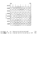
図8(a)は、印字ヘッドを駆動させるための駆動パルスを示した図であり、(b)は、その駆動パルスを生成するための基本クロックを示した図である。ここで、駆動パルスのパルス幅T0,T2,T4は、基本クロックの基本時間aを基準として、パーソナルコンピュータから送信されるパルス幅データHxの整数倍で設定され、パルス間隔T1,T3は、基本クロックの基本時間aを基準としてパルス間隔データLxの整数倍で設定されるものである。
【0005】
例えば、パルス幅8μsとパルス間隔30μsとからなる駆動パルスを基本時間0.1μsの基本クロックを基準として生成する場合、パーソナルコンピュータから送信されるパルス幅データHxは、8/0.1=80(1010000B)、即ち、7ビットのデータであり、パルス間隔データLxは、30/0.1=300(100101100B)、即ち、9ビットのデータである。
【0006】
次に、その7ビットからなるパルス幅データHx=(hx6,hx5,hx4,hx3,hx2,hx1,hx0)と、9ビットからなるパルス間隔データLx=(lx8,lx7,lx6,lx5,lx4,lx3,lx2,lx1,lx0)とで構成される駆動パルスデータがパーソナルコンピュータから送信され、インクジェットプリンタのメモリに記憶される状況を説明する。通常、各データは1バイト単位(8ビット単位)で処理されるので、各データは、パーソナルコンピュータからインクジェットプリンタへ8ビット単位で送信され、また、その送信されたデータはインクジェットプリンタのメモリに8ビット単位で書き込まれるものである。
【0007】
図9は、パーソナルコンピュータから送信された駆動パルスデータが、インクジェットプリンタのメモリに格納されている状況を示した模式図である。パーソナルコンピュータから送信される7ビットからなるパルス幅データH0=(h06,h05,h04,h03,h02,h01,h00)は、7ビットのパルス幅データH0と1ビットの空領域とからなる8ビット単位で送信され、インクジェットプリンタのメモリの0000H番地に1バイトのデータとして記憶される。一方、9ビットからなるパルス間隔データL0=(l08,l07,l06,l05,l04,l03,l02,l01,l00)は、8ビットのデータ(l07,l06,l05,l04,l03,l02,l01,l00)からなる第1パルス間隔データと、残りの1ビットのデータ(l08)及び7ビットの空領域からなる8ビット単位で構成される第2パルス間隔データとの2つに分けて送信され、インクジェットプリンタのメモリの0001番地及び0002H番地に2バイトのデータとして記憶される。
【0008】
そして、そのメモリに記憶された駆動パルスデータは、インクジェトプリンタに設けられたゲートアレイ(G/A)において、所定の基本時間の基本クロックにもとづき、図8(a)に示したような印字ヘッドを駆動させるための駆動パルスに生成される。こうして、生成された駆動パルスが印字ヘッドの圧電素子に印加されると、圧電素子の収縮により、印字ヘッドのインク室の容積が変化し、その変化によってインク室に貯留されているインクが印字ヘッドの各ノズルからインク滴として吐出され印刷が行われるのである。
【0009】
【発明が解決しようとする課題】
しかしながら、上述したように、インクジェットプリンタに9ビットからなるパルス間隔データを送信する場合には、9ビットのパルス間隔データを第1パルス間隔データと第2パルス間隔データとの2つに分けて送信するため、実質的には16ビット(2バイト)のデータを送信することとなり、パーソナルコンピュータからインクジェットプリンタへのデータの転送に長時間を要するという問題があった。また、その送信されたデータを記憶するメモリも16ビット(2バイト)消費されることになるため、大容量のメモリを搭載する必要があり、インクジェットプリンタの製造コストが増大するという問題点があった。
【0010】
本発明は、上述した問題を解決するためになされたものであり、送信手段から受信手段に送信されるデータの送信時間を短縮することができると共に、受信手段のメモリの消費容量を削減することができるデータ送信システムを提供することを目的としている。
【0011】
【課題を解決するための手段】
この目的を達成するために請求項1記載のデータ送信システムは、データを送信する送信手段と、その送信手段により送信されるデータを受信する受信手段とを備え、前記送信手段と受信手段とにおいて送信および受信データを第1の基本単位時間にもとづいて所定単位ごとに処理する。前記送信するデータは、パルス幅を規定するパルス幅データと、そのパルス幅データの出力間隔を規定するパルス間隔データとを有し、前記送信手段は、前記所定単位を越えるデータ量を有するパルス幅データ又はパルス間隔データを、その基本単位時間を前記第1の基本単位時間よりも大きい第2の基本単位時間としたときのデータ量であって前記所定単位内のデータ量に削減する削減手段を備えており、前記受信手段は、前記削減手段により削減されたパルス幅データ又はパルス間隔データを復号化する復号化手段を備えている。
【0012】
この請求項1記載のデータ送信システムによれば、送信手段と受信手段とにより送信および受信されるパルス幅データ又はパルス間隔データは、所定単位ごとに処理される。ここで、送信手段において、所定単位を越えるデータ量を有するパルス幅データ又はパルス間隔データを受信手段に送信する場合には、その所定単位を越えるデータ量を有するパルス幅データ又はパルス間隔データは、その基本単位時間を第1の基本単位時間よりも大きい第2の基本単位時間としたときのデータ量に変換される。即ち、パルスは、基本単位時間を基にしてパルス幅データ及びパルス間隔データのそれぞれの整数倍で設定されるものであるため、基本単位時間を大きくすることにより所定単位を越えるデータのデータ量を削減できる。従って、所定単位を越えるデータ量を有するパルス幅データ又はパルス間隔データを削減手段により所定単位内のデータ量に削減できる。そして、その削減手段により削減されたパルス幅データ又はパルス間隔データが受信手段に送信され、復号化される。
【0013】
請求項2記載のデータ送信システムは、請求項1に記載のデータ送信システムにおいて、前記パルス幅データとパルス間隔データとの一方は、前記所定の処理単位を越えないが、他方は前記所定の処理単位を越えるものであり、前記復号化手段は、前記第1の基本単位時間を構成する第1の基本クロックと、前記第2の基本単位時間を構成する第2の基本クロックとを入力し、その第1の基本クロックにもとづいて、前記所定の処理単位を越えないパルス幅データとパルス間隔データとの一方を処理し、第2の基本クロックにもとづいて、前記所定の処理単位を越えるパルス幅データとパルス間隔データとの他方を処理する。
【0014】
この請求項2記載のデータ送信システムによれば、請求項1に記載のデータ送信システムと同様に作用する上、所定の処理単位を越えないパルス幅データとパルス間隔データとの一方は、復号化手段によって入力される第1の基本単位時間を構成する第1の基本クロックにもとづいて処理される。一方、所定の処理単位を越えるパルス幅データとパルス間隔データとの他方は、第2の基本時間にもとづき、削減手段により所定の処理単位を越えないデータ量に削減され、その削減手段により削減されたパルス幅データとパルス間隔データとの他方は、復号化手段によって入力される第2の基本単位時間を構成する第2の基本クロックにもとづいて処理される。
【0015】
請求項3記載のデータ送信システムは、請求項2に記載のデータ送信システムにおいて、前記復号化手段は、前記第1の基本クロックを計数する第1の計数手段を有し、その計数値にもとづき、前記パルス幅データとパルス間隔データとの一方を復号化し、その第1の計数手段の計数に引き続いて前記第2の基本クロックを計数する第2の計数手段を有し、その計数値にもとづき、前記パルス幅データとパルス間隔データとの他方を復号化する。
【0016】
この請求項3記載のデータ送信システムによれば、請求項2に記載のデータ送信システムと同様に作用する上、所定単位を越えないパルス幅データとパルス間隔データとの一方は、第1の計数手段により計数される第1の基本クロックの計数値にもとづき復号化される。そして、その第1の計数手段の計数に引き続いて、所定単位を越えるパルス幅データとパルス間隔データとの他方は、第2の基本時間にもとづき、削減手段により所定の処理単位を越えないデータ量に削減され、その削減手段により削減されたパルス幅データとパルス間隔データとの他方は、第2の計数手段により計数される第2の基本クロックの計数値にもとづき復号化される。
【0017】
請求項4記載のデータ送信システムは、請求項1から3のいずれかに記載のデータ送信システムにおいて、前記削減手段は、前記データを除算または減算する手段である。
【0018】
請求項5記載のデータ送信システムは、請求項1または4に記載のデータ送信システムにおいて、前記復号化手段は、前記データを乗算または加算する手段である。
【0019】
請求項6記載のデータ送信システムは、請求項1から5のいずれかに記載のデータ転送システムにおいて、前記送信および受信するデータは、印字手段を駆動するためのパルスに関するデータである。
【0020】
請求項7記載のデータ削減プログラムは、データを送信する送信手段と、その送信手段により送信されるデータを受信する受信手段とを備え、前記送信手段と受信手段とにおいて送信および受信データを第1の基本単位時間にもとづいて所定単位ごとに処理するデータ送信システムにおいて、前記送信手段は、前記所定単位を越えるデータ量を有するパルス幅データ又はパルス間隔データを、その基本単位時間を、前記第1の基本単位時間よりも大きい第2の基本単位時間としたときのデータ量であって前記所定単位内のデータ量に削減する。
【0021】
この請求項7記載のデータ削減プログラムによれば、送信手段と受信手段とにより送信および受信されるパルス幅データ又はパルス間隔データは、所定単位ごとに処理される。ここで、送信手段において、所定単位を越えるデータ量を有するパルス幅データ又はパルス間隔データを受信手段に送信する場合には、その所定単位を越えるデータ量を有するパルス幅データ又はパルス間隔データは、その基本単位時間を第1の基本単位時間よりも大きい第2の基本単位時間としたときのデータ量に変換される。即ち、パルスは、基本単位時間を基にしてパルス幅データ及びパルス間隔データのそれぞれの整数倍の形式で形成されるものであるため、基本単位時間を大きくすることにより所定単位を越えるデータのデータ量を削減できる。従って、所定単位を越えるデータ量を有するパルス幅データ又はパルス間隔データを所定単位内のデータ量に削減できる。
【0022】
請求項8記載のデータ削減プログラムは、請求項7に記載のデータ削減プログラムにおいて、前記削減手段は、前記データを除算または減算する手段である。
【0023】
請求項9記載のデータ削減プログラムは、請求項7または8に記載のデータ削減プログラムにおいて、前記送信および受信するデータは、印字手段を駆動するためのパルスに関するデータである。
【0024】
【発明の実施の形態】
以下、本発明の好ましい実施例について、添付図面を参照して説明する。本実施例は、パーソナルコンピュータ(以下「PC」と略す)と、そのPCに接続されるインクジェットプリンタとで構成されるデータ転送システムを用いて説明する。図1は、PCとそのPCに接続されたインクジェットプリンタの内部構成を示した斜視図である。
【0025】
図1に示すように、このインクジェットプリンタ100は、例えば、シアン、マゼンタ、イエロー、ブラックの4色のカラーインクがそれぞれ充填されるインクカートリッジ61と、用紙62に印字するための印字ヘッド3とを備えるヘッドユニット63と、インクカートリッジ61およびヘッドユニット63が搭載されるキャリッジ64と、このキャリッジ64を直線方向に往復移動させる駆動ユニット65と、キャリッジ64の往復移動方向に延び、印字ヘッド3と対向配置されるプラテンローラ66と、パージ装置67とを備えている。
【0026】
駆動ユニット65は、キャリッジ64の下端部に配置されプラテンローラ66と平行に延びるキャリッジ軸71と、キャリッジ64の上端部に配置されキャリッジ軸71に平行に延びるガイド板72と、そのキャリッジ軸71とガイド板72との間であって、キャリッジ軸71の両端部に配置される2つのプーリー73および74と、これらのプーリー73および74の間に掛け渡されるエンドレスベルト75とからなる。
【0027】
そして、一方のプーリ73が、CRモータ506の駆動により正逆回転されると、そのプーリ73の正逆回転に伴って、エンドレスベルト75に接合されているキャリッジ64が、キャリッジ軸71およびガイド板72に沿って、直線方向に往復移動される。
【0028】
用紙62は、カラーインクジェットプリンタ100の側方に設けられた給紙カセット(図示せず)から給紙され、印字ヘッド3と、プラテンローラ66との間に導入されて、印字ヘッド3から吐出されるインクにより所定の印字がなされ、その後、排紙される。なお、図1においては、用紙62の給紙機構および排紙機構の図示を省略している。
【0029】
パージ装置67は、プラテンローラ66の側方に設けられ、ヘッドユニット63がリセット位置にある時に、印字ヘッド3に対向するように配置されている。このパージ装置67は、印字ヘッド3の後述する複数のノズルを覆うように当該ノズルの開口面に対し当接するパージキャップ81と、ポンプ82およびカム83と、インク貯留部84とを備えており、ヘッドユニット63が、リセット位置にある時に、印字ヘッド3のノズルをパージキャップ81で覆い、印字ヘッド3の内部に溜まる気泡などを含んだ不良インクを、カム83の駆動によりポンプ82によって吸引することにより、印字ヘッド3の回復を図るようにしている。なお、吸引された不良インクは、インク貯留部84に貯められる。
【0030】
パージ装置67におけるプラテンローラ66側の位置には、パージ装置67に隣接してワイパ部材86が配設されている。このワイパ部材86は、へら状に形成されており、キャリッジ64の移動に伴って、印字ヘッド3のノズル形成面を拭うものである。このワイパ部材86は、ノズル形成面を拭う場合に、矢印W方向へ突出され、ノズル形成面を拭わない場合に、反矢印W方向へと後退される。キャップ85は、インクの乾燥を防止するため、印字が終了するとリセット位置に戻されるキャリッジ64に搭載された印字ヘッド3の複数のノズルを覆うものである。
【0031】
インクジェットプリンタ100の背面には、セントロニクス・インターフェイス(I/F)27(図2参照)のコネクタ(図示せず)が設けられている。インクジェットプリンタ100は、このI/F27に接続されたケーブル30を介して、印刷データを送信するPC50と接続される。なお、インクジェットプリンタ100とPC50との接続は、ケーブル30に限られるものではなく、赤外線などの光信号により接続することも可能である。
【0032】
図2は、PC50とインクジェットプリンタ100との電気回路構成を示したブロック図である。PC50には、CPU40、ROM41、RAM42、ゲートアレイ43、セントロニクス・インターフェイス(I/F)44、ハードディスク装置45、フロッピィディスクドライブ(FDD)46を備えている。このうち、CPU40、ROM41、RAM42、ゲートアレイ43、及び、I/F44は、バスライン47により相互に接続されている。このバスライン47は、アドレスバス、データバス、及び、制御信号線などにより構成されている。
【0033】
CPU40は、ROM41に記憶されるプログラムや、ハードディスク装置45に記憶されているオペーレーションシステム(OS)及び各種のアプリケーションプログラム、更には、フロッピィディスクによりFDD46を介して供給されるプログラムに基づいて動作する演算装置であり、各種の情報処理を行うものである。ROM41は、CPU40を動作させる基本プログラムの他、各種のデータを記憶する書き換え不可能な不揮発性のメモリである。
【0034】
RAM42は、書き換え可能な揮発性のメモリであり、プリンタドライバ45aのロードエリア42aと、駆動パルスメモリ42bと、駆動パルスポインタ42cとを備えている。プリンタドライバ45aのロードエリア42aは、ハードディスク装置45に格納されているプリンタドライバ45aを、ハードディスク装置45からロードするためのエリアである。駆動パルスメモリ42bは、プリンタドライバ45aにより生成されるパルス幅データ及びパルス間隔データからなる駆動パルスデータを記憶するためのエリアである。
【0035】
駆動パルスポインタ43cは、駆動パルスデータを記憶する駆動パルスメモリ42bの位置を示すポインタであり、駆動パルスデータは、駆動パルスポインタ43cが示す駆動パルスメモリ42bの番地へ記憶される。この駆動パルスポインタ43cの値は、駆動パルスメモリ42bへ駆動パルスデータが書き込まれることにより「1」が加算され、1ラインの駆動パルスデータが、インクジェットプリンタ100へ送信されることにより「0」(クリア)にされる。なお、この駆動パルスデータを駆動パルスメモリ42bに格納する格納処理及びその格納された駆動パルスデータをインクジェットプリンタに送信する送信処理については、図3のフローチャートにおいて説明する。
【0036】
ハードディスク装置45は、PC50のオペレーションシステム(OS)や各種のアプリケーションプログラムを記憶する書き換え可能な大容量メモリであり、このハードディスク装置45には、プリンタドライバ45aが記憶されている。プリンタドライバ45aは、前記各種のアプリケーションにより作製される印刷データに基づき、印字ヘッド3を駆動させるための駆動パルスデータを生成すると共に、そのデータをインクジェットプリンタ100に送信するためのプログラムである。
【0037】
ゲートアレイ43は、CPU40とハードディスク装置45およびFDD46との間のインターフェイスとして機能するものである。I/F44は、このI/F44に接続されたケーブル30を介して、インクジェットプリンタ100と接続され、データの送受信が可能にされている。FDD46は、FDD46に装着されたフロッピィディスクに記憶されるプログラムを読み出したり、そのフロッピィディスクへプログラムやデータを書き込むためのドライブ装置である。
【0038】
一方、PC50と接続されるインクジェットプリンタ100には、CPU11、ROM12、RAM13、ゲートアレイ(G/A)22等を備えた本体側制御基板520と、キャリッジ基板210とを備えている。CPU11には、ユーザが印字の指示などを行うための操作パネル14、CRモータ506を駆動するためのモータ駆動回路15、LFモータ510を駆動するためのモータ駆動回路16、用紙62(図1参照)の先端を検出するペーパーセンサ17、キャリッジ64(図1参照)の原点位置を検出する原点センサ18などが接続されている。
【0039】
印字ヘッド3は、キャリッジ基板210に実装されたヘッドドライバ21(駆動回路)によって駆動され、印字ヘッド3とヘッドドライバ21とは、厚さ50〜150μmのポリイミドフィルムに銅箔配線パターンを形成したフレキシブル配線板により接続される。ヘッドドライバ21は、本体側制御基板520に実装されたゲートアレイ22を介して制御され、駆動パルスを各駆動素子に印加するものである。
【0040】
ゲートアレイ22には、キャリッジ64の位置を検出するためのエンコーダセンサ29が接続されている。CPU11と、ROM12、RAM13、及びゲートアレイ22とは、アドレスバス23およびデータバス24を介して接続されている。CPU11は、ROM12に予め記憶されたプログラムに従い、印字タイミング信号、リセット信号、周期を異にする第1の基本クロック信号113及び第2の基本クロック信号114(図5参照)の各信号をゲートアレイ22へ転送する。
【0041】
ゲートアレイ22は、PC50からセントロニクス・インターフェース27を介して転送されてくる駆動パルスデータを、イメージメモリ25に記憶させる。また、ゲートアレイ22は、印字タイミング信号およびエンコーダセンサ29からの制御信号に従い、イメージメモリ25に記憶されている駆動パルスデータに基づいて、印字ヘッド3を駆動させるための駆動パルスと、その駆動パルスと同期する転送クロックCLKと、ラッチ信号と、基本印字波形信号を生成するためのパラメータ信号と、一定周期で出力される噴射タイミング信号JETとを出力し、それら各信号を、ヘッドドライバ21が実装されたキャリッジ基板210側へ転送する。そして、ゲートアレイ22は、PC50からセントロニクス・インターフェース27を介して転送されてくるセントロニクス・データに基づいてセントロニクス・データ受信割込信号を生成し、その信号をCPU11へ転送する。ゲートアレイ22とキャリッジ基板210との間で通信される各信号は、両者を接続するハーネスケーブル28を介して転送される。ハーネスケーブル28は、フレキシブルケーブルで構成されている。なお、印字ヘッド3を駆動させるための駆動パルスの生成については、後述する。
【0042】
次に、上記のPC50とインクジェットプリンタ100とで構成されるデータ送信システムにおいて、PC50で実行される駆動パルスデータの格納および送信処理について、図3のフローチャートを参照して説明する。ここで、駆動パルスデータを構成するパルス幅データは7ビットで構成され、パルス間隔データは9ビットで構成されるものとする。また、インクジェットプリンタ100は、PC50から送信される駆動パルスデータを8ビット単位で処理するものとする。
【0043】
プリンタドライバ45aによって、各種のアプリケーションで作製される印刷データに基づき生成される駆動パルスデータは、まず、駆動パルスデータのうちパルス幅データであるか否かが判断され、パルス幅データであった場合には(S60:Yes)、駆動パルスポインタ42cの示す駆動パルスメモリ42bへパルス幅データが書き込まれる(S61)。パルス幅データが書き込まれると、次のデータの書き込みに備え、駆動パルスポインタの値に「1」が加算され(S62)、駆動パルスポインタ42cの示す駆動パルスメモリ42bの番地が変更される。
【0044】
次に、パルス幅データが書き込まれた場合、又は、パルス幅データでなかった場合には(S60:No)、パルス間隔データであるか否かが判断され、パルス間隔データであった場合には(S63:Yes)、パルス間隔データが整数例えば「2」で除算される(S64)。即ち、上記パルス幅データはそのまま書き込むことで、その単位時間をそのままとし、このパルス間隔データを1/2して書き込むことで、その単位時間を2倍とする。具体的には、パルス間隔データを下位桁1ビットシフトして9ビットのうちの最下位桁を削除し、8ビットで構成されるパルス間隔データが駆動パルスポインタ42cの示す駆動パルスメモリ42bに書き込まれる(S65)。こうして、8ビットで構成されるパルス間隔データが書き込まれるので、7ビットのパルス幅データと9ビットのパルス間隔データとから構成される駆動パルスデータは、16ビット(2バイト)で以後の処理がなされることになる。尚、シフトされたパルス間隔データが書き込まれた後は、更に、次のデータの書き込みに備え、駆動パルスポインタ42cの値に「1」が加算される(S66)。
【0045】
その後、1ラインの駆動パルスデータの書き込みが終了したか否かが判断され、1ラインの書き込みが終了した場合には(S67:Yes)、その書き込みが終了した1ラインのデータが、I/F44を介してインクジェットプリンタ100のイメージメモリ25に送信される(S68)。また、1ラインの駆動パルスデータを送信した後は、駆動パルスポインタ42cの値が「0」(クリア)にされる(S69)。そして、全駆動パルスデータの送信が完了した場合には(S70:Yes)、駆動パルスデータの格納および送信処理を終了する。尚、1ラインのデータの書き込みが終了していない場合(S67:No)、全駆動パルスデータの送信が完了していない場合には(S70:No)、S60からの処理が繰り返される。こうして、9ビットのパルス間隔データを、インクジェットプリンタ100に送信する場合には、8ビット(1バイト)の容量で送信することができる。
【0046】
図4(a)は、PC50から送信された駆動パルスデータが、インクジェットプリンタ100のイメージメモリ25に格納されている状況を示した模式図である。図3で説明したように、9ビットからなるパルス間隔データLx=(lx8,lx7,lx6,lx5,lx4,lx3,lx2,lx1,lx0)は、第0ビットのデータ(lx0)が削減され、8ビット(1バイト)からなるパルス間隔データLx=(lx8,lx7,lx6,lx5,lx4,lx3,lx2,lx1)としてイメージメモリ25に送信される。そして、インクジェットプリンタ100は、送信されるデータを8ビット(1バイト)単位でイメージメモリ25に記憶するので、例えば、パルス間隔データL0は、イメージメモリ25の0001H番地に記憶されることになる。従って、9ビットのデータとして記憶する場合に比べ、イメージメモリ25のメモリ消費容量を実質1バイト削減できる。
【0047】
また、本実施例においては、3つのパルス幅(ハイパルス)と2つのパルス間隔(ロウパルス)とからなる駆動パルスにより画像の1ドットを形成することを想定しているため、3バイトのパルス幅データH0,H1,H2が、それぞれイメージメモリ25の0000H番地,0002H番地,0004H番地に記憶され、2バイトのパルス間隔データL0,L1が、それぞれイメージメモリ25の0001H番地,0003H番地に記憶される。従って、画像の1ドットを形成する場合に、メモリの消費容量を2バイト削減することができる。尚、0005H番地以降のメモリには、パルス幅データからパルス間隔データが交互に5バイト単位で記憶されていく。そして、このイメージメモリ25に記憶された1ドットの画像を構成する5バイトの駆動パルスデータは、ゲートアレイ22により5バイト単位で、印字ヘッド3を駆動させるための駆動パルスを生成するために用いられる。
【0048】
次に、図5及び図6を参照して、上述したパルス幅データH0,H1,H2とパルス間隔データL0,L1とからなる駆動パルスデータにもとづき、ゲートアレイ22により復号化される駆動パルスについて説明する。図5は、駆動パルスを生成するゲートアレイ22の電気回路構成を示したブロック図である。図6は、ゲートアレイ22から出力される駆動パルスのタイミングチャートを示した図である。図5に示すように、ゲートアレイ22には、駆動パルス終了信号発生回路97、AND回路90、カウンタ91〜95、OR回路96を備えている。
【0049】
駆動パルス終了信号発生回路97は、吐出開始前において、駆動パルス終了信号をAND回路90に出力する回路であり、吐出開始前にはハイパルス(図6の112a参照)が信号線112をとおして出力されている。CPU11から吐出要求信号としてハイパルス101aが信号線115をとおして出力されると、駆動パルス終了信号発生回路97はロウパルス(図6の112b参照)を出力する。そして、カウンタ95からハイパルス(図6の111a参照)が信号線111をとおして出力されると、駆動パルス終了信号発生回路97は、ハイパルス(図6の112c参照)を信号線112をとおして出力する。こうして、次の吐出要求信号が出力されるまでハイパルスを出力し続ける。
【0050】
AND回路90は、CPU11から吐出要求信号として出力されるハイパルス(図6の101a参照)と、駆動パルス終了信号発生回路97から駆動パルス終了信号として出力されるハイパルス(図6の112a参照)との論理積をとり、カウンタ91にハイパルス(図6の102a参照)を出力する回路である(102)。
【0051】
カウンタ91〜95には、1ドットの印字ごとに1組の駆動パルスデータのパルス幅データH0,H1,H2およびパルス間隔データL0,L1がイメージメモリ25から信号線116をとおしてロードされる。また、カウンタ91,93,95には、第1の基本クロック113が信号線117をとおして入力され、カウンタ92,94には、第2の基本クロック114が信号線118をとおして入力される。
【0052】
カウンタ91は、イメージメモリ25からロードされたパルス幅データH0(図4参照)にもとづき、駆動パルスのパルス幅(図6の110a参照)を規定するものである。AND回路90から信号線102をとおしてハイパルス102aが出力されると、OR回路96にハイパルス(図6の103a参照)を信号線103をとおして出力する。そして、ハイパルス103aの出力を開始すると同時に、第1の基本クロック113の計数を開始して、その計数値がパルス幅データH0になると計数を終了し、ハイパルス103aを立ち下げ、ロウパルス(図6の103b参照)とする。こうして形成された所定幅のハイパルス103aはOR回路96から信号線110をとおして出力される。また、計数を終了するとカウンタ91はクリアにされ、ハイパルス104aを信号線104をとおしてカウンタ92に出力する。
【0053】
カウンタ92は、イメージメモリ25からロードされたパルス間隔データL0(図4参照)にもとづき、駆動パルスのパルス間隔(図6の110b参照)を規定するものである。カウンタ91からハイパルス104aが出力されると、第2の基本クロック114の計数を開始して、その計数値がパルス間隔データL0になると計数を終了する。計数が終了するとカウンタ92はクリアにされ、ハイパルス105aを信号線105をとおしてカウンタ93に出力する。
【0054】
ここで、図6に示すようにハイパルス105aを出力すると同時に、OR回路96は、後述するように、カウンタ93からのハイパルス106aを出力するため、所定のパルス間隔110bが形成される。
【0055】
カウンタ93は、イメージメモリ25からロードされたパルス幅データH1(図4参照)にもとづき、駆動パルスのパルス幅(図6の110c参照)を規定するものである。カウンタ92からハイパルス105aが出力されると、OR回路96にハイパルス106aを信号線106をとおして出力する。そのハイパルス106aの出力を開始すると同時に、第1の基本クロック113の計数を開始して、その計数値がパルス幅データH1になると計数を終了する。計数を終了すると同時にロウパルス(図6の106b参照)とする。こうして形成された所定幅のハイパルス106aはOR回路96から出力される。また、計数を終了するとカウンタ93はクリアにされ、ハイパルス107aを信号線107をとおしてカウンタ94に出力する。
【0056】
カウンタ94は、イメージメモリ25からロードされたパルス間隔データL1(図4参照)にもとづき、駆動パルスのパルス間隔(図6の110d参照)を規定するものである。カウンタ93からハイパルス107aが出力されると、第2の基本クロック114の計数を開始して、その計数値がパルス間隔データL1になると計数を終了する。計数が終了するとカウンタ94はクリアにされ、ハイパルス108aを信号線108をとおしてカウンタ95に出力する。
【0057】
ここで、図6に示すようにハイパルス108aを出力すると同時に、OR回路96は、後述するように、カウンタ95からハイパルス109aを出力するため、所定のパルス間隔110dが形成される。
【0058】
カウンタ95は、イメージメモリ25からロードされたパルス幅データH2(図4参照)にもとづき、駆動パルスのパルス幅(図6の110e参照)を規定するものである。カウンタ94からハイパルス108aが出力されると、OR回路96にハイパルス109aを信号線109をとおして出力する。そのハイパルス109aの出力を開始すると同時に、第1の基本クロック113の計数を開始して、その計数値がパルス幅データH2になると計数を終了する。計数を終了すると同時にロウパルス(図6の109b参照)を信号線109をとおして出力する。こうして形成された所定幅のハイパルス109aはOR回路96から出力される。また、計数を終了するとカウンタ95はクリアにされ、ハイパルス111aを信号線111をとおして駆動パルス終了信号発生回路97に出力する。
【0059】
以上のように、OR回路96は、カウンタ91〜95から順次出力されるハイパルス及びロウパルスの列、即ち、駆動パルスを信号線110をとおして出力する。また、図6に示すように、OR回路96から3つのハイパルス110a,110c,110dと2つのロウパルス110b,110dとからなる駆動パルスが出力された後の間隔110fは、吐出要求信号としてのハイパルス101bが出力されるタイミングによって規定される。そして、以降同様なサイクルが繰り返される。
【0060】
図7(a)は、上記のようにして形成された駆動パルスを示した図であり、(b),(c)はその駆動パルスを生成するための基本クロックを示した図である。カウンタ91,93,95において処理される7ビットで構成されているパルス幅データH0,H1,H2は、図(b)に示すような第1基本時間aを構成する第1の基本クロック113に基づき、それぞれ所望のパルス幅T0,T2,T3,に生成される。一方、当初、9ビットで構成されおりCP50において、そのデータ量が削減(図3のS64の処理参照)され8ビット(1バイト)で構成されているパルス間隔データL0,L1は、カウンタ92,94において、図(c)に示すような第2基本時間b(=2a)を構成する第2の基本クロック114に基づき、それぞれ所望のパルス間隔T1,T3に生成される。即ち、第2基本時間bは、第1基本時間aの2倍に設定されているため、1ビット右にシフトされ、データ量が1/2に削減されたパルス間隔データは、その第2基本時間bに基づき復号化される。従って、第2の基本クロックを構成する第2基本時間bは、所定単位を越えるデータ量を有するデータに対して、所定単位内のデータ量になるように設定されるものである。
【0061】
こうして、ゲートアレイ22において生成された駆動パルスは、ヘッドドライバ21を介して印字ヘッド3の圧電素子に印加され、印字ヘッド3の圧電素子に駆動パルスが印加されると、圧電素子の伸縮により、印字ヘッド3のインク室の容積が変化し、その変化によってインク室に貯留されているインクが印字ヘッド3の各ノズルからインク滴として吐出され印刷が行われるのである。
【0062】
以上説明したように、本実施例のPC50と、そのPC50に接続されるインクジェットプリンタ100とで構成されるデータ転送システムによれば、PC50により送信される9ビットのパルス間隔データを8ビット単位で処理する場合に、従来であれば、実質的には16ビット(2バイト)で送信されるパルス間隔データを、第0ビットのデータ(lx0)を削減して、8ビット(1バイト)のパルス間隔データとして送信する。従って、インクジェットプリンタ100に駆動パルスデータを短時間で送信することができる。また、インクジェットプリンタ100は、そのパルス間隔データを受信するので、そのパルス間隔データを記憶するイメージメモリ25の消費容量を削減することができる。
【0063】
以上、実施例に基づき本発明を説明したが、本発明は上記実施例に何ら限定されるものではなく、本発明の趣旨を逸脱しない範囲内で種々の改良変形が可能であることは容易に推察できるものである。なお、請求項1記載のデータ送信システムでは、削減手段として図3におけるS64の処理が該当する。
【0064】
本実施例においては、画像の1ドットを3つのパルス幅(ハイパルス)と2つのパルス間隔(ロウパルス)とからなる駆動パルスを生成するインクジッェトプリンタ100を想定しているため、5つのカウンタ91〜95を設けたが、カウンタの数は5つに限定されるものではない。
【0065】
また、本実施例においては、PC50から送信される9ビットで構成されるパルス間隔データを1ビットを右にシフトさせ、即ち、パルス間隔データのデータ量を1/2に除算して、インクジェットプリンタに送信するデータ量を削減する場合について説明した。しかしながら、データ量を削減する手段は除算に限られず、減算するように構成しても良い。また、削減されるデータ量も1/2には限られず、例えば、10ビットで構成されるパルス幅データ又はパルス間隔データのデータ量を8ビット以内のデータ量に削減して、その削減したデータ量に応じて基本時間を大きくするように構成しても良い。
【0066】
また、本実施例においては、データ量を1/2に削減して2倍の基本時間を有する第2の基本クロックにもとづき、復号化させる場合について説明した。しかしながら、復号化させる手段は第2の基本クロックを設けることには限られず、減算又は除算したデータ量を加算又は積算して復号化するように構成しても良い。
【0067】
【発明の効果】
請求項1記載のデータ送信システムによれば、所定単位を越えるデータ量を有するパルス幅データ又はパルス間隔データは、その基本単位時間を第1の基本単位時間よりも大きい第2の基本単位時間としたときのデータ量に変換されるので、所定単位を越えるデータを第1の基本単位時間をもとに復号化する場合に比べ、所定単位を越えるデータのデータ量を削減することができる。よって、所定単位を越えるデータ量を所定単位を越えないデータ量にまで削減できるように基本単位時間を設定すれば、受信手段へデータを効率よく送信することができ、送信手段から受信手段へのデータ送信時間を短縮することができるという効果がある。更に、受信手段は、データ量が削減されたデータを受信するので、受信手段のメモリを効率よく利用でき、搭載するメモリは少容量のメモリで足り、受信手段の製造コストを削減することができるという効果がある。
【0068】
請求項2記載のデータ送信システムによれば、請求項1に記載のデータ送信システムの奏する効果に加え、大きさの異なる2つの基本単位時間は、それぞれ第1の基本クロックと第2の基本クロックとにより構成されるので、大きさの異なる基本単位時間をそれぞれ容易に構成することができ、所定単位を越えないパルス幅データ又はパルス間隔データの一方と、所定単位を越えるパルス幅データ又はパルス間隔データの他方とをそれぞれに処理することができるという効果がある。
【0069】
請求項3記載のデータ送信システムによれば、請求項2に記載のデータ送信システムの奏する効果に加え、第1の基本クロックは第1の計数手段により計数され、第2の基本クロックは第2の計数手段により計数されるので、大きさの異なる基本単位時間を構成する第1の基本クロックと第2の基本クロックとをそれぞれに計数することができる。また、第1の計数手段の計数に引き続いて、第2の計数手段の計数が行われるので、所定単位を越えないパルス幅データ又はパルス間隔データの一方と、所定単位を越えるパルス幅データ又はパルス間隔データの他方とを交互に復号化することができるという効果がある。
【0070】
請求項4記載のデータ送信システムによれば、請求項1から3のいずれかに記載のデータ送信システムの奏する効果に加え、削減手段は、データを除算または減算する手段であるので、容易にデータ量の削減を行うことができる。
【0071】
請求項5記載のデータ送信システムによれば、請求項1または4に記載のデータ送信システムの奏する効果に加え、復号化手段は、データを乗算または加算する手段であるので、容易にデータの復号化を行うことができる。
【0072】
請求項6記載のデータ送信システムによれば、請求項1から5のいずれかに記載のデータ送信システムの奏する効果に加え、送信および受信するデータは、印字手段を駆動するためのパルスに関するデータであるので、送信手段から印字手段を駆動するためのパルスに関するデータを送信した後、印字手段を駆動させるまでの時間を短縮することができ、利用者にストレスを感じさせることなく短時間で印刷することができるという効果がある。
【0073】
請求項7記載のデータ削減プログラムによれば、所定単位を越えるデータ量を有するパルス幅データ又はパルス間隔データの基本単位時間は、前記所定単位を越えない場合の第1の基本単位時間よりも大きい第2の基本単位時間に変換されるので、所定単位を越えるデータを第1の基本単位時間をもとに復号化する場合に比べ、所定単位を越えるデータのデータ量を削減できる。よって、所定単位を越えるデータ量を所定単位を越えないデータ量にまで削減できるように基本時間を設定すれば、受信手段へデータを効率よく送信することができ、送信手段から受信手段へのデータ送信時間を短縮することができるという効果がある。更に、受信手段は、データ量が削減されたデータを受信するので、受信手段のメモリを効率よく利用でき、搭載するメモリは少容量のメモリで足り、受信手段の製造コストを削減することができるという効果がある。
【0074】
請求項8記載のデータ削減プログラムによれば、請求項7に記載のデータ削減プログラムの奏する効果に加え、削減手段は、データを除算または減算する手段であるので、容易にデータ量の削減を行うことができる。
【0075】
請求項9記載のデータ削減プログラムによれば、請求項7または8に記載のデータ削減プログラムの奏する効果に加え、送信および受信するデータは、印字手段を駆動するためのパルスに関するデータであるので、送信手段から印字手段を駆動するためのパルスに関するデータを送信した後、印字手段を駆動させるまでの時間を短縮することができ、利用者にストレスを感じさせることなく短時間で印刷することができる。
【図面の簡単な説明】
【図1】PCとそのPCに接続されたインクジェットプリンタの内部構成を示した斜視図である。
【図2】PCとインクジェトプリンタとの電気回路構成を示したブロック図である。
【図3】PC50で実行される駆動パルスデータの格納および送信処理のフローチャートである。
【図4】インクジェットプリンタのメモリにおける駆動パルスデータの格納状況を示した模式図である。
【図5】ゲートアレイ(G/A)の電気回路構成を示したブロック図である。
【図6】ゲートアレイ(G/A)から出力される駆動パルスのタイミングチャートを示した図である。
【図7】(a)は駆動パルスを示した図であり、(b),(c)はその駆動パルスを生成するための基本クロックを示した図である。
【図8】(a)は駆動パルスを示した図であり、(b)はその駆動パルスを生成するための基本クロックを示した図である。
【図9】従来のインクジェットプリンタのメモリにおける駆動パルスデータの格納状況を示した模式図である。
【符号の説明】
3 印字ヘッド(印字手段)
22 ゲートアレイ(G/A)(復号化手段)
25 イメージメモリ
42 RAM
42a プリンタドライバのロードエリア
42b 駆動パルスメモリ
42c 駆動パルスポインタ
45 ハードディスク装置45
45a プリンタドライバ(変換手段)
50 パーソナルコンピュータ(PC)(送信手段)
91,93,95 カウンタ(第1の計数手段)
92,95 カウンタ(第2の計数手段)
100 インクジェットプリンタ(受信手段)
113 第1の基本クロック
114 第2の基本クロック[0001]
BACKGROUND OF THE INVENTION
The present invention relates to a data transmission system and a data reduction program for the system, and in particular, can reduce the transmission time of data transmitted from the transmission means to the reception means and reduce the memory consumption capacity of the reception means. The present invention relates to a data transmission system and a data reduction program for the system.
[0002]
[Prior art]
Conventionally, for example, in a data transmission system including a personal computer as a transmission unit and an inkjet printer including a plurality of nozzles as a reception unit, print data created by the personal computer is transmitted to the inkjet printer, and the transmission is performed. Printing is performed based on the print data.
[0003]
Here, in recent years, in the ink jet printer, in order to print an image with a high resolution, it is required to reduce the size of the ink ejected from the nozzle. Therefore, by adopting a so-called multi-pulse drive system that applies a plurality of pulses to the piezoelectric element of the print head and forms a dot of an image by landing a plurality of ink droplets, a higher resolution gradation expression is achieved. The one that enables is popular. On the other hand, in a personal computer, an OS such as Windows incorporates print control software called a printer driver, and the printer driver generates drive pulse data for driving the print head based on the print data. To the inkjet printer. The transmitted drive pulse data is stored in the memory of the ink jet printer, and is generated as a drive pulse for driving the print head based on a basic clock having a predetermined basic time in the gate array (G / A). It is.
[0004]
FIG. 8A is a diagram showing a drive pulse for driving the print head, and FIG. 8B is a diagram showing a basic clock for generating the drive pulse. Here, the pulse widths T0, T2, and T4 of the drive pulses are set as integer multiples of the pulse width data Hx transmitted from the personal computer with reference to the basic time a of the basic clock, and the pulse intervals T1, T3 are the basic intervals. It is set as an integer multiple of the pulse interval data Lx with reference to the clock basic time a.
[0005]
For example, when a drive pulse having a pulse width of 8 μs and a pulse interval of 30 μs is generated based on a basic clock having a basic time of 0.1 μs, the pulse width data Hx transmitted from the personal computer is 8 / 0.1 = 80 ( 1010000B), that is, 7-bit data, and the pulse interval data Lx is 30 / 0.1 = 300 (100101100B), that is, 9-bit data.
[0006]
Next, the 7-bit pulse width data Hx = (hx6, hx5, hx4, hx3, hx2, hx1, hx0) and the 9-bit pulse interval data Lx = (lx8, lx7, lx6, lx5, lx4). A situation in which drive pulse data composed of lx3, lx2, lx1, lx0) is transmitted from the personal computer and stored in the memory of the inkjet printer will be described. Normally, each data is processed in 1-byte units (8-bit units). Therefore, each data is transmitted from the personal computer to the inkjet printer in 8-bit units, and the transmitted data is stored in the memory of the inkjet printer. It is written in bit units.
[0007]
FIG. 9 is a schematic diagram showing a situation where the drive pulse data transmitted from the personal computer is stored in the memory of the inkjet printer. 7-bit pulse width data H0 = (h06, h05, h04, h03, h02, h01, h00) transmitted from the personal computer is 8 bits composed of 7-bit pulse width data H0 and 1-bit empty area. The data is transmitted in units and stored as 1-byte data at
[0008]
Then, the drive pulse data stored in the memory is printed in the gate array (G / A) provided in the ink jet printer based on the basic clock of a predetermined basic time as shown in FIG. Is generated as a drive pulse for driving. Thus, when the generated drive pulse is applied to the piezoelectric element of the print head, the volume of the ink chamber of the print head changes due to the contraction of the piezoelectric element, and the ink stored in the ink chamber is changed by the change. Printing is performed by ejecting ink droplets from the nozzles.
[0009]
[Problems to be solved by the invention]
However, as described above, when transmitting 9-bit pulse interval data to the inkjet printer, the 9-bit pulse interval data is divided into two parts, the first pulse interval data and the second pulse interval data. Therefore, 16-bit (2 bytes) data is actually transmitted, and there is a problem that it takes a long time to transfer data from the personal computer to the inkjet printer. In addition, since the memory for storing the transmitted data also consumes 16 bits (2 bytes), it is necessary to install a large-capacity memory, which increases the manufacturing cost of the inkjet printer. It was.
[0010]
The present invention has been made to solve the above-described problem, and can reduce the transmission time of data transmitted from the transmission means to the reception means and reduce the memory consumption capacity of the reception means. It aims at providing the data transmission system which can do.
[0011]
[Means for Solving the Problems]
In order to achieve this object, the data transmission system according to claim 1 comprises transmission means for transmitting data, and reception means for receiving data transmitted by the transmission means, wherein the transmission means and the reception means The transmission and reception data are processed for each predetermined unit based on the first basic unit time. The data to be transmitted includes pulse width data defining a pulse width and pulse interval data defining an output interval of the pulse width data, and the transmitting means has a pulse width having a data amount exceeding the predetermined unit. Reduction means for reducing data or pulse interval data to a data amount that is a data amount when the basic unit time is a second basic unit time that is larger than the first basic unit time, and within the predetermined unit. The receiving means includes decoding means for decoding the pulse width data or the pulse interval data reduced by the reducing means.
[0012]
According to the data transmission system of the first aspect, the pulse width data or the pulse interval data transmitted and received by the transmission unit and the reception unit is processed for each predetermined unit. Here, in the transmission means, when transmitting pulse width data or pulse interval data having a data amount exceeding a predetermined unit to the receiving means, the pulse width data or pulse interval data having a data amount exceeding the predetermined unit is: The basic unit time is converted into a data amount when the second basic unit time is larger than the first basic unit time. In other words, since the pulse is set as an integer multiple of the pulse width data and the pulse interval data based on the basic unit time, the data amount of data exceeding a predetermined unit can be increased by increasing the basic unit time. Can be reduced. Therefore, pulse width data or pulse interval data having a data amount exceeding a predetermined unit can be reduced to a data amount within the predetermined unit by the reducing means. Then, the pulse width data or pulse interval data reduced by the reduction means is transmitted to the reception means and decoded.
[0013]
The data transmission system according to
[0014]
According to the data transmission system of the second aspect, the data transmission system operates in the same manner as the data transmission system of the first aspect, and one of the pulse width data and the pulse interval data not exceeding a predetermined processing unit is decoded. Processing is performed based on the first basic clock constituting the first basic unit time input by the means. On the other hand, the other of the pulse width data and the pulse interval data exceeding the predetermined processing unit is reduced to the data amount not exceeding the predetermined processing unit by the reducing means based on the second basic time, and reduced by the reducing means. The other of the pulse width data and the pulse interval data is processed based on the second basic clock constituting the second basic unit time input by the decoding means.
[0015]
A data transmission system according to a third aspect is the data transmission system according to the second aspect, wherein the decoding means has a first counting means for counting the first basic clock, and based on the count value. , Having second counting means for decoding one of the pulse width data and pulse interval data and counting the second basic clock subsequent to the counting of the first counting means, and based on the counted value The other of the pulse width data and the pulse interval data is decoded.
[0016]
According to the third aspect of the data transmission system, the same operation as that of the second aspect of the data transmission system is performed, and one of the pulse width data and the pulse interval data not exceeding the predetermined unit is the first count. Decoding is performed based on the count value of the first basic clock counted by the means. Subsequently to the counting by the first counting means, the other of the pulse width data and the pulse interval data exceeding the predetermined unit is based on the second basic time, and the data amount not exceeding the predetermined processing unit by the reducing means. The other of the pulse width data and the pulse interval data reduced by the reduction means is decoded based on the count value of the second basic clock counted by the second count means.
[0017]
A data transmission system according to a fourth aspect of the present invention is the data transmission system according to any one of the first to third aspects, wherein the reduction means is means for dividing or subtracting the data.
[0018]
The data transmission system according to claim 5 is the data transmission system according to claim 1 or 4, wherein the decoding means is means for multiplying or adding the data.
[0019]
A data transmission system according to a sixth aspect is the data transfer system according to any one of the first to fifth aspects, wherein the data to be transmitted and received is data relating to a pulse for driving the printing means.
[0020]
According to a seventh aspect of the present invention, there is provided a data reduction program comprising: a transmission unit that transmits data; and a reception unit that receives data transmitted by the transmission unit. The transmission unit and the reception unit receive first transmission and reception data. In the data transmission system for processing every predetermined unit based on the basic unit time, the transmitting means sets the basic unit time to the pulse width data or the pulse interval data having a data amount exceeding the predetermined unit as the first unit time. The data amount when the second basic unit time is larger than the basic unit time is reduced to the data amount within the predetermined unit.
[0021]
According to the data reduction program of the seventh aspect, the pulse width data or the pulse interval data transmitted and received by the transmission unit and the reception unit is processed for each predetermined unit. Here, in the transmission means, when transmitting pulse width data or pulse interval data having a data amount exceeding a predetermined unit to the receiving means, the pulse width data or pulse interval data having a data amount exceeding the predetermined unit is: The basic unit time is converted into a data amount when the second basic unit time is larger than the first basic unit time. That is, the pulse is formed in the form of integer multiples of the pulse width data and the pulse interval data based on the basic unit time. Therefore, by increasing the basic unit time, data of data exceeding a predetermined unit is obtained. The amount can be reduced. Therefore, pulse width data or pulse interval data having a data amount exceeding a predetermined unit can be reduced to a data amount within the predetermined unit.
[0022]
The data reduction program according to claim 8 is the data reduction program according to claim 7, wherein the reduction means is means for dividing or subtracting the data.
[0023]
A data reduction program according to a ninth aspect is the data reduction program according to the seventh or eighth aspect, wherein the data to be transmitted and received is data relating to a pulse for driving the printing means.
[0024]
DETAILED DESCRIPTION OF THE INVENTION
Hereinafter, preferred embodiments of the present invention will be described with reference to the accompanying drawings. This embodiment will be described using a data transfer system including a personal computer (hereinafter abbreviated as “PC”) and an ink jet printer connected to the PC. FIG. 1 is a perspective view showing an internal configuration of a PC and an ink jet printer connected to the PC.
[0025]
As shown in FIG. 1, the
[0026]
The
[0027]
When one pulley 73 is rotated forward and backward by driving the
[0028]
The
[0029]
The
[0030]
A
[0031]
A connector (not shown) of a Centronics interface (I / F) 27 (see FIG. 2) is provided on the back surface of the
[0032]
FIG. 2 is a block diagram showing an electric circuit configuration of the
[0033]
The
[0034]
The
[0035]
The drive pulse pointer 43c is a pointer indicating the position of the drive pulse memory 42b for storing the drive pulse data, and the drive pulse data is stored at the address of the drive pulse memory 42b indicated by the drive pulse pointer 43c. The value of the drive pulse pointer 43c is incremented by “1” when the drive pulse data is written to the drive pulse memory 42b, and “0” (1 line) when the drive pulse data of one line is transmitted to the
[0036]
The
[0037]
The
[0038]
On the other hand, the
[0039]
The print head 3 is driven by a head driver 21 (drive circuit) mounted on the
[0040]
An
[0041]
The
[0042]
Next, storage and transmission processing of drive pulse data executed by the
[0043]
If the drive pulse data generated by the
[0044]
Next, when pulse width data is written or not pulse width data (S60: No), it is determined whether or not it is pulse interval data. (S63: Yes), the pulse interval data is divided by an integer, for example, “2” (S64). That is, the unit time is left as it is by writing the pulse width data as it is, and the unit time is doubled by writing half the pulse interval data. Specifically, the pulse interval data is shifted by 1 bit, the least significant digit of 9 bits is deleted, and the pulse interval data composed of 8 bits is written in the drive pulse memory 42b indicated by the drive pulse pointer 42c. (S65). Thus, since the pulse interval data composed of 8 bits is written, the drive pulse data composed of 7-bit pulse width data and 9-bit pulse interval data is 16 bits (2 bytes) and the subsequent processing is performed. Will be made. After the shifted pulse interval data is written, “1” is further added to the value of the drive pulse pointer 42c in preparation for writing the next data (S66).
[0045]
Thereafter, it is determined whether or not the writing of the drive pulse data for one line is completed. If the writing for one line is completed (S67: Yes), the data of one line for which writing has been completed is the I / F 44. Is transmitted to the
[0046]
FIG. 4A is a schematic diagram illustrating a situation where the drive pulse data transmitted from the
[0047]
Further, in this embodiment, since it is assumed that one dot of an image is formed by a driving pulse having three pulse widths (high pulse) and two pulse intervals (low pulse), 3-byte pulse width data is used. H0, H1, and H2 are stored in
[0048]
Next, referring to FIG. 5 and FIG. 6, the drive pulse decoded by the
[0049]
The drive pulse end
[0050]
The AND
[0051]
The
[0052]
The
[0053]
The counter 92 defines the pulse interval (see 110b in FIG. 6) of the drive pulse based on the pulse interval data L0 (see FIG. 4) loaded from the
[0054]
Here, as shown in FIG. 6, simultaneously with the output of the
[0055]
The
[0056]
The counter 94 defines the pulse interval (see 110d in FIG. 6) of the drive pulse based on the pulse interval data L1 (see FIG. 4) loaded from the
[0057]
Here, as shown in FIG. 6, simultaneously with outputting the
[0058]
The
[0059]
As described above, the
[0060]
FIG. 7A shows the drive pulse formed as described above, and FIGS. 7B and 7C show the basic clock for generating the drive pulse. The pulse width data H0, H1, H2 composed of 7 bits processed in the
[0061]
Thus, the drive pulse generated in the
[0062]
As described above, according to the data transfer system composed of the
[0063]
The present invention has been described based on the embodiments. However, the present invention is not limited to the above-described embodiments, and various improvements and modifications can be easily made without departing from the spirit of the present invention. It can be guessed. In the data transmission system according to claim 1, the processing of S64 in FIG.
[0064]
In the present embodiment, it is assumed that the
[0065]
In this embodiment, the pulse interval data composed of 9 bits transmitted from the
[0066]
In the present embodiment, the case has been described in which the amount of data is reduced to ½ and decoding is performed based on the second basic clock having a double basic time. However, the means for decoding is not limited to the provision of the second basic clock, and the decoding may be performed by adding or integrating the subtracted or divided data amount.
[0067]
【The invention's effect】
According to the data transmission system of claim 1, the pulse width data or the pulse interval data having a data amount exceeding a predetermined unit has the basic unit time as a second basic unit time larger than the first basic unit time. Therefore, the data amount exceeding the predetermined unit can be reduced as compared with the case where the data exceeding the predetermined unit is decoded based on the first basic unit time. Therefore, if the basic unit time is set so that the data amount exceeding the predetermined unit can be reduced to the data amount not exceeding the predetermined unit, the data can be efficiently transmitted to the receiving means, and the data from the transmitting means to the receiving means can be transmitted. There is an effect that the data transmission time can be shortened. Furthermore, since the receiving means receives data with a reduced amount of data, the memory of the receiving means can be used efficiently, and a small amount of memory is sufficient for mounting, and the manufacturing cost of the receiving means can be reduced. There is an effect.
[0068]
According to the data transmission system of the second aspect, in addition to the effect achieved by the data transmission system of the first aspect, the two basic unit times having different sizes are the first basic clock and the second basic clock, respectively. Therefore, basic unit times of different sizes can be easily configured, and one of pulse width data or pulse interval data not exceeding a predetermined unit and pulse width data or pulse interval exceeding a predetermined unit can be configured. There is an effect that the other data can be processed separately.
[0069]
According to the data transmission system of the third aspect, in addition to the effect of the data transmission system of the second aspect, the first basic clock is counted by the first counting means, and the second basic clock is the second Therefore, the first basic clock and the second basic clock constituting the basic unit times having different sizes can be respectively counted. In addition, since the counting of the second counting means is performed following the counting of the first counting means, one of the pulse width data or the pulse interval data not exceeding the predetermined unit and the pulse width data or the pulse exceeding the predetermined unit. There is an effect that the other of the interval data can be decoded alternately.
[0070]
According to the data transmission system of the fourth aspect, in addition to the effect achieved by the data transmission system according to any one of the first to third aspects, the reduction means is means for dividing or subtracting data. The amount can be reduced.
[0071]
According to the data transmission system of the fifth aspect, in addition to the effect produced by the data transmission system according to the first or fourth aspect, since the decoding unit is a unit for multiplying or adding data, the data can be easily decoded. Can be made.
[0072]
According to the data transmission system of the sixth aspect, in addition to the effect exhibited by the data transmission system according to any one of the first to fifth aspects, the data to be transmitted and received is data relating to pulses for driving the printing means. Therefore, it is possible to shorten the time until the printing unit is driven after transmitting the data related to the pulse for driving the printing unit from the transmission unit, and the printing is performed in a short time without causing the user to feel stress. There is an effect that can be.
[0073]
According to the data reduction program of claim 7, the basic unit time of the pulse width data or the pulse interval data having a data amount exceeding a predetermined unit is larger than the first basic unit time when the predetermined unit is not exceeded. Since the data is converted into the second basic unit time, the amount of data exceeding the predetermined unit can be reduced as compared with the case where data exceeding the predetermined unit is decoded based on the first basic unit time. Therefore, if the basic time is set so that the data amount exceeding the predetermined unit can be reduced to the data amount not exceeding the predetermined unit, the data can be efficiently transmitted to the receiving means, and the data from the transmitting means to the receiving means can be transmitted. There is an effect that the transmission time can be shortened. Furthermore, since the receiving means receives data with a reduced amount of data, the memory of the receiving means can be used efficiently, and a small amount of memory is sufficient for mounting, and the manufacturing cost of the receiving means can be reduced. There is an effect.
[0074]
According to the data reduction program of the eighth aspect, in addition to the effect produced by the data reduction program of the seventh aspect, the reduction means is a means for dividing or subtracting data, so that the data amount is easily reduced. be able to.
[0075]
According to the data reduction program of the ninth aspect, in addition to the effect produced by the data reduction program of the seventh or eighth aspect, the data to be transmitted and received is data relating to pulses for driving the printing means. After transmitting data related to pulses for driving the printing unit from the transmission unit, the time until the printing unit is driven can be shortened, and printing can be performed in a short time without causing the user to feel stress. .
[Brief description of the drawings]
FIG. 1 is a perspective view showing an internal configuration of a PC and an ink jet printer connected to the PC.
FIG. 2 is a block diagram showing an electric circuit configuration of a PC and an inkjet printer.
FIG. 3 is a flowchart of drive pulse data storage and transmission processing executed by the
FIG. 4 is a schematic diagram illustrating a storage state of drive pulse data in a memory of an inkjet printer.
FIG. 5 is a block diagram showing an electric circuit configuration of a gate array (G / A).
FIG. 6 is a timing chart of drive pulses output from a gate array (G / A).
7A is a diagram showing a drive pulse, and FIGS. 7B and 7C are diagrams showing a basic clock for generating the drive pulse. FIG.
8A is a diagram showing a drive pulse, and FIG. 8B is a diagram showing a basic clock for generating the drive pulse.
FIG. 9 is a schematic diagram showing a storage state of drive pulse data in a memory of a conventional inkjet printer.
[Explanation of symbols]
3 Print head (printing means)
22 Gate array (G / A) (decoding means)
25 Image memory
42 RAM
42a Printer driver load area
42b Drive pulse memory
42c Driving pulse pointer
45
45a Printer driver (conversion means)
50 Personal computer (PC) (transmission means)
91, 93, 95 counter (first counting means)
92,95 counter (second counting means)
100 Inkjet printer (receiving means)
113 First basic clock
114 Second basic clock
Claims (9)
前記送信するデータは、パルス幅を規定するパルス幅データと、そのパルス幅データの出力間隔を規定するパルス間隔データとを有し、
前記送信手段は、前記所定単位を越えるデータ量を有するパルス幅データ又はパルス間隔データを、その基本単位時間を前記第1の基本単位時間よりも大きい第2の基本単位時間としたときのデータ量であって前記所定単位内のデータ量に削減する削減手段を備えており、
前記受信手段は、前記削減手段により削減されたパルス幅データ又はパルス間隔データを復号化する復号化手段を備えていることを特徴とするデータ送信システム。A transmission unit for transmitting data; and a reception unit for receiving data transmitted by the transmission unit. The transmission unit and the reception unit transmit and receive data at predetermined units based on a first basic unit time. In the data transmission system to process
The data to be transmitted has pulse width data defining a pulse width and pulse interval data defining an output interval of the pulse width data,
The transmission means has a data amount when pulse width data or pulse interval data having a data amount exceeding the predetermined unit is a second basic unit time larger than the first basic unit time. And having a reduction means for reducing the amount of data within the predetermined unit,
The data transmission system according to claim 1, wherein the receiving means includes decoding means for decoding the pulse width data or pulse interval data reduced by the reducing means.
前記復号化手段は、前記第1の基本単位時間を構成する第1の基本クロックと、前記第2の基本単位時間を構成する第2の基本クロックとを入力し、その第1の基本クロックにもとづいて、前記所定の処理単位を越えないパルス幅データとパルス間隔データとの一方を処理し、第2の基本クロックにもとづいて、前記所定の処理単位を越えるパルス幅データとパルス間隔データとの他方を処理することを特徴とする請求項1に記載のデータ送信システム。One of the pulse width data and the pulse interval data does not exceed the predetermined processing unit, while the other exceeds the predetermined processing unit,
The decoding means inputs a first basic clock constituting the first basic unit time and a second basic clock constituting the second basic unit time, and inputs the first basic clock to the first basic clock. First, one of the pulse width data and the pulse interval data not exceeding the predetermined processing unit is processed, and the pulse width data and the pulse interval data exceeding the predetermined processing unit are processed based on the second basic clock. The data transmission system according to claim 1, wherein the other is processed.
その第1の計数手段の計数に引き続いて前記第2の基本クロックを計数する第2の計数手段を有し、その計数値にもとづき、前記パルス幅データとパルス間隔データとの他方を復号化することを特徴とする請求項2記載のデータ送信システム。The decoding means has first counting means for counting the first basic clock, and based on the counted value, decodes one of the pulse width data and pulse interval data,
Subsequent to counting by the first counting means, there is provided second counting means for counting the second basic clock, and the other of the pulse width data and the pulse interval data is decoded based on the counted value. The data transmission system according to claim 2, wherein:
前記送信手段は、前記所定単位を越えるデータ量を有するパルス幅データ又はパルス間隔データを、その基本単位時間を、前記第1の基本単位時間よりも大きい第2の基本単位時間としたときのデータ量であって前記所定単位内のデータ量に削減することを特徴とするデータ削減プログラム。A transmission unit for transmitting data; and a reception unit for receiving data transmitted by the transmission unit. The transmission unit and the reception unit transmit and receive data at predetermined units based on a first basic unit time. In a data reduction program for a data transmission system to process
The transmission means uses pulse width data or pulse interval data having a data amount exceeding the predetermined unit as data when the basic unit time is a second basic unit time larger than the first basic unit time. A data reduction program for reducing the amount of data within the predetermined unit.
Priority Applications (2)
| Application Number | Priority Date | Filing Date | Title |
|---|---|---|---|
| JP2001130248A JP4211237B2 (en) | 2001-04-26 | 2001-04-26 | Data transmission system and data reduction program for the system |
| US10/115,911 US7051228B2 (en) | 2001-04-05 | 2002-04-05 | Data transmission system using equalized data streams indicative of lengths of time |
Applications Claiming Priority (1)
| Application Number | Priority Date | Filing Date | Title |
|---|---|---|---|
| JP2001130248A JP4211237B2 (en) | 2001-04-26 | 2001-04-26 | Data transmission system and data reduction program for the system |
Publications (2)
| Publication Number | Publication Date |
|---|---|
| JP2002328782A JP2002328782A (en) | 2002-11-15 |
| JP4211237B2 true JP4211237B2 (en) | 2009-01-21 |
Family
ID=18978656
Family Applications (1)
| Application Number | Title | Priority Date | Filing Date |
|---|---|---|---|
| JP2001130248A Expired - Fee Related JP4211237B2 (en) | 2001-04-05 | 2001-04-26 | Data transmission system and data reduction program for the system |
Country Status (1)
| Country | Link |
|---|---|
| JP (1) | JP4211237B2 (en) |
Families Citing this family (1)
| Publication number | Priority date | Publication date | Assignee | Title |
|---|---|---|---|---|
| JP7803144B2 (en) * | 2022-01-26 | 2026-01-21 | ブラザー工業株式会社 | Liquid ejection device, liquid ejection system, and program |
-
2001
- 2001-04-26 JP JP2001130248A patent/JP4211237B2/en not_active Expired - Fee Related
Also Published As
| Publication number | Publication date |
|---|---|
| JP2002328782A (en) | 2002-11-15 |
Similar Documents
| Publication | Publication Date | Title |
|---|---|---|
| CN1111118C (en) | Memory expansion circuit for ink jet print head identification circuit | |
| US6634736B2 (en) | Ink-jet recording head, circuit board for ink-jet recording head, ink-jet recording head cartridge, and ink-jet recording apparatus | |
| EP0678386B1 (en) | Printing head, and printer and printing method using the printing head | |
| JP4714344B2 (en) | Printer for incorporation in consumer electronic (CE) systems with restricted access | |
| CN109278410B (en) | Print head, ink jet printer and control method of print head | |
| US7084996B2 (en) | Recording device | |
| US6007181A (en) | Ink-jet printing apparatus and ink-jet printing method for reducing density unevenness in a printed image due to deviation of ink application position | |
| US6439687B1 (en) | Ink-jet printer and printing head driving method therefor | |
| JP3227282B2 (en) | Recording head unit and recording device | |
| JP4218083B2 (en) | Inkjet printer | |
| US6382755B1 (en) | Printhead and printing apparatus using printhead | |
| JP2810701B2 (en) | Ink jet recording head and ink jet recording apparatus | |
| JP4211237B2 (en) | Data transmission system and data reduction program for the system | |
| JP4211229B2 (en) | Data transmission system and data conversion program for the system | |
| JP3637468B2 (en) | Printer drive device and printer | |
| CN1079186A (en) | recording device | |
| JP2013082146A (en) | Recording apparatus and processing method thereof | |
| JP5019641B2 (en) | Element base of recording head, recording head, recording head cartridge, and recording apparatus | |
| EP0798663B1 (en) | Dot printer and printing method | |
| US9533494B2 (en) | Address architecture for fluid ejection chip | |
| US7051228B2 (en) | Data transmission system using equalized data streams indicative of lengths of time | |
| JP4532684B2 (en) | Inkjet recording device | |
| EP0899103B1 (en) | Ink jet apparatus and ink jet recorder | |
| JP3177576B2 (en) | Dot printer | |
| JP3713882B2 (en) | Inkjet head control device |
Legal Events
| Date | Code | Title | Description |
|---|---|---|---|
| A621 | Written request for application examination |
Free format text: JAPANESE INTERMEDIATE CODE: A621 Effective date: 20050926 |
|
| A977 | Report on retrieval |
Free format text: JAPANESE INTERMEDIATE CODE: A971007 Effective date: 20080922 |
|
| TRDD | Decision of grant or rejection written | ||
| A01 | Written decision to grant a patent or to grant a registration (utility model) |
Free format text: JAPANESE INTERMEDIATE CODE: A01 Effective date: 20081007 |
|
| A01 | Written decision to grant a patent or to grant a registration (utility model) |
Free format text: JAPANESE INTERMEDIATE CODE: A01 |
|
| A61 | First payment of annual fees (during grant procedure) |
Free format text: JAPANESE INTERMEDIATE CODE: A61 Effective date: 20081020 |
|
| FPAY | Renewal fee payment (event date is renewal date of database) |
Free format text: PAYMENT UNTIL: 20111107 Year of fee payment: 3 |
|
| R150 | Certificate of patent or registration of utility model |
Free format text: JAPANESE INTERMEDIATE CODE: R150 Ref document number: 4211237 Country of ref document: JP Free format text: JAPANESE INTERMEDIATE CODE: R150 |
|
| FPAY | Renewal fee payment (event date is renewal date of database) |
Free format text: PAYMENT UNTIL: 20111107 Year of fee payment: 3 |
|
| FPAY | Renewal fee payment (event date is renewal date of database) |
Free format text: PAYMENT UNTIL: 20121107 Year of fee payment: 4 |
|
| FPAY | Renewal fee payment (event date is renewal date of database) |
Free format text: PAYMENT UNTIL: 20131107 Year of fee payment: 5 |
|
| LAPS | Cancellation because of no payment of annual fees |