JP4210021B2 - Image signal processing apparatus and image signal processing method - Google Patents
Image signal processing apparatus and image signal processing method Download PDFInfo
- Publication number
- JP4210021B2 JP4210021B2 JP2000191068A JP2000191068A JP4210021B2 JP 4210021 B2 JP4210021 B2 JP 4210021B2 JP 2000191068 A JP2000191068 A JP 2000191068A JP 2000191068 A JP2000191068 A JP 2000191068A JP 4210021 B2 JP4210021 B2 JP 4210021B2
- Authority
- JP
- Japan
- Prior art keywords
- pixel data
- image
- threshold value
- signal processing
- pixel
- Prior art date
- Legal status (The legal status is an assumption and is not a legal conclusion. Google has not performed a legal analysis and makes no representation as to the accuracy of the status listed.)
- Expired - Lifetime
Links
- 238000012545 processing Methods 0.000 title claims description 164
- 238000003672 processing method Methods 0.000 title claims description 9
- 230000009467 reduction Effects 0.000 claims description 52
- 238000012937 correction Methods 0.000 claims description 43
- 238000003384 imaging method Methods 0.000 claims description 41
- 238000001514 detection method Methods 0.000 claims description 28
- 238000000034 method Methods 0.000 claims description 21
- 238000004364 calculation method Methods 0.000 claims description 20
- 230000035945 sensitivity Effects 0.000 claims description 10
- 238000011946 reduction process Methods 0.000 claims description 4
- 230000015654 memory Effects 0.000 description 20
- 238000007781 pre-processing Methods 0.000 description 14
- 238000006243 chemical reaction Methods 0.000 description 13
- 230000006870 function Effects 0.000 description 13
- 230000003287 optical effect Effects 0.000 description 13
- 230000006835 compression Effects 0.000 description 12
- 238000007906 compression Methods 0.000 description 12
- 230000007274 generation of a signal involved in cell-cell signaling Effects 0.000 description 12
- 239000004973 liquid crystal related substance Substances 0.000 description 10
- 238000012935 Averaging Methods 0.000 description 9
- 230000006837 decompression Effects 0.000 description 9
- 230000008569 process Effects 0.000 description 9
- 230000000875 corresponding effect Effects 0.000 description 8
- 238000003708 edge detection Methods 0.000 description 8
- 230000007246 mechanism Effects 0.000 description 7
- 238000010586 diagram Methods 0.000 description 5
- 239000011159 matrix material Substances 0.000 description 5
- 102100036464 Activated RNA polymerase II transcriptional coactivator p15 Human genes 0.000 description 4
- 101000713904 Homo sapiens Activated RNA polymerase II transcriptional coactivator p15 Proteins 0.000 description 4
- 229910004444 SUB1 Inorganic materials 0.000 description 4
- 230000015556 catabolic process Effects 0.000 description 4
- 239000003086 colorant Substances 0.000 description 4
- 238000006731 degradation reaction Methods 0.000 description 4
- 230000000694 effects Effects 0.000 description 4
- 238000003825 pressing Methods 0.000 description 4
- 238000012546 transfer Methods 0.000 description 4
- 230000001066 destructive effect Effects 0.000 description 3
- 238000005375 photometry Methods 0.000 description 3
- 230000004044 response Effects 0.000 description 3
- 230000003321 amplification Effects 0.000 description 2
- 239000003638 chemical reducing agent Substances 0.000 description 2
- 230000000295 complement effect Effects 0.000 description 2
- 230000002596 correlated effect Effects 0.000 description 2
- 125000004122 cyclic group Chemical group 0.000 description 2
- 230000006866 deterioration Effects 0.000 description 2
- 230000004069 differentiation Effects 0.000 description 2
- 238000003199 nucleic acid amplification method Methods 0.000 description 2
- 101100366707 Arabidopsis thaliana SSL11 gene Proteins 0.000 description 1
- 101100096719 Arabidopsis thaliana SSL2 gene Proteins 0.000 description 1
- 101100366560 Panax ginseng SS10 gene Proteins 0.000 description 1
- 101100366562 Panax ginseng SS12 gene Proteins 0.000 description 1
- 102100035586 Protein SSXT Human genes 0.000 description 1
- 101000662518 Solanum tuberosum Sucrose synthase Proteins 0.000 description 1
- 238000003705 background correction Methods 0.000 description 1
- 230000008859 change Effects 0.000 description 1
- 230000001276 controlling effect Effects 0.000 description 1
- 238000011156 evaluation Methods 0.000 description 1
- 239000000284 extract Substances 0.000 description 1
- 238000009499 grossing Methods 0.000 description 1
- 229910044991 metal oxide Inorganic materials 0.000 description 1
- 150000004706 metal oxides Chemical class 0.000 description 1
- 230000008520 organization Effects 0.000 description 1
- 238000013139 quantization Methods 0.000 description 1
- 238000005070 sampling Methods 0.000 description 1
- 239000004065 semiconductor Substances 0.000 description 1
- 230000001953 sensory effect Effects 0.000 description 1
- 230000009466 transformation Effects 0.000 description 1
- WFKWXMTUELFFGS-UHFFFAOYSA-N tungsten Chemical compound [W] WFKWXMTUELFFGS-UHFFFAOYSA-N 0.000 description 1
- 229910052721 tungsten Inorganic materials 0.000 description 1
- 239000010937 tungsten Substances 0.000 description 1
Images


Classifications
-
- G06T5/70—
-
- G—PHYSICS
- G06—COMPUTING; CALCULATING OR COUNTING
- G06T—IMAGE DATA PROCESSING OR GENERATION, IN GENERAL
- G06T5/00—Image enhancement or restoration
- G06T5/20—Image enhancement or restoration by the use of local operators
-
- G—PHYSICS
- G06—COMPUTING; CALCULATING OR COUNTING
- G06T—IMAGE DATA PROCESSING OR GENERATION, IN GENERAL
- G06T2207/00—Indexing scheme for image analysis or image enhancement
- G06T2207/20—Special algorithmic details
- G06T2207/20172—Image enhancement details
- G06T2207/20192—Edge enhancement; Edge preservation
Description
【0001】
【発明の属する技術分野】
本発明は、画像信号処理装置および画像信号処理方法に関し、たとえば、固体撮像装置、ディジタルカメラおよび画像入力装置等が扱う画像データに対するノイズ低減処理に適用して好適なものである。
【0002】
【従来の技術】
現在、メガピクセルと高画素化された固体撮像装置がディジタルカメラ等に搭載されている。このようなカメラで撮像すると、撮像画像にはランダムノイズが多く含まれてくるので、ノイズ低減処理が行われる。ノイズ低減処理には、一般的にローパスフィルタを用いることが多い。
【0003】
ノイズ低減処理には、特開平4-235472号公報に記載された撮像装置のようにメディアンフィルタ手段でメディアンフィルタ処理を行うことも提案されている。
【0004】
また、この他のノイズ低減処理としては、1画面以上のメモリを内蔵し、同じ画像を複数回取り込んで得られた画像の加算平均してノイズを除去する巡回型ノイズリデューサがある。
【0005】
【発明が解決しようとする課題】
ところで、撮像画像に対して常時前述したフィルタ処理を行うと、画像はこのノイズ低減のフィルタ処理により画像の解像度等の画質が低下してしまう。また、このフィルタ処理ではノイズ量の一律な低減化を行うが、撮影シーンや撮影モード等のノイズ量に対応した処理は、それぞれに対応したフィルタ、すなわち複数のフィルタを搭載することになり、現実的でなく困難であった。
【0006】
さらに、巡回型ノイズリデューサ(加算平均の方法)では、画像入力期間中、シーンが変化しないという前提において有効に機能することから、適用可能なシーンの限定だけでなく、複数の画像を取り込むメモリおよび繰返し撮像することから所要時間を通常の撮像より要することの問題点が挙げられる。これは、ディジタルカメラの機能を大きく損ねるものである。
【0007】
一方、撮像シーンの一つである夜景のような信号レベルの低いシーンを撮影する場合、ディジタルカメラは信号処理を行う際に感度アップ等のゲイン補正処理を行っている。このゲイン補正処理は、画像データのレベルを増幅するとともに、ノイズも増幅してしまう。
【0008】
ディジタルカメラ等の信号処理では、一般に、出力する画像の階調特性の補正に非線形なガンマ補正を施している。この補正は低輝度の範囲でより大きなゲイン補正を行っていることから、低輝度レベルでノイズを強調してしまう。このように撮影条件、各画素レベルごとに変化するノイズ量の問題点があった。
【0009】
本発明はこのような従来技術の欠点を解消し、撮影条件やレベルの変化に応じた適切なノイズ低減を行って良好な画像にすることのできる画像信号処理装置および画像信号処理方法を提供することを目的とする。
【0010】
【課題を解決するための手段】
本発明は上述の課題を解決するために、画像入力して得られた画像データに信号処理を施す画像信号処理装置において、この装置は、この画像データに対して補正、および記録用の信号処理を施すとともに、画像データのそれぞれに対して画像入力時の条件および/または画素レベルを考慮して前記画像データに対するノイズ低減処理を施す信号処理手段とを含み、信号処理手段は、画像入力時の条件および/または画素レベルを考慮してしきい値を生成するしきい値生成手段と、ノイズ低減処理においてノイズ検出対象の画素データとこの画素データの周辺近傍にある画素データの平均値とのレベル差を求め、このレベル差と設定したしきい値とからノイズ検出対象の画素データまたは平均値のいずれかの使用を判定し、この使用の判定結果に応じて使用する画素データを切り換えるノイズ低減手段とを含むことを特徴とする。
【0011】
本発明の画像信号処理装置は、信号処理手段で画像データの各画素に対してノイズ検出対象にし、しきい値生成手段で画像データのノイズ検出対象に対するしきい値の生成を行い、ノイズ低減処理手段ではこの対象の画素データと周辺の画素データの平均値とのレベル差から対象の画素データが周囲を平均した際のレベルに対して相対的にどの程度かを調べて、このレベル差がしきい値を基準に判定し、判定結果に応じて対象の画素データに対してこの画素データそのものまたは平均値のいずれかを切換選択することにより、画像入力条件に応じて画像におけるノイズを抑えて画質劣化の少ない画像を生成することができる。
【0012】
また、本発明は上述の課題を解決するために、画像入力により得られる画像データに信号処理を施して画像を生成する画像信号処理方法において、この方法は、画像入力を行う上で用いる画像入力条件を取得する第1の工程と、この取得した画像入力条件に基づいて画像データが含むノイズの低減処理を施す対象の画素の使用を判定するしきい値を算出する第2の工程と、対象の画素の周辺近傍の画素が有するレベルを用いてその平均値を算出する第3の工程と、対象の画素のレベルと前記平均値の差を算出する第4の工程と、このレベル差としきい値とを比較判定して使用する画素データをこの対象の画素データそのものを用いる場合と平均値を用いる場合のいずれか選択する第5の工程と、この対象の画素のレベルを選択した画素データにする第6の工程とを含むことを特徴とする。
【0013】
本発明の画像信号処理方法は、画像データの各画素に対してノイズ検出対象にし、この際にこの画素の周囲の画素の平均値を算出し、各対象の画素と平均値とのレベル差から対象の画素が相対的に周囲とどの程度にずれているかを求め、しきい値を基準にしきい値とレベル差とを比較判定し、レベル差が小さい場合ノイズ成分を多く含むおそれを考慮して平均値を用い、レベル差がしきい値以上の場合ノイズ成分より信号成分が大きいと判定して対象の画素レベルを用い、判定に応じた切換選択を行って画素データの置換をすることにより、画像入力条件に応じて画像に含まれるノイズによる画質劣化の少ない画像を生成することができる。
【0014】
【発明の実施の形態】
次に添付図面を参照して本発明による画像信号処理装置の一実施例を詳細に説明する。
【0015】
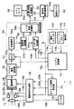
本発明と直接的に関係のない部分について図面および説明を省略する。ここで、信号の参照符号は、その現れる接続線の参照番号で表す。本実施例は、本発明の固体撮像装置を適用したディジタルカメラ10について説明する(図1を参照) 。ディジタルカメラ10には、光学レンズ系12、操作部14、システム制御部16、駆動信号生成部18、タイミング信号発生部20、絞り機構22、メカニカルシャッタ24、ストロボ26、撮像部28、アナログ信号処理部30、A/D 変換部32、信号処理部34、圧縮/伸張処理部36、メモリカード38、表示用信号処理部40および液晶モニタ42が備えられている。
【0016】
これら各部を順次説明する。光学レンズ系12は、たとえば、複数枚の光学レンズを組み合わせて構成されている。光学レンズ系12には、図示しないが、これら光学レンズの配置する位置を調節して画面の画角を操作部14からの操作信号14a に応じて調節するズーム機構や被写体とカメラ10との距離に応じてピント調節する、AF(Automatic Focus :自動焦点)調節機構が含まれている。操作信号14a は、たとえばレリーズボタン(図示せず)のストローク操作に応じてシステム制御部16に供給される。光学レンズ系12には、システム制御部16から供給される制御信号16a に基づくAF調節機構の駆動信号180 がレンズ駆動部(図示せず)から供給される。AF調節機構は供給される駆動信号180 に応じて光学レンズを光軸に沿って変位させて焦点を調節する。
【0017】
操作部14には、レリーズボタン140 だけでなく、たとえばモニタ画面に表示される項目を選択するカーソルを表示させ、このカーソル移動および選択を行う機能を有する操作スイッチ部142 がある。画面表示の領域を選択項目で隠されるから、表示画像と選択項目のいずれかの表示をオン/オフ切換えて表示させるようにしてもよい。操作部14におけるこのような選択には、たとえば十字キーおよび/または液晶表示部分に配したタッチパネルセンサ等を用いてもよい。
【0018】
項目やレベル補正操作に応じた選択を指示する操作スイッチ部142 には、選択キーおよび選択した指示を決定(または送出する)決定キーが含まれている。操作部14で選択された操作や設定に関する情報は操作信号14a によりシステム制御部16に報知される。レリーズボタン140 は、操作信号の一つであるシャッタチャンスを示すそのタイミング信号14b をシステム制御部16に出力する。
【0019】
システム制御部16は、たとえば CPU(Central Processing Unit :中央演算処理装置)を有する。システム制御部16には、ディジタルカメラ10の動作手順が書き込まれた ROM(Read Only Memory:読み出し専用メモリ)がある。システム制御部16は、たとえば、ユーザの操作にともなって操作部14から供給される操作信号14a, 14bとこの ROMの情報を用いて各部の動作を制御する制御信号16a, 16bを生成する。特に、この制御信号16a の生成は、前述した操作部14のレリーズボタン140 のストローク操作に応じて行われる。
【0020】
システム制御部16は、生成した制御信号16a を駆動信号生成部18およびタイミング信号発生部20に供給し、生成した制御信号16b をアナログ信号処理部30、A/D 変換部32、信号処理部34、以後、信号線が図示していないが圧縮/伸張処理部36、表示用信号処理部40およびモニタ42に供給している。これら各部は供給される制御信号16a, 16bに応じてそれぞれ制御される。
【0021】
さらに詳述すると、システム制御部16は、制御信号16a を、最適な露出を行わせる標準露出にするように複数のパラメータを調整して露出量を算出し、この露出量に応じて生成する。システム制御部16は、生成した制御信号16a を駆動信号生成部18およびタイミング信号発生部20に供給する。
【0022】
駆動信号生成部18には、図示しないがレンズ駆動部、絞り駆動部、シャッタ駆動部、撮像駆動部、およびストロボ駆動部が含まれている。レンズ駆動部は、駆動信号180 を出力して被写体が撮像面において最適な焦点として結像するように自動的に前述した光学レンズ系12を変位させている(自動焦点調節)。
【0023】
絞り駆動部には、たとえば標準露出を行う際の絞り値や露出補正等の露出に関する制御信号16a が供給され、制御信号16a に応じた駆動信号182 を絞り機構22に出力する。シャッタ駆動部には、後述するようにタイミング信号発生部20からタイミング信号20a が供給される。シャッタ駆動部は、供給されるタイミング信号20a に応じて駆動信号184 をメカニカルシャッタ24に出力する。メカニカルシャッタ24は駆動信号184 の供給タイミングに応じて駆動させている。
【0024】
撮像駆動部にはタイミング信号20b に応じて駆動信号186 を撮像部28に供給する。撮像駆動部には、図1にあらわに図示していないが電子シャッタパルス、信号電荷を読み出すフィールドシフトパルス、および電極構造を考慮して複数の位相に変位させて信号電荷を転送させるタイミング信号(垂直・水平)等が供給されている。撮像駆動部はこれらの信号をまとめて複数種類の垂直駆動信号および水平駆動信号を撮像部28に出力する。
【0025】
ストロボ駆動部には、レリーズボタン140 の2段押圧によるストローク操作がなされた際の指示(信号14b )によりシステム制御部16から制御信号16a が供給される。操作部14では操作スイッチ部142 でのストロボ発光の設定がオンになっている場合、システム制御部16はストロボの発光光量が決まっていることから、あらかじめ発光時の被写体との距離、絞り値、およびシャッタ速度を考慮して露出量に関する各パラメータを設定している。レリーズボタン140 の操作に同期して発光を促す駆動信号188 を生成し、ストロボ26に出力する。
【0026】
なお、図示していないがアナログ信号処理部30には、ゲイン調整信号として駆動信号が供給されている。
【0027】
タイミング信号発生部20は、制御信号16a に基づいてメカニカルシャッタ24および撮像部28を動作させる複数種類のタイミング信号を生成する回路を含む。タイミング信号発生部20は、生成したタイミング信号20a, 20bをそれぞれ駆動信号生成部18(図示していないシャッタ駆動部および撮像駆動部)に供給し、また、信号線を示していないが生成したタイミング信号をアナログ信号処理部30およびA/D 変換部32にも供給している。
【0028】
絞り機構22は、駆動信号生成部18からの駆動信号182 に応じて撮像部28に入射する光束が通る開口径を露出量に基づく絞りに合うように開口調節する機能を有する。絞り機構22は、上述したように駆動信号182 により動作するが、この動作は操作部14のレリーズボタン140 の第1段のストローク操作に応じて取り込んだ光量を基にシステム制御部16が生成した制御信号16a に依存して行われる。
【0029】
メカニカルシャッタ24は、撮像部28に入射光束が入射する期間を露出量に基づいて規定される開放時間に合うようにシャッタをオン/オフする機能を有する。メカニカルシャッタ24も駆動信号生成部18(図示しないシャッタ駆動部)からの駆動信号184 に応じて動作する。シャッタ駆動部は、上述したようにシステム制御部16が生成した制御信号16a に依存している。この場合、システム制御部16は制御信号16a を操作部14の2段押込みタイプのレリーズボタン140 の2段階まで大きくストローク操作したタイミングに応じて生成している。
【0030】
ストロボ26は電子閃光(エレクトリックフラッシュ)を発生させる装置である。ストロボ26はレリーズボタン140 の撮像のタイミング信号14b に同期して動作させる。ストロボ26はシステム制御部16にてあらかじめ発光を想定して発光量、被写体までの距離、感度等々を考慮して露出量が決められている。ストロボ26にも発光およびそのタイミングを報知する駆動信号188 が供給されている。
【0031】
撮像部28は、光学ローパスフィルタ28a 、色フィルタ28b 、および固体撮像素子28c が一体的に設けられたセンサである。このセンサには、CCD (Charge Coupled Device:電荷結合素子)が用いられている。撮像部28は、光学レンズ系12で結像された光学像が受光部の各撮像素子に到達した光量に応じた光電変換を行って出力信号29を出力する。撮像素子28c には、CCD やMOS (Metal Oxide Semiconductor :金属酸化型半導体)タイプの固体撮像デバイスが適用される。撮像部28では、供給される駆動信号186 に応じて光電変換によって得られた信号電荷を所定のタイミングとして、たとえば、垂直ブランキング期間にフィールドシフトにより垂直転送路に読み出され、この垂直転送路をラインシフトした信号電荷が水平転送路に供給され、この水平転送路を経た信号電荷が図示しない出力回路による電流/電圧変換によってアナログ電圧信号29にされ、アナログ信号処理部30に出力される。撮像部28では、CCD タイプでは信号電荷の読出しモードに応じた間引き読出しや全画素読出しが用いられる。
【0032】
また、色フィルタ28b には、原色または補色の色フィルタセグメントを複数用いて所定のパターンが撮像素子に対応してたとえば、単板で形成されるように配されている。カメラ10は、上述したモードに応じて所定の色パターンを考慮して信号電荷を読み出している。
【0033】
アナログ信号処理部30には、図示しないがCDS 部(Correlated Double Sampling:相関二重サンプリング; 以下CDS という)が含まれている。CDS 部には、たとえば、CCD 型の撮像素子を用いて、基本的にその素子により生じる各種のノイズをタイミング信号発生部からのタイミング信号によりクランプするクランプ回路と、タイミング信号により信号電荷をホールドするサンプルホールド回路を有する。CDS 部は、ノイズ成分を除去してA/D 変換部32に送る。
【0034】
A/D 変換部32は、供給されるアナログ信号30a の信号レベルを所定の量子化レベルにより量子化してディジタル信号32a に変換するA/D 変換器を有する。A/D 変換部32は、タイミング信号発生部20から供給される変換クロック等のタイミング信号(図示せず)により変換したディジタル信号32a を信号処理部34に出力する。
【0035】
信号処理部34には、前処理部34a 、記録用処理部34b 、しきい値生成部34c 、およびノイズ低減処理部34d が含まれている。前処理部34a は、供給される画像のうち、所定の領域の画素データ32a がもつレベルを検出するとともに、この画素データ32a に線形な信号処理を各種施す。信号処理を行う各種の補正項目には、黒レベル補正、白バランスのゲイン補正、シェーディング補正等がある。この線形処理を施した段階の画像データ44は、絵にならない、生データである。この画像データ44を繰返し読み出して信号処理を施すとき、前処理部34a にはフレームメモリを複数個配設するようにしているとよく、非破壊読出しタイプのメモリを用いることが好ましい。前処理部34a は、読み出した画像データ44を記録用処理部34b に送られる。
【0036】
また、前処理部34a は、たとえば色フィルタの色フィルタセグメントの配置を考慮して得られる画素データを用いてレベル検出も行う。レベル検出は画像の領域を分割した各領域に対して行う分割測光、画面の中央部近傍の領域を測光するAE(Automatic Exposure control)検出、被写体とカメラとの間の距離調整用AF(Automatic Focus control )検出、および白バランス調整用AWB (Automatic White Balance control)検出等を行う。これらの検出では色フィルタを介して画素データを出力することから直接的に輝度信号が得られない。そこで、色フィルタが原色の場合色G 、補色の場合色Mgを輝度信号とみなして扱ってもよい。前処理部は、図示していないが検出結果をシステム制御部16に供給している。
【0037】
記録用処理部34b は、記録用のレベル補正部、ガンマ補正部、補間処理部、色差マトリクス処理部、およびフレームメモリを有している(図示せず)。記録用処理部34b は、これらの処理をシステム制御部16からの制御信号16b に応じて行う。記録用処理部34b はレベル補正部で画像データにレベル補正を行い、この画像データを内蔵するルックアップテーブルに供給し、ルックアップテーブルから入力に対応する値を出力させてガンマ補正する。なお、ガンマ特性を細かく調整する場合、実際に演算によって補正するようにしてもよい。
【0038】
記録用処理部34b は、非線型処理を施した画像データを補間処理部に供給する。補間処理部は単板の色フィルタを用いている場合、色フィルタセグメントの色パターン配置した位置にしか色データが得られない。補間処理部はこの色パターンの隙間に対応する位置の各色データを実際に得られた画素データを用いて補間し、その際に、記録画像フォーマットの画素数に合わせて生成する。補間処理は、補間対象の画素に対して周囲の画素を用いて加算平均して行う。
【0039】
また、補間処理は、周囲の画素の相関係数に基づいて相関のある方向の画素を用いて補間するようにしてもよい。補間処理部は、三原色R, G, B の面(プレーン)データを作成する。補間処理部は、この面データを色差マトリクス処理部に供給する。色差マトリクス処理部は、供給された三原色R, G, B の面データから輝度信号Y および色差信号(R-Y), (B-Y) を作成する。色差マトリクス処理部は作成した画像の輝度および色差信号をフレームメモリに出力する。
【0040】
フレームメモリは、一時記憶した画像データ44を繰り返し読み出すことができる非破壊型メモリが連写等を考慮して複数配設されている。フレームメモリは、後段で行うノイズ低減処理の際の平均化等の処理に用いる画像データ46が繰返し供給されるために配設している。したがって、フレームメモリは、システム制御部16の制御を受けて、アドレス制御により間引き読出しも繰り返し行える。読み出した画像データ46がしきい値生成部34c およびノイズ低減処理部34d にそれぞれ供給されている。
【0041】
しきい値生成部34c には、しきい値算出部340 およびしきい値補正部342 が備えられている(図2を参照)。しきい値算出部340 には、システム制御部16に集めた撮影条件の各パラメータ16c が供給され、これらのパラメータに応じて撮像する画像(全体)に対するしきい値を算出する機能を有している。
【0042】
パラメータには、撮像感度、露出条件、撮影モード、シャープネス、光源種、操作、および/または表示倍率等がある。撮像感度には、使用時のISO (International Standardization Organization )感度/ASA (American Standards Association )感度/DIN (Deutsche Industrie Normen)感度のいずれかで表示された感度が用いられる。露出条件としては、絞り値、シャッタ速度(および/または電子シャッタ速度)がある。また、撮影モードには、夜景モード、通常モードにおける順光/逆光モード、夕景モード、連写等がある。
【0043】
シャープネスは、解像力およびコントラスト特性に依存する鮮鋭度で、感覚的な言葉として多用される。このような質的な評価を数値化してパラメータで表す。光源種は、用いる光源が何かをパラメータで示す。具体的には青空光、曇天、時間による太陽光(日出、日没の直前、後等)、写真電球、およびタングステンランプ等があり、対応するパラメータを設定する。操作には、たとえばストロボの使用の可否に応じた光量の露出値(すなわちガイドナンバ)を考慮したパラメータ設定を行う。最後に、表示倍率は、たとえば電子ズームの拡大/縮小率を用いる。
【0044】
しきい値算出部340 は、これらのパラメータを単独または組み合わせて用いてしきい値(レベル)を生成する。このしきい値は画面全体に対する基準値である。しきい値算出部340 は生成したしきい値48をしきい値補正部342 に供給する。しきい値補正部342 は、一つひとつの画素データがもつ、たとえば輝度レベルまたは色レベルに応じてしきい値を補正する機能を有する。
【0045】
本実施例における補正機能とは、供給される輝度レベルに応じてしきい値を補正する機能である。その具体的な一例として、非線型処理の一つであるガンマ補正処理を考慮した補正である。ガンマ補正は、一般的に入力レベルが小さい場合ゲインを大きくし、入力レベルが大きい場合ゲインを小さくする傾向にある。ゲインが大きい場合、入力信号に含まれるノイズも増幅される傾向が強くなる。しきい値補正部342 は、この点を考慮してしきい値算出部340 で算出したしきい値48を供給される画像データ46のうちの輝度データY を用いて可変する。
【0046】
すなわち、しきい値の補正は、ガンマ補正により低いレベルの輝度データY が増幅されている可能性があって、ノイズも多く含む傾向があることからしきい値48よりもしきい値を高めに設定する。逆に、高い輝度レベルY が供給されると、ガンマ補正はそれほど大きなゲインアップは行われない。したがって、ノイズのレベル増幅も小さいと考えられる。この場合、しきい値は低く設定する。しきい値の補正は、しきい値48を基準に所定の範囲で補正されることになる。補正されたしきい値50がノイズ低減処理部34d に供給される。
【0047】
なお、しきい値補正には、輝度データY を用いたがこのデータに限定されるものでなく、色データCr, Cbを用いてもよい。色データは、色の濃い領域でノイズが目立つ傾向にあるから、この領域にノイズ低減処理を施すと、ディジタルゲインアップのときノイズ低減の効果が得られる。
【0048】
ノイズ低減処理部34d は、ノイズ低減処理を施すとともに、エッジ検出を行ってエッジ部分には対象の画素データをそのまま用いて平均値を用いない処理を施す。描写する画像のエッジ部分をノイズとして除去しこの部分を平均値で埋めると、平滑化にともなって解像度が低下し、画像の画質劣化につながるからである。ノイズ低減処理部34d は、図3に示すように、画像データ46をエッジ検出部344 とノイズ低減部346 との両方に供給する。エッジ検出部344 は検出したエッジの位置に対するノイズ低減処理を禁止する禁止信号52(レベル“H " )をノイズ低減部346 に供給している。
【0049】
ノイズ低減部346 には、加算平均部3460、加算器3462、切換スイッチ3464、比較判定部3466、および論理和回路3468が備えられている。加算平均部3460は、画像データ46の対象の画素データに対して周囲に位置する複数の画素データのレベルを加算平均する演算機能を有している。加算平均値51は加算器3462の一端3462a および切換スイッチ3464の一端a 側に供給されている。
【0050】
加算器3462は、加算平均した結果51を一端3462a 側に減算入力させ、他端3462b に加算入力させている。加算器3462はあらわに図示していないがこのような入力により得られる差分値の絶対値(以下、単に差分値という)を生成する機能を有している。差分値53が比較判定部3466に供給される。
【0051】
切換スイッチ3464は、上述したように一端a 側に加算平均値51が供給され、他端b 側に対象の画素データ(すなわち、画像データ)46が供給されている。切換スイッチ3464には、論理和回路3468から切換信号55として供給されている。切換信号55がレベル"H "のとき切換スイッチ3464の端子b 側に切り換え、レベル"L "のとき、切換スイッチ3464の端子a 側に切り換えている。この切換処理により、ノイズの少ない画素データ54が得られる。
【0052】
比較判定部3466には、補正されたしきい値50と差分値53とが供給されている。比較判定部3466は、差分値53がしきい値50以上のレベルを示す際にレベル"H "を出力する。これ以外のとき比較判定部3466はレベル"L "を出力する。論理和回路3468は2入力の論理和演算処理を行う。論理和回路3468は、エッジ検出部344 からの出力および比較判定部3466からの出力がそれぞれ供給されている。論理和回路3468は、エッジ検出部344 または比較判定部3466からのレベル"H "が供給された際にレベル"H "の切換信号55を切換スイッチ3464に出力する。これ以外の場合、レベル"L "を出力する。
【0053】
ノイズ低減部346 は、個々の画像に対する補正されたしきい値50を用いて画像データ46に対する置換の有無を判定し、画像のノイズ低減を行う。輝度データY において低輝度側では平均値を採用する画素が多くなりノイズが抑えられ、高輝度側では対象の画素データそのものが用いられる傾向による画像データ54が生成される。ノイズ低減処理部34d の動作については、さらに後段で詳述するが、ノイズ低減処理部34d はこのように演算処理により補正されたしきい値50と比較判定して用いる画素データ46の対象の画素(自画素)または平均値のいずれか一方を決めて出力し、画像データ54を圧縮/伸張処理部36および表示用信号処理部40に出力する。
【0054】
なお、エッジ検出部344 は、たとえば代表的な微分処理を用い、この微分処理に基づいて得られた高域成分だけを取り出している。
【0055】
圧縮/伸張処理部36は、供給された1フレーム分の画像データ54(輝度データと色差データ)に、たとえば、直交変換を用いたJPEG(Joint Photographic Experts Group)規格での圧縮を施す回路と、この圧縮した画像を再び元のデータに伸張する回路とを有する。圧縮/伸張処理部36は、システム制御部16の制御信号16b により記録時には圧縮したデータ38a を図示しないメモリカードI/F 部を介してメモリカード38に記録させる。
【0056】
圧縮/伸張処理部36が伸張処理を行う場合、逆にメモリカード38から読み出したデータ36a をメモリカードI/F 部を介して圧縮/伸張処理部36に取り込んで処理する。ここで処理されたデータは、システム制御部16の制御により圧縮/伸張処理部36は、所要の順序で処理して、たとえば図示していないが記録用処理部34b のフレームメモリに伸張したデータを書き込む。メモリカード38には、たとえば、いわゆるスマートメディアやICカードのような記録媒体を用いる。
【0057】
表示用信号処理部40には、レベル補正部、および表示変換処理部が備えられている。表示レベル補正部は、システム制御部16からの制御信号16b に応じて行う。システム制御部16は、前処理部で検出したデータを考慮して制御信号16b を生成している。表示変換処理部はフレームメモリから読み出し液晶モニタ42に表示する画素数を読み出す。記録に対応して、たとえば画素1280×1024を320 ×240 と4分の1にする場合、フレームメモリをアドレス制御して間引き読出した画像データに対して信号処理を施す。
【0058】
また、表示変換処理部は、電子ズームで拡大/縮小表示する場合も領域に合わせて画像データを読み出し、補間/間引き等を行う補間処理機能も有する。表示変換処理部は、補間/間引き処理した画像データ40a を液晶モニタ42に供給する。
【0059】
液晶モニタ42は、システム制御部16の制御(図示せず)に応じて供給される輝度データおよび色差データ54の表示におけるタイミングを調整して表示する機能を有する。また、液晶モニタ42は三原色RGB のデータで表示させてもよい。
【0060】
次にディジタルカメラ10の動作について説明する(図5を参照)。電源投入して初期設定後、図示しないがモードの選択を行う。本実施例ではこのモード設定を撮影モードにする。これ以外の場合のモードを選択した場合、その選択したモードの手順に移行する。選択した撮影モードのうち、どんな撮影を行うか撮影モードの設定を行う(ステップS10 )。本実施例の説明では夜間モードを設定する。
【0061】
この選択したモードで被写界から取り込んだシーンに動画用の信号処理として間引き処理や表示用信号処理を施して液晶モニタ42に動画表示する(ステップS12 )。
【0062】
次に電源をオンのままにあるかどうかの判断を行う(ステップS14 )。電源がオン状態にある場合(YES )、予備の撮像に進む(ステップS16 へ)。また、電源がオフになっている場合(NO)、ディジタルカメラ10の動作を終了する。予備の撮像では、レリーズボタン140 を2段ストロークのうちの1段までの押圧操作により本撮像を行う前段の処理として撮像部28で測光を行う。この測光で得られた画像データは前処理部34a に供給される。前処理部34a では、得られた画像データ32a を基にレベル検出を行う。レベル検出は、色フィルタの色フィルタセグメント配置に依存した色を考慮する画像データおよび白黒的な画像データ等に分けて行われる。検出したレベルや各種の設定に関する情報がシステム制御部16に供給される。
【0063】
システム制御部16では、検出したレベルに基づいて露出量を算出する。露出量は、絞り量およびシャッタ速度をどのくらいにするかを示すパラメータである。夜景モードの設定においてストロボ発光を行う設定になっているかに応じて発光量および被写体との距離も考慮してシステム制御部16では露出量が決定されている。また、夜景モードの設定に応じて得られた撮像信号に対する増幅も行われる。
【0064】
システム制御部16は、演算により算出した結果やこの選択したモードに関し集めた情報のなかから、しきい値の算出に関わる条件(すなわち各種パラメータ)の情報16c をしきい値生成部34c に供給する(ステップS18 )。これにより、各条件の取得が行われる。
【0065】
これらのパラメータ16c はしきい値生成部34c のしきい値算出部340 に供給される。しきい値算出部340 では、これらのパラメータ16c を用いてしきい値の算出が行なわれる(ステップS20 )。このように予備の撮像にともなってしきい値をあらかじめ算出しておく。
【0066】
この後、ユーザがレリーズボタン140 を全押し状態にするストローク操作(2段の押圧操作)が行われたかどうか判断する(ステップS22 )。この操作が行われた場合(YES )、この本撮像の指示14b を受けてシステム制御部16は、撮像部28でたとえば、全画素読出しを行なって静止画の撮像を行う(ステップS24 )。この操作が行われなかった場合(NO)、動画表示に戻る(ステップS12 へ)。
【0067】
この静止画撮像は、色フィルタ28b により色分解された入射光を固体撮像素子28c で光電変換して信号電荷に変換し、読み出した撮像信号29をディジタル変換し、前処理部34a のフレームメモリ(図示せず)に出力するまでの処理である。上述の処理の各手順を簡単に説明すると、固体撮像素子28c は、得られた信号電荷を信号29としてアナログ信号処理部30に供給する。
【0068】
アナログ信号処理部30では、供給される信号29にゲイン調整を施し、A/D 変換部32に出力する。A/D 変換部32では、供給されるアナログ信号30a をディジタル信号32a に変換している。このディジタル信号32a は画像データとして信号処理部34の前処理部34a に供給される(静止画撮像工程)。
【0069】
供給された画像データ32a に対する画像信号処理を施す(サブルーチンSUB1)。画像信号処理は、信号処理における一連の処理を行って、ノイズの低減された画像にしている。この画像信号処理については後段でさらに説明する。生成された画像データ54が圧縮/伸張処理部36および表示用信号処理部40にそれぞれ供給される。
【0070】
表示用信号処理部40では、システム制御部16からの制御に応じて供給された画像データ54を液晶モニタ42に表示する画素数に合わせる間引き処理を行う。間引き処理された画像データ40a が液晶モニタ42に供給される。液晶モニタ42は、供給された画像データ40a を所定の時間モニタ上に表示する(ステップS26 )。個の表示により、ユーザはどのように被写体が撮像されたかの確認をすることができる。
【0071】
また、圧縮/伸張処理部36では、供給された画像データ54に対して、たとえばJPEG規格に基づく圧縮処理を施す(ステップS28 )。圧縮処理の施された画像データ36a が図示しないメモリカードインターフェースを介してメモリカード38に供給される。メモリカード38では供給される画像データ36a が図示していないがシステム制御部16の制御に応じてメモリカード38に記録される(ステップS30 )。この記録後、撮影モード設定に戻る(ステップS10 へ)。このように撮像時ディジタルカメラ10は動作している。
【0072】
次にディジタルカメラ10における画像信号処理を説明する(サブルーチンSUB1:図6を参照)。画像信号処理では、まず前処理部34a にて供給された画像データ32a をフレームメモリ(図示せず)に入力する(サブステップSS10)。連写の場合、各フレームメモリに撮像したシーンを入力する。入力した画像データ32a が非破壊型のフレームメモリを用いることにより、システム制御部16の制御に応じて読み出される。前処理部34a では、レベル検出および各種項目に対してそれぞれ補正処理が行なわれる。レベル検出結果は図示しないが信号線を介してシステム制御部16に供給される。また、補正処理した画像データ44は記録用処理部34b に供給される。
【0073】
システム制御部16では供給されるレベルから露出量の算出を行い、絞り値およびシャッタ速度を決定する。また、システム制御部16には、操作部14から供給される選択により設定した情報等が供給される。システム制御部16は、しきい値算出に関わるパラメータ16c をしきい値生成部34c に供給する。
【0074】
しきい値生成部34c では供給されるパラメータ16c を用いてしきい値算出部340 にて撮像した画像全体に対するしきい値を算出する(サブステップSS12)。したがって、しきい値は、カメラ撮影時の条件となるパラメータにより変化することになる。このしきい値はこれら複数のパラメータのそれぞれの影響を考慮して数値化される。
【0075】
なお、しきい値算出部340 は、信号処理部34に配設しているが、ここに配設が限定されるわけでなく、システム制御部16に配設してもよい。システム制御部16にしきい値算出部を設けると、前処理部34a で得られたレベル検出を用いて露出量の設定を信号処理部34で行っていることおよび設定した情報等がまとめられるからである。この場合、システム制御部16から算出したしきい値がしきい値補正部に供給される。
【0076】
しきい値生成部34c は、本実施例では後述する各画素データに対してしきい値補正を施す際に対応が取り易いと思料して、しきい値算出部340 およびしきい値補正部342 を有している。
【0077】
次に記録用処理部34b で画像データ44に対して各種の信号処理を施して輝度データY 、色差データ(R-Y), (B-Y) を生成する(サブステップSS14)。この記録用の信号処理は、さらに説明すると、順次レベル補正、ガンマ補正、および補間処理を施して三原色R, G, B のプレーンデータを生成する。そして、これらのプレーンデータを色差マトリクス処理部に供給して輝度信号Y 、色差信号(R-Y), (B-Y) を生成する。生成された輝度信号Y 、色差信号(R-Y), (B-Y) が画像データ46としてしきい値生成部34c およびノイズ低減処理部34d に供給される。以下の処理でこの出力信号46の形式を繰返し読み出す要求があるときには非破壊型のフレームメモリを用いてこのフレームメモリ(図示せず)に記憶させるとよい。
【0078】
次にしきい値生成部34c のしきい値補正部342 では、供給される画像データ46の各画素を用いてしきい値算出部340 から供給されるしきい値48に補正を施す(サブステップSS16)。しきい値の補正は、供給される画素の輝度レベル、または色差レベルに応じて行う。本実施例のように夜景モードの場合、輝度レベルが低いにもかかわらずノイズレベルが高いため目立ち易い傾向にあることがわかっている。また、輝度レベルが低いとき、ガンマ補正の影響を強く受けることも知られている。このような観点からしきい値の補正は、算出したしきい値よりも高めにする。一方、輝度レベルの高い画素に対するしきい値は算出したしきい値よりも低めに補正する。このようにして各画素ごとに補正したしきい値50をノイズ低減処理部34d に供給している。
【0079】
なお、しきい値補正を施す目安に輝度データのレベルを用いたが、このレベルに限定されるものでなく、色差データのレベルでもよい。実際に、色の濃い、すなわち色データのレベルが高いところでノイズが目立つ。この場合のノイズ発生傾向を考慮してしきい値を補正すると、後段で行うノイズ低減処理により一層ノイズ低減効果を発揮させることができる。特に、ディジタル的なゲインアップで効果を発揮する。
【0080】
ノイズ低減処理部34d では、エッジの領域を除いて、ノイズ低減対象の画素値(レベル)L46 とこの画素を含む周囲の画素の加算平均値LAV とのいずれか一方の値の選択を供給されるしきい値50を用いて判定する(ノイズ低減処理:サブステップSS18)。エッジの領域についてはエッジ検出部344 の検出結果52を用いる。
【0081】
このノイズ低減処理では、手順を簡単に説明すると、対象の画素値L46 と加算平均値LAV との差分値LDIFを算出する。ここで、差分値LDIFはずれの方向に関わりなく算出すると、差分の絶対値を用いるとよい。そして、この画素に対するしきい値50と差分値LDIFとを比較する。差分値LDIFがしきい値50よりも小さいとき対象の画素レベルが小さくてノイズを多く含む傾向があると推量されるから、加算平均値LAV を用いる。加算平均値LAV は平均することによりランダムなノイズ成分が抑え込まれている。また、差分値LDIFがしきい値50以上のとき周囲に対して信号レベルが十分に大きくS/N 比が高いと推量されるから、対象の画素値L46 をそのまま用いる。エッジ検出部344 がエッジ検出した場合の画素も対象の画素値L46 をそのまま用いる。
【0082】
より具体的に説明する(図7を参照)。たとえば、画像60内に斜めにエッジ境界62を有し、エッジ境界で分けられる領域60a, 60bについてノイズ低減処理を行う。領域60a はこの領域全体の平均した画像レベルが10、領域60b はこの領域全体の平均した画像レベルが50の場合とする。この例におけるノイズ低減処理では列方向の3画素を用い、この3画素の中央を対象の画素とする。
【0083】
領域60a の対象の画素に対する補正したしきい値50は通常のしきい値より高めにしたレベル=8とする。対象の画素値L46 =16、この対象を挟む上下2画素を含む3画素で平均すると、加算平均値LAV は(10+16+10)/3 から12が得られる。差分値LDIFは16−12=4である。差分値LDIFがしきい値50よりも小さいので、対象の画素はレベル16をレベル12に置換する。これにより、対象の画素に含まれるノイズ成分が抑制される。
【0084】
また、領域60b の対象の画素に対する補正したしきい値50は通常のしきい値より低めにしたレベル=5とする。対象の画素値L46 =60、この対象を挟む上下2画素を含む3画素で平均すると、加算平均値LAV は(78+60+64)/3 から67が得られる。差分値LDIFは|60−67|=7である。差分値LDIFがしきい値50以上なので、ノイズ成分が目立たないとして対象の画素はレベル60をそのまま用いる。このような手順でノイズ低減処理を各画素に対して行う。
【0085】
次にノイズ低減処理が画像データ46の1フレーム分すべてに対して終了したかどうかの判断を行う(サブステップSS20)。まだ1フレームの画像データ46に対してノイズ低減処理が1フレーム分終了していない場合(NO) 、画像データ46の次の対象の画素を読み出してこの処理を繰り返す(サブステップSS16へ戻る)。次の対象の画素を読出しは、システム制御部16の制御により行われる。また、1フレーム分すべて処理が終了した場合(YES )、リターンに移行してサブルーチンSUB1を終了する。このように動作させることにより、たとえば夜景モードのようにノイズの目立つモードであっても従来の画像のようなノイズっぽい画像でなく、かつ画質劣化の少ない高品質な画像を容易に得ることができる。
【0086】
ここで、周囲の画素を用いて算出する平均値に単純な加算平均(すなわち、重み係数0.5 )を利用しているが、周囲の画素に対する重み係数は0.5 に限定されず、各画素の位置に応じてそれぞれ異なる重み係数で乗算し平均してもよいことは言うまでもない。
【0087】
以上のように構成することにより、各種の撮影条件を考慮してしきい値を設定し、しきい値に対して画素そのものまたは平均値のいずれかを選択して画像を生成するので、ノイズ成分の少ない画像にすることができる。したがって、これまでの、たとえば夜景モードで撮影した画像に比べて高品質な画像を提供することができる。
【0088】
また、画素毎にしきい値を補正することにより、一層ノイズの抑制された、高画質な画像にすることができる。
【0089】
なお、本実施例は、ディジタルカメラに適用した場合について説明したが、この実施例に限定されるものでなく、画像入力条件を取得し、画像を生成する装置に適用しても同様にノイズ低減の効果を発揮させることができることは言うまでもない。
【0090】
【発明の効果】
このように本発明の画像信号処理装置によれば、信号処理手段で画像データの各画素に対してノイズ検出対象にし、しきい値生成手段で画像データのノイズ検出対象に対するしきい値の生成を行い、ノイズ低減処理手段ではこの対象の画素データと周辺の画素データの平均値とのレベル差から対象の画素データが周囲を平均した際のレベルに対して相対的にどの程度かを調べて、このレベル差がしきい値を基準に判定し、判定結果に応じて対象の画素データに対してこの画素データそのものまたは平均値のいずれかを切換選択して画素データの置換を行って、画像入力条件に応じて画像におけるノイズを抑えて画質劣化の少ない画像を生成することにより、どのような画像入力条件で撮像してもノイズの目立たない高画質な画像を得ることができる。
【0091】
また、本発明の画像信号処理方法によれば、画像データの各画素に対してノイズ検出対象にし、この際にこの画素の周囲の画素の平均値を算出し、各対象の画素と平均値とのレベル差から対象の画素が相対的に周囲とどの程度にずれているかを求め、しきい値を基準にしきい値とレベル差とを比較判定し、レベル差が小さい場合ノイズ成分を多く含むおそれを考慮して平均値を用い、レベル差がしきい値以上の場合ノイズ成分より信号成分が大きいと判定して対象の画素レベルを用い、判定に応じた切換選択を行って画素データの置換して、画像入力条件に応じて画像に含まれるノイズによる画質劣化の少ない画像を生成することにより、画像入力条件によらず常にノイズの目立たない高画質な画像を得ることがができる。
【図面の簡単な説明】
【図1】本発明の画像信号処理装置を適用したディジタルカメラの概略的な構成を示すブロック図である。
【図2】図1の信号処理部におけるしきい値生成部の構成を示すブロック図である。
【図3】図1の信号処理部におけるノイズ低減処理部の構成を示すブロック図である。
【図4】図3のノイズ低減部の構成を示すブロック図である。
【図5】図1のディジタルカメラの動作手順を説明するメインフローチャートである。
【図6】図5の画像信号処理(サブルーチンSUB1)の動作手順を説明するフローチャートである。
【図7】図5の画像信号処理におけるノイズ低減処理のより具体的な例を示す模式図である。
【符号の説明】
10 ディジタルカメラ
12 光学レンズ系
14 操作部
16 システム制御部
28 撮像部
32 A/D 変換部
34 信号処理部
36 圧縮/伸張処理部
42 液晶モニタ
34a 前処理部
34b 記録用処理部
34c しきい値生成部
34d ノイズ低減処理部[0001]
BACKGROUND OF THE INVENTION
The present invention relates to an image signal processing device and an image signal processing method, and is suitable for application to noise reduction processing for image data handled by a solid-state imaging device, a digital camera, an image input device, and the like.
[0002]
[Prior art]
Currently, solid-state imaging devices with megapixels and high pixels are mounted on digital cameras and the like. When an image is taken with such a camera, the picked-up image contains a lot of random noise, and noise reduction processing is performed. In general, a low-pass filter is often used for noise reduction processing.
[0003]
For noise reduction processing, it has also been proposed to perform median filter processing by median filter means as in the imaging device described in Japanese Patent Laid-Open No. 4-235472.
[0004]
As another noise reduction process, there is a cyclic noise reducer that incorporates a memory of one or more screens and removes noise by averaging the images obtained by capturing the same image multiple times.
[0005]
[Problems to be solved by the invention]
By the way, if the above-described filter processing is always performed on the captured image, the image quality such as the resolution of the image is deteriorated due to the noise reduction filter processing. In addition, this filter processing reduces the amount of noise uniformly, but the processing corresponding to the amount of noise such as shooting scenes and shooting modes is equipped with filters corresponding to each, that is, a plurality of filters. It was difficult and difficult.
[0006]
Furthermore, since the cyclic noise reducer (addition averaging method) functions effectively on the premise that the scene does not change during the image input period, not only the applicable scene but also a memory for capturing a plurality of images and There is a problem that it takes more time than normal imaging because of repeated imaging. This greatly impairs the function of the digital camera.
[0007]
On the other hand, when shooting a scene with a low signal level, such as a night scene, which is one of imaging scenes, the digital camera performs gain correction processing such as increasing sensitivity when performing signal processing. This gain correction process amplifies the level of image data and also amplifies noise.
[0008]
In signal processing of a digital camera or the like, generally, non-linear gamma correction is performed to correct gradation characteristics of an output image. Since this correction performs larger gain correction in the low luminance range, noise is emphasized at the low luminance level. As described above, there is a problem of the amount of noise that changes for each photographing level and each pixel level.
[0009]
The present invention provides an image signal processing apparatus and an image signal processing method capable of solving such drawbacks of the prior art and performing an appropriate noise reduction according to changes in photographing conditions and levels to obtain a good image. For the purpose.
[0010]
[Means for Solving the Problems]
In order to solve the above-mentioned problems, the present invention provides an image signal processing apparatus that performs signal processing on image data obtained by inputting an image. The apparatus performs signal processing for correcting and recording the image data. And signal processing means for performing noise reduction processing on the image data in consideration of conditions and / or pixel levels at the time of image input with respect to each of the image data, the signal processing means at the time of image input Threshold generation means for generating a threshold value in consideration of conditions and / or pixel levels, and levels of pixel data subject to noise detection in noise reduction processing and an average value of pixel data in the vicinity of the pixel data The difference is calculated, and the use of either the pixel data or the average value of the noise detection target is determined from this level difference and the set threshold value. Characterized in that it comprises a noise reduction means for switching the pixel data to be used in accordance with the.
[0011]
In the image signal processing apparatus of the present invention, the signal processing means makes each pixel of the image data a noise detection target, the threshold value generation means generates a threshold value for the noise detection target of the image data, and noise reduction processing In the means, the level difference between the target pixel data and the average value of the surrounding pixel data is examined to determine how much the target pixel data is relative to the level when the surroundings are averaged. Judgment is made based on the threshold value, and the pixel data itself or the average value is switched and selected for the target pixel data according to the determination result, thereby suppressing noise in the image according to the image input condition and image quality. An image with little deterioration can be generated.
[0012]
Further, in order to solve the above-described problems, the present invention provides an image signal processing method for generating an image by performing signal processing on image data obtained by image input. This method uses image input for performing image input. A first step of acquiring a condition, a second step of calculating a threshold value for determining use of a pixel to be subjected to noise reduction processing included in the image data based on the acquired image input condition, and a target A third step of calculating an average value using levels of pixels in the vicinity of the pixel of the pixel, a fourth step of calculating a difference between the level of the target pixel and the average value, and the level difference A fifth step of selecting pixel data to be used by comparing and determining a value, either using the target pixel data itself or using an average value, and pixel data selecting the level of the target pixel Characterized in that it comprises a sixth step of.
[0013]
In the image signal processing method of the present invention, each pixel of the image data is subject to noise detection, and at this time, an average value of pixels around this pixel is calculated, and a level difference between each target pixel and the average value is calculated. Find out how much the target pixel is relatively deviated from the surroundings, compare the threshold value with the level difference based on the threshold value, and consider the possibility of containing a lot of noise components if the level difference is small When the average value is used and the level difference is equal to or greater than the threshold value, it is determined that the signal component is larger than the noise component, the target pixel level is used, and the pixel data is replaced by performing switching selection according to the determination, An image with little image quality deterioration due to noise included in the image can be generated according to the image input condition.
[0014]
DETAILED DESCRIPTION OF THE INVENTION
Next, an embodiment of an image signal processing apparatus according to the present invention will be described in detail with reference to the accompanying drawings.
[0015]
Drawings and descriptions of parts not directly related to the present invention are omitted. Here, the reference number of the signal is represented by the reference number of the connecting line that appears. In this embodiment, a
[0016]
Each of these parts will be described sequentially. The
[0017]
The
[0018]
The
[0019]
The
[0020]
The
[0021]
More specifically, the
[0022]
The drive
[0023]
For example, a
[0024]
A
[0025]
The strobe drive unit is supplied with a
[0026]
Although not shown, the analog
[0027]
The timing
[0028]
The
[0029]
The mechanical shutter 24 has a function of turning the shutter on / off so that the period during which the incident light beam is incident on the
[0030]
The
[0031]
The
[0032]
Further, the
[0033]
Although not shown, the analog
[0034]
The A /
[0035]
The
[0036]
The
[0037]
The
[0038]
The
[0039]
In the interpolation process, interpolation may be performed using pixels in a correlated direction based on the correlation coefficient of surrounding pixels. The interpolation processing unit creates surface (plane) data of the three primary colors R, G, and B. The interpolation processing unit supplies this surface data to the color difference matrix processing unit. The color difference matrix processing unit creates a luminance signal Y and color difference signals (RY), (BY) from the supplied surface data of the three primary colors R, G, B. The color difference matrix processing unit outputs the luminance and color difference signals of the created image to the frame memory.
[0040]
In the frame memory, a plurality of non-destructive memories capable of repeatedly reading the temporarily stored
[0041]
The threshold
[0042]
The parameters include imaging sensitivity, exposure conditions, shooting mode, sharpness, light source type, operation, and / or display magnification. As the imaging sensitivity, the sensitivity displayed in any of ISO (International Standardization Organization) sensitivity / ASA (American Standards Association) sensitivity / DIN (Deutsche Industrie Normen) sensitivity at the time of use is used. Exposure conditions include aperture value and shutter speed (and / or electronic shutter speed). In addition, the shooting mode includes a night view mode, a normal light / backlight mode in the normal mode, an evening scene mode, continuous shooting, and the like.
[0043]
Sharpness is a sharpness that depends on resolution and contrast characteristics, and is often used as a sensory term. Such qualitative evaluation is expressed numerically and expressed as a parameter. The light source type indicates a light source used as a parameter. Specifically, there are blue sky light, cloudy sky, sunlight by time (sunlight, just before and after sunset, etc.), photographic light bulb, tungsten lamp, and the like, and corresponding parameters are set. For the operation, for example, parameter setting is performed in consideration of the exposure value (that is, the guide number) of the light amount according to whether or not the strobe is used. Finally, for example, an enlargement / reduction ratio of electronic zoom is used as the display magnification.
[0044]
The threshold
[0045]
The correction function in the present embodiment is a function for correcting the threshold value according to the supplied luminance level. As a specific example, the correction is in consideration of gamma correction processing which is one of nonlinear processing. The gamma correction generally tends to increase the gain when the input level is small and decrease the gain when the input level is large. When the gain is large, the noise included in the input signal tends to be amplified. In consideration of this point, the
[0046]
In other words, the threshold value correction is set higher than the
[0047]
Note that the luminance data Y was used for threshold correction, but the present invention is not limited to this data, and the color data C r , C b May be used. Since the color data has a tendency for noise to be conspicuous in a dark region, if noise reduction processing is performed on this region, the effect of noise reduction can be obtained when the digital gain is increased.
[0048]
The noise
[0049]
The
[0050]
The
[0051]
As described above, the
[0052]
The
[0053]
The
[0054]
Note that the
[0055]
The compression /
[0056]
When the compression /
[0057]
The display
[0058]
The display conversion processing unit also has an interpolation processing function for reading out image data in accordance with a region and performing interpolation / decimation or the like even when the image is enlarged / reduced by electronic zoom. The display conversion processing unit supplies the
[0059]
The liquid crystal monitor 42 has a function of adjusting and displaying the timing of display of luminance data and
[0060]
Next, the operation of the
[0061]
The scene captured from the object scene in the selected mode is subjected to thinning processing and display signal processing as moving image signal processing, and is displayed on the liquid crystal monitor 42 (step S12).
[0062]
Next, it is determined whether or not the power is kept on (step S14). If the power is on (YES), the process proceeds to preliminary imaging (go to step S16). If the power is off (NO), the operation of the
[0063]
The
[0064]
The
[0065]
These
[0066]
Thereafter, it is determined whether or not the user has performed a stroke operation (two-step pressing operation) for fully pressing the release button 140 (step S22). When this operation is performed (YES), the
[0067]
In this still image capturing, the incident light color-separated by the
[0068]
The analog
[0069]
Image signal processing is performed on the supplied
[0070]
The display
[0071]
Further, the compression /
[0072]
Next, image signal processing in the
[0073]
The
[0074]
The threshold
[0075]
Although the threshold
[0076]
In the present embodiment, the
[0077]
Next, the
[0078]
Next, the threshold
[0079]
Although the level of luminance data is used as a guideline for threshold correction, the level is not limited to this level and may be the level of color difference data. Actually, noise is conspicuous where the color is dark, that is, the color data level is high. If the threshold value is corrected in consideration of the noise generation tendency in this case, the noise reduction effect can be further exhibited by the noise reduction processing performed later. In particular, it is effective when digital gain is increased.
[0080]
In the noise
[0081]
In this noise reduction process, the procedure is briefly explained. 46 And addition average L AV Difference value L from DIF Is calculated. Where the difference value L DIF When calculating regardless of the direction of dislocation, the absolute value of the difference may be used. And the
[0082]
This will be described more specifically (see FIG. 7). For example, noise reduction processing is performed on
[0083]
The corrected
[0084]
Further, the corrected
[0085]
Next, it is determined whether or not the noise reduction processing has been completed for all frames of the image data 46 (substep SS20). If the noise reduction processing for one frame of
[0086]
Here, a simple addition average (that is, a weighting factor of 0.5) is used for the average value calculated using surrounding pixels, but the weighting factor for surrounding pixels is not limited to 0.5, and the position of each pixel is not limited. It goes without saying that the values may be multiplied and averaged by different weighting factors.
[0087]
By configuring as described above, a threshold value is set in consideration of various shooting conditions, and an image is generated by selecting either the pixel itself or the average value for the threshold value. The image can be reduced. Therefore, it is possible to provide a high-quality image as compared with the conventional image taken in the night view mode.
[0088]
Further, by correcting the threshold value for each pixel, it is possible to obtain a high-quality image in which noise is further suppressed.
[0089]
Although the present embodiment has been described with respect to a case where it is applied to a digital camera, the present invention is not limited to this embodiment, and noise reduction can be similarly applied to an apparatus that acquires image input conditions and generates an image. It goes without saying that the effects of can be demonstrated.
[0090]
【The invention's effect】
As described above, according to the image signal processing apparatus of the present invention, the signal processing means sets the noise detection target for each pixel of the image data, and the threshold value generation means generates the threshold value for the noise detection target of the image data. In the noise reduction processing means, from the level difference between the target pixel data and the average value of the surrounding pixel data, examine how much the target pixel data is relative to the level when the surroundings are averaged, This level difference is determined based on the threshold value, and pixel data is replaced by selecting either the pixel data itself or the average value for the target pixel data according to the determination result, and image input By generating images with little image quality degradation by suppressing noise in the image according to the conditions, it is possible to obtain a high-quality image with no noticeable noise regardless of the image input conditions Kill.
[0091]
Further, according to the image signal processing method of the present invention, each pixel of the image data is set as a noise detection target. At this time, an average value of pixels around this pixel is calculated, and each target pixel and the average value are calculated. The level difference of the target pixel is calculated to determine how far the target pixel is relative to the surroundings, and the threshold value and the level difference are compared and determined based on the threshold value. If the average value is taken into consideration, and the level difference is greater than or equal to the threshold value, it is determined that the signal component is larger than the noise component, the target pixel level is used, and the pixel data is replaced by performing switching selection according to the determination. Thus, by generating an image with little image quality degradation due to noise included in the image according to the image input condition, it is possible to obtain a high-quality image in which noise is not always noticeable regardless of the image input condition.
[Brief description of the drawings]
FIG. 1 is a block diagram showing a schematic configuration of a digital camera to which an image signal processing apparatus of the present invention is applied.
2 is a block diagram illustrating a configuration of a threshold value generation unit in the signal processing unit of FIG. 1;
FIG. 3 is a block diagram illustrating a configuration of a noise reduction processing unit in the signal processing unit of FIG. 1;
4 is a block diagram illustrating a configuration of a noise reduction unit in FIG. 3;
FIG. 5 is a main flowchart for explaining the operation procedure of the digital camera of FIG. 1;
6 is a flowchart illustrating an operation procedure of image signal processing (subroutine SUB1) in FIG. 5;
7 is a schematic diagram showing a more specific example of noise reduction processing in the image signal processing of FIG. 5. FIG.
[Explanation of symbols]
10 Digital camera
12 Optical lens system
14 Operation unit
16 System controller
28 Imaging unit
32 A / D converter
34 Signal processor
36 Compression / decompression processor
42 LCD monitor
34a Pre-processing section
34b Recording processing unit
34c Threshold generator
34d Noise reduction processor
Claims (8)
該画像データに対して補正、および記録用の信号処理を施すとともに、前記画像データのそれぞれに対して画像入力時の条件および/または画素レベルを基に前記画像データに対するノイズ低減処理を施す信号処理手段とを含み、
前記信号処理手段は、前記画像入力時の条件および/または前記画素レベルを基にしきい値を生成するしきい値生成手段と、
前記ノイズ低減処理においてノイズ検出対象の画素データと該画素データの周辺近傍にある画素データの平均値とのレベル差を求め、該レベル差と設定したしきい値とから前記ノイズ検出対象の画素データまたは前記平均値のいずれかの使用を判定し、該使用の判定結果に応じて使用する画素データを切り換えるノイズ低減手段とを含み、
前記ノイズ低減手段は、ノイズ検出対象の画素データと該画素データの周辺近傍の画素データのレベル差を算出するレベル差算出手段と、
前記周辺近傍の画素データの平均値を算出する平均値算出手段と、
該レベル差と設定したしきい値とから前記ノイズ検出対象の画素データまたは前記平均値のいずれかの使用を判定する比較判定手段と、
該使用の判定結果に応じて使用する画素データを切り換える画素切換手段とを含み、
さらに、前記平均値算出手段は、前記周辺近傍の画素データに対して該画素データの位置に応じてそれぞれ異なる重み係数を掛けて平均値を算出することを特徴とする画像信号処理装置。In an image signal processing apparatus that performs signal processing on image data obtained by inputting an image, the apparatus includes:
Signal processing for performing correction and recording signal processing on the image data, and applying noise reduction processing to the image data based on conditions and / or pixel levels at the time of image input for each of the image data Means,
The signal processing means includes a threshold value generating means for generating a threshold value based on the condition at the time of image input and / or the pixel level;
In the noise reduction processing, a level difference between pixel data subject to noise detection and an average value of pixel data in the vicinity of the pixel data is obtained, and the pixel data subject to noise detection is determined from the level difference and a set threshold value. or to determine the use of one of the average value, look including a noise reducing means for switching the pixel data to be used in accordance with the determination result of said use,
The noise reduction means includes level difference calculation means for calculating a level difference between pixel data subject to noise detection and pixel data in the vicinity of the pixel data;
An average value calculating means for calculating an average value of pixel data in the vicinity of the periphery;
Comparison determination means for determining use of the pixel data of the noise detection target or the average value from the level difference and the set threshold value;
Pixel switching means for switching pixel data to be used according to the use determination result,
Further, the average value calculating means calculates an average value by multiplying pixel data in the vicinity of the periphery by different weighting factors according to the positions of the pixel data .
該取得した条件に基づいて前記しきい値の算出を行うしきい値算出手段とを含むことを特徴とする画像信号処理装置。2. The apparatus according to claim 1, wherein the threshold value generation means acquires condition conditions for the threshold value;
An image signal processing apparatus comprising: threshold value calculation means for calculating the threshold value based on the acquired condition.
前記画像入力を行う上で用いる画像入力条件を取得する第1の工程と、
該取得した画像入力条件に基づいて前記画像データが含むノイズの低減処理を施す対象の画素の使用を判定するしきい値を算出する第2の工程と、
前記対象の画素の周辺近傍の画素が有するレベルを用いてその平均値を算出する第3の工程と、
前記対象の画素のレベルと前記平均値の差を算出する第4の工程と、
該レベル差と前記しきい値とを比較判定して使用する画素データを該対象の画素データそのものを用いる場合と前記平均値を用いる場合のいずれか選択する第5の工程と、
該対象の画素のレベルを前記選択した画素データにする第6の工程とを含み、
第3の工程は、前記周辺近傍の画素データに対して該画素データの位置に応じてそれぞれ異なる重み係数を掛けて平均値を算出することを特徴とする画像信号処理方法。In an image signal processing method for generating an image by performing signal processing on image data obtained by image input, the method includes:
A first step of acquiring image input conditions used in performing the image input;
A second step of calculating a threshold value for determining use of a pixel to be subjected to noise reduction processing included in the image data based on the acquired image input condition;
A third step of calculating an average value using a level of pixels in the vicinity of the target pixel; and
A fourth step of calculating a difference between the level of the target pixel and the average value;
A fifth step of selecting pixel data to be used by comparing and determining the level difference and the threshold value, using either the target pixel data itself or the average value;
Look including a sixth step of the level of the pixel of the object in the selected pixel data,
In the third step, an average value is calculated by multiplying the pixel data in the vicinity of the periphery by different weighting coefficients according to the positions of the pixel data .
該画像データに対して補正、および記録用の信号処理を施すとともに、前記画像データのそれぞれに対して画像入力時の条件および/または画素レベルを基に前記画像データに対するノイズ低減処理を施す信号処理手段とを含み、
前記信号処理手段は、前記画像入力時の条件および/または前記画素レベルを基にしきい値を生成するしきい値生成手段と、
前記ノイズ低減処理においてノイズ検出対象の画素データと該対象の画素データを含めた周辺近傍にある画素データの平均値とのレベル差を求め、該レベル差と設定したしきい値とから前記ノイズ検出対象の画素データまたは前記平均値のいずれかの使用を判定し、該使用の判定結果に応じて使用する画素データを切り換えるノイズ低減手段とを含み、
前記ノイズ低減手段は、ノイズ検出対象の画素データと該画素データの周辺近傍の画素データのレベル差を算出するレベル差算出手段と、
前記周辺近傍の画素データの平均値を算出する平均値算出手段と、
該レベル差と設定したしきい値とから前記ノイズ検出対象の画素データまたは前記平均値のいずれかの使用を判定する比較判定手段と、
該使用の判定結果に応じて使用する画素データを切り換える画素切換手段とを含み、
さらに、前記平均値算出手段は、前記周辺近傍の画素データに対して該画素データの位置に応じてそれぞれ異なる重み係数を掛けて平均値を算出することを特徴とする画像信号処理装置。In an image signal processing apparatus that performs signal processing on image data obtained by inputting an image, the apparatus includes:
Signal processing for performing correction and recording signal processing on the image data, and applying noise reduction processing to the image data based on conditions and / or pixel levels at the time of image input for each of the image data Means,
The signal processing means includes a threshold value generating means for generating a threshold value based on the condition at the time of image input and / or the pixel level;
In the noise reduction process, a level difference between pixel data subject to noise detection and an average value of pixel data in the vicinity of the periphery including the target pixel data is obtained, and the noise detection is performed from the level difference and a set threshold value. determines the use of either pixel data or the mean value of the target, viewed contains a noise reduction means for switching the pixel data to be used in accordance with the determination result of said use,
The noise reduction means includes level difference calculation means for calculating a level difference between pixel data subject to noise detection and pixel data in the vicinity of the pixel data;
An average value calculating means for calculating an average value of pixel data in the vicinity of the periphery;
Comparison determination means for determining use of the pixel data of the noise detection target or the average value from the level difference and the set threshold value;
Pixel switching means for switching pixel data to be used according to the use determination result,
Further, the average value calculating means calculates an average value by multiplying pixel data in the vicinity of the periphery by different weighting factors according to the positions of the pixel data .
Priority Applications (2)
| Application Number | Priority Date | Filing Date | Title |
|---|---|---|---|
| JP2000191068A JP4210021B2 (en) | 2000-06-21 | 2000-06-21 | Image signal processing apparatus and image signal processing method |
| US09/883,217 US6882754B2 (en) | 2000-06-21 | 2001-06-19 | Image signal processor with adaptive noise reduction and an image signal processing method therefor |
Applications Claiming Priority (1)
| Application Number | Priority Date | Filing Date | Title |
|---|---|---|---|
| JP2000191068A JP4210021B2 (en) | 2000-06-21 | 2000-06-21 | Image signal processing apparatus and image signal processing method |
Publications (3)
| Publication Number | Publication Date |
|---|---|
| JP2002010108A JP2002010108A (en) | 2002-01-11 |
| JP2002010108A5 JP2002010108A5 (en) | 2005-11-10 |
| JP4210021B2 true JP4210021B2 (en) | 2009-01-14 |
Family
ID=18690427
Family Applications (1)
| Application Number | Title | Priority Date | Filing Date |
|---|---|---|---|
| JP2000191068A Expired - Lifetime JP4210021B2 (en) | 2000-06-21 | 2000-06-21 | Image signal processing apparatus and image signal processing method |
Country Status (2)
| Country | Link |
|---|---|
| US (1) | US6882754B2 (en) |
| JP (1) | JP4210021B2 (en) |
Families Citing this family (29)
| Publication number | Priority date | Publication date | Assignee | Title |
|---|---|---|---|---|
| US7050086B2 (en) * | 2001-06-26 | 2006-05-23 | Pentax Corporation | Electronic endoscope system with color-balance alteration process |
| JP2003219208A (en) * | 2002-01-18 | 2003-07-31 | Oki Electric Ind Co Ltd | Circuit for reducing video noise |
| JP3880862B2 (en) * | 2002-01-29 | 2007-02-14 | 富士フイルムホールディングス株式会社 | Imaging device |
| JP3862613B2 (en) | 2002-06-05 | 2006-12-27 | キヤノン株式会社 | Image processing apparatus, image processing method, and computer program |
| JP3862620B2 (en) | 2002-06-28 | 2006-12-27 | キヤノン株式会社 | Image processing apparatus and image processing method |
| JP3862621B2 (en) | 2002-06-28 | 2006-12-27 | キヤノン株式会社 | Image processing apparatus, image processing method, and program thereof |
| CN101197920A (en) * | 2002-07-12 | 2008-06-11 | 精工爱普生株式会社 | Output image adjustment of image data |
| JP3934506B2 (en) * | 2002-08-06 | 2007-06-20 | オリンパス株式会社 | Imaging system and image processing program |
| JP3762725B2 (en) * | 2002-08-22 | 2006-04-05 | オリンパス株式会社 | Imaging system and image processing program |
| JP4748702B2 (en) * | 2003-06-10 | 2011-08-17 | 三星電子株式会社 | Luminance noise filtering method and luminance noise filtering system |
| KR100510532B1 (en) * | 2003-06-10 | 2005-08-26 | 삼성전자주식회사 | Adaptive noise reduction filter for Bayer pattern color signal, digital image signal processor having it, and method thereof |
| JP4164424B2 (en) * | 2003-08-29 | 2008-10-15 | キヤノン株式会社 | Imaging apparatus and method |
| JP3965402B2 (en) | 2004-08-23 | 2007-08-29 | 富士フイルム株式会社 | Noise reduction apparatus and method, and noise reduction program |
| JP2006060744A (en) * | 2004-08-24 | 2006-03-02 | Matsushita Electric Ind Co Ltd | Noise reduction apparatus |
| JP4822773B2 (en) * | 2004-09-13 | 2011-11-24 | キヤノン株式会社 | Color noise reduction circuit and imaging apparatus using the same |
| KR100735561B1 (en) * | 2005-11-02 | 2007-07-04 | 삼성전자주식회사 | Method and apparatus for reducing noise from image sensor |
| JP4966035B2 (en) | 2007-01-26 | 2012-07-04 | 株式会社東芝 | Solid-state imaging device |
| JP4686496B2 (en) | 2007-03-30 | 2011-05-25 | 株式会社東芝 | Imaging device |
| JP4703601B2 (en) * | 2007-04-27 | 2011-06-15 | 株式会社東芝 | Imaging device |
| JP4379490B2 (en) * | 2007-05-18 | 2009-12-09 | ソニー株式会社 | Image sensor |
| JP2008289090A (en) | 2007-05-21 | 2008-11-27 | Toshiba Corp | Imaging signal processor |
| KR100976284B1 (en) | 2007-06-07 | 2010-08-16 | 가부시끼가이샤 도시바 | Image pickup device |
| TW201035910A (en) * | 2009-03-18 | 2010-10-01 | Novatek Microelectronics Corp | Method and apparatus for reducing spatial noise of images |
| JP4868050B2 (en) * | 2009-09-24 | 2012-02-01 | ソニー株式会社 | Camera system |
| SG10201406803YA (en) | 2009-10-30 | 2014-11-27 | Agency Science Tech & Res | Methods, Devices, And Computer Readable Mediums For Processing A Digital Picture |
| JP2012253667A (en) * | 2011-06-06 | 2012-12-20 | Sony Corp | Image processing apparatus, image processing method, and program |
| WO2013027723A1 (en) * | 2011-08-22 | 2013-02-28 | 日本電気株式会社 | Noise reduction device, noise reduction method and program |
| TWI510076B (en) * | 2011-12-05 | 2015-11-21 | Realtek Semiconductor Corp | Image processing method and associated image processing apparatus |
| CN103945090B (en) * | 2013-01-17 | 2017-06-30 | 联咏科技股份有限公司 | Noise estimating apparatus and its method |
Family Cites Families (10)
| Publication number | Priority date | Publication date | Assignee | Title |
|---|---|---|---|---|
| JPS59123387A (en) * | 1982-12-29 | 1984-07-17 | Canon Inc | Image pickup device |
| JPH05506971A (en) * | 1990-02-16 | 1993-10-07 | スキャネラ ソシエテ シビル | Device for increasing the dynamic range of cameras |
| JPH04235472A (en) | 1991-01-09 | 1992-08-24 | Canon Inc | Image pickup device |
| JP3216022B2 (en) * | 1992-09-14 | 2001-10-09 | キヤノン株式会社 | Imaging device |
| US5382976A (en) * | 1993-06-30 | 1995-01-17 | Eastman Kodak Company | Apparatus and method for adaptively interpolating a full color image utilizing luminance gradients |
| US5596367A (en) * | 1996-02-23 | 1997-01-21 | Eastman Kodak Company | Averaging green values for green photosites in electronic cameras |
| US5828793A (en) * | 1996-05-06 | 1998-10-27 | Massachusetts Institute Of Technology | Method and apparatus for producing digital images having extended dynamic ranges |
| US5842059A (en) * | 1996-07-22 | 1998-11-24 | Canon Kabushiki Kaisha | Automatic focus adjusting device |
| US6654510B1 (en) * | 1998-10-14 | 2003-11-25 | Konica Corporation | Image processing method and image processing system |
| WO2000030362A1 (en) * | 1998-11-13 | 2000-05-25 | Flexi-Coil Ltd. | Method for color detection in video images |
-
2000
- 2000-06-21 JP JP2000191068A patent/JP4210021B2/en not_active Expired - Lifetime
-
2001
- 2001-06-19 US US09/883,217 patent/US6882754B2/en not_active Expired - Lifetime
Also Published As
| Publication number | Publication date |
|---|---|
| JP2002010108A (en) | 2002-01-11 |
| US6882754B2 (en) | 2005-04-19 |
| US20010055428A1 (en) | 2001-12-27 |
Similar Documents
| Publication | Publication Date | Title |
|---|---|---|
| JP4210021B2 (en) | Image signal processing apparatus and image signal processing method | |
| JP3980782B2 (en) | Imaging control apparatus and imaging control method | |
| US7030911B1 (en) | Digital camera and exposure control method of digital camera | |
| JP5347707B2 (en) | Imaging apparatus and imaging method | |
| JP3530907B2 (en) | Digital camera | |
| JP2005130045A (en) | Image pickup apparatus and image pickup element used therefor | |
| EP1437886B9 (en) | Imager and image quality correcting method | |
| JP2009201094A (en) | Imaging apparatus and imaging method | |
| JP5223686B2 (en) | Imaging apparatus and imaging method | |
| JP3980781B2 (en) | Imaging apparatus and imaging method | |
| JP2006345388A (en) | Imaging apparatus | |
| JP2007027845A (en) | Imaging apparatus | |
| US20070269133A1 (en) | Image-data noise reduction apparatus and method of controlling same | |
| JP2010103700A (en) | Imaging device and imaging method | |
| JP5091781B2 (en) | Imaging apparatus and imaging method | |
| JP2007013270A (en) | Imaging apparatus | |
| JP2004328606A (en) | Imaging device | |
| JPH10322592A (en) | Method and device for controlling electronic camera | |
| JP2009055415A (en) | Camera | |
| JP2000224472A (en) | Image pickup controller and image pickup controlling method | |
| JP2007013269A (en) | Imaging apparatus | |
| JP3822486B2 (en) | Electronic camera and signal processing method | |
| JP2006121165A (en) | Imaging apparatus and image forming method | |
| JP2006109046A (en) | Imaging device | |
| JP2003052051A (en) | Image signal processing method, image signal processor, imaging apparatus and recording medium |
Legal Events
| Date | Code | Title | Description |
|---|---|---|---|
| A521 | Request for written amendment filed |
Free format text: JAPANESE INTERMEDIATE CODE: A523 Effective date: 20050920 |
|
| A621 | Written request for application examination |
Free format text: JAPANESE INTERMEDIATE CODE: A621 Effective date: 20050920 |
|
| A711 | Notification of change in applicant |
Free format text: JAPANESE INTERMEDIATE CODE: A712 Effective date: 20061205 |
|
| A977 | Report on retrieval |
Free format text: JAPANESE INTERMEDIATE CODE: A971007 Effective date: 20071227 |
|
| A131 | Notification of reasons for refusal |
Free format text: JAPANESE INTERMEDIATE CODE: A131 Effective date: 20080108 |
|
| A521 | Request for written amendment filed |
Free format text: JAPANESE INTERMEDIATE CODE: A523 Effective date: 20080305 |
|
| TRDD | Decision of grant or rejection written | ||
| A01 | Written decision to grant a patent or to grant a registration (utility model) |
Free format text: JAPANESE INTERMEDIATE CODE: A01 Effective date: 20080930 |
|
| A01 | Written decision to grant a patent or to grant a registration (utility model) |
Free format text: JAPANESE INTERMEDIATE CODE: A01 |
|
| A61 | First payment of annual fees (during grant procedure) |
Free format text: JAPANESE INTERMEDIATE CODE: A61 Effective date: 20081024 |
|
| R150 | Certificate of patent or registration of utility model |
Free format text: JAPANESE INTERMEDIATE CODE: R150 Ref document number: 4210021 Country of ref document: JP Free format text: JAPANESE INTERMEDIATE CODE: R150 |
|
| FPAY | Renewal fee payment (event date is renewal date of database) |
Free format text: PAYMENT UNTIL: 20111031 Year of fee payment: 3 |
|
| FPAY | Renewal fee payment (event date is renewal date of database) |
Free format text: PAYMENT UNTIL: 20121031 Year of fee payment: 4 |
|
| R250 | Receipt of annual fees |
Free format text: JAPANESE INTERMEDIATE CODE: R250 |
|
| FPAY | Renewal fee payment (event date is renewal date of database) |
Free format text: PAYMENT UNTIL: 20121031 Year of fee payment: 4 |
|
| FPAY | Renewal fee payment (event date is renewal date of database) |
Free format text: PAYMENT UNTIL: 20131031 Year of fee payment: 5 |
|
| R250 | Receipt of annual fees |
Free format text: JAPANESE INTERMEDIATE CODE: R250 |
|
| R250 | Receipt of annual fees |
Free format text: JAPANESE INTERMEDIATE CODE: R250 |
|
| R250 | Receipt of annual fees |
Free format text: JAPANESE INTERMEDIATE CODE: R250 |
|
| R250 | Receipt of annual fees |
Free format text: JAPANESE INTERMEDIATE CODE: R250 |
|
| R250 | Receipt of annual fees |
Free format text: JAPANESE INTERMEDIATE CODE: R250 |
|
| R250 | Receipt of annual fees |
Free format text: JAPANESE INTERMEDIATE CODE: R250 |
|
| R250 | Receipt of annual fees |
Free format text: JAPANESE INTERMEDIATE CODE: R250 |
|
| R250 | Receipt of annual fees |
Free format text: JAPANESE INTERMEDIATE CODE: R250 |
|
| EXPY | Cancellation because of completion of term |