JP4209352B2 - Interdigital filter - Google Patents
Interdigital filter Download PDFInfo
- Publication number
- JP4209352B2 JP4209352B2 JP2004079886A JP2004079886A JP4209352B2 JP 4209352 B2 JP4209352 B2 JP 4209352B2 JP 2004079886 A JP2004079886 A JP 2004079886A JP 2004079886 A JP2004079886 A JP 2004079886A JP 4209352 B2 JP4209352 B2 JP 4209352B2
- Authority
- JP
- Japan
- Prior art keywords
- line
- filter
- interdigital
- frequency
- resonators
- Prior art date
- Legal status (The legal status is an assumption and is not a legal conclusion. Google has not performed a legal analysis and makes no representation as to the accuracy of the status listed.)
- Expired - Fee Related
Links
Images


Landscapes
- Control Of Motors That Do Not Use Commutators (AREA)
Description
本発明は、高周波回路に使用されるインターディジタルフィルターに関し、特に帯域通過フィルターであるインターディジタルフィルターにノッチフィルターを内蔵するための構造に関する。 The present invention relates to an interdigital filter used for a high-frequency circuit, and more particularly to a structure for incorporating a notch filter in an interdigital filter that is a bandpass filter.
近年移動体通信が普及し、無線回路の小型化が強く要求されている。マイクロ波帯の帯域通過フィルターは無線回路の重要な回路であるが、一般に無線回路のなかでは最も大きな面積を占め特に小型化が重要である。小型のフィルターとしてインターディジタル型の帯域通過フィルターがある。この種のインターディジタルフィルターを開示する先行技術として次に示す特許文献1、2がある。
In recent years, mobile communication has become widespread, and miniaturization of radio circuits is strongly demanded. A band-pass filter in the microwave band is an important circuit of a radio circuit, but generally occupies the largest area in the radio circuit, and particularly downsizing is important. There is an interdigital type bandpass filter as a small filter.
特許文献1は、平行グランド導体板の間に、一端短絡・他端開放の1/4波長共振器を互い違いに平行に並べ、第1段の1/4波長共振器の外側に入力導体を、最終段の1/4波長共振器の外側に出力導体を、それぞれ平行に配置してなるインターディジタルフィルターを開示する。特許文献1は、各1/4波長共振器の間に、平行グランド導体板を短絡する導体棒を設けたことを特徴とする。
In
特許文献2は、インターディジタルフィルターをそれぞれ直角に屈曲されたジグザグ形状の複数の帯状導体で構成することを開示する。ジグザグ状にしたことでフィルター全体の平面形状が正方形に近くなり、基板の取り個数を増やすことが可能となる。また、帯状導体が往復するので、空間に放射する電波が互いにうち消し合って他の機器への妨害電波の飛び込みが少なくなる。
従来のインターディジタルフィルターには、急峻なノッチフィルターを設けることができないという欠点があった。ノッチフィルターは、例えば移動体通信において近くの周波数に別の通信システムがあるときにその周波数への被干渉、与干渉を避けるために用いられる。 The conventional interdigital filter has a drawback that a steep notch filter cannot be provided. The notch filter is used, for example, in mobile communication in order to avoid interference and interference with another communication system at a nearby frequency.
本発明は、小型であるという特徴を維持しながらノッチフィルターを内蔵することを可能としたインターディジタルフィルターを提供することを目的とする。 An object of the present invention is to provide an interdigital filter that can incorporate a notch filter while maintaining the feature of being small.
この発明は、一方の端を短絡し他方の端を開放した線路を含む複数の共振器を互い違いに平行に並べて構成したインターディジタルフィルターにおいて、前記複数の共振器の少なくとも一部を使用周波数帯の中心周波数で低インピーダンスになり、かつ、短絡されない部分をもつ第1線路で構成し、当該第1線路の低インピーダンス部分に帯域遮断用の第2線路を設けたことを特徴とするものである。 The present invention provides an interdigital filter comprising a plurality of resonators including a line in which one end is short-circuited and the other end is opened in parallel, and at least a part of the plurality of resonators is used in a used frequency band. The first line has a low impedance at the center frequency and is not short-circuited, and a second line for band cutoff is provided in the low impedance part of the first line.
好ましくは、前記第1線路を、使用周波数帯の中心周波数で波長の1/2に相当する長さの線路で構成する。 Preferably, the first line is constituted by a line having a length corresponding to ½ of the wavelength at the center frequency of the used frequency band.
好ましくは、前記第1線路の一部を、前記複数の共振器の少なくとも一部と共用し、前記第2線路を、前記第1線路の中間点に設ける。 Preferably, a part of the first line is shared with at least a part of the plurality of resonators, and the second line is provided at an intermediate point of the first line.
好ましくは、前記第2線路を、遮断したい周波数の波長の1/4に相当する長さの線路であって一端が開放されたノッチフィルター用の線路で構成する。 Preferably, the second line is constituted by a line for a notch filter having a length corresponding to ¼ of a wavelength of a frequency to be cut off and having one end opened.
前記複数の共振器は、例えば、使用周波数帯の中心周波数における波長の1/4の長さの線路を略ヘアピン型に折り曲げるとともに一方の端を短絡し他方の端を開放して構成したものである。 The plurality of resonators are configured, for example, by bending a line having a length of ¼ of the wavelength at the center frequency of the used frequency band into a substantially hairpin shape and short-circuiting one end and opening the other end. is there.
前記複数の共振器を、例えば、誘電体基板の両面に互いに前記共振器の一部が対向するように設けたものである。 For example, the plurality of resonators are provided on both surfaces of a dielectric substrate so that a part of the resonators face each other.
この発明は、一方の端を短絡し他方の端を開放した線路を含む複数の共振器を互い違いに平行に並べて構成したインターディジタルフィルターにおいて、前記複数の共振器の少なくとも一部を使用周波数帯の中心周波数で1/2波長の長さの線路で構成し、当該線路の中間部分に遮断したい周波数の波長の1/4の長さの線路であって他端が開放された線路を設けたことを特徴とするものである。 The present invention provides an interdigital filter comprising a plurality of resonators including a line in which one end is short-circuited and the other end is opened in parallel, and at least a part of the plurality of resonators is used in a used frequency band. A line having a length of ½ wavelength at the center frequency , and a line having a length of ¼ of the wavelength of the frequency to be cut off at the middle portion of the line and having the other end opened. It is characterized by.
この発明は、一方の端を短絡し他方の端を開放した線路を含む複数の共振器を互い違いに平行に並べて構成したインターディジタルフィルターにおいて、入出力端を含む部分を第1インターディジタルフィルター及び第2インターディジタルフィルターとしたとき、使用周波数帯の中心周波数で低インピーダンスになり、かつ、短絡されない部分をもつ第1線路及び当該第1線路の低インピーダンス部分に設けられる帯域遮断用の第2線路を含むノッチフィルターを、前記第1及び第2インターディジタルフィルターの間に複数設けたことを特徴とするものである。 The present invention provides an interdigital filter comprising a plurality of resonators including a line in which one end is short-circuited and the other end is opened in a staggered parallel arrangement. When the 2 interdigital filter is used, the first line having a low impedance at the center frequency of the used frequency band and not short-circuited and the second line for band cutoff provided in the low impedance part of the first line A plurality of notch filters are provided between the first and second interdigital filters.
前記複数のノッチフィルターの間に少なくとも1つの共振器を含む第3インターディジタルフィルターを設けるようにしてもよい。 A third interdigital filter including at least one resonator may be provided between the plurality of notch filters.
本発明によれば、インターディジタルフィルターの小型であるという特徴を維持しながらノッチフィルターを内蔵することができる。このためフィルターの小型化を実現できる。 According to the present invention, it is possible to incorporate a notch filter while maintaining the small size of the interdigital filter. Therefore, it is possible to reduce the size of the filter.
発明の実施の形態1.
発明の実施の形態1に係るフィルターについて図面を参照して説明する。
A filter according to
図1は本発明の実施の形態1に係るフィルターの平面図を示す。
FIG. 1 is a plan view of a filter according to
図1において、符号1及び符号2は入出力端子である。
点線で囲まれた符号3aと符号3bの部分はインターディジタルフィルターの構成部分を示す。インターディジタルフィルター3a(3b)は3つの部分3a−1,3a−2,3a−3(3b−1,3b−2,3b−3)から構成される。各部分は共振器を構成し、各部分は使用帯域のいずれかの周波数(この周波数を以下の説明において「使用周波数」と記す。例えば使用帯域の中心周波数)で波長の1/4の長さの線路(具体的には、0.25波長、0.75波長、1.25波長、1.75波長、・・・となる線路)を略ヘアピン型に折り曲げるとともに一方の端を短絡し他方の端を開放して構成したものである。各線路が折り曲げられているのでフィルターの幅は波長の約1/8となる。各共振器の配置の様子が指を組んだ状態に似ているのでインターディジタルと呼ばれる。なお、インターディジタルフィルターの各部分(共振器)の共振周波数を少しづつずらすようにすれば広帯域の帯域通過フィルターを実現することもできる。
In FIG. 1,
符号4はノッチフィルターの構成部分を示す。ノッチフィルターの構成部分は、使用帯域のいずれかの周波数で波長の1/2となる線路(具体的には0.5波長、1.5波長、2.5波長、3.5波長、・・・となる線路)41と、遮断したい周波数で波長の1/4の長さの線路(具体的には、0.25波長、0.75波長、1.25波長、1.75波長、・・・となる線路)5とを含む。線路41の両端が開放されていることに注意されたい。これに対し、線路3a−2、3b−2の一端は開放されているが他端は短絡されている。符号6及び符号7は入出力端子1,2のインピーダンスを50Ωに整合させるための回路(オープンスタブ)である。
図1の構造は図示しない誘電体基板上に導体面を形成した、公知のストリップ結合線路ないしマイクロストリップ結合線路で実現される。その断面構造の説明は省略する。図1の構造は、2つのインターディジタルフィルター3a,3bの間に、使用周波数帯のいずれかの周波数で1/2波長の長さの第1線路41と、当該第1線路の低インピーダンス部分に設けられた遮断したい周波数の波長の1/4の長さの線路であって他端が開放された第2線路5とを含むノッチフィルター4を設けたものである。
The structure of FIG. 1 is realized by a known strip coupling line or microstrip coupling line in which a conductor surface is formed on a dielectric substrate (not shown). The description of the cross-sectional structure is omitted. The structure of FIG. 1 includes a
インターディジタルフィルター3a,3bは帯域通過フィルターである。インターディジタルフィルター3a,3bの線路3a−3、3b−3と線路41の長さの和が使用周波数で1/2波長となっている。線路41はノッチフィルターの構成部分4の一部であるが、線路41はインターディジタルフィルター3a,3bの一部の線路3a−3,3b−3と一体になっている。線路3a−3、3b−3は、インターディジタルフィルター3a,3bとノッチフィルターの構成部分4の共用部分と言える。図1はノッチフィルターをインターディジタルフィルターの内部に設けた例を示すが、これと異なりノッチフィルターをインターディジタルフィルターの外部(例えば入出力端1,2の外側)に設ける場合は前述のような共用はできないため、フィルター全体のサイズが大きくなる。線路41の中間部分であるA点及びB点の間は低インピーダンスとなる。A点とB点の中央には遮断したい周波数で波長の1/4となる反対側が開放された線路5が接続される。
The
本発明の実施の形態1に係るフィルターは、帯域通過フィルターであるインターディジタルフィルターの構成部分3a,3b及びノッチフィルターの構成部分4から構成されるが、ノッチフィルターの構成部分4を除去し、インターディジタルフィルターの構成部分3aと3bを直接接続すれば、公知のインターディジタルフィルターになる。
The filter according to
図2は本発明の実施の形態1に係るフィルターの特性例を示す。図2は、本発明の実施の形態1に係るフィルターを上下にグランドを設けたストリップ線路構造で実現したときのシミュレーションデータである。図2によれば、概ね2.1GHz〜2.9GHzの周波数を通過させているが、ノッチフィルターにより2.1GHzの下側で急峻に遮断している。そのため図2の通過特性は左右対称ではなくなっている。ノッチフィルターのノッチは2GHzにある。なお、ノッチフィルターのノッチの位置は調整可能なので、通過帯域の一部を急峻に遮断することもできる。
FIG. 2 shows a characteristic example of the filter according to
本発明の実施の形態1に係るフィルターでは、帯域通過型のインターディジタルフィルター3a,3bで使用周波数の信号を通過させるとともに帯域外の信号を減衰させる。ノッチフィルターの構成部分4を構成する線路41は、本発明の実施の形態1に係るフィルターの使用周波数で両側のインターディジタルフィルター3aと3bを接続する機能を果たし、その帯域通過フィルター特性には影響を与えない(使用周波数においてノッチフィルターの構成部分4は無視できる)。
In the filter according to the first embodiment of the present invention, the band-pass
線路41を設けた理由は次の通りである。
・ノッチフィルターは、短絡部分ではない低インピーダンス部分に設ける必要がある。しかし、インターディジタルフィルターの低インピーダンス部分は短絡されているので、その部分にノッチフィルターを設けることができない。遮断したい周波数でノッチフィルターが短絡状態になっても、インターディジタルフィルターのその部分はもともと短絡されているので状態は変化しない、つまり遮断したい信号をその部分で反射できない。
・線路41は、インターディジタルフィルター内に低インピーダンス部分であって短絡されていない部分を生じさせるために設けられた。
The reason why the
• The notch filter must be installed in the low impedance part that is not the short circuit part. However, since the low impedance part of the interdigital filter is short-circuited, a notch filter cannot be provided in that part. Even if the notch filter is short-circuited at the frequency to be cut off, the portion of the interdigital filter is originally short-circuited, so the state does not change, that is, the signal to be cut off cannot be reflected at that portion.
The
次に、ノッチフィルターの機能を説明する。ノッチフィルター(notch filter)とは、系の周波数応答曲線上に鋭いノッチを生ずる帯域阻止フィルターのことである。ノッチフィルターは、例えば、さらに低い周波数領域のチャネルの搬送波を妨害することを防ぐように、チャネルの低周波端で減衰を与えるために用いられる。ノッチフィルターの構成部分4はインピーダンスの低い位置に線路5を接続することで急峻な遮断特性を持ちうる。線路41は両端が開放されているため、使用周波数においてAとBの中間で短絡となる。使用周波数から大きく離れていない周波数においても十分低いインピーダンスとなっている。使用帯域外ではあるがそれに近い周波数を遮断したい場合は、A,Bの中間点に遮断したい周波数で1/4波長となる先端開放線路5を接続すると、遮断したい周波数の通過を阻止することができる。線路41及び線路5は急峻な特性をもつノッチフィルター4を構成する。
Next, the function of the notch filter will be described. A notch filter is a band rejection filter that produces a sharp notch on the frequency response curve of the system. A notch filter is used, for example, to provide attenuation at the low frequency end of the channel to prevent disturbing the carrier of the channel in the lower frequency region. The
前述のように、低インピーダンスとなる位置にノッチフィルターを設ける。インターディジタル帯域通過フィルターにおいて低インピーダンスとなる位置は接地されている。この接地位置はすべての周波数で接地に短絡となるため、この接地位置にノッチフィルターを設けたとしてもインピーダンスはショートのままであるため特定の周波数の信号を遮断することができない。これに対して、図1の構成ではノッチフィルターの構成部分4(正確には線路5)を設ける部分(図1のAとBの中間位置)のインピーダンスは、遮断したい周波数ではインピーダンスは十分低くかつショートにはなっていない。そのため遮断したい周波数で線路5のインピーダンスが完全にショートとなることで、その周波数を遮断することができる。インピーダンスが低いために急峻な遮断特性をもたせることができる。
As described above, the notch filter is provided at a position where the impedance is low. The position where the impedance is low in the interdigital bandpass filter is grounded. Since this grounding position is short-circuited to ground at all frequencies, even if a notch filter is provided at this grounding position, the impedance remains short-circuited, so that a signal with a specific frequency cannot be cut off. On the other hand, in the configuration of FIG. 1, the impedance of the portion (intermediate position between A and B in FIG. 1) where the
本発明の実施の形態1によれば、フィルターの小型化を実現できる。従来の帯域通過フィルターのサイズが17mm×6mmであるのに対し、発明の実施の形態1に係るフィルターのサイズは、波長の1/4の長さの線路をヘアピン型に折り曲げて構成した共振器を用いたこともあり、9mm×6mmとすることができた。従来に比べて面積を約47%削減できた。しかもその面積にノッチフィルターを併せて設けることができた。
According to
インターディジタルフィルターとノッチフィルターを直列に接続しても同様の特性を得られるが、これらを直接接続したとしても入出力端の部分は低インピーダンスではないので良好な遮断特性を得られない(ノッチフィルターは、短絡部分ではない低インピーダンス部分に設ける必要がある)。他方、低インピーダンス部分を設けるためには新たに線路を設ける必要があり、そのためインターディジタルフィルターを小型化してもフィルター全体の小型化は困難であった。 Even if the interdigital filter and the notch filter are connected in series, the same characteristics can be obtained. However, even if they are directly connected, the input / output end portion is not low impedance, so a good cutoff characteristic cannot be obtained (notch filter). Must be provided in a low impedance portion that is not a short-circuit portion). On the other hand, in order to provide a low impedance portion, it is necessary to newly provide a line. Therefore, even if the interdigital filter is downsized, it is difficult to downsize the entire filter.
それに対し、発明の実施の形態1によれば、インターディジタルフィルターの内部に存在する低インピーダンス部分に着目し、その部分を利用してノッチフィルターを設けたので、フィルター全体を小型にできたのである。 On the other hand, according to the first embodiment of the present invention, focusing on the low impedance portion existing inside the interdigital filter and providing the notch filter using that portion, the entire filter can be reduced in size. .
発明の実施の形態1の変形例.
図1(b)に示すようにノッチフィルターの構成部分4を上下反対に配置してもよい。
Modification of
As shown in FIG. 1B, the
図1(a)のフィルターと図1(b)のフィルターの違いは、インターディジタルフィルター3a,3bとノッチフィルター4の接続が順方向であるか逆方向であるかの点である。図1(a)(b)の線路3a−2,3a−3の部分に信号の流れる方向を矢印で示した。図1(a)と図1(b)でその向きが異なるが、図1(b)の場合も図1(a)と同様の作用効果を奏する。
The difference between the filter of FIG. 1A and the filter of FIG. 1B is that the connection between the
発明の実施の形態2.
インターディジタルフィルターの結合線路をブロードサイド結合(上下に線路が配置される結合線路)にしてもよい。この例を図3及び図4に示す。
The coupling line of the interdigital filter may be broadside coupling (a coupling line in which the lines are arranged above and below). This example is shown in FIGS.
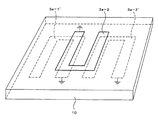
図3は発明の実施の形態2に係るインターディジタルフィルターの斜視図(わかりやすくするためにグランドを除く線路部分のみ示している)、図4(a)は平面図、図4(b)と(c)は平面図のX−X線で切断したときの断面図を示す。本フィルターはマイクロストリップ構造ないしストリップ線路構造で実現されるので、接地面が上下または下のみに設けられる。図4(b)はストリップ線路構造を、図4(c)はマイクロストリップ線路構造を示す。図中、符号10、10'は誘電体、11はグランド(接地面)、12はグランド11を接続するビアである。3a−1'、3a−2、3a−3'は結合線路(共振器)である(3a−1'は図1の3a−1に相当するが、図1のオープンスタブ6を備えない点で相違する。3a−3'は図1の3a−3に相当するが線路41に接続されていない点で相違する)。図3及び図4はインターディジタルフィルターの結合線路(共振器)の部分(特に入出力端を除く中間の部分)のみを示し、ノッチフィルターの構成部分の表示は省略している。ノッチフィルターの構成部分は図1と同様である。これらの図からわかるように、互い違いに平行に並べられる複数の共振器はそれぞれ誘電体基板10の一方の面に設けられ、互いに共振器の一部(3a−1'の一部と3a−2の一部、3a−2の一部と3a−3'の一部)が対向するように設けられている。
3 is a perspective view of the interdigital filter according to the second embodiment of the invention (only the line portion excluding the ground is shown for the sake of clarity), FIG. 4A is a plan view, and FIG. c) shows a cross-sectional view when cut along line XX in the plan view. Since this filter is realized by a microstrip structure or a stripline structure, the ground plane is provided only above and below or below. FIG. 4B shows a stripline structure, and FIG. 4C shows a microstripline structure. In the figure,
発明の実施の形態2によれば広帯域のフィルターを実現することができる。 According to the second embodiment of the invention, a broadband filter can be realized.
発明の実施の形態3.
ノッチフィルターの構成部分4を複数設けるようにしてもよい。複数ある場合、遮断する周波数が同じであれば、多段にするほど大きな減衰量が得られる。また別の遮断周波数に相当する線路を複数のノッチフィルターに持たせると、異なる周波数で遮断することができる。
A plurality of
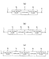
図5(a)は発明の実施の形態1に係るフィルターのブロック図であるが、これにさらにノッチフィルター4を追加してもよい。複数のノッチフィルターを設ける場合、図5(b)に示すようにノッチフィルター4aと4bは連続していてもよいし、図5(c)に示すようにインターディジタルフィルター3cをノッチフィルター4aと4bの間に設けてもよい。
FIG. 5A is a block diagram of a filter according to
ノッチフィルター4aと4bの遮断周波数を同じ(f1)にした場合、図5(b)と図5(c)いずれの場合でも周波数f1を大きく遮断することができる。一方のノッチフィルターの遮断周波数をf1とし、他方の遮断周波数をf2とした場合、図5(b)と図5(c)いずれの場合でもf1とf2の2つの周波数を遮断することができる。
When the cutoff frequencies of the
本発明は、以上の実施の形態に限定されることなく、特許請求の範囲に記載された発明の範囲内で、種々の変更が可能であり、それらも本発明の範囲内に包含されるものであることは言うまでもない。 The present invention is not limited to the above embodiments, and various modifications can be made within the scope of the invention described in the claims, and these are also included in the scope of the present invention. Needless to say.
1 入出力端
2 入出力端
3a インターディジタルフィルターの構成部分(第1インターディジタルフィルター)
3b インターディジタルフィルターの構成部分(第2インターディジタルフィルター)
3c インターディジタルフィルターの構成部分(第3インターディジタルフィルター)
4 ノッチフィルターの構成部分
41 使用周波数の1/2波長線路(第1線路)
5 遮断周波数の1/4波長線路(第2線路)
6 整合回路(オープンスタブ)
7 整合回路(オープンスタブ)
10、10' 誘電体
11 グランド(接地面)
12 ビア
1 Input /
3b Interdigital filter component (second interdigital filter)
3c Interdigital filter components (third interdigital filter)
4 Components of the
5 1/4 wavelength line of cutoff frequency (second line)
6 Matching circuit (open stub)
7 Matching circuit (open stub)
10, 10 '
12 Beer
Claims (9)
前記第2線路を、前記第1線路の中間点に設けたことを特徴とする請求項2記載のインターディジタルフィルター。 Sharing a part of the first line with at least a part of the plurality of resonators;
3. The interdigital filter according to claim 2, wherein the second line is provided at an intermediate point of the first line.
Priority Applications (1)
| Application Number | Priority Date | Filing Date | Title |
|---|---|---|---|
| JP2004079886A JP4209352B2 (en) | 2004-03-19 | 2004-03-19 | Interdigital filter |
Applications Claiming Priority (1)
| Application Number | Priority Date | Filing Date | Title |
|---|---|---|---|
| JP2004079886A JP4209352B2 (en) | 2004-03-19 | 2004-03-19 | Interdigital filter |
Publications (2)
| Publication Number | Publication Date |
|---|---|
| JP2005269321A JP2005269321A (en) | 2005-09-29 |
| JP4209352B2 true JP4209352B2 (en) | 2009-01-14 |
Family
ID=35093374
Family Applications (1)
| Application Number | Title | Priority Date | Filing Date |
|---|---|---|---|
| JP2004079886A Expired - Fee Related JP4209352B2 (en) | 2004-03-19 | 2004-03-19 | Interdigital filter |
Country Status (1)
| Country | Link |
|---|---|
| JP (1) | JP4209352B2 (en) |
Families Citing this family (4)
| Publication number | Priority date | Publication date | Assignee | Title |
|---|---|---|---|---|
| JP2006352277A (en) * | 2005-06-13 | 2006-12-28 | Tdk Corp | Wideband dielectric filter |
| CN101330161A (en) * | 2008-07-24 | 2008-12-24 | 上海杰盛无线通讯设备有限公司 | Minitype high-performance high-frequency microstrip interdigital filter |
| JP5575081B2 (en) | 2011-09-29 | 2014-08-20 | 株式会社東芝 | Resonant element, high frequency filter, wireless system |
| KR101598980B1 (en) * | 2014-05-07 | 2016-03-02 | 주식회사 이너트론 | Resonacne device and filter including the same |
-
2004
- 2004-03-19 JP JP2004079886A patent/JP4209352B2/en not_active Expired - Fee Related
Also Published As
| Publication number | Publication date |
|---|---|
| JP2005269321A (en) | 2005-09-29 |
Similar Documents
| Publication | Publication Date | Title |
|---|---|---|
| EP1990863B1 (en) | Dual band resonator and dual band filter | |
| EP0938153B1 (en) | Bandpass filter, duplexer, high-frequency module and communications device | |
| JP5060498B2 (en) | Dual-band bandpass resonator and dual-band bandpass filter | |
| US11158924B2 (en) | LTCC wide stopband filtering balun based on discriminating coupling | |
| JP3304724B2 (en) | Dual mode filter | |
| JP3531603B2 (en) | High frequency filter, filter device using the same, and electronic device using the same | |
| KR20090032512A (en) | A band-pass filter for ultrawide band | |
| JPH11186819A (en) | Band rejection filter and duplexer | |
| JP2002353775A (en) | Filter unit and duplexer comprising such filter unit | |
| JP4209352B2 (en) | Interdigital filter | |
| CN109193087A (en) | A kind of novel four function filter-divider of high-performance dual-passband | |
| JP2000357903A (en) | Planar filter | |
| JP2006101500A (en) | Filter | |
| US10673111B2 (en) | Filtering unit and filter | |
| JP5094524B2 (en) | High frequency coupled line and high frequency filter | |
| JP4501729B2 (en) | High frequency filter | |
| JP7360764B2 (en) | Bandpass filter and high frequency device equipped with the same | |
| CN111384535A (en) | Double-passband power division filter | |
| JPH07183710A (en) | Dielectric resonator and its input/output coupling circuit | |
| JPH11312902A (en) | Dielectric filter, transmission/reception equipment and communication equipment | |
| JP3750420B2 (en) | Planar filter, duplexer using the same, high frequency module using them, and communication device using the same | |
| JP2007243462A (en) | Band-pass filter and resonator | |
| JP2010081520A (en) | Structure of radio wave radiator with reflection layer | |
| JP5324497B2 (en) | Filter and satellite broadcast receiving apparatus using the same | |
| JP2006186828A (en) | Band pass filter |
Legal Events
| Date | Code | Title | Description |
|---|---|---|---|
| A621 | Written request for application examination |
Free format text: JAPANESE INTERMEDIATE CODE: A621 Effective date: 20061206 |
|
| A977 | Report on retrieval |
Free format text: JAPANESE INTERMEDIATE CODE: A971007 Effective date: 20071031 |
|
| A131 | Notification of reasons for refusal |
Free format text: JAPANESE INTERMEDIATE CODE: A131 Effective date: 20080818 |
|
| A521 | Written amendment |
Free format text: JAPANESE INTERMEDIATE CODE: A523 Effective date: 20080925 |
|
| TRDD | Decision of grant or rejection written | ||
| A01 | Written decision to grant a patent or to grant a registration (utility model) |
Free format text: JAPANESE INTERMEDIATE CODE: A01 Effective date: 20081020 |
|
| A01 | Written decision to grant a patent or to grant a registration (utility model) |
Free format text: JAPANESE INTERMEDIATE CODE: A01 |
|
| A61 | First payment of annual fees (during grant procedure) |
Free format text: JAPANESE INTERMEDIATE CODE: A61 Effective date: 20081022 |
|
| R150 | Certificate of patent or registration of utility model |
Free format text: JAPANESE INTERMEDIATE CODE: R150 |
|
| FPAY | Renewal fee payment (event date is renewal date of database) |
Free format text: PAYMENT UNTIL: 20111031 Year of fee payment: 3 |
|
| LAPS | Cancellation because of no payment of annual fees |