JP4208471B2 - Aqueous fluorescent ink, recording unit, ink cartridge, ink jet recording apparatus and ink jet recording method - Google Patents
Aqueous fluorescent ink, recording unit, ink cartridge, ink jet recording apparatus and ink jet recording method Download PDFInfo
- Publication number
- JP4208471B2 JP4208471B2 JP2002023677A JP2002023677A JP4208471B2 JP 4208471 B2 JP4208471 B2 JP 4208471B2 JP 2002023677 A JP2002023677 A JP 2002023677A JP 2002023677 A JP2002023677 A JP 2002023677A JP 4208471 B2 JP4208471 B2 JP 4208471B2
- Authority
- JP
- Japan
- Prior art keywords
- ink
- jet recording
- mass
- fluorescent
- recording
- Prior art date
- Legal status (The legal status is an assumption and is not a legal conclusion. Google has not performed a legal analysis and makes no representation as to the accuracy of the status listed.)
- Expired - Fee Related
Links
Images


Landscapes
- Ink Jet (AREA)
- Ink Jet Recording Methods And Recording Media Thereof (AREA)
- Inks, Pencil-Leads, Or Crayons (AREA)
Description
【0001】
【発明の属する技術分野】
本発明は、熱エネルギーによってインクを飛翔させて記録を行うインクジェット記録用の水性蛍光インク、このインクを用いたインクカートリッジ、記録ユニット、インクジェット記録装置及びインクジェット記録方法に関する。
【0002】
【従来の技術】
従来、ラインマーカーペンなどに蛍光性色材が使用されている。さらに最近では、堅牢性を向上させるために、蛍光顔料を使用したインクも登場してきている。例えば、特開平6−346013号公報や特開平5−239395号公報に有機蛍光顔料を使用した筆記具用蛍光顔料インクが開示されている。
【0003】
また、蛍光インクは上記のような筆記具としての用途の他に、電子透かしや料金別納郵便物の証印の印刷などにも用いられている。
【0004】
これらのプリントにインクジェットプリンタを使用することが特開平9−291246号公報に開示されている。この公報において、可溶性トナーを使用した耐水性インク組成物において、H.L.B.(HydrophileLipophileBalance)が8〜15の非イオン性界面活性剤を可溶化剤とすると開示している。
【0005】
電子透かしや郵便物の証印の印刷において、これらの印字物の蛍光強度をしきい値として利用する場合、安定した蛍光を発することが重要となる。しかしながら、上記先行技術によっては、安定した蛍光強度を得ることが出来ない場合があった。
【0006】
さらに、熱エネルギーによってインクを飛翔させて記録を行うインクジェット記録(バブルジェットと称す)においては、安定したインク吐出を行うために、インク吐出のために発泡を安定化しなければならないが、この点において上記のインクは未だ十分ではなかった。
【0007】
【発明が解決しようとする課題】
本発明の目的は、安定した蛍光を発生し、かつインクジェット記録、特にはバブルジェット記録に用いた場合に優れたインク吐出性を持つ水性蛍光インクを提供し、さらに、優れたインク吐出性ゆえに高品位な画質を安定して得ることができ、かつ画像堅牢性に優れた蛍光画像を得ることのできる記録ユニット、インクカートリッジ、インクジェット記録装置及びインクジェット記録方法を提供することにある。
【0008】
【課題を解決するための手段】
上記目的は以下の本発明によって達成される。
【0009】
すなわち、本発明は、水と、蛍光染料で着色された樹脂のエマルジョンと、25℃において固体である、非イオン性界面活性剤及びポリエチレングリコールと、を含有するインクジェット用の水性蛍光インクであって、該非イオン性界面活性剤及びポリエチレングリコールが、それぞれエチレンオキサイドユニットを25以上有し、該非イオン性界面活性剤及びポリエチレングリコールの含有量が、インク全質量に対して1質量%以上15質量%以下であることを特徴とするインクジェット用の水性蛍光インクである。
【0010】
このインクにおいて、前記着色された樹脂エマルジョンの含有量がインク全質量に対して1質量%以上40質量%以下であることが好ましい。
【0011】
前記樹脂のエマルジョンがアクリル樹脂のエマルジョンであることも好ましい。
【0012】
前記エチレンオキサイドユニットを有する水溶性化合物がポリエチレングリコールであることも好ましい。
【0013】
前記ポリエチレングリコールがエチレンオキサイドユニットを25以上有することも好ましい。
【0014】
前記ポリエチレングリコールをインク全質量に対して1〜10質量%含むことも好ましい。
【0015】
前記エチレンオキサイドユニットを有する水溶性化合物が非イオン性界面活性剤であることも好ましい。
【0016】
前記非イオン性界面活性剤がエチレンオキサイドユニットを25以上有することも好ましい。
【0017】
前記非イオン性界面活性剤をインク全質量に対して1〜5質量%含むことも好ましい。
【0018】
前記エチレンオキサイドユニットを有する化合物がポリエチレングリコールおよび非イオン性界面活性剤であることも好ましい。
【0019】
本発明は、上記の水性蛍光インクを収容しているインク収容部と、該インクを吐出させるためのインクジェットヘッドと、を具備していることを特徴とする記録ユニットを含む。
【0020】
本発明はまた、上記の水性蛍光インクを収容していることを特徴とするインクカートリッジも含む。
【0021】
本発明はさらに、上記のインクを収容しているインク収容部と、該インクを吐出させるためのインクジェットヘッドと、を具備していることを特徴とするインクジェット記録装置も含む。
【0022】
このインクジェット記録装置において、該インクジェットヘッドが、バブルジェットヘッドであることが好ましい。
【0023】
本発明はまた、上記の水性蛍光インクをインクジェット法で吐出させる工程を含むインクジェット記録方法も含む。
【0024】
【発明の実施の形態】
次に、好ましい実施の形態を挙げて、本発明をより詳細に説明する。
【0025】
〔着色樹脂エマルジョン〕
本発明に用いられる、蛍光染料で着色された樹脂のエマルジョンは、本発明にかかるインクにおける色材としての成分であり、例えば、アクリル樹脂系高分子化合物を蛍光性の染料で染色したもののエマルジョン(以下、「アクリル樹脂系高分子エマルジョン」と称す。)を挙げることができる。
【0026】
蛍光性の染料としては、蛍光性を有する染料であれば使用することが可能であり、例えば、C.I.アシッドブルー9、C.I.アシッドイエロー7、C.I.アシッドイエロー23、C.I.アシッドレッド52、C.I.アシッドレッド87、C.I.アシッドレッド92、C.I.アシッドブラック2等の酸性染料、C.I.ベーシックレッド1、C.I.ベーシックイエロー9、C.I.べ−シックイエロー44、C.I.べーシックバイオレット1、C.I.ベーシックバイオレット7、C.I.べ−シックバイオレット10、C.I.べ−シックバイオレット11、C.I.べ−シックブルー45等の塩基性染料が挙げられるがこれらに限定されない。
【0027】
アクリル樹脂系高分子エマルジョンを構成するモノマーとしては、アクリル酸やメタクリル酸の他、スチレンや塩化ビニル、アクリル酸およびメタクリル酸のエステル、マレイン酸、フマル酸やそのエステル、アクリロニトリルのようなビニルモノマー、他にウレタン系モノマー等が使用できるが、もちろんこれらに限定されるものではない。
【0028】
アクリル樹脂系高分子エマルジョンを製造する方法は、水などの溶媒中で一種又は2種以上の上記モノマーを重合あるいは共重合させる。重合あるいは共重合の方法は、特に限定されないが、乳化重合によって合成することが好ましい。
【0029】
アクリル樹脂系高分子エマルジョンを染料で染色する方法は、高分子化合物を染色できるものであれば特に制限なく適用可能であり、高分子化合物を合成する前段階で単量体に染料を反応させたり、重合中に染料を反応させたり、合成後に反応又は染着したりして得ることができる。
【0030】
着色樹脂中の染料の含有量は、染料の種類などによって異なるので一概に決定することは出来ないが、着色樹脂中の染料含有量が1質量%以上10質量%以下であることが好ましい。これより少ないと発色の点で十分とは言えない場合があり、あまり染料含有量が多いと耐水性が不十分になる場合や、染料高濃度による蛍光の濃度消光が起こる場合があるからである。
【0031】
〔25℃において固体である、エチレンオキサイドユニットを有する水溶性化合物〕
本発明のインクは、必須成分として、25℃において固体である、エチレンオキサイドユニット(−CH2CH2O−)を有する水溶性化合物を含有する。
【0032】
この化合物として、25℃において固体であるポリエチレングリコール及び非イオン性界面活性剤が用いられる。
【0033】
さらにより具体的には、エチレンオキサイドユニットを25以上有するポリエチレングリコール及び非イオン性界面活性剤が用いられる。
【0034】
ポリエチレングリコールでは、エチレンオキサイドユニットは200以下が好ましい。
【0035】
非イオン性界面活性剤では、エチレンオキサイドユニットは60以下が好ましい。
【0036】
また、上記のような非イオン性界面活性剤としては、ポリオキシエチレンラウリルエーテル、ポリオキシエチレンセチルエーテル、ポリオキシエチレンステアリルエーテル、ポリオキシエチレンオレイルエーテル、ポリオキシエチレンノニルフェニルエーテル、ポリオキシエチレンオクチルフェニルエーテル、ポリオキシエチレンステアリルアミン、ポリオキシエチレン等のエチレンオキサイド鎖が25以上のものを具体例として挙げることが出来るが、もちろん本発明はこれらに限定されるものではない。
【0037】
ところで、25℃において固体である、エチレンオキサイドユニットを有する水溶性化合物によって、本発明にかかるインクによるインクジェット記録物の蛍光が安定化する理由は明らかでないが、おそらく、これらの化合物の濃度消光(蛍光色材の発光を別な色材が吸収することによって蛍光強度が減少する現象)を抑制する効果を有している為ではないかと推測されるが、定かではない。
【0038】
さらに、これらの化合物によって、何故バブルジェット記録におけるインク吐出性が良好になるかは定かではないが、以下のように推測している。
【0039】
前記した、蛍光染料で着色された樹脂のエマルジョンを含有するインクは、エマルジョンが持つ疎水性部分によってインク吐出のための発泡が妨げられ、十分大きな泡に成長しないことが、吐出の不安定化を招いていると考えられる。なお、以下場合により、樹脂のエマルジョンすなわち樹脂が分散したエマルジョンを「樹脂エマルジョン」と称し、蛍光染料で着色された樹脂のエマルジョンを「着色樹脂エマルジョン」と称す。
【0040】
一方、25℃において液体であるエチレンオキサイドユニットが20程度のポリエチレングリコールは、水と自由に混合することが出来る。これに対して、25℃において固体であるポリエチレングリコールは有限の溶解度を持ち、少なくとも液体化合物より水への親和性を失っていると考えられる。そのため、これらの固体化合物はより疎水性な一面を持つ着色樹脂エマルジョンに配向し、エマルジョンの見かけの親水性を高める。これによって、着色樹脂エマルジョンによる発泡成長抑制が抑えられるため、安定したインク吐出が達成されると考えられる。
【0041】
以上の説明は非イオン性界面活性剤においても同様である。この場合、疎水ユニットを有する界面活性剤はより効果的に蛍光顔料エマルジョンに配向するため、ポリエチレングリコールよりはエチレンオキサイドのユニット数も少なく、かつ少量で同様の効果を達成できる。
【0042】
エチレンオキサイドユニットが少ない固体以外の界面活性剤の場合、化合物としての疎水性が強くなるため、十分な効果を発揮する濃度まで溶解させることが出来なかったり、着色樹脂エマルジョンの疎水性を緩和する作用が小さくなってしまうため、効果が得られない。
【0043】
〔インク〕
本発明にかかるインクジェット用の水性蛍光インクは、上記着色樹脂エマルジョンと、上記25℃において固体である、エチレンオキサイドユニットを有する化合物とを用い混合することによって着色樹脂(蛍光染料で着色された樹脂)がいわば顔料として水等の水性液媒体中に分散された溶液として製造することができる。
【0044】
これらの着色樹脂エマルジョンの含有量は、樹脂中の染料濃度によって決定されるが、インク中で好ましくは1〜40質量%、より好ましくは1〜20質量%の範囲で使用される。
【0045】
25℃において固体である、エチレンオキサイドユニットを有する化合物は、インク中に1質量%から15質量%含まれる。1質量%以上とすることにより本発明の効果が明瞭に発揮でき、15質量%以下とすることによりインクの粘度上昇などを抑えることができる。また15質量%を超えても、本発明の効果はあまり増大しない。
【0046】
インク中にポリエチレングリコールを1〜10質量%、あるいは非イオン性界面活性剤を1〜5質量%含むことが好ましい。それぞれ10あるいは5質量%を超えて含有させても、それ程効果が上がらないという点で不利となり、粘度の上昇によって若干インクジェットヘッドのノズル詰まりに不利になるからである。
【0047】
またこれらの化合物を併用することも好ましい。
【0048】
本発明にかかるインクに好適に用い得る水性液媒体は、水及び水溶性有機溶剤の混合溶媒であり、水としては種々のイオンを含有する一般の水ではなく、イオン交換水(脱イオン水)を使用するのが好ましい。
【0049】
水と混合して使用される水溶性有機溶剤としては、例えば、メチルアルコール、エチルアルコール、n−プロピルアルコール、イソプロピルアルコール、n−ブチルアルコール、sec−ブチルアルコール、tert−ブチルアルコール等の炭素数1〜4のアルキルアルコール類;ジメチルホルムアミド、ジメチルアセトアミド等のアミド類;アセトン、ジアセトンアルコール等のケトン又はケトアルコール類;テトラヒドロフラン、ジオキサン等のエーテル類;ポリエチレングリコール、ポリプロピレングリコール等のポリアルキレングリコール類;エチレングリコール、プロピレングリコール、ブチレングリコール、トリエチレングリコール、1,2,6−ヘキサントリオール、チオジグリコール、ヘキシレングリコール、ジエチレングリコール等のアルキレン基が2〜6個の炭素原子を含むアルキレングリコール類;グリセリン;エチレングリコールモノメチル(又はエチル)エーテル、ジエチレングリコールメチル(又はエチル)エーテル、トリエチレングリコールモノメチル(又はエチル)エーテル等の多価アルコールの低級アルキルエーテル類;N−メチル−2−ピロリドン、2−ピロリドン、1,3−ジメチル−2−イミダゾリジノン等が挙げられる。これらの多くの水溶性有機溶剤の中でもジエチレングリコール等の多価アルコール、トリエチレングリコールモノメチル(又はエチル)エーテル等の多価アルコールの低級アルキルエーテルが好ましい。
【0050】
上記した様な水溶性有機溶剤のインク中における含有量は、一般的にはインク全質量の3〜50質量%の範囲が好ましく、より好ましくは3〜30質量%の範囲とする。
【0051】
〔記録装置〕
次に、上記した本発明の水性蛍光インクを用いて記録を行うのに好適な本発明のインクジェット記録装置の一例を以下に説明するが、本発明のインクジェット記録装置は、インクを収容したインク収容部あるいはインクを収容したインク収容部を備えたインクカートリッジと、該インクを熱エネルギーの作用によりインク滴として吐出させるためのヘッド部を有する記録ユニットを備え、インクが上記本発明の水性蛍光顔料インクであること以外は、本発明による特段の制限は無い。
【0052】
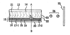
先ず、ヘッド構成の一例を図1及び図2に示す。図1は、インク流路に沿ったヘッド13の断面図であり、図2は図1のA−B線での切断面図である。ヘッド13はインクを通す流路(ノズル)14を有するガラス、セラミック、シリコン又はプラスチック板等と発熱素子基板15とを接着して得られる。発熱素子基板15は酸化シリコン、窒化シリコン、炭化シリコン等で形成される保護層16、アルミニウム、金、アルミニウム−銅合金等で形成される電極17−1及び17−2、HfB2、TaN、TaAl等の高融点材料から形成される発熱抵抗体層18、熱酸化シリコン、酸化アルミニウム等で形成される蓄熱層19、シリコン、アルミニウム、窒化アルミニウム等の放熱性のよい材料で形成される基板20よりなっている。
【0053】
上記ヘッド13の電極17−1及び17−2にパルス状の電気信号が印加されると、発熱素子基板15のnで示される領域が急速に発熱し、この表面に接しているインク21に気泡が発生し、その圧力でメニスカス23が突出し、インク21がヘッドのノズル14を通して吐出し、吐出オリフィス22よりインク小滴24となり、被記録材25に向かって飛翔する。図3には、図1に示したヘッドを多数並べたマルチヘッドの一例の外観図を示す。このマルチヘッドは、マルチノズル26を有するガラス板27と、図1に説明したものと同じような発熱素子基板28を接着して作られている。
【0054】
図4に、このヘッドを組み込んだインクジェット記録装置の一例を示す。図4において、61はワイピング部材としてのブレードであり、その一端はブレード保持部材によって保持固定されており、カンチレバーの形態をなす。ブレード61は記録ヘッド65による記録領域に隣接した位置に配置され、又、本例の場合、記録ヘッド65の移動経路中に突出した形態で保持される。
【0055】
62は記録ヘッド65の突出口面のキャップであり、ブレード61に隣接するホームポジションに配置され、記録ヘッド65の移動方向と垂直な方向に移動して、インク吐出口面と当接し、キャッピングを行う構成を備える。更に、63はブレード61に隣接して設けられるインク吸収体であり、ブレード61と同様、記録ヘッド65の移動経路中に突出した形態で保持される。上記ブレード61、キャップ62及びインク吸収体63によって吐出回復部64が構成され、ブレード61及びインク吸収体63によって吐出口面に水分、塵挨等の除去が行われる。
【0056】
65は、吐出エネルギー発生手段を有し、吐出口を配した吐出ロ面に対向する被記録材にインクを吐出して記録を行う記録ヘッド、66は記録ヘッド65を搭載して記録ヘッド65の移動を行うためのキャリッジである。キャリッジ66はガイド軸67と摺動可能に系合し、キャリッジ66の一部はモーター68によって駆動されるベルト69と接続(不図示)している。
【0057】
これによりキャリッジ66はガイド軸67に沿った移動が可能となり、記録ヘッド65による記録領域及びその隣接した領域の移動が可能となる。
【0058】
51は被記録材を挿入するための紙給部、52は不図示のモーターにより駆動される紙送りローラーである。これらの構成により記録ヘッド65の吐出口面と対向する位置へ被記録材が給紙され、記録が進行するにつれて排紙ローラー53を配した排紙部へ排紙される。以上の構成において記録ヘッド65が記録終了してホームポジションへ戻る際、吐出回復部64のキヤップ62は記録ヘッド65の移動経路から退避しているが、ブレード61は移動経路中に突出している。その結果、記録ヘッド65の吐出口がワイピングされる。
【0059】
尚、キャップ62が記録ヘッド65の吐出面に当接してキャッピングを行う場合、キャップ62は記録ヘッドの移動経路中に突出するように移動する。記録ヘッド65がホームポジションから記録開始位置へ移動する場合、キャップ62及びブレード61は上記したワイピングの時の位置と同一の位置にある。この結果、この移動においても記録ヘッド65の吐出口面はワイビングされる。上述の記録ヘッドのホームポジションへの移動は、記録終了時や吐出回復時ばかりでなく、記録ヘッドが記録のために記録領域を移動する間に所定の間隔で記録領域に隣接したホームポジションヘ移動し、この移動に伴って上記ワイピングが行われる。
【0060】
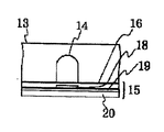
図5は、図4中の記録ヘッドにインク供給部材、例えば、チューブを介して供給されるインクを収容したインクカートリッジの一例を示す図である(図4中不図示)。45はインクカートリッジである。ここで40は供給用インクを収納したインク収容部、例えば、インク袋であり、その先端にはゴム製の栓42が設けられている。この栓42に針(不図示)を挿入することにより、インク袋40中のインクをヘッドに供給可能にする。44は廃インクを受容するインク吸収体である。インク収容部としてはインクとの接液面がポリオレフイン、特にポリエチレンで形成されているものが好ましい。
【0061】
本発明のインクカートリッジとしては、インクを収容したインク収容部を備えたものであれば、収容するインクが本発明の水性蛍光顔料インクである点を除いて特に制限はない。
【0062】
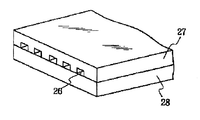
本発明においては、上述のようにヘッドとインクカートリッジとが別体となったものに限らず、図6に示すようなそれらが一体になった記録ユニットも好適に用いられる。図6において、70は記録ユニットであり、この中にはインクを収容したインク収容部、例えば、インク吸収体が収納されており、かかるインク吸収体中のインクが複数オリフィスを有するヘッド部71からインク滴として吐出される構成になっている。インク吸収体の材料としてはポリウレタンを用いることが本発明にとって好ましい。又、インク吸収体を用いず、インク収容部が内部にバネ等を仕込んだインク袋であるような構造でもよい。72はカートリッジ内部を大気に連通させるための大気連通口である。この記録ユニット70は図4に示す記録ヘッド65に換えて用いられるものであって、キャリッジ66に対して着脱自在になっている。
【0063】
本発明の記録ユニットとしては、インクを収容したインク収容部と、該インクを熱エネルギーの作用によりインク滴として吐出させるためのヘッド部とを備えたものであれば、収容するインクが本発明の水性蛍光顔料インクである点を除いては特に制限はない。
【0064】
【実施例】
次に、実施例及び比較例を挙げて本発明をより具体的に説明するが、本発明は下記実施例により限定されるものではない。尚、文中「部」及び「%」とあるのは、特に断りのない限り質量基準である。
【0065】
〔参考例1〕
1)水性蛍光性着色樹脂エマルジョン
・蛍光性の酸性染料で着色されたアクリル樹脂エマルジョン
(商品名:SF−5017;シンロイヒ社製):20部
2)非イオン性界面活性剤
ポリオキシエチレンセチルエーテル(エチレンオキサイド40ユニット)、25℃固体)
(商品名:BC−40TX;日光ケミカルズ社製):2.0部
3)他の成分
・アセチレングリコールのエチレンオキサイド付加物
(商品名:アセチレノールEH:川研フアインケミカル社製):0.5部
・ジエチレングリコール:15部
・トリメチロールプロパン:5部
・純水:57.5部
以上の成分を混合し、充分攪拌して溶解した後、ポアサイズ2.5μmのミクロフイルター(富士フィルム製)にて加圧濾過しインクを調製した。
【0066】
上記のインクを用いて、記録信号に応じた熱エネルギーをインクに付与することによりインクを吐出させるオンデマンド型マルチバブルジェットヘッドを有するインクジェット記録装置BJC−430J(キヤノン製)を用いてプリント評価を行った。
【0067】
評価に用いた用紙はキヤノン製PPC用紙、PB−ペーパーである。
【0068】
その結果、安定したプリントを得ることが出来た。また、印字物は完全な耐水性を有していた。印字物を蛍光光度計で測定したところ、赤色蛍光が観測され、紙のロットによる蛍光強度の変動も観測されなかった。
【0069】
〔参考例2〕
1)水性蛍光性着色樹脂エマルジョン
・蛍光性酸性染料で着色されたアクリル樹脂エマルジョン
(商品名:LUMIKOL NKW−3207C;日本蛍光社製):15部
2)ポリエチレングリコール
・ポリエチレングリコール(分子量4000、エチレンオキサイド平均約90ユニット、25℃固体):7.0部
3)他の成分
・ジエチレングリコール:15部
・トリメチロールプロパン:5部
・アセチレングリコールのエチレンオキサイド付加物
(商品名:アセチレノールEH;川研ファインケミカル社製):0.5部
・純水:57.5部
以上の成分を用いたこと以外は参考例1と同様にして、プリント評価したところ、良好な結果を得た。また、参考例2では赤色蛍光が観測され、参考例1と同様に蛍光強度も安定していた。
【0070】
〔実施例1〕
1)水性蛍光性着色樹脂エマルジョン
蛍光性酸性染料で着色されたアクリル樹脂エマルジョン
(商品名:SF−5014;シンロイヒ社製):30部
2)ポリエチレングリコールおよび非イオン性界面活性剤
・ポリエチレングリコール
(分子量1000、エチレンオキサイド平均25ユニット、25℃固体):5.0部
・ポリオキシエチレンオレイルエーテル(エチレンオキサイド50ユニット)
(商品名:B0−50;日光ケミカルズ社製):2.0部
3)他の成分
・ジエチレングリコール:15部
・トリメチロールプロパン:5部
・アセチレングリコールのエチレンオキサイド付加物
(商品名:アセチレノールEH;川研ファインケミカル社製):0.5部
・純水:42.5部
以上の成分を用いたこと以外は、参考例1と同様にプリント評価したところ、良好な結果を得た。黄緑蛍光が観測され、参考例1と同様に蛍光強度も安定していた。実施例1ではポリエチレングリコールと界面活性剤の併用によって高濃度のエマルジョン濃度でも安定して使用することが出来た。
【0071】
〔比較例1〕
1)水性蛍光性樹脂エマルジョン
・蛍光性酸性染料で着色されたアクリル樹脂エマルジョン
(商品名:SF−5017;シンロイヒ社製):20部
2)他の成分
・ジエチレングリコール:15部
・トリメチロールプロパン:5部
・アセチレングリコールのエチレンオキサイド付加物
(商品名:アセチレノールEH;川研ファインケミカル社製):0.5部
・純水:59.5部
参考例1と同様にプリント評価したところ、プリントヘッドからインクが吐出せず、全く評価できなかった。
【0072】
〔比較例2〕
1)水性蛍光着色樹脂エマルジョン
蛍光性酸性染料で着色された樹脂エマルジョン
(商品名:SF−5017;シンロイヒ社製):20部
2)非イオン性界面活性剤
・ポリオキシエチレンセチルエーテル(エチレンオキサイド10ユニット)、25℃液体〜ペースト状)
(商品名:BC−10TX;日光ケミカルズ社製):2.0部
3)他の成分
・ジエチレングリコール:15部
・トリメチロールプロパン:5部
・アセチレングリコールのエチレンオキサイド付加物
(商品名:アセチレノールEH;川研ファインケミカル社製):0.5部
・純水:57.5部
参考例1と同様にプリント評価したところ、かすれた印字となり、評価が困難だった。
【0073】
印字が良好な部分を選んで蛍光強度を測定したところ、目視では印字濃度等は問題ないように見えたが、蛍光強度はまちまちで、電子透かし等に使用できるレベルではなかった。
【0074】
〔比較例3〕
1)水性蛍光性着色樹脂エマルジョン
・蛍光性酸性染料で着色されたアクリル樹脂エマルジョン
(商品名:SF−5014;シンロイヒ社製):20部
2)ポリエチレングリコール
ポリエチレングリコール(分子量200、25℃液体):5.0部
3)他の成分
・ジエチレングリコール:15部
・トリメチロールプロパン:5部
・アセチレングリコールのエチレンオキサイド付加物
(商品名:アセチレノールEH;川研ファインケミカル社製):0.5部
・純水:54.5部
参考例1と同様にプリント評価したところ、プリントヘッドからインクが吐出せず、評価できなかった。
【0075】
【発明の効果】
以上説明したように、本発明によれば、バブルジェット記録に用いた場合に優れたインク吐出性と画像堅牢性に優れたインクジェット用の水性蛍光性のインクを得ることが出来る。さらに、優れたインク吐出性のために高品位な画質を安定して得ることができ、かつ画像堅牢性に優れた蛍光画像を得ることのできるインクカートリッジ、記録ユニットおよびインクジェット記録装置および方法が提供された。
【図面の簡単な説明】
【図1】インクジェット記録装置のヘッドの一例を示す縦断面図である。
【図2】インクジェット記録装置のヘッドの一例を示す横断面図である。
【図3】図1に示したヘッドをマルチ化したヘッドの外観斜視図である。
【図4】インクジェット記録装置の一例を示す概略斜視図である。
【図5】インクカートリッジの一例を示す縦断面図である。
【図6】記録ユニットの一例を示す斜視図である。
【符号の説明】
13:ヘッド
14:ノズル
15:発熱素子基板
16:保護層
17−1、17−2:電極
18:発熱抵抗体層
19:蓄熱層
20:基板
21:インク
22:吐出オリフィス(微細孔)
23:メニスカス
24:インク小滴
25:被記録材
26:マルチノズル
27:ガラス板
28:発熱素子基板
40:インク袋
42:栓
44:インク吸収体
45:インクカートリッジ
51:給紙部
52:紙送りローラー
53:排紙ローラー
61:ブレード
62:キャップ
63:インク吸収体
64:吐出回復部
65:記録ヘッド
66:キャリッジ
67:ガイド軸
68:モーター
69:ベルト
70:記録ユニット
71:ヘッド部
72:大気連通口[0001]
BACKGROUND OF THE INVENTION
The present invention relates to a water-based fluorescent ink for ink-jet recording that performs recording by flying ink with thermal energy, an ink cartridge, a recording unit, an ink-jet recording apparatus, and an ink-jet recording method using the ink.
[0002]
[Prior art]
Conventionally, a fluorescent color material is used for a line marker pen or the like. More recently, inks using fluorescent pigments have been introduced to improve fastness. For example, JP-A-6-346013 and JP-A-5-239395 disclose fluorescent pigment inks for writing instruments using organic fluorescent pigments.
[0003]
In addition to the use as a writing instrument as described above, the fluorescent ink is also used for printing an electronic watermark or indicia of a postage by postage.
[0004]
Japanese Unexamined Patent Publication No. 9-291246 discloses the use of an ink jet printer for these prints. In this publication, in a water-resistant ink composition using a soluble toner, H.P. L. B. (Hydrophyl Lipophil Balance) discloses 8-15 nonionic surfactants as solubilizers.
[0005]
In the printing of digital watermarks and postal indicia, when using the fluorescence intensity of these printed matter as a threshold value, it is important to emit stable fluorescence. However, depending on the above prior art, stable fluorescence intensity may not be obtained.
[0006]
Furthermore, in ink jet recording (referred to as bubble jet) in which recording is performed by flying ink with thermal energy, in order to perform stable ink ejection, foam must be stabilized for ink ejection. The above ink was still not sufficient.
[0007]
[Problems to be solved by the invention]
An object of the present invention is to provide a water-based fluorescent ink that generates stable fluorescence and has excellent ink discharge properties when used in ink jet recording, particularly bubble jet recording, and has high ink discharge properties. It is an object of the present invention to provide a recording unit, an ink cartridge, an ink jet recording apparatus, and an ink jet recording method capable of stably obtaining a high quality image and obtaining a fluorescent image excellent in image fastness.
[0008]
[Means for Solving the Problems]
The above object is achieved by the present invention described below.
[0009]
That is, the present inventionwater and,A resin emulsion colored with a fluorescent dye and a solid at 25 ° C.An aqueous fluorescent ink for ink jet containing a nonionic surfactant and polyethylene glycol,The nonionic surfactant and polyethylene glycol each have 25 or more ethylene oxide units, and the content of the nonionic surfactant and polyethylene glycol is from 1% by mass to 15% by mass with respect to the total mass of the ink. There is a water-based fluorescent ink for ink-jets.
[0010]
In this ink,The content of the colored resin emulsion is 1% by mass or more and 40% by mass or less based on the total mass of the ink.It is preferable that
[0011]
The resin emulsion is an acrylic resin emulsion.It is also preferable.
[0012]
It is also preferable that the water-soluble compound having the ethylene oxide unit is polyethylene glycol.
[0013]
It is also preferable that the polyethylene glycol has 25 or more ethylene oxide units.
[0014]
It is also preferable to contain 1 to 10% by mass of the polyethylene glycol with respect to the total mass of the ink.
[0015]
It is also preferable that the water-soluble compound having the ethylene oxide unit is a nonionic surfactant.
[0016]
It is also preferred that the nonionic surfactant has 25 or more ethylene oxide units.
[0017]
It is also preferable that the nonionic surfactant is contained in an amount of 1 to 5% by mass based on the total mass of the ink.
[0018]
It is also preferred that the compound having an ethylene oxide unit is polyethylene glycol and a nonionic surfactant.
[0019]
The present invention includes a recording unit including an ink storage unit that stores the above-described water-based fluorescent ink, and an ink jet head that discharges the ink.
[0020]
The present invention also includes an ink cartridge containing the above-described aqueous fluorescent ink.
[0021]
The present invention further includes an ink jet recording apparatus comprising an ink containing portion containing the above ink and an ink jet head for discharging the ink.
[0022]
In this ink jet recording apparatus, the ink jet head is preferably a bubble jet head.
[0023]
The present invention also includes an ink jet recording method including a step of discharging the above-described aqueous fluorescent ink by an ink jet method.
[0024]
DETAILED DESCRIPTION OF THE INVENTION
Next, the present invention will be described in more detail with reference to preferred embodiments.
[0025]
[Colored resin emulsion]
The emulsion of a resin colored with a fluorescent dye used in the present invention is a component as a coloring material in the ink according to the present invention. For example, an emulsion of an acrylic resin polymer compound dyed with a fluorescent dye ( (Hereinafter referred to as “acrylic polymer emulsion”).
[0026]
As the fluorescent dye, any dye having fluorescence can be used. I. Acid Blue 9, C.I. I. Acid Yellow 7, C.I. I. Acid Yellow 23, C.I. I. Acid Red 52, C.I. I. Acid Red 87, C.I. I. Acid Red 92, C.I. I. Acid dyes such as Acid Black 2, C.I. I. Basic Red 1, C.I. I. Basic Yellow 9, C.I. I.
[0027]
As monomers constituting the acrylic resin polymer emulsion, in addition to acrylic acid and methacrylic acid, styrene and vinyl chloride, esters of acrylic acid and methacrylic acid, maleic acid, fumaric acid and esters thereof, vinyl monomers such as acrylonitrile, In addition, urethane-based monomers can be used, but of course not limited thereto.
[0028]
In the method for producing an acrylic resin polymer emulsion, one or two or more of the above monomers are polymerized or copolymerized in a solvent such as water. The method of polymerization or copolymerization is not particularly limited, but is preferably synthesized by emulsion polymerization.
[0029]
The method of dyeing an acrylic resin polymer emulsion with a dye can be applied without particular limitation as long as it can dye a polymer compound. For example, a dye can be reacted with a monomer in the previous step of synthesizing the polymer compound. It can be obtained by reacting a dye during polymerization, or reacting or dyeing after synthesis.
[0030]
Since the content of the dye in the colored resin varies depending on the type of the dye and the like, it cannot be determined unconditionally, but the dye content in the colored resin is preferably 1% by mass or more and 10% by mass or less. If it is less than this, it may not be sufficient in terms of color development, and if the dye content is too high, water resistance may be insufficient, or fluorescence quenching may occur due to high dye concentration. .
[0031]
[Water-soluble compound having an ethylene oxide unit that is solid at 25 ° C.]
The ink of the present invention has, as an essential component, an ethylene oxide unit (—CH that is solid at 25 ° C.2CH2A water-soluble compound having O-).
[0032]
This compoundAsSolid at 25 ° CIsPolyethylene glycolas well asNonionic surfactantIs used.
[0033]
Even more specifically, polyethylene glycol having 25 or more ethylene oxide units.as well asNonionic surfactantIs used.
[0034]
In polyethylene glycol, the ethylene oxide unit is preferably 200 or less.
[0035]
In the nonionic surfactant, the ethylene oxide unit is preferably 60 or less.
[0036]
Examples of the nonionic surfactant as described above include polyoxyethylene lauryl ether, polyoxyethylene cetyl ether, polyoxyethylene stearyl ether, polyoxyethylene oleyl ether, polyoxyethylene nonylphenyl ether, polyoxyethylene octyl. Specific examples include those having 25 or more ethylene oxide chains such as phenyl ether, polyoxyethylene stearylamine, and polyoxyethylene, but the present invention is not limited thereto.
[0037]
By the way, it is not clear why the water-soluble compound having an ethylene oxide unit, which is solid at 25 ° C., stabilizes the fluorescence of the ink jet recording by the ink according to the present invention. It is presumed that this is because it has the effect of suppressing the phenomenon in which the fluorescence intensity decreases due to the absorption of the light emission of the color material by another color material, but it is not certain.
[0038]
Furthermore, although it is not certain why these compounds improve the ink discharge performance in bubble jet recording, it is presumed as follows.
[0039]
Ink containing an emulsion of a resin colored with a fluorescent dye as described above is prevented from foaming for ink ejection due to the hydrophobic portion of the emulsion and does not grow into a sufficiently large bubble. It is thought to have been invited. In the following cases, an emulsion of a resin, that is, an emulsion in which a resin is dispersed is referred to as a “resin emulsion”, and an emulsion of a resin colored with a fluorescent dye is referred to as a “colored resin emulsion”.
[0040]
On the other hand, polyethylene glycol having about 20 ethylene oxide units that are liquid at 25 ° C. can be freely mixed with water. On the other hand, polyethylene glycol which is solid at 25 ° C. has a finite solubility and is considered to have lost its affinity for water at least as compared with a liquid compound. Therefore, these solid compounds are oriented to a colored resin emulsion having a more hydrophobic surface, and increase the apparent hydrophilicity of the emulsion. As a result, the suppression of foaming growth by the colored resin emulsion can be suppressed, and it is considered that stable ink ejection is achieved.
[0041]
The above description is the same for the nonionic surfactant. In this case, since the surfactant having hydrophobic units is more effectively oriented into the fluorescent pigment emulsion, the number of units of ethylene oxide is smaller than that of polyethylene glycol, and the same effect can be achieved with a small amount.
[0042]
In the case of surfactants other than solids with a small amount of ethylene oxide units, the hydrophobicity of the compound becomes strong, so it cannot be dissolved to a concentration that exhibits sufficient effects, or the hydrophobicity of the colored resin emulsion is reduced The effect is not obtained because of the decrease in size.
[0043]
〔ink〕
The aqueous fluorescent ink for ink jet according to the present invention is a colored resin (resin colored with a fluorescent dye) by mixing the colored resin emulsion and the compound having an ethylene oxide unit that is solid at 25 ° C. In other words, the pigment can be produced as a solution dispersed in an aqueous liquid medium such as water.
[0044]
The content of these colored resin emulsions is determined by the dye concentration in the resin, but is preferably 1 to 40% by mass, more preferably 1 to 20% by mass in the ink.
[0045]
The compound having an ethylene oxide unit that is solid at 25 ° C. is contained in the ink in an amount of 1% by mass to 15% by mass.TheBy setting the content to 1% by mass or more, the effect of the present invention can be clearly exhibited, and by setting the content to 15% by mass or less, an increase in the viscosity of the ink can be suppressed. Moreover, even if it exceeds 15 mass%, the effect of this invention does not increase so much.
[0046]
The ink preferably contains 1 to 10% by mass of polyethylene glycol or 1 to 5% by mass of nonionic surfactant. Even if each content exceeds 10 or 5% by mass, it is disadvantageous in that the effect is not so much improved, and the increase in viscosity is somewhat disadvantageous for nozzle clogging of the inkjet head.
[0047]
It is also preferable to use these compounds in combination.
[0048]
The aqueous liquid medium that can be suitably used in the ink according to the present invention is a mixed solvent of water and a water-soluble organic solvent, and the water is not general water containing various ions but ion-exchanged water (deionized water). Is preferably used.
[0049]
Examples of the water-soluble organic solvent used by mixing with water include carbon atoms of 1 such as methyl alcohol, ethyl alcohol, n-propyl alcohol, isopropyl alcohol, n-butyl alcohol, sec-butyl alcohol, tert-butyl alcohol, and the like. Alkyl alcohols of -4; amides such as dimethylformamide and dimethylacetamide; ketones or ketoalcohols such as acetone and diacetone alcohol; ethers such as tetrahydrofuran and dioxane; polyalkylene glycols such as polyethylene glycol and polypropylene glycol; Ethylene glycol, propylene glycol, butylene glycol, triethylene glycol, 1,2,6-hexanetriol, thiodiglycol, hexylene glycol, diethylene glycol Alkylene glycols having 2 to 6 carbon atoms, such as coal; glycerin; ethylene glycol monomethyl (or ethyl) ether, diethylene glycol methyl (or ethyl) ether, triethylene glycol monomethyl (or ethyl) ether, etc. Lower alkyl ethers of monohydric alcohols; N-methyl-2-pyrrolidone, 2-pyrrolidone, 1,3-dimethyl-2-imidazolidinone and the like. Of these many water-soluble organic solvents, polyhydric alcohols such as diethylene glycol and lower alkyl ethers of polyhydric alcohols such as triethylene glycol monomethyl (or ethyl) ether are preferred.
[0050]
The content of the water-soluble organic solvent in the ink as described above is generally preferably in the range of 3 to 50% by mass, more preferably in the range of 3 to 30% by mass with respect to the total mass of the ink.
[0051]
[Recording device]
Next, an example of the ink jet recording apparatus of the present invention suitable for recording using the above-described aqueous fluorescent ink of the present invention will be described below. The ink jet recording apparatus of the present invention is an ink container containing ink. Or a recording unit having a head unit for ejecting the ink as ink droplets by the action of thermal energy, wherein the ink is the aqueous fluorescent pigment ink of the present invention. There is no special limitation by this invention except being.
[0052]
First, an example of the head configuration is shown in FIGS. FIG. 1 is a cross-sectional view of the
[0053]
When a pulsed electric signal is applied to the electrodes 17-1 and 17-2 of the
[0054]
FIG. 4 shows an example of an ink jet recording apparatus incorporating this head. In FIG. 4, reference numeral 61 denotes a blade as a wiping member, one end of which is held and fixed by a blade holding member, and forms a cantilever. The blade 61 is disposed at a position adjacent to the recording area by the recording head 65, and in this example, is held in a form protruding in the moving path of the recording head 65.
[0055]
Reference numeral 62 denotes a cap on the projection port surface of the recording head 65, which is disposed at a home position adjacent to the blade 61, moves in a direction perpendicular to the moving direction of the recording head 65, contacts the ink ejection port surface, and performs capping. The structure to perform is provided. Further,
[0056]
Reference numeral 65 denotes a recording head that has discharge energy generating means and performs recording by discharging ink onto a recording material facing the discharge roll surface provided with the discharge ports. It is a carriage for moving. The carriage 66 is slidably engaged with the guide shaft 67, and a part of the carriage 66 is connected to a belt 69 (not shown) driven by a motor 68.
[0057]
As a result, the carriage 66 can move along the guide shaft 67, and the recording area and its adjacent area can be moved by the recording head 65.
[0058]
51 is a paper feeding unit for inserting a recording material, and 52 is a paper feed roller driven by a motor (not shown). With these configurations, the recording material is fed to a position facing the discharge port surface of the recording head 65, and is discharged to a paper discharge portion provided with a paper discharge roller 53 as recording progresses. In the above configuration, when the recording head 65 finishes recording and returns to the home position, the cap 62 of the ejection recovery unit 64 is retracted from the moving path of the recording head 65, but the blade 61 protrudes into the moving path. As a result, the ejection port of the recording head 65 is wiped.
[0059]
When the cap 62 is in contact with the ejection surface of the recording head 65 to perform capping, the cap 62 moves so as to protrude into the moving path of the recording head. When the recording head 65 moves from the home position to the recording start position, the cap 62 and the blade 61 are at the same position as that at the time of wiping described above. As a result, the ejection port surface of the recording head 65 is also wibbed during this movement. The above-mentioned movement of the recording head to the home position is not only at the end of recording or at the time of ejection recovery, but also to the home position adjacent to the recording area at a predetermined interval while the recording head moves the recording area for recording. Then, the wiping is performed with this movement.
[0060]
FIG. 5 is a view showing an example of an ink cartridge (not shown in FIG. 4) in which the recording head in FIG. 4 accommodates ink supplied via an ink supply member, for example, a tube. 45 is an ink cartridge. Here,
[0061]
The ink cartridge of the present invention is not particularly limited as long as it has an ink storage portion that stores ink, except that the ink to be stored is the aqueous fluorescent pigment ink of the present invention.
[0062]
In the present invention, not only the head and the ink cartridge are separated as described above, but also a recording unit in which they are integrated as shown in FIG. 6 is preferably used. In FIG. 6,
[0063]
As the recording unit of the present invention, as long as the recording unit includes an ink storage unit that stores ink and a head unit that discharges the ink as ink droplets by the action of thermal energy, the stored ink is the same as that of the present invention. There is no particular limitation except that it is an aqueous fluorescent pigment ink.
[0064]
【Example】
EXAMPLES Next, although an Example and a comparative example are given and this invention is demonstrated more concretely, this invention is not limited by the following Example. In the text, “parts” and “%” are based on mass unless otherwise specified.
[0065]
[referenceExample 1)
1) Aqueous fluorescent colored resin emulsion
・ Acrylic resin emulsion colored with fluorescent acid dye
(Product name: SF-5017; manufactured by Sinloihi): 20 parts
2) Nonionic surfactant
Polyoxyethylene cetyl ether (
(Product name: BC-40TX; manufactured by Nikko Chemicals): 2.0 parts
3) Other ingredients
・ Ethylene oxide adduct of acetylene glycol
(Brand name: Acetylenol EH: Kawaken Fine Chemical Co., Ltd.): 0.5 parts
・ Diethylene glycol: 15 parts
・ Trimethylolpropane: 5 parts
・ Pure water: 57.5 parts
The above components were mixed, sufficiently stirred and dissolved, and then pressure filtered with a microfilter (manufactured by Fuji Film) having a pore size of 2.5 μm to prepare an ink.
[0066]
Using the above-described ink, print evaluation is performed using an inkjet recording apparatus BJC-430J (manufactured by Canon) having an on-demand type multi-bubble jet head that discharges ink by applying thermal energy corresponding to a recording signal to the ink. went.
[0067]
The paper used for the evaluation is Canon PPC paper, PB-paper.
[0068]
As a result, a stable print could be obtained. Further, the printed matter had complete water resistance. When the printed matter was measured with a fluorometer, red fluorescence was observed, and no variation in fluorescence intensity due to paper lots was observed.
[0069]
[referenceExample 2)
1) Aqueous fluorescent colored resin emulsion
・ Acrylic resin emulsion colored with fluorescent acid dye
(Product name: LUMIKOL NKW-3207C; manufactured by Nippon Fluorescence): 15 parts
2) Polyethylene glycol
Polyethylene glycol (molecular weight 4000, ethylene oxide average about 90 units, 25 ° C. solid): 7.0 parts
3) Other ingredients
・ Diethylene glycol: 15 parts
・ Trimethylolpropane: 5 parts
・ Ethylene oxide adduct of acetylene glycol
(Product name: Acetylenol EH; Kawaken Fine Chemical Co., Ltd.): 0.5 parts
・ Pure water: 57.5 parts
Except for using the above ingredientsreferenceWhen print evaluation was performed in the same manner as in Example 1, good results were obtained. Also,referenceIn Example 2, red fluorescence is observed,referenceAs in Example 1, the fluorescence intensity was stable.
[0070]
〔Example1]
1) Aqueous fluorescent colored resin emulsion
Acrylic resin emulsion colored with fluorescent acid dye
(Product name: SF-5014; manufactured by Sinloihi): 30 parts
2) Polyethylene glycol and nonionic surfactant
・ Polyethylene glycol
(Molecular weight 1000, ethylene oxide average 25 units, 25 ° C. solid): 5.0 parts
・ Polyoxyethylene oleyl ether (ethylene oxide 50 units)
(Product name: B0-50; manufactured by Nikko Chemicals): 2.0 parts
3) Other ingredients
・ Diethylene glycol: 15 parts
・ Trimethylolpropane: 5 parts
・ Ethylene oxide adduct of acetylene glycol
(Product name: Acetylenol EH; Kawaken Fine Chemical Co., Ltd.): 0.5 parts
・ Pure water: 42.5 parts
Except for using the above ingredients,referenceWhen print evaluation was performed in the same manner as in Example 1, good results were obtained. Yellow-green fluorescence is observed,referenceAs in Example 1, the fluorescence intensity was stable. Example1Therefore, the combined use of polyethylene glycol and surfactant enabled stable use even at high emulsion concentrations.
[0071]
[Comparative Example 1]
1) Aqueous fluorescent resin emulsion
・ Acrylic resin emulsion colored with fluorescent acid dye
(Product name: SF-5017; manufactured by Sinloihi): 20 parts
2) Other ingredients
・ Diethylene glycol: 15 parts
・ Trimethylolpropane: 5 parts
・ Ethylene oxide adduct of acetylene glycol
(Product name: Acetylenol EH; Kawaken Fine Chemical Co., Ltd.): 0.5 parts
・ Pure water: 59.5 parts
referenceWhen printing was evaluated in the same manner as in Example 1, no ink was ejected from the print head, and no evaluation was possible.
[0072]
[Comparative Example 2]
1) Aqueous fluorescent colored resin emulsion
Resin emulsion colored with fluorescent acid dyes
(Product name: SF-5017; manufactured by Sinloihi): 20 parts
2) Nonionic surfactant
・ Polyoxyethylene cetyl ether (10 units of ethylene oxide), 25 ° C liquid to paste
(Product name: BC-10TX; manufactured by Nikko Chemicals): 2.0 parts
3) Other ingredients
・ Diethylene glycol: 15 parts
・ Trimethylolpropane: 5 parts
・ Ethylene oxide adduct of acetylene glycol
(Product name: Acetylenol EH; Kawaken Fine Chemical Co., Ltd.): 0.5 parts
・ Pure water: 57.5 parts
referenceWhen print evaluation was performed in the same manner as in Example 1, the print was faint and evaluation was difficult.
[0073]
When the fluorescence intensity was measured by selecting a portion with good printing, it seemed that there was no problem with the printing density or the like by visual observation, but the fluorescence intensity varied and was not at a level that could be used for digital watermarking.
[0074]
[Comparative Example 3]
1) Aqueous fluorescent colored resin emulsion
・ Acrylic resin emulsion colored with fluorescent acid dye
(Product name: SF-5014; manufactured by Sinloihi): 20 parts
2) Polyethylene glycol
Polyethylene glycol (molecular weight 200, liquid at 25 ° C.): 5.0 parts
3) Other ingredients
・ Diethylene glycol: 15 parts
・ Trimethylolpropane: 5 parts
・ Ethylene oxide adduct of acetylene glycol
(Product name: Acetylenol EH; Kawaken Fine Chemical Co., Ltd.): 0.5 parts
・ Pure water: 54.5 parts
referenceWhen printing was evaluated in the same manner as in Example 1, ink could not be ejected from the print head, and evaluation was not possible.
[0075]
【The invention's effect】
As described above, according to the present invention, it is possible to obtain an aqueous fluorescent ink for ink jet excellent in ink discharge performance and image fastness when used in bubble jet recording. Furthermore, there are provided an ink cartridge, a recording unit, an ink jet recording apparatus and a method capable of stably obtaining a high-quality image due to excellent ink ejection properties and obtaining a fluorescent image excellent in image fastness. It was done.
[Brief description of the drawings]
FIG. 1 is a longitudinal sectional view showing an example of a head of an ink jet recording apparatus.
FIG. 2 is a cross-sectional view illustrating an example of a head of an ink jet recording apparatus.
FIG. 3 is an external perspective view of a head in which the head shown in FIG.
FIG. 4 is a schematic perspective view illustrating an example of an ink jet recording apparatus.
FIG. 5 is a longitudinal sectional view showing an example of an ink cartridge.
FIG. 6 is a perspective view illustrating an example of a recording unit.
[Explanation of symbols]
13: Head
14: Nozzle
15: Heating element substrate
16: Protective layer
17-1, 17-2: Electrodes
18: Heating resistor layer
19: Thermal storage layer
20: Substrate
21: Ink
22: Discharge orifice (fine hole)
23: Meniscus
24: Ink droplet
25: Recording material
26: Multi nozzle
27: Glass plate
28: Heating element substrate
40: Ink bag
42: stopper
44: Ink absorber
45: Ink cartridge
51: Paper feed unit
52: Paper feed roller
53: Paper discharge roller
61: Blade
62: Cap
63: Ink absorber
64: Discharge recovery part
65: Recording head
66: Carriage
67: Guide shaft
68: Motor
69: Belt
70: Recording unit
71: Head part
72: Air communication port
Claims (7)
蛍光染料で着色された樹脂のエマルジョンと、
25℃において固体である、非イオン性界面活性剤及びポリエチレングリコールと、
を含有するインクジェット用の水性蛍光インクであって、
該非イオン性界面活性剤及びポリエチレングリコールが、それぞれエチレンオキサイドユニットを25以上有し、
該非イオン性界面活性剤及びポリエチレングリコールの含有量が、インク全質量に対して1質量%以上15質量%以下であることを特徴とするインクジェット用の水性蛍光インク。 water and,
An emulsion of resin colored with a fluorescent dye;
A nonionic surfactant and polyethylene glycol that are solid at 25 ° C . ;
An aqueous fluorescent ink for inkjet containing
The nonionic surfactant and polyethylene glycol each have 25 or more ethylene oxide units,
An aqueous fluorescent ink for ink- jets, wherein the content of the nonionic surfactant and polyethylene glycol is from 1% by mass to 15% by mass with respect to the total mass of the ink.
Priority Applications (1)
| Application Number | Priority Date | Filing Date | Title |
|---|---|---|---|
| JP2002023677A JP4208471B2 (en) | 2001-01-31 | 2002-01-31 | Aqueous fluorescent ink, recording unit, ink cartridge, ink jet recording apparatus and ink jet recording method |
Applications Claiming Priority (3)
| Application Number | Priority Date | Filing Date | Title |
|---|---|---|---|
| JP2001024154 | 2001-01-31 | ||
| JP2001-24154 | 2001-01-31 | ||
| JP2002023677A JP4208471B2 (en) | 2001-01-31 | 2002-01-31 | Aqueous fluorescent ink, recording unit, ink cartridge, ink jet recording apparatus and ink jet recording method |
Publications (3)
| Publication Number | Publication Date |
|---|---|
| JP2002309143A JP2002309143A (en) | 2002-10-23 |
| JP2002309143A5 JP2002309143A5 (en) | 2005-08-18 |
| JP4208471B2 true JP4208471B2 (en) | 2009-01-14 |
Family
ID=26608670
Family Applications (1)
| Application Number | Title | Priority Date | Filing Date |
|---|---|---|---|
| JP2002023677A Expired - Fee Related JP4208471B2 (en) | 2001-01-31 | 2002-01-31 | Aqueous fluorescent ink, recording unit, ink cartridge, ink jet recording apparatus and ink jet recording method |
Country Status (1)
| Country | Link |
|---|---|
| JP (1) | JP4208471B2 (en) |
Families Citing this family (6)
| Publication number | Priority date | Publication date | Assignee | Title |
|---|---|---|---|---|
| JP4532837B2 (en) * | 2003-02-20 | 2010-08-25 | キヤノン株式会社 | How to reduce filter clogging |
| JP5030515B2 (en) * | 2006-08-09 | 2012-09-19 | 株式会社リコー | Inkjet ink |
| CN107722728A (en) * | 2017-10-24 | 2018-02-23 | 惠州市舜丰印材科技有限公司 | One kind has anti-fraud functional water-based gloss oil and preparation method thereof |
| JP7128776B2 (en) * | 2019-07-11 | 2022-08-31 | 大日精化工業株式会社 | Water-based fluorescent ink for inkjet |
| KR102334680B1 (en) * | 2019-10-31 | 2021-12-07 | 주식회사 잉크테크 | An organic fluorescent pigment dispersion and method for preparing an organic fluorescent pigment dispersion |
| JP7399579B2 (en) * | 2020-05-14 | 2023-12-18 | 日本化薬株式会社 | Fluorescent ink and inkjet recording method |
-
2002
- 2002-01-31 JP JP2002023677A patent/JP4208471B2/en not_active Expired - Fee Related
Also Published As
| Publication number | Publication date |
|---|---|
| JP2002309143A (en) | 2002-10-23 |
Similar Documents
| Publication | Publication Date | Title |
|---|---|---|
| US6698876B2 (en) | Aqueous fluorescent ink, recording unit, ink cartridge, ink jet recording apparatus, and ink jet recording method | |
| EP0969054B1 (en) | Ink, ink jet recording process, recording unit, ink cartridge and ink-jet recording apparatus | |
| JP3060319B2 (en) | Ink, inkjet recording method, recording unit, ink cartridge, and inkjet recording apparatus | |
| EP1167467B1 (en) | Magenta ink mixture and recording method using it | |
| JP3005059B2 (en) | Ink, inkjet recording method and apparatus using the same | |
| US7185978B2 (en) | Recording method, ink cartridge, printing device and information recording apparatus | |
| JP3397365B2 (en) | Ink, ink manufacturing method, ink jet recording method, recording unit, ink cartridge, and ink jet recording apparatus | |
| JP2801411B2 (en) | Ink, inkjet recording method and apparatus using the same | |
| US7144105B2 (en) | Ink, ink-jet recording process, recorded article, recording unit, ink cartridge, ink-jet recording apparatus, fluorescence enhancing method and method of elongating life time of fluorescence | |
| WO2006022456A1 (en) | Water-base ink, ink jet recording method, ink cartridge, recording unit, ink jet recording apparatus, and image forming method | |
| JP4273104B2 (en) | Aqueous ink, ink jet recording method, ink cartridge, recording unit, ink jet recording method, and image forming method | |
| JP4208471B2 (en) | Aqueous fluorescent ink, recording unit, ink cartridge, ink jet recording apparatus and ink jet recording method | |
| JPH06116522A (en) | Recording liquid and ink jet recording using the liquid | |
| JP2006159426A (en) | Reaction solution, inkset, inkjet recording method and recorded matter | |
| EP1164175A2 (en) | Ink-jet ink, ink cartridge and ink-jet recording process using the same | |
| JP3799224B2 (en) | LIQUID COMPOSITION, INK SET, RECORDING METHOD, INK CARTRIDGE, RECORDING UNIT, METHOD FOR FORMING MULTICOLOR IMAGE, INKJET DEVICE, METHOD FOR PROMOTING FIXING OF INK TO RECORDING MEDIUM, AND METHOD FOR IMPROVING COLOR OF MULTICOLOR IMAGE | |
| JP2001354881A (en) | Ink, recording method, recording unit, ink cartridge, ink set and recording machine | |
| JP2801410B2 (en) | Ink, inkjet recording method and apparatus using the same | |
| JP4100884B2 (en) | Ink, ink set, ink jet recording method, ink cartridge, recording unit, and ink jet recording apparatus | |
| JP4227252B2 (en) | Ink, inkjet recording method, recording unit, ink cartridge, and inkjet recording apparatus | |
| JP2001081380A (en) | Ink, ink set, image-recording unit and ink-jet recording | |
| JP2005187784A (en) | Ink, method and apparatus for ink jet recording using the same | |
| JP3715728B2 (en) | Inkjet recording method | |
| JP2005120217A (en) | Cyanic ink, inkjet recording method and method for improving density and fixing property of black image | |
| JP2000178489A (en) | Water-color ink and ink-jet printer |
Legal Events
| Date | Code | Title | Description |
|---|---|---|---|
| A521 | Written amendment |
Free format text: JAPANESE INTERMEDIATE CODE: A523 Effective date: 20050131 |
|
| A621 | Written request for application examination |
Free format text: JAPANESE INTERMEDIATE CODE: A621 Effective date: 20050131 |
|
| RD03 | Notification of appointment of power of attorney |
Free format text: JAPANESE INTERMEDIATE CODE: A7423 Effective date: 20050131 |
|
| A131 | Notification of reasons for refusal |
Free format text: JAPANESE INTERMEDIATE CODE: A131 Effective date: 20080206 |
|
| A521 | Written amendment |
Free format text: JAPANESE INTERMEDIATE CODE: A523 Effective date: 20080407 |
|
| TRDD | Decision of grant or rejection written | ||
| A01 | Written decision to grant a patent or to grant a registration (utility model) |
Free format text: JAPANESE INTERMEDIATE CODE: A01 Effective date: 20080924 |
|
| A01 | Written decision to grant a patent or to grant a registration (utility model) |
Free format text: JAPANESE INTERMEDIATE CODE: A01 |
|
| A61 | First payment of annual fees (during grant procedure) |
Free format text: JAPANESE INTERMEDIATE CODE: A61 Effective date: 20081021 |
|
| R150 | Certificate of patent or registration of utility model |
Free format text: JAPANESE INTERMEDIATE CODE: R150 |
|
| FPAY | Renewal fee payment (event date is renewal date of database) |
Free format text: PAYMENT UNTIL: 20111031 Year of fee payment: 3 |
|
| LAPS | Cancellation because of no payment of annual fees |