JP4207756B2 - Hot water storage water heater - Google Patents
Hot water storage water heater Download PDFInfo
- Publication number
- JP4207756B2 JP4207756B2 JP2003386653A JP2003386653A JP4207756B2 JP 4207756 B2 JP4207756 B2 JP 4207756B2 JP 2003386653 A JP2003386653 A JP 2003386653A JP 2003386653 A JP2003386653 A JP 2003386653A JP 4207756 B2 JP4207756 B2 JP 4207756B2
- Authority
- JP
- Japan
- Prior art keywords
- water
- rubber hose
- relief valve
- tank
- hot water
- Prior art date
- Legal status (The legal status is an assumption and is not a legal conclusion. Google has not performed a legal analysis and makes no representation as to the accuracy of the status listed.)
- Expired - Fee Related
Links
Images


Landscapes
- Details Of Fluid Heaters (AREA)
Description
本発明は、電気温水器、ヒートポンプ給湯機など、貯湯式給湯機に関するものである。 The present invention relates to a hot water storage type hot water heater such as an electric water heater or a heat pump water heater.
一般に、この種の貯湯式給湯機は図3に示すように、21はタンク、22はヒータ、23は給水口を有する減圧弁、24は逃し弁、25は排水バルブ、26は給湯口であり、こ
れらは銅パイプにより連通され、27の外装筐体によりこれらを支える構成となっている(例えば、特許文献1参照)。
In general, as shown in FIG. 3, this type of hot water storage type hot water heater has a tank 21, a
給水口を有する減圧弁23から給水した水道水は給水用パイプ28よりタンク21下部に入り、タンク21内の湯または水を上方に押し上げ、タンク21上部にある湯が給湯用パイプ29から給湯口26に出てくるようになっており、家庭用台所や洗面所、浴室への給湯として使用できるようになっている。
The tap water supplied from the
また、タンク21の下方と上方は循環ポンプ30を有する循環パイプ31により連通されており、沸き上げ制御手段32はヒータ32と循環ポンプ30をコントロールして、タンク上部で約90℃一定の湯を沸かして、いつでも給湯可能な状態を保ちながら、タンク21下部の水を上方に循環させ、全量沸き上げるようにしている。
Further, the lower and upper sides of the tank 21 are communicated by a
逃し弁24は、タケノコ形状となっている逃し弁出口34にゴムホース35が挿入されホースバンド36により固定されている。
The relief valve 24 is fixed by a hose band 36 by inserting a rubber hose 35 into a
外装筐体27の最下部には膨張水排水口37があって、ゴムホース35はここに挿入されホースバンド36により固定されている。
An
沸き上げが開始すると、タンク21は水の膨張により内圧が上昇し、逃し弁24が作動し膨張水を逃し弁出口33から排出するようになると、膨張水はゴムホース35を経て膨張水排水口37より器体外の排水配管に排出される。
しかしながら、前記従来の構成では、冬季など排水配管が氷結閉塞した場合に、沸き上げ中の膨張水の逃げ場がなくなると、氷結閉塞部までの内圧が上昇し、最も耐圧の弱い箇所の破損をまねくことがあった。 However, in the above-described conventional configuration, when the drainage pipe is frozen and closed in winter, if the escape place of the expanded water being boiled up disappears, the internal pressure to the frozen blockage rises, causing damage to the weakest pressure-resistant part. There was a thing.
タンク内上部の湯を常に約90℃一定であり、膨張水もまたほぼ常に約90℃の熱水として逃し弁出口からゴムホース内部を通過することになる。 The hot water in the upper part of the tank is always constant at about 90 ° C., and the expanded water also passes through the rubber hose from the escape valve outlet almost always as hot water of about 90 ° C.
ゴムホースの材料であるゴムは温度が高いほど伸びやすい性質があるため、内圧が上昇した場合、ゴムホースの最も温度が高い箇所である逃し弁出口の接続部近傍が膨れ出し、ホースバンドとともにゴムホースが逃し弁出口接続部から外れてしまうか、膨れ出したゴムホースはさらに膨れ続け、最終的にはこの部分が破裂してしまうといった現象が発生する。そして、飛散した膨張水が周辺の制御電気部品を濡らし、絶縁不良が起因して給湯機そのものの動作不良を起こしてしまうといった課題があった。 Rubber, the material of the rubber hose, has a property that it tends to stretch as the temperature rises, so when the internal pressure rises, the vicinity of the connection part of the relief valve outlet, which is the hottest part of the rubber hose, swells, and the rubber hose escapes together with the hose band. A phenomenon occurs in which the rubber hose that is disconnected from the valve outlet connection portion or bulges continues to further bulge and eventually this portion bursts. Then, there is a problem in that the expanded water that has been scattered wets the surrounding control electric parts, causing an operation failure of the water heater itself due to an insulation failure.
また、逃し弁出口側を金属による耐圧構造にした場合には、接続部の外れやホースの破裂による膨張水の飛散を防止することはできるが、逃し弁が作動しても、タンクの内圧が上昇してしまい、タンクを含む全ての部品の故障に対する信頼性を無くすることになってしまう。 In addition, when the relief valve outlet side has a metal pressure-resistant structure, it is possible to prevent the expansion water from splashing due to disconnection of the connection part or rupture of the hose, but even if the relief valve is activated, the internal pressure of the tank is maintained. As a result, the reliability of the failure of all the parts including the tank is lost.
また、逃し弁の位置を変更し、接続部の外れやホースの破裂による膨張水の飛散が発生しても周囲の制御電気部品を濡らしてしまう心配のない場所、すなわちタンクの下部に配置した場合には、冬季の凍結により逃し弁自体が動作不能になる恐れもあり、凍結予防ヒーターおよび温度制御手段を新たに設けなければならないという課題がある。 Also, when the position of the relief valve is changed and placed in a place where there is no risk of wetting surrounding control electrical components even if the expansion water splashes due to disconnection of the connection or rupture of the hose, that is, at the bottom of the tank However, there is a possibility that the relief valve itself may become inoperable due to freezing in winter, and there is a problem that a freeze prevention heater and temperature control means must be newly provided.
本発明は、前記従来の課題を解決するもので、膨張水の排出管が凍結して閉塞した場合でも、機体内への漏水を防止する構成を提供する。 The present invention solves the above-described conventional problems, and provides a configuration for preventing leakage of water into the aircraft even when the discharge pipe of the expansion water is frozen and blocked.
本発明は上記課題を解決するために、タンクと、前記タンク内の水を沸き上げる沸き上げ制御手段と、前記タンク上部に設けた逃し弁と、前記逃し弁出口に接続されたゴムホースと、前記ゴムホースの外径より大きな内径のさや管と、外装筐体と、前記外装筐体の下部に前記ゴムホースを介して膨張水を排出する膨張水排出口を有し、前記さや管は、前記逃し弁出口および前記ゴムホースを覆うと共に、前記さや管の材質はゴムまたは樹脂の独立発泡体で構成して前記ゴムホース内の膨張水の放熱を抑制するように構成されている。 For the present invention to solve the above problems, a tank, a boiling raise the boiling control means of water in the tank, said relief provided on the tank top valve, a rubber hose connected to the relief valve outlet, said It has a sheath tube of larger inner diameter than the outer diameter of the rubber hose, and the outer casing, the expansion water outlet for discharging the expanded water through the rubber hose to the bottom of the outer housing, wherein the sheath tube, the relief valve covers the outlet and the rubber hose, the material of the sheath tube is configured to suppress heat radiation constitutes an independent foam rubber or resin expansion water in the rubber hose.
これによって、冬季など排水配管が氷結閉塞した場合に、ホースバンドとともにゴムホースが逃し弁出口接続部から外れてしまうか、膨れ出したゴムホースはさらに膨れ続け、最終的にはこの部分が破裂してしまうといった現象が発生した場合でも、膨張水が飛散し周辺の制御電気部品を濡らすことなく、このさや管内壁をつたって下部に滴下してくれるため、絶縁不良が起因して給湯機そのものの動作不良を起こしてしまうといった課題が解決される。 As a result, when the drainage pipe is frozen and closed in winter, the rubber hose is disconnected from the relief valve outlet connection part together with the hose band, or the bulging rubber hose continues to swell further, eventually rupturing this part Even if such a phenomenon occurs, the expansion water scatters and does not wet the surrounding control electrical components, but drops through the sheath inner wall and drops to the bottom, causing malfunction of the water heater itself due to insulation failure The problem of causing a problem is solved.
そして、逃し弁出口側を金属による耐圧構造にしていないため、タンク内圧が上昇して逃し弁が作動する場合には、いかなる条件においてもタンク内圧は一定以上に上がることはなく、タンクを含む全ての部品の故障に対する信頼性を確保することができている。 And, since the relief valve outlet side is not made of a pressure-resistant structure with metal, when the tank internal pressure rises and the relief valve operates, the tank internal pressure does not rise above a certain level under any condition, It is possible to ensure the reliability against the failure of the parts.
そして、逃し弁はタンク上部にあり沸き上げ中には高温の膨張水にさらされており、冬季の凍結においても動作不能になる恐れもなく、凍結予防ヒーターおよび温度制御手段を新たに設けなければならない課題も払拭されている。 The relief valve is located at the top of the tank and is exposed to high-temperature expansion water during boiling. There is no risk of it becoming inoperable even during freezing in winter, and a freezing prevention heater and temperature control means must be provided. Issues that should not be eliminated are also eliminated.
さらに、沸き上げ中に逃し弁出口より出た約90℃の熱水である膨張水はゴムホース内を滴下する間、低温の外気の影響で温度低下するが、特に厳寒期などにあっても、このさや管のもつ保温効果によって著しい温度低下はなくなり、少なくとも膨張水排出口では膨張水が氷結してしまうことはないというだけでなく、万が一残水の氷結で膨張水排出口が閉塞状態になっていたとしても、高温の膨張水が氷結した箇所を融かし、閉塞していた膨張水排出口の通水を可能にしてくれる。Furthermore, the expansion water, which is hot water of about 90 ° C. that has come out from the outlet of the relief valve during boiling, drops in temperature while being dripped inside the rubber hose, but even in the severe cold season, The heat retention effect of this sheath tube eliminates a significant temperature drop, and at least the expansion water discharge port will not freeze at the expansion water discharge port. Even if it is, it melts the part where the high-temperature expansion water is frozen, and enables the passage of the closed expansion water discharge port.
本発明の貯湯式給湯機は、膨張水の排出管が凍結して閉塞した場合でも、機体内に漏水させることなく、適切に膨張水を外部に排出することができる。 The hot water storage type hot water supply apparatus of the present invention can appropriately discharge the expansion water to the outside without leaking water into the apparatus body even when the expansion water discharge pipe is frozen and blocked.
第1の発明は、タンクと、前記タンク内の水を沸き上げる沸き上げ制御手段と、前記タンク上部に設けた逃し弁と、前記逃し弁出口に接続されたゴムホースと、前記ゴムホースの外径より大きな内径のさや管と、外装筐体と、前記外装筐体の下部に前記ゴムホースを介して膨張水を排出する膨張水排出口を有し、前記さや管は、前記逃し弁出口および前記ゴムホースを覆うと共に、前記さや管の材質はゴムまたは樹脂の独立発泡体で構成して前記ゴムホース内の膨張水の放熱を抑制するように構成したことを特徴とするもので、冬季など排水配管が氷結閉塞した場合に、ゴムホースが逃し弁出口接続部から外れてしまうか、膨れ出したゴムホースはさらに膨れ続け、最終的にはこの部分が破裂してしまうといった現象が発生した場合でも、膨張水が飛散し周辺の制御電気部品を濡らすことなく、このさや管内壁をつたって下部に滴下してくれるため、絶縁不良が起因して給湯機そのものの動作不良を起こしてしまうといった課題が解決される。 The first invention, tank and a boiling control means increasing boiling water in the tank, a relief valve provided in the tank top, a rubber hose connected to the relief valve outlet, than the outer diameter of the rubber hose and sheath tube larger inner diameter, and an exterior casing, said has an expansion water outlet for discharging the expanded water through the rubber hose to the bottom of the outer housing, the sheath tube, the relief valve outlet and the hose In addition to covering , the sheath tube is made of an independent foam of rubber or resin so as to suppress the heat dissipation of the expansion water in the rubber hose. In such a case, even if a phenomenon occurs such that the rubber hose is disconnected from the relief valve outlet connection portion or the bulging rubber hose continues to bulge and eventually this portion bursts. Since the water splashes and does not wet the surrounding control electrical components, the sheath inner wall is dripped to the lower part, so the problem of causing malfunction of the water heater itself due to poor insulation is solved. The
さらに、逃し弁出口側を金属による耐圧構造にしていないため、タンク内圧が上昇して逃し弁が作動する場合には、いかなる条件においてもタンク内圧は一定以上に上がることはなく、タンクを含む全ての部品の故障に対する信頼性を確保することができている。 In addition, since the relief valve outlet side is not made of a metal pressure-resistant structure, when the tank internal pressure rises and the relief valve operates, the tank internal pressure does not rise above a certain level under all conditions, It is possible to ensure the reliability against the failure of the parts.
さらに、逃し弁はタンク上部にあって沸き上げ中には高温の膨張水にさらされており、冬季の凍結においても動作不能になる恐れもなく、凍結予防ヒーターおよび温度制御手段を新たに設けなければならない課題も払拭されている。 In addition, the relief valve is located in the upper part of the tank and is exposed to high-temperature expanded water during boiling, so there is no risk of it becoming inoperable even during freezing in winter, and a freezing prevention heater and temperature control means must be newly installed. Issues that must be solved are also eliminated.
さらに、沸き上げ中に逃し弁出口より出た約90℃の熱水である膨張水はゴムホース内を滴下する間、低温の外気の影響で温度低下するが、特に厳寒期などにあっても、このさや管のもつ保温効果によって著しい温度低下はなくなり、少なくとも膨張水排出口では膨張水が氷結してしまうことはないというだけでなく、万が一残水の氷結で膨張水排出口が閉塞状態になっていたとしても、高温の膨張水が氷結した箇所を融かし、閉塞していた膨張水排出口の通水を可能にしてくれる。Furthermore, the expansion water, which is hot water of about 90 ° C. that has come out from the outlet of the relief valve during boiling, drops in temperature while being dripped inside the rubber hose, but even in the severe cold season, The heat retention effect of this sheath tube eliminates a significant temperature drop, and at least the expansion water discharge port will not freeze at the expansion water discharge port. Even if it is, it melts the part where the high-temperature expansion water is frozen, and enables the passage of the closed expansion water discharge port.
そして、ゴムホースが逃し弁出口接続部から外れたり、膨れ出したゴムホースが破裂してしまうといった現象そのものを防止する効果がある。 And there exists an effect which prevents the phenomenon itself that a rubber hose remove | deviates from a relief valve outlet connection part, or the bulging rubber hose bursts.
そして、従来の技術では貯湯式給湯機の外装筐体の外部で膨張水排出口に接続された配管には、サーモスタットを備えた凍結予防ヒーターの取り付けと電源を用意しなければならなかったが、これらが不要となり、冬季の消費電力量を抑制する効果もある。 And in the conventional technology, the piping connected to the expansion water discharge port outside the exterior housing of the hot water storage type water heater had to be equipped with a freeze prevention heater equipped with a thermostat and a power source, These are unnecessary, and there is also an effect of suppressing power consumption in winter.
第2の発明は、ゴムホースを逃し弁出口に固定する固定バンドを有し、さや管の内径は、前記ゴムホ−スおよび前記固定バンドが中を通過可能な大きさで、前記さや管は前記ゴムホ−スおよび前記固定バンドが前記逃し弁出口より外れても、前記逃し弁出口を覆う位置に保持された構成としている。 The second invention has a fixing band for fixing the rubber hose to the relief valve outlet, and the inner diameter of the sheath tube is large enough to allow the rubber hose and the fixing band to pass through the sheath. -Even if the support and the fixing band are disengaged from the relief valve outlet, they are held in a position covering the relief valve outlet.
そして、内圧が上昇するなどの原因でゴムホースが逃し弁出口接続部から外れる時に、ホースバンドがゴムホースに固定された状態でゴムホースが吹き飛ばされる場合があるが、さや管は外装筐体等に固定されており、なおかつ内径が十分大きいことから、破れるなどの損傷はなく、その時出る膨張水を受けとめることができる。 And when the rubber hose is released from the relief valve outlet connection part due to the internal pressure rising, etc., the rubber hose may be blown off with the hose band being fixed to the rubber hose, but the sheath tube is fixed to the exterior housing etc. In addition, since the inner diameter is sufficiently large, there is no damage such as tearing, and it is possible to receive the expanded water that is produced at that time.
さらに、ゴムホースをさや管に挿入する組み立て時の作業は非常に時間がかかるものであったが、これにより作業時間の短縮も図れる。 Further, the assembly work for inserting the rubber hose into the sheath tube takes a very long time, but this can also shorten the work time.
第3の発明は、給水用パイプがタンク下部に接続されており、この給水用パイプの最も低い位置の近傍に、ゴムホースがさや管を介せずに接触するよう構成したものである。 According to a third aspect of the present invention , a water supply pipe is connected to the lower part of the tank, and a rubber hose is brought into contact with the vicinity of the lowest position of the water supply pipe without a sheath pipe.
従来の技術では貯湯式給湯機の沸き上げ時の約90℃の膨張水をそのまま排出していたが、この排出している熱量は、水の熱膨張の性質から沸き上げに使用した熱量の約3%になり、一般的な家庭用貯湯式給湯機では冬季の一回の沸き上げで約40kWhの熱量が使用されており、この3%、すなわち1.2kWhもの熱量を排出していることになる。これを有効利用することは、省エネルギーの観点からも非常に重要なことである。 In the conventional technology, the expanded water of about 90 ° C. at the time of boiling of the hot water storage type water heater is discharged as it is, but this discharged heat amount is about the amount of heat used for boiling due to the thermal expansion property of the water. The amount of heat of about 40 kWh is used in a general domestic hot water storage hot water heater in the winter, and this amount of 3%, that is, 1.2 kWh is discharged. Become. Effective use of this is very important from the viewpoint of energy saving.
そして、従来の技術で、特に厳寒期などには外装筐体内部であっても凍結の恐れがあるため、タンク下部に配せられている給水用パイプの最も低い位置には、凍結予防ヒーターが装着されている場合があり、給水用パイプの凍結で給湯ができなくなることを防止していた。この凍結予防ヒーターは一般的には出力が0.005kW程度あり、低温時には約10時間通電され、およそ0.05kWhの熱量を必要としていた。 And with the conventional technology, there is a risk of freezing even inside the outer casing especially in severe cold seasons, so there is a freeze prevention heater at the lowest position of the water supply pipe arranged at the bottom of the tank In some cases, it was installed, preventing the hot water supply from becoming impossible due to freezing of the water supply pipe. This freeze prevention heater generally has an output of about 0.005 kW, is energized for about 10 hours at a low temperature, and requires a heat amount of about 0.05 kWh.
本実施の形態によれば、さや管が保温効果をもっているため、膨張水の放熱ロスを抑えることができており、膨張水の熱量の一部、すなわち1.2kWh中0.05kWhの熱量がゴムホースより給水用パイプに伝達されることで、凍結予防ヒーターなしで十分な効果を得ることが可能となって、冬季の低温時に必要となっていた凍結予防ヒーターの消費電力量を抑制することができる。 According to the present embodiment, since the sheath tube has a heat retaining effect, heat dissipation loss of the expansion water can be suppressed, and a part of the heat amount of the expansion water, that is, a heat amount of 0.05 kWh out of 1.2 kWh is a rubber hose. By being transmitted to the water supply pipe more, it is possible to obtain a sufficient effect without the freeze prevention heater, and it is possible to suppress the power consumption of the freeze prevention heater that was necessary at low temperatures in winter. .
さらに給水用パイプへの熱量伝達部に熱伝導性が決して高いとはいえないゴム材を使用していることで、膨張水の熱量を十分に残し、著しい温度低下をさせていないことで、膨張水排出口の氷結による閉塞を防止するという効果の両立も図れている。 In addition, by using a rubber material that cannot be said to have high thermal conductivity in the heat transfer section to the water supply pipe, the heat of the expansion water remains sufficiently, and the temperature has not dropped significantly, so that the expansion The effect of preventing the water discharge port from being blocked by icing is also achieved.
以下、本発明の実施の形態について、図面を参照して説明する。なお、本実施の形態によって本発明が限定されるものではない。 Embodiments of the present invention will be described below with reference to the drawings. Note that the present invention is not limited to the present embodiment.
(実施の形態1)
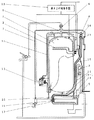
図1は、本発明の実施の形態1における貯湯式給湯機の断面図である。
(Embodiment 1)
FIG. 1 is a cross-sectional view of a hot water storage type water heater in
図1において、1はタンク、2はヒータ、3は給水口を有する減圧弁、4は逃し弁、5は排水バルブ、6は給湯口であり、これらは銅パイプにより連通され、7の外装筐体によりこれらを支える構成となっている。 In FIG. 1, 1 is a tank, 2 is a heater, 3 is a pressure reducing valve having a water supply port, 4 is a relief valve, 5 is a drain valve, and 6 is a hot water supply port. It is configured to support these by the body.
給水口を有する減圧弁3から給水した水道水は給水用パイプ8よりタンク1下部に入り、タンク1内の湯または水を上方に押し上げ、タンク1上部にある湯が給湯用パイプ9から給湯口6に出てくるようになっており、家庭用台所や洗面所、浴室への給湯として使用できるようになっている。
The tap water supplied from the pressure reducing valve 3 having a water supply inlet enters the lower part of the
また、タンク1の下方と上方は循環ポンプ10を有する循環パイプ11により連通されており、沸き上げ制御手段12はヒータ2と循環ポンプ10をコントロールして、タンク上部で約90℃一定の湯を沸かして、いつでも給湯可能な状態を保ちながら、タンク1下部の水を上方に循環させ、全量沸き上げるようにしている。
The lower and upper sides of the
逃し弁4は保持金具13により外装筐体7に固定されて構造的に安定した構成となっており、タケノコ形状となっている逃し弁出口14にゴムホース15が挿入されホースバンド16により固定されている。
The
外装筐体7の最下部には膨張水排水口17があって、ゴムホース15はここに挿入されホースバンド16により固定されている。
An
沸き上げが開始すると、タンク1は水の膨張により内圧が上昇し、逃し弁4が作動し膨張水を逃し弁出口13から排出するようになると、高温の膨張水はゴムホース15を経て膨張水排水口17より器体外に排出される。
When the boiling starts, the internal pressure of the
18は、独立発砲状態に成形されたポリエチレンのチュ−ブからなるさや管であり、逃し弁出口14にゴムホース15が挿入されホースバンド16により固定されている箇所を覆うように保持金具13に固定されており、この内径は、ゴムホース15およびホースバンド16が逃し弁出口14から外れても、これらが中をスム−ズに通過できる大きさとなっており、この時に出る膨張水を全て受け止めることができるとともに、ホースバンド16がゴムホース15に固定された状態でゴムホース15が吹き飛ばされるような場合であっても、破れるなどの損傷がないようになっている。
さらに、さや管18は膨張水排水口17近傍までの長さを有しており、外装筐体7内部
の電子部品や制御電源等に水が飛散してかからないように構成されている。
Further, the
次に以上のような構成の貯湯式給湯機において、冬期の沸き上げ動作について説明する。 Next, in the hot water storage type water heater configured as described above, the heating operation in winter will be described.
深夜の所定時刻になると、沸き上げ制御手段12はヒータ2に通電し、タンク1内の上部の水を約90℃となるまで沸き上げる。そして循環ポンプ10を通電して制御し、タンク1内の下部の水を上方にくみ上げ、上部の水が常に約90℃をキ−プするよう流量合わせをして、タンク1内の水を所定量の湯に沸き上げるようになっている。
At a predetermined time at midnight, the boiling control means 12 energizes the
冬期の場合、深夜時間帯で朝方になるに従って、外気温度は低下し、外装筐体7の外部で残水のある排水バルブ5や膨張水排出口17の出口付近では氷結しており、場合によっては内部通路を閉塞している場合もある。
In the winter season, the outside air temperature decreases as it becomes morning in the midnight hours, and the outside of the
タンク内部は、温度が上がることによって水の膨張が始まり、一定圧力を超えると逃し弁4が作動し膨張水を逃し弁出口13から排出するようになる。
The inside of the tank starts to expand when the temperature rises, and when the pressure exceeds a certain pressure, the
この時、タンク1の上部は約90℃であり、これが膨張水となって逃し弁出口13からゴムホ−ス15を経て膨張水排水口17より器体外に排出されるまでに、温度低下するが、さや管18には高い保温効果があり、著しい温度低下はなく、少なくとも膨張水排出口では膨張水が氷結してしまうことはないというだけでなく、万が一残水の氷結で膨張水排出口17が閉塞状態になっていたとしても、高温の膨張水が氷結した残水を融かし、閉塞していた膨張水排出口17の通水を可能にしてくれる。
At this time, the temperature of the upper part of the
また、万が一膨張水排出口17が閉塞状態のままで、ゴムホ−ス15の内圧が上昇し、ゴムホース15が逃し弁出口14から外れてしまうか、膨れ出したゴムホース15はさらに膨れ続け、最終的にはこの部分が破裂してしまうといった現象が発生した場合でも、膨張水が飛散し周辺の制御電気部品を濡らすことなく、このさや管18内壁をつたって下部に滴下してくれるため、沸き上げ制御手段12の絶縁不良が起因して給湯機そのものが動作不良するといった課題が解決される。
In the unlikely event that the expansion
一方、逃し弁4の出口側を金属配管などによる耐圧構造にしていないのは、膨張水排出口17が閉塞状態にある場合にも、タンク1の内圧が上昇することが無いようにするためであり、逃し弁4の作動でいかなる条件においてもタンク1内圧は一定以上に上がることはない安全構成が実現できており、タンク1を含む全ての部品の故障に対する信頼性を確保することができている。
On the other hand, the reason why the outlet side of the
さらに、逃し弁4はタンク1上部に配され、沸き上げ中には高温の膨張水にさらされており、冬季の凍結で動作不能になる恐れもない。
Furthermore, the
また、従来の技術では貯湯式給湯機の外装筐体7の外部で排水バルブ5や膨張水排出口17に接続された配管には、サーモスタットを備えた凍結予防ヒーターの取り付けと電源を用意しなければならなかったが、さや管18には高い保温効果があり、万が一の残水の氷結も、高温の膨張水が氷を融かし、閉塞していた膨張水排出口17の通水を可能にしてくれるため、これらが不要となり、冬季の消費電力量を抑制する効果もある。
Further, in the conventional technology, the piping connected to the
(実施の形態2)
図2は、本発明の実施の形態2の貯湯式給湯機の断面図である。
(Embodiment 2)
FIG. 2 is a cross-sectional view of a hot water storage type hot water supply apparatus according to
図において、19は給水用パイプであり、タンク1への接合部近傍の曲がり部19−1
は鋭角に曲げられており、パイプがタンク1底面の球Rに沿って密着するよう構成されている。ゴムホ−ス15もまた、上方より急な下り勾配を維持しつつ給水用パイプ19の曲がり部19−1に密着するよう構成され、さや管20は、ゴムホ−ス15を上方より覆うだけでなく、給水用パイプ19の曲がり部19−1に密着する箇所にはスリットが入っており、ゴムホ−ス15とパイプの密着部を覆って保温することができるようになっている。
In the figure,
Is bent at an acute angle, and the pipe is configured to be in close contact with the sphere R on the bottom surface of the
次に、上記のように構成された貯湯式給湯機において、冬期の沸き上げ動作について説明する。 Next, in the hot water storage type water heater configured as described above, the heating operation in winter will be described.
深夜の所定時刻になると、沸き上げ制御手段12はヒータ2に通電し、タンク1内の上部の水を約90℃となるまで沸き上げる。そして循環ポンプ10を通電して制御し、タンク1内の下部の水を上方にくみ上げ、上部の水が常に約90℃をキ−プするよう流量合わせをして、タンク1内の水を所定量の湯に沸き上げるようになっている。
At a predetermined time at midnight, the boiling control means 12 energizes the
冬期の場合、深夜時間帯で朝方になるに従って、外気温度は低下し、外装筐体7の内部であっても、タンク1下部は低温となり、給水用バイプ19の曲がり部19−1はこの影響を受け凍結してしまう場合があり、給水用バイプ19の内部を閉塞させ、タンク1が沸き上っていても、給水できないことからお湯が使えないという不具合が生じていた。
In the winter, the outside air temperature decreases as it becomes morning in the midnight time zone, and even in the
しかしながら、本発明によれば、約90℃の膨張水がゴムホ−ス15を経て膨張水排水口17より器体外に排出されるまでに、給水用パイプ19の曲がり部19−1に密着しているため、ここでの熱伝導によって凍結を防止することができる。その上、さや管18には高い保温効果があり、著しい熱量のロスを抑えることができる。
However, according to the present invention, the expanded water of about 90 ° C. is in close contact with the bent portion 19-1 of the
従来の技術で、給水用バイプ19の曲がり部19−1に装着されていた凍結予防ヒ−タとその制御電源は一般的には出力が0.005kW程度あり、低温時には約10時間通電され、およそ0.05kWhの熱量を必要としていた。
In the conventional technique, the freeze prevention heater and its control power source, which are attached to the bending portion 19-1 of the
本発明によれば、さや管20が保温効果をもっているため、膨張水の放熱ロスを抑えることができており、膨張水の熱量の一部、すなわち1.2kWh中0.05kWhの熱量がゴムホース15より給水用パイプ19に伝達されることで、凍結予防ヒーターなしで十分な効果を得ることが可能となって、冬季の低温時に必要となっていた凍結予防ヒーターの消費電力量を抑制することができる。
According to the present invention, since the
さらに給水用パイプ19への熱量伝達部に熱伝導性が決して高いとはいえないゴム材を使用していることと、熱容量の大きなタンク1にも密着させていることで、膨張水の熱量は十分に残すことができて、膨張水排出口の氷結による閉塞を防止するという効果の両立も図れている。
Furthermore, by using a rubber material that cannot be said to have a high thermal conductivity for the heat quantity transfer part to the
以上のように、本発明に係る貯湯式給湯機は、膨張水の排出管が凍結して閉塞した場合でも、機体内に漏水させることなく、適切に膨張水を外部に排出することができるため、外部に設置する排水機能を有する機器全般に適用することができる。 As described above, the hot water storage type hot water heater according to the present invention can appropriately discharge the expansion water to the outside without causing water leakage into the machine body even when the discharge pipe of the expansion water is frozen and blocked. It can be applied to general equipment having a drainage function installed outside.
1 タンク
4 逃し弁
7 外装筐体
12 沸き上げ制御手段
15 ゴムホ−ス
17 膨張水排出口
18 さや管
DESCRIPTION OF
Claims (3)
Priority Applications (1)
| Application Number | Priority Date | Filing Date | Title |
|---|---|---|---|
| JP2003386653A JP4207756B2 (en) | 2003-11-17 | 2003-11-17 | Hot water storage water heater |
Applications Claiming Priority (1)
| Application Number | Priority Date | Filing Date | Title |
|---|---|---|---|
| JP2003386653A JP4207756B2 (en) | 2003-11-17 | 2003-11-17 | Hot water storage water heater |
Publications (2)
| Publication Number | Publication Date |
|---|---|
| JP2005147549A JP2005147549A (en) | 2005-06-09 |
| JP4207756B2 true JP4207756B2 (en) | 2009-01-14 |
Family
ID=34694285
Family Applications (1)
| Application Number | Title | Priority Date | Filing Date |
|---|---|---|---|
| JP2003386653A Expired - Fee Related JP4207756B2 (en) | 2003-11-17 | 2003-11-17 | Hot water storage water heater |
Country Status (1)
| Country | Link |
|---|---|
| JP (1) | JP4207756B2 (en) |
Cited By (1)
| Publication number | Priority date | Publication date | Assignee | Title |
|---|---|---|---|---|
| US7852524B2 (en) | 2006-01-19 | 2010-12-14 | Ricoh Company, Ltd. | Image reading device and an image forming apparatus |
Families Citing this family (6)
| Publication number | Priority date | Publication date | Assignee | Title |
|---|---|---|---|---|
| JP2007064493A (en) * | 2005-08-29 | 2007-03-15 | Matsushita Electric Ind Co Ltd | Hot water storage tank unit |
| JP2011220404A (en) | 2010-04-07 | 2011-11-04 | Yokohama Rubber Co Ltd:The | Connecting structure for piping |
| CN104110843B (en) * | 2013-04-18 | 2017-02-22 | 广东美的暖通设备有限公司 | Water tank and water heater with same |
| WO2017221793A1 (en) * | 2016-06-23 | 2017-12-28 | パナソニックIpマネジメント株式会社 | Fuel cell system |
| CN110160255B (en) * | 2019-05-28 | 2024-04-16 | 广东万和电气有限公司 | A storage type electric water heater |
| JP2024047681A (en) * | 2022-09-27 | 2024-04-08 | ダイニチ工業株式会社 | Fuel Cell Systems |
-
2003
- 2003-11-17 JP JP2003386653A patent/JP4207756B2/en not_active Expired - Fee Related
Cited By (1)
| Publication number | Priority date | Publication date | Assignee | Title |
|---|---|---|---|---|
| US7852524B2 (en) | 2006-01-19 | 2010-12-14 | Ricoh Company, Ltd. | Image reading device and an image forming apparatus |
Also Published As
| Publication number | Publication date |
|---|---|
| JP2005147549A (en) | 2005-06-09 |
Similar Documents
| Publication | Publication Date | Title |
|---|---|---|
| EP2331882B1 (en) | Adaptive self pumping solar hot water heating system with overheat protection | |
| US5584316A (en) | Hydrothermal stabilizer and expansion tank system | |
| JP4207756B2 (en) | Hot water storage water heater | |
| CN108826683A (en) | A kind of high carbon molecule heating oil electric heater of internal and external screw heat exchange structure | |
| CN203749196U (en) | Safety drinking water system with automatic water adding function | |
| KR20120061199A (en) | A heat exchanger with an auxiliary tank | |
| PT2053951E (en) | Boiler, in particular for a coffee machine | |
| KR100868911B1 (en) | Thermostat of Marine Drainage Pipe | |
| JP2004286261A (en) | Water heater | |
| JP2012032118A (en) | Hot water supply pipe | |
| JP5413328B2 (en) | Water heater | |
| TWI540297B (en) | Automatic drinking water system and its safety control mechanism | |
| JP2007071444A (en) | Water heater | |
| JP6094363B2 (en) | Water heater | |
| CN212390613U (en) | Anti-freezing drainage device and water heater system | |
| EP3480526B1 (en) | Installation for heating and/or for producing domestic hot water in a building | |
| JP2002364924A (en) | Power-saving quick-heating electric water-heater | |
| CN216049352U (en) | Phase change energy storage device and water heating equipment | |
| KR20060019423A (en) | Hot water tank for cold / hot water purifier to prevent hot water backflow | |
| CN102042682B (en) | Electric storage water heater | |
| KR100824411B1 (en) | Direct Heating Electric Boiler | |
| TWI388784B (en) | Electric storage water heater | |
| JP2011056222A (en) | Toilet seat | |
| JP4825147B2 (en) | Water heater | |
| JP2004144382A (en) | Water heater utilizing solar heat |
Legal Events
| Date | Code | Title | Description |
|---|---|---|---|
| A621 | Written request for application examination |
Free format text: JAPANESE INTERMEDIATE CODE: A621 Effective date: 20060823 |
|
| RD01 | Notification of change of attorney |
Free format text: JAPANESE INTERMEDIATE CODE: A7421 Effective date: 20060913 |
|
| A977 | Report on retrieval |
Free format text: JAPANESE INTERMEDIATE CODE: A971007 Effective date: 20080626 |
|
| A131 | Notification of reasons for refusal |
Free format text: JAPANESE INTERMEDIATE CODE: A131 Effective date: 20080701 |
|
| A521 | Written amendment |
Free format text: JAPANESE INTERMEDIATE CODE: A523 Effective date: 20080829 |
|
| TRDD | Decision of grant or rejection written | ||
| A01 | Written decision to grant a patent or to grant a registration (utility model) |
Free format text: JAPANESE INTERMEDIATE CODE: A01 Effective date: 20080930 |
|
| A01 | Written decision to grant a patent or to grant a registration (utility model) |
Free format text: JAPANESE INTERMEDIATE CODE: A01 |
|
| A61 | First payment of annual fees (during grant procedure) |
Free format text: JAPANESE INTERMEDIATE CODE: A61 Effective date: 20081013 |
|
| FPAY | Renewal fee payment (event date is renewal date of database) |
Free format text: PAYMENT UNTIL: 20111031 Year of fee payment: 3 |
|
| FPAY | Renewal fee payment (event date is renewal date of database) |
Free format text: PAYMENT UNTIL: 20121031 Year of fee payment: 4 |
|
| FPAY | Renewal fee payment (event date is renewal date of database) |
Free format text: PAYMENT UNTIL: 20131031 Year of fee payment: 5 |
|
| LAPS | Cancellation because of no payment of annual fees |