JP4207648B2 - Optical subscriber line connection unit and residential termination equipment - Google Patents
Optical subscriber line connection unit and residential termination equipment Download PDFInfo
- Publication number
- JP4207648B2 JP4207648B2 JP2003120540A JP2003120540A JP4207648B2 JP 4207648 B2 JP4207648 B2 JP 4207648B2 JP 2003120540 A JP2003120540 A JP 2003120540A JP 2003120540 A JP2003120540 A JP 2003120540A JP 4207648 B2 JP4207648 B2 JP 4207648B2
- Authority
- JP
- Japan
- Prior art keywords
- circuit
- telephone line
- home
- telephone
- power
- Prior art date
- Legal status (The legal status is an assumption and is not a legal conclusion. Google has not performed a legal analysis and makes no representation as to the accuracy of the status listed.)
- Expired - Fee Related
Links
- 230000003287 optical effect Effects 0.000 title claims description 31
- 238000006243 chemical reaction Methods 0.000 claims description 29
- 238000001514 detection method Methods 0.000 claims description 24
- 239000013307 optical fiber Substances 0.000 claims description 24
- 230000006854 communication Effects 0.000 claims description 20
- 238000004891 communication Methods 0.000 claims description 20
- 230000000903 blocking effect Effects 0.000 claims description 12
- 238000000926 separation method Methods 0.000 description 13
- 230000005540 biological transmission Effects 0.000 description 10
- 238000010586 diagram Methods 0.000 description 9
- 238000010276 construction Methods 0.000 description 5
- 238000011144 upstream manufacturing Methods 0.000 description 3
- 238000000034 method Methods 0.000 description 2
- 230000008054 signal transmission Effects 0.000 description 2
- 230000007175 bidirectional communication Effects 0.000 description 1
- 230000000694 effects Effects 0.000 description 1
- 239000000284 extract Substances 0.000 description 1
- 239000000835 fiber Substances 0.000 description 1
- 238000003780 insertion Methods 0.000 description 1
- 230000037431 insertion Effects 0.000 description 1
Images


Landscapes
- Optical Communication System (AREA)
- Telephonic Communication Services (AREA)
- Small-Scale Networks (AREA)
Description
【0001】
【発明の属する技術分野】
本発明は、光加入者線の接続ユニットおよび宅用終端装置に関し、詳しくは、光加入者線に加入する際の加入者宅での工事負担の軽減などを図るためのものである。
【0002】
【従来の技術】
現在、加入者系通信システムとしてISDN(Integrated Services Digital Network)やADSL(Asymmetric Digital Subscriber line)やFTTH(Fiber to the Home)等の接続形態が知られており、その中でもFTTHは通信速度が高速で通信安定性も高いことから年々普及している。図8はFTTHによる受動光ネットワーク(PON)の構成を示し、光学ライン端末(OLT:Optical Line Terminal)1と各家庭に配置される複数の光学ネットワーク装置(ONU:Optical Network Unit)2とをスターカプラを介して光ファイバーケーブル3で多分岐接続している。光データ回線の伝送フレーム制御方式は、下りフレームは時分割多重(TDM)方式で通信を行う一方、上りフレームは加入者側のトラフィック量に応じて適当なタイムスロットを割り当てることで信号衝突の回避等の制御を行い、通信速度が最大100Mbpsのベストエフォート型の通信を行うようにしている。
【0003】
【特許文献1】
特開平2002−57685号公報
【0004】
【発明が解決しようとする課題】
しかしながら、図8に示すような現在のFTTHの構成では、光学ネットワーク装置(ONU)2を加入者宅内に設置するため、光ファイバーケーブル3を宅内に引き入れるための宅内への立入り工事が必要となり、FTTHの戸建住宅への普及の足かせになっている問題がある。光学ネットワーク装置2を宅外に設置することも考えられるが、その場合には光学ネットワーク装置2への電源供給のための工事に大きな手間が掛かるので、やはり宅内に光学ネットワーク装置2を設置して光ファイバーケーブル3を宅内に引き込まざるを得ないのが現状である。
また、光ファイバーケーブル3を宅内に引き込む際には、家屋の外壁にケーブル挿通用の穴をあけるか、あるいは、エアコンのダクト挿通用の穴まで外壁に沿って光ファイバーケーブル2を引き回す等の面倒が生じると共に、外壁に穴をあける場合には加入者に予め了解を得なければならない面倒も生じる。
さらに、予めLAN配線が敷設された新築住宅以外は、宅内でのケーブル配線は露出配線にならざるを得ず、外観上・機能上の点からも好ましくない。
【0005】
従って、宅内の伝送には既設の配線を利用するのが望まれる。そのようなものには電力線と電話線が考えられる。電力線については、FTTHに見合う高速な伝送方式はまだ法的に認められておらず電話線が有望である。電話線の場合は、既存のアナログ電話との共存できることが必要であり、既存の電話線を使ってアナログ電話とデータ伝送を共存させる方法は、ADSL、VDSLが知られている。しかし、スプリッタのみを使用するこれらの方式を採用するとしても、宅外に設置された光学ネットワーク装置2への電源供給に大変手間がかかる問題は解決されない。
【0006】
本発明は、上記問題に鑑みてなされたもので、宅内工事をせずとも容易に光加入者線に加入することができるようにすることを課題としている。
【0007】
【課題を解決するための手段】
上記課題を解決するため、本発明は、加入者宅に設置し、親局から加入者宅へと配線される光ファイバーケーブルと接続すると共に、上記加入者宅と電話局とを結ぶ電話線に介在させ、宅内電話線と宅外電話線とを中継する接続ユニットであって、
上記接続ユニットは、光ファイバーケーブルと接続されてO/E・E/O変換を行う光電気変換部と、
一側を該光電気変換部と接続されると共に他側を宅内電話線側と接続されてデータの変復調を行う電話線用変復調部と、
上記加入者宅内の電源から上記宅内電話線を通じて供給される直流電力を分離して、上記光電気変換部および上記電話線用変復調部に電力供給するための直流分離部とを備え、
かつ、上記宅内電話線から電力供給されることを検知して上記宅外電話線からの直流成分を遮断する一方、交流成分を通過させることを可能としている直流遮断部を備えていることを特徴とする光加入者線の接続ユニットを提供している。
【0008】
上記O/E変換を行う光電気変換部を備えた接続ユニットを加入者宅の外壁等の屋外に設置すると、光ファイバーケーブルを加入者宅内に引き込まずに済むと共に、接続ユニットは宅内電話線を介して宅用終端装置と通信可能となるので、加入者宅の外壁に穴をあける必要もなくなると共に、宅内への立入り工事も不要とすることができる。
また、接続ユニットを動作させるための電源は、接続ユニットと宅用終端装置との間の信号線となる宅内電話線を利用して宅内側より電源供給するようにしているので、宅外で電源を確保する工事も不要とすることができる。
【0009】
上記宅内電話線は既設電話線であることにより、宅内にケーブルを露出させることなく配線でき、外観上、機能上ともに良好となる。
【0010】
上記接続ユニットには電話局と接続される宅外電話線が接続され、上記宅用終端装置に接続された電話機は、上記宅外電話線を通じたアナログ電話を使用可能としている。
【0011】
上記構成とすると、従来のアナログ電話での通話もそのまま利用できると共に、加入者は、コストパフォーマンスの良いIP電話と、通話品質の安定しているアナログ電話とを状況に応じて使い分けることもでき利便性が向上する。
【0012】
本発明は、加入者宅に設置し、親局から加入者宅へと配線される光ファイバーケーブルと接続する接続ユニットであって、
上記光ファイバーケーブルと接続されてO/E・E/O変換を行う光電気変換部と、
一側を該光電気変換部と接続されると共に他側を宅内電話線側と接続されてデータの変復調を行う電話線用変復調部と、
上記加入者宅内の電源から上記宅内電話線を通じて供給される直流電力を分離して、上記光電気変換部および上記電話線用変復調部に電力供給するための直流分離部とを備えていることを特徴とする光加入者線の接続ユニットを提供している。
【0013】
上記構成とすると、上記親局から光信号が下り送信された場合には、光電気変換部において光ファイバーケーブルからの光信号をデジタル電気信号にO/E変換すると共に、電話線用変復調部において該デジタル電気信号を変調して宅内電話線へと送信することができる。(なお、上り送信の場合はこの逆となる。)
また、直流分離部により、加入者宅内の電源から宅内電話線を通じて供給された直流電力を宅内電話線より分離させ、上記光電気変換部および上記電線用変復調部に駆動電力を供給できるので、宅外において電源確保のための工事を不要とすることが可能となる。
【0014】
さらに、上記のように、本発明の接続ユニットは、電話局と上記加入者宅とを結ぶ電話線に介在させ、宅内電話線と宅外電話線とを中継するように設置され、
上記宅内電話線から電力供給されることを検知して、上記宅外電話線からの直流成分を遮断する一方、交流成分を通過させることを可能としている直流遮断部を備えている。
【0015】
上記構成とすると、宅内電話線からの直流電力が供給される場合には、宅外電話線から供給される直流電力を直流遮断部で遮断されるので、宅内側からの直流電力と宅外側から直流電力が衝突するのを防止することができる。
また、直流遮断部は、直流のみを遮断し、音声信号等を送受するための交流は通過させるので、アナログ電話回線を利用した通話を行うことができる。
【0016】
上記直流遮断部は、上記宅外電話線と上記宅内電話線との間に介在する直流遮断回路と、
該直流遮断回路を迂回して上記宅外電話線と上記宅内電話線とを接続するバイパス回路と、
該バイパス回路に設けられ、上記宅内電話線から電力供給されることを検知してバイパス回路をオフ(開)し、上記宅内電話線からの直流電力を上記光電気変換部および上記電話線用変復調部に電力供給するように切替可能なリレー回路とを備えている。
【0017】
上記構成とすると、宅内電話線からの電力供給を検知した際に、リレー回路によりバイパス回路をオフ(開)することで、宅外電話線から供給される直流電力を直流遮断回路で遮断することができる。また、同時に、リレー回路によりバイパス回路をオフ(開)切替することで、宅内電話線を通じて供給された直流電力を上記光電気変換部および上記電話線用変復調部へ供給することができる。
【0018】
上記電話線を流れる電流極性の反転を検出する極性反転回路と、
上記宅外電話線からの呼出信号を検出するリンガ回路と、
上記宅内電話線の終端側に接続された電話機のオンフック、オフフックおよびダイヤルパルスを発生するフッキング・ダイヤルパルス回路とを備え、
上記宅外電話線からの直流成分を遮断した際に、上記極性反転回路、上記リンガ回路および上記フッキング・ダイヤルパルス回路がオン(閉)されるようにしている。
【0019】
上記構成とすると、宅外電話線から供給される直流を直流遮断回路で遮断すると、電話機側の極性反転機能、リンギング機能、フッキング機能およびダイヤルパルス機能が停止されるので、接続ユニット内において極性反転回路とリンガ回路とフッキング・ダイヤルパルス回路とを備えることで、各機能を代替させて従来通りの電話機能を提供することが可能となる。
【0021】
上記構成とすると、宅内電話線を通じて接続ユニットとの間でアナログ電気信号の送受を行い、電話線用変復調部でデータの変復調をして情報通信機器とデジタル電気信号の送受を行うことができる。そして、宅用終端装置内に電源となる直流供給回路を設けて、直流重畳回路により宅内電話線に直流電力を重畳することで、既存の宅内電話線を用いて接続ユニットに直流電力の供給をすることができる。
【0022】
また、本発明は、上記接続ユニットと上記宅内電話線を介して接続される宅用終端装置であって、
上記宅内電話線側と接続してデータの変復調を行う電話線用変復調部と、
上記接続ユニットへの電源供給源となる直流供給回路と、
上記宅内電話線にデータ通信のための交流電気信号に重ねて上記直流供給回路からの直流電力を重畳する直流重畳回路と、
上記宅外電話線、上記接続ユニット、宅内電話線を通じて受信した電話の呼出信号を上記電話機に送出するリンギング回路と、
上記電話機からの発呼・切断・ダイヤルパルス信号を検出して上記接続ユニットへ送信する発呼・切断・ダイヤルパルス検出回路とを備え、上記加入者宅の内部に配置されることを特徴とする光加入者線の宅用終端装置を提供している。
【0023】
上記構成とすると、電話局と繋がる宅外電話線と接続された接続ユニットから宅内電話線を通じて受信した電話の呼出信号をリンギング回路で電話機に適合した呼出信号として電話機側に送出することができる。
また、発呼・切断・ダイヤルパルス検出回路により電話機からの発呼信号と切断信号を検出して宅内電話線に送信しているので、接続ユニットで電話局側に適合した発呼信号、切断信号、ダイヤルパルスとして宅外電話線に送出することができる。
【0024】
上記直流供給回路から上記宅内電話線に供給される電流の上限値を制限する電流制限回路を備えている。
【0025】
各加入者毎の宅内電話線の敷設状態を完全に把握するのは困難であり、無制限に宅内電話線に電力を供給すると障害を生じる恐れがあるが、上記構成とすると、電流制限回路により、例えば、DC48Vで上限100mAというように制限することで、フェールセーフ機能を持たせることができる。
【0026】
【発明の実施の形態】
本発明の実施形態を図面を参照して説明する。
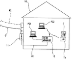
図1は参考実施形態を示し、光加入者系通信システムである受動光ネットワーク(PON:Passive Optical Network)の終端側となる加入者宅10での概略構成図を表している。PONはPDS(Passive Double Star)光データ回線とし1芯双方向通信を時分割多重方式や波長多重方式によりアクセス制御している。
【0027】
親局側に設置された図示しないOLT(Optical Line Terminal)とスターカプラ(図示せず)を介して光ファイバーケーブルOで接続された接続ユニットである接続ONU(Optical Network Unit)11は、加入者宅10の宅外に設置されている。接続ONU11は、既設の電話線W1、W2のうちの宅内電話線W1と接続している一方、宅外電話線W2との接続を絶っている。
宅内電話線W1の終端には宅用終端装置12を接続しており、宅用終端装置12は有線あるいは無線でパソコンP1、P2と接続していると共に、アナログ信号とデジタル信号を統合するIAD(Integrated Access Device)Taを介して電話Tと無線接続している。
【0028】
図2に示すように、接続ONU11は、光ファイバーケーブルOと接続されてO/E・E/O変換を行う光電気変換部13と、光電気変換部13と接続されてデータの変復調を行う電話線用変復調部14と、電話線用変復調部14に接続され電気信号の送受信分離を行うハイブリッド回路15と、宅用終端装置12から供給される直流電力を分離する直流分離回路16と、直流分離回路16と接続されて光電気変換部13および電話線用変復調部14を駆動させる電源回路18とを備えている。
【0029】
宅用終端装置12は、接続ONU11への直流電力の供給を行う直流供給回路23と、データ通信用のアナログ電気信号に直流電源を重畳する直流重畳回路22と、直流重畳回路22と宅内電話線W1との間に設けられ通電する電流上限値をDC48Vで100mAに制限するリミッターである電流制限回路21と、電気信号の送受信分離を行うハイブリッド回路24と、データの変復調を行う電話線用変復調部25と、制御回路26と、パソコン等への接続インターフェースとなる通信回路27とを備えている。
【0030】
次に、接続ONU11および宅用終端装置12でのデータ信号の流れについて説明する。
下り信号については、光ファイバーケーブルOからの光信号を接続ONU11の光電気変換部13でO/E変換してデジタル電気信号化し、電話線用変復調部14でデジタル電気信号を電話線用の変調信号に変換する。該変調信号はハイブリッド回路15で下り送信され、交流である変調信号は直流分離回路16をスルーすると共に保安回路17を通して宅内電話線W1に送信される。
【0031】
宅用終端装置12側では、宅内電話線W1から受信した変調信号を、電流制限回路21および直流重畳回路22をスルーさせて、ハイブリッド回路24で電話線用変復調部25に下り送信される。電話線用変復調回路25では受信した変調信号をデジタル電気信号に変換して制御回路26に送信し、通信回路27より無線やLANケーブルを介してパソコンPC1、PC2あるいは/および電話機TのIADにデータ送信する。
なお、上り信号については、この下り信号の流れの逆となるだけなので説明を省略する。また、この光ファイバーケーブルOを通じたデータ通信は、IP電話の音声データ信号の送受信としても利用される。
【0032】
次に、宅用終端装置12から接続ONU11への電源供給の流れについて説明する。
宅用終端装置12は、加入者宅10の電源コンセントより得た電力を直流供給回路23で交流から直流に変換し、直流重畳回路22によりデータ信号が送受されるラインに直流電力を重畳する。該直流電力は、例えば、電流上限値がDC48Vで100mA以下である場合に電流制限回路21を通過して宅内電話線W1に送出される一方、それを超える場合には電流制限回路12で遮断されて宅内電話線W1には送出されない。
宅内電話線W1から接続ONU11に供給された直流電力は、保安回路17を通して直流分離回路16にてデータ信号を送受するラインから分離されて電源回路18に供給され、電源回路18から光電気変換部13と電話線用変復調部14へ駆動電力として供給される。
【0033】
上記構成とすると、O/E・E/O変換を行う光電気変換部を有する接続ONU11を加入者宅10外に設置しているので、光ファイバーケーブルOを加入者宅10内に引き込まずに済むと共に、接続ONU11は宅内電話線W1を介して宅用終端装置12と通信可能となるので、加入者宅10の外壁に穴をあけたり、加入者宅10内への立入り工事することを不要にできる。
かつ、接続ONU11の動作電源は、接続ONU11と宅用終端装置12との間の信号線とされる宅内電話線W1を共用して供給されるので、宅外で電源を確保する工事も不要にできる。しかも、既設電話線である宅内電話線W1を利用するので、加入者宅10内にケーブルを露出させずに配線できるので、外観が良く、機能性にも優れる。
なお、宅用終端装置12に内蔵される直流供給部23、直流重畳回路22および電流制限回路21は、外付タイプとしてもよいことは言うまでもない。
【0034】
図3乃至図6は第1実施形態を示す。
上記参考実施形態との相違点は、接続ONU30が宅外電話線W2にも接続されている点である。
【0035】
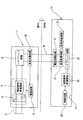
図3に示すように、接続ONU30は、光ファイバーケーブルOと接続されO/E・E/O変換を行う光電気変換部31と、光電気変換部31と接続されてデータの変復調を行う電話線用変復調部32と、各種回路の制御を統括する制御部33と、電話線用変復調部32に接続され電気信号の送受信分離を行うハイブリッド回路35と、アナログ電気信号の高周波数成分を通過させるHPF(high pass filter)36とを備えている。
【0036】
また、宅内電話線W1と宅外電話線W2との間の中継位置には、宅外電話線W2から供給される直流電力を遮断すると共に交流を通過させる直流遮断回路40と、直流遮断回路40を迂回するバイパス回路45と、バイパス回路45のオン(閉)・オフ(開)を行うリレー回路R1と、リレー回路R1のオフ(開)時に宅内電話線W1側と導通され直流電力を分離抽出する直流分離回路41と、直流分離回路41と接続されて光電気変換部31、電話線用変復調部32および制御部33を含む中央処理部46に電力供給する電源回路42とを備えている。
【0037】
直流分離回路40の下位側には、アナログ電気信号の低周波数成分と直流電力を通過させるLPF(low pass filter)37と、LPF37の下位側の宅内電話線W1より分岐し、後述する宅用終端装置50から送信される特定の周波数成分を通過させるBPF(band pass filter)38と、BPF38を通過した信号によりリレー回路R1の開閉駆動を制御すると共に、リレー回路R1の開閉完了通知を宅用終端装置50側に返信するリレー信号検出・駆動・ループバック回路39とを備えている。
【0038】
直流分離回路の上位側には、電話線W1、W2を流れる電流極性の反転を検出すると共に、宅外電話線W2からの呼出信号を検出する極性・リンガ検出回路44と、後述する宅用終端装置50の終端側に接続された電話機のオンフックおよびオフフック・ダイヤルパルスを発生するフッキング・ダイヤルパルス回路43と、フッキング・ダイヤルパルス回路43と宅外電話線W2との導通をオン・オフするリレー回路R2と、極性・リンガ検出回路44と宅外電話線W2との導通をオン・オフするリレー回路R3とを備えている。
【0039】
次に、図4に示すように、宅用終端装置50は、接続ONU30への直流電力の供給を行う直流供給回路53と、データ通信用の電気信号に直流電源を重畳する直流重畳回路52と、直流重畳回路52と宅内電話線W1との間に設けられ通電する電流上限値を例えばDC48Vで100mAに制限する電流制限回路31と、アナログ電気信号の高周波数成分を通過させるHPF(high pass filter)54と、電気信号の送受信分離を行うハイブリッド回路55と、データの変復調を行う電話線用変復調部56と、各種回路の制御を統括する制御回路59と、パソコン等への接続インターフェースとなる通信回路63とを備えている。
【0040】
また、HPF54の上位側で分岐して接続された低周波数成分および直流成分を通過させるLPF(low pass filter)60と、LPF60の下位に接続されて接続ONU30から受信した着呼信号を検出し電話機に適合した着呼信号を送出するリンギング回路61と、リンギング回路61の下位に接続され電話機からの発呼・切断信号、ダイヤルパルスを検出して制御回路59を通じて接続ONU30へ発呼・切断信号、ダイヤルパルスを送信する発呼・切断・ダイヤルパルス検出回路62とを備えている。
発呼・切断・ダイヤルパルス検出回路62はリレー回路R4を介してケーブルW3で電話機に接続されていると共に、リレー回路R4により発呼・切断検出回路62と電話機との導通がオフ(開)された際に、リンギング回路61と発呼・切断検出回路62とを迂回してケーブルW3とLPF60とを接続するバイパス回路64を設けている。
【0041】
また、HPF54の上位側で分岐して接続された特定の周波数成分を通過させるBPF(band pass filter)57と、BPF57の下位に接続され、接続ONU30のリレー信号検出・駆動・ループバック回路39との間で信号の送受を行うリレー信号送受信部58とを備えている。
【0042】
次に、光ファイバーケーブルOを通じたデータ通信おける接続ONU30および宅用終端装置50での信号の流れについて説明する。
下り信号については、光ファイバーケーブルOからの光信号を接続ONU30の光電気変換部31でO/E変換してデジタル電気信号化し、電話線用変復調部32でデジタル電気信号を高周波の変調信号に変換する。該変調信号はハイブリッド回路35で下り送信されると共にHPF36を通過して宅内電話線W1に送信される。
宅用終端装置50では、宅内電話線W1から受信した変調信号を、電流制限回路51および直流重畳回路52をスルーさせると共に、HPF54を通過してハイブリッド回路55で電話線用変復調部56に下り送信される。電話線用変復調回路56では受信した変調信号をデジタル電気信号に復調して制御回路59に送信し、通信回路63より無線やLANケーブルを介してパソコンにデータ送信する。
なお、上り信号については、下り信号の流れの逆となるだけなので説明を省略する。また、この光ファイバーケーブルOを通じたデータ通信は、IP電話の音声データ信号の送受信としても利用される。
【0043】
次に、宅用終端装置50から接続ONU30への電源供給の流れについて説明する。
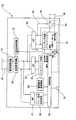
先ず、宅用終端装置50に電源が供給されると、図4に示すように、制御回路59によりリレー信号送受信部58から宅内電話線W1に電源供給開始を知らせる通知信号が送信される。該通知信号は、BPF58およびBPF38が通過させる設定周波数の信号であり、接続ONU30のリレー信号検出・駆動・ループバック回路39で受信して、図3に示す状態から図5に示す状態へとリレー回路R1を切替させる。
【0044】
そして、リレー信号検出・駆動・ループバック回路39は、リレー回路R1の切替を成功したことを知らせる完了通知を宅内電話線W1にループバック送信する。宅用終端装置50はこの完了通知をBPF57を通してリレー信号送受信部58で受信して、制御回路59より直流供給回路53に電力供給開始のトリガー信号が送信されると共に、リレー回路R4を図6の状態に切替する。
【0045】
直流供給回路53は、加入者宅の電源コンセントより得た電力を交流から直流に変換して直流重畳回路52に電力供給し、直流重畳回路52によりデータ信号が送受されるラインに直流電力を重畳する。該直流電力は、電流上限値が例えばDC48Vで100mA以下である場合に電流制限回路51を通過して宅内電話線W1に送出される一方、それを超える場合には電流制限回路51で遮断されて宅内電話線W1には送出されない。
宅内電話線W1から接続ONU30に供給された直流電力はLPF37を通過し、バイパス回路45およびリレー回路R1を介して直流分離回路41で直流成分を分離して電源回路42に供給され、電源回路42により中央処理部46に電力供給されて、制御部33によりリレーR2、R3が図5のようにオン(閉)とされる。
【0046】
次に、接続ONU30に宅用終端装置50から電力が供給された状態における、アナログ電話の着信時の流れについて説明する。
図5に示すように、宅外電話線W2からの着呼信号を極性・リンガ検出回路44で検出し、制御部33に着呼検出信号を送信する。制御部33から、電話線用変復調部32→ハイブリッド回路35→HPF36という流れで宅内電話線W1に着呼信号が送信される。
宅用終端装置50では、図6に示すように、上記着呼信号が、電流制限回路51→直流重畳回路52→HPF54→ハイブリッド回路55→電話線用変復調部56と流れ、電話線用変復調部56で復調されて制御回路59を経てリンギング回路61により、ケーブルW3に電話機に適合した呼出信号を送信する。
【0047】
ケーブルW3の終端側に接続された電話機の受話器が上げられてオフフック状態とされると、オフフック信号が発呼・切断・ダイヤルパルス検出回路62→制御回路59→電話線用変復調部56→ハイブリッド回路55→HPF54→直流重畳回路52→電流制限回路51→宅内電話線W1→HPF36→ハイブリッド回路35→電話線用変復調部32→制御部33→フッキング・ダイヤルパルス回路43と流れて、フッキング回路43により電話局側に適合したオフフック信号が宅外電話線W2に送出され、通話可能となる。通話時の音声信号(交流)は、宅外電話線W2から直流遮断回路40をスルーして宅内電話線W1に流れ、宅用終端装置50内では電流制限回路51→直流重畳回路52→LPF60→リンギング回路61→発呼・切断・ダイヤルパルス検出回路62→ケーブルW3を経て電話機へと流れて通話可能となる。また、通話中の課金情報等を通知するための極性反転は、極性・リンガ検出回路44により検出・出力している。
【0048】
次に、接続ONU30に宅用終端装置50から電力が供給された状態における、アナログ電話の発信時の流れについて説明する。
電話機の受話器が上げられオフフック状態となると、オフフック信号が発呼・切断検出回路62→制御回路59→電話線用変復調部56→ハイブリッド回路55→HPF54→直流重畳回路52→電流制限回路51→宅内電話線W1→HPF36→ハイブリッド回路35→電話線用変復調部32→制御部33→フッキング・ダイヤルパルス回路43と送信され、オフフック信号が宅外電話線W2に送出されて電話機にはオフフック音が発音される。
【0049】
相手先番号がダイヤルされると、同様に、発呼・切断・ダイヤルパルス検出回路62→制御回路59→電話線用変復調部56→ハイブリッド回路55→HPF54→直流重畳回路52→電流制限回路51→宅内電話線W1→HPF36→ハイブリッド回路35→電話線用変復調部32→制御部33→フッキング・ダイヤルパルス回路43と送信され、発呼信号が宅外電話線W2に送出され、相手先が出ると、音声信号(交流)が宅外電話線W2から直流遮断回路40をスルーして宅内電話線W1に流れ通話可能となる。
【0050】
また、電話機の受話器を置いてオンフック状態とすると、切断信号が発呼・切断・ダイヤルパルス検出回路62→制御回路59→電話線用変復調部56→ハイブリッド回路55→HPF54→直流重畳回路52→電流制限回路51→宅内電話線W1→HPF36→ハイブリッド回路35→電話線用変復調部32→制御部33→フッキング・ダイヤルパルス回路43と送信されて、宅外電話線W2に通話終了が送出される。
【0051】
次に、宅用終端装置50から接続ONU30への電力供給が停止され、アナログ電話のみが使用可能である状態での信号の流れについて説明する。
宅用終端装置50からの電力供給が停止された状態では、接続ONU30のリレー回路R1は図3に示す状態となっていると共に、宅用終端装置50のリレー回路R4は図4に示す状態となっている。
【0052】
即ち、宅外電話線W2と電話機へ接続されるケーブルW3との間では、下りは、宅外電話線W2→バイパス回路45→LPF37→宅内電話線W1→電流制限回路51→直流重畳回路52→LPF60→バイパス回路64→ケーブルW3の流れで通電が為される。(上りはこの逆)
よって、宅用終端装置50の電源を入れていない場合、或いは、停電の場合に、宅用終端装置50と接続ONU30への電力供給が停止しても、従来のアナログ電話が可能となるように確保されている。
【0053】
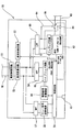
図7は第2実施形態を示す。
第1実施形態との相違点は、接続ONU30’のバイパス回路45’の接続位置を変更している点である。(なお、宅用終端装置50は第1実施形態と同様とする。)
【0054】
バイパス回路45’は、直流遮断回路40だけでなくフッキング・ダイヤルパルス回路43および極性・リンガ検出回路44もまとめて迂回していると共に、バイパス回路45’の上位側と宅外電話線W2との接続部にリレー回路R5を設けている。
接続ONU30’に宅内電話線W1を介して宅用終端装置から電力が供給されていない場合には、図7に示すように、バイパス回路45’がリレー回路R1、R5で閉じられた状態となり、宅外電話線W2→バイパス回路45’→LPF37→宅内電話線W1→電流制限回路51→直流重畳回路52→LPF60→バイパス回路64→ケーブルW3の流れでアナログ電話が可能となるように確保されている。
【0055】
一方、接続ONU30’に宅内電話線W1を介して宅用終端装置から電力が供給された場合には、第1実施形態と同様に、リレー信号検出・駆動・ループバック回路39によりリレー回路R1が切り替えられてバイパス回路45’がオフ(開)されると共に、リレー回路R5が切り替えられて宅外電話線W2と極性・リンガ検出回路44、フッキング・ダイヤルパルス回路43および直流遮断回路40への通電が図られる。
なお、他の構成は第1実施形態と同様であるため説明を省略する。
【0056】
【発明の効果】
以上の説明より明らかなように、本発明によれば、O/E・E/O変換を行う光電気変換部を備えた接続ユニットを加入者宅の外壁等の屋外に設置すると、光ファイバーケーブルの加入者宅内への引き込みが不要となると共に、接続ユニットは宅内電話線を介して宅用終端装置と通信可能となるので、加入者宅の外壁にケーブル挿通用穴をあける必要がなくなり、宅内への立入り工事も不要となる。また、接続ユニットの動作電源は、接続ユニットと宅用終端装置との間の信号線となる宅内電話線を利用して宅内側より供給するので、宅外で電源を確保する工事も不要とできる。
【図面の簡単な説明】
【図1】 本発明の参考実施形態の光加入者線の配線システムの構成図である。
【図2】 参考実施形態の接続ユニットおよび宅用終端装置の回路構成図である。
【図3】 第1実施形態の接続ユニットの回路構成図である。
【図4】 第1実施形態の宅用終端装置の回路構成図である。
【図5】 第1実施形態の接続ユニットのリレー回路が切替された回路構成図である。
【図6】 第1実施形態の宅用終端装置のリレー回路が切替された回路構成図である。
【図7】 第2実施形態の接続ユニットの回路構成図である。
【図8】 従来例を示す図面である。
【符号の説明】
10 加入者宅
11、30 接続ONU(接続ユニット)
12、50 宅用終端装置
13、31 光電気変換部
14、32、56 電話線用変復調部
15、24、35、55 ハイブリッド回路
16、41 直流分離回路
18、42 電源回路
21、51 電流制限回路
22、52 直流重畳回路
23、53 直流供給回路
26、59 制御回路
27、63 通信回路
39 リレー信号検出・駆動・ループバック回路
40 直流遮断回路
43 フッキング・ダイヤルパルス回路
44 極性・リンガ検出回路
45、64 バイパス回路
61 リンギング回路
62 発呼・切断・ダイヤルパルス回路
R1、R2、R3、R4 リレー回路
O 光ファイバーケーブル
T 電話機
W1 宅内電話線
W2 宅外電話線[0001]
BACKGROUND OF THE INVENTION
The present invention provides an optical subscriber line.ContactMore specifically, the connection unit and the home termination device are intended to reduce the construction burden at the subscriber's home when subscribing to the optical subscriber line.
[0002]
[Prior art]
Currently, connection systems such as ISDN (Integrated Services Digital Network), ADSL (Asymmetric Digital Subscriber line), and FTTH (Fiber to the Home) are known as subscriber communication systems. Among them, FTTH has a high communication speed. It has become popular year after year because of its high communication stability. FIG. 8 shows a configuration of a passive optical network (PON) based on FTTH, which includes an optical line terminal (OLT) 1 and a plurality of optical network units (ONUs) 2 arranged in each home. The multi-branch connection is made by an optical fiber cable 3 through a coupler. The transmission frame control system for optical data lines uses a time division multiplexing (TDM) system for downstream frames, while avoiding signal collision by allocating appropriate time slots for upstream frames according to the amount of traffic on the subscriber side. Etc., and the best-effort type communication with a maximum communication speed of 100 Mbps is performed.
[0003]
[Patent Document 1]
Japanese Patent Laid-Open No. 2002-57685
[0004]
[Problems to be solved by the invention]
However, in the current FTTH configuration as shown in FIG. 8, since the optical network unit (ONU) 2 is installed in the subscriber's home, it is necessary to enter the home in order to draw the optical fiber cable 3 into the home. There is a problem that has hindered the spread of detached houses. Although it is conceivable to install the
Further, when the optical fiber cable 3 is pulled into the house, troubles such as making a hole for inserting the cable in the outer wall of the house or drawing the
Further, except for new houses where LAN wiring is laid in advance, cable wiring in the house must be exposed wiring, which is not preferable from the viewpoint of appearance and function.
[0005]
Therefore, it is desirable to use existing wiring for in-home transmission. Such can be power lines and telephone lines. As for the power line, a high-speed transmission system suitable for FTTH has not yet been legally approved, and a telephone line is promising. In the case of a telephone line, it is necessary to be able to coexist with an existing analog telephone, and ADSL and VDSL are known as methods for coexisting an analog telephone and data transmission using the existing telephone line. However, even if these methods using only the splitter are adopted, the problem that the power supply to the
[0006]
The present invention has been made in view of the above problems, and an object of the present invention is to make it possible to easily join an optical subscriber line without carrying out home construction.
[0007]
[Means for Solving the Problems]
In order to solve the above problems, the present invention provides:Installed in the subscriber's home, connected to the optical fiber cable wired from the master station to the subscriber's home, and interposed in the telephone line connecting the subscriber's home and the telephone station, A connection unit that relays
The connection unit is connected to an optical fiber cable to perform an O / E / E / O conversion;
A telephone line modulation / demodulation unit that is connected to the photoelectric conversion unit on one side and connected to the telephone line side on the other side to modulate / demodulate data;
DC power supplied from the power source in the subscriber's home through the home telephone line is separated, and a DC separator for supplying power to the photoelectric converter and the telephone line modem is provided.
In addition, a DC blocking unit that detects that power is supplied from the in-house telephone line and blocks the DC component from the outside telephone line while allowing an AC component to pass therethrough is provided. Optical subscriber line connection unitIs provided.
[0008]
UpOConnection unit with photoelectric conversion unit that performs E / E conversionofOutsideOutdoor such as wallsInstall inWhenThe optical fiber cable does not need to be pulled into the subscriber's home, and the connection unit can communicate with the home terminal device via the home telephone line, so there is no need to make a hole in the outer wall of the subscriber's home and No on-site construction is required.
In addition, the power source for operating the connection unit is supplied from the inside of the house using a home telephone line as a signal line between the connection unit and the home terminal device. It is possible to eliminate the need for construction.
[0009]
Since the above-mentioned home telephone line is an existing telephone line, it can be wired without exposing the cable in the house, and both the appearance and the function are good.
[0010]
The connection unit is connected to an external telephone line connected to a telephone station, and the telephone connected to the home terminal device can use an analog telephone through the external telephone line.
[0011]
With the above configuration, conventional analog telephone calls can be used as they are, and subscribers can use IP telephones with good cost performance and analog telephones with stable call quality, depending on the situation. Improves.
[0012]
The present invention is a connection unit that is installed in a subscriber's house and connected to an optical fiber cable wired from the master station to the subscriber's house,
A photoelectric conversion unit connected to the optical fiber cable for O / E / E / O conversion;
A telephone line modulation / demodulation unit that is connected to the photoelectric conversion unit on one side and connected to the telephone line side on the other side to modulate / demodulate data;
A DC separation unit for separating DC power supplied from the power source in the subscriber's home via the home telephone line and supplying power to the photoelectric conversion unit and the telephone line modulation / demodulation unit; An optical subscriber line connection unit is provided.
[0013]
With the above configuration, when an optical signal is transmitted downstream from the master station, the optical signal from the optical fiber cable is O / E converted into a digital electric signal in the photoelectric conversion unit, and the modem for the telephone line A digital electrical signal can be modulated and transmitted to a home phone line. (The reverse is true for uplink transmission.)
Further, the DC separation unit can separate the DC power supplied from the power source in the subscriber's home via the home phone line from the home phone line and supply the driving power to the photoelectric conversion unit and the wire modulation / demodulation unit. It is possible to eliminate the need for work for securing the power supply outside.
[0014]
Furthermore, as described above, the connection unit of the present invention isIt is installed in a telephone line connecting the telephone office and the above subscriber's house to relay the telephone line inside the house and the outside telephone line.,
A DC blocking unit is provided that detects that power is supplied from the home telephone line and blocks the DC component from the outside telephone line while allowing the AC component to pass therethrough.
[0015]
With the above configuration, when DC power is supplied from the home phone line, the DC power supplied from the outside phone line is blocked by the DC blocking unit. It is possible to prevent the DC power from colliding.
Further, since the direct current blocking unit blocks only direct current and allows alternating current for transmitting and receiving voice signals and the like to pass therethrough, it is possible to make a call using an analog telephone line.
[0016]
The DC blocking unit includes a DC blocking circuit interposed between the outside telephone line and the inside telephone line;
A bypass circuit that bypasses the DC blocking circuit and connects the outside telephone line and the inside telephone line;
The bypass circuit is provided in the bypass circuit, detects that power is supplied from the home telephone line, and turns off (opens) the bypass circuit, and converts the DC power from the home telephone line to the photoelectric conversion unit and the modem for the telephone line. And a relay circuit that can be switched to supply power to the unit.
[0017]
With the above configuration, when the power supply from the home telephone line is detected, the DC power supplied from the external telephone line is cut off by the DC cut-off circuit by turning off (opening) the bypass circuit by the relay circuit. Can do. At the same time, by switching off (opening) the bypass circuit by the relay circuit, it is possible to supply the DC power supplied through the home telephone line to the photoelectric conversion unit and the telephone line modulation / demodulation unit.
[0018]
A polarity reversing circuit for detecting reversal of the current polarity flowing through the telephone line;
A ringer circuit for detecting a call signal from the outside telephone line;
A hooking dial pulse circuit for generating on-hook, off-hook and dial pulses of a telephone connected to the terminal side of the home telephone line;
When the DC component from the outside telephone line is cut off, the polarity inversion circuit, the ringer circuit and the hooking dial pulse circuit are turned on (closed).
[0019]
With the above configuration, the polarity inversion function, ringing function, hooking function and dial pulse function on the telephone side are stopped when the DC supplied from the outside telephone line is interrupted by the DC cutoff circuit. By providing a circuit, a ringer circuit, and a hooking dial pulse circuit, it becomes possible to provide a conventional telephone function by substituting each function.
[0021]
With the above configuration, analog electrical signals can be transmitted / received to / from the connection unit through the home telephone line, and data can be modulated / demodulated by the telephone line modulation / demodulation unit to exchange digital electrical signals with the information communication device. Then, a DC power supply circuit serving as a power source is provided in the home terminal device, and DC power is superimposed on the home phone line by the DC superimposing circuit, so that DC power is supplied to the connection unit using the existing home phone line. can do.
[0022]
Further, the present invention is a home terminal device connected to the connection unit via the home telephone line,
A telephone line modulation / demodulation unit that performs modulation / demodulation of data by connecting to the residential telephone line side;
A DC supply circuit serving as a power supply source to the connection unit;
A DC superposition circuit that superimposes DC power from the DC supply circuit on the home telephone line superimposed on an AC electrical signal for data communication;
A ringing circuit for sending a telephone ringing signal received through the outside telephone line, the connection unit, and the telephone line to the telephone;
A call / disconnect / dial pulse detection circuit that detects a call / disconnect / dial pulse signal from the telephone and transmits the signal to the connection unit, and is arranged inside the subscriber's house. It provides a home terminal device for optical subscriber lines.
[0023]
With the above configuration, the telephone ringing signal received through the telephone line from the connecting unit connected to the telephone line connected to the telephone station can be transmitted to the telephone side as a ringing signal suitable for the telephone by the ringing circuit.
In addition, since the call signal and the disconnection signal are detected by the call / disconnect / dial pulse detection circuit and transmitted to the home phone line, the call signal and the disconnect signal suitable for the telephone station side at the connection unit The dial pulse can be sent to the outside telephone line.
[0024]
A current limiting circuit for limiting an upper limit value of the current supplied from the DC supply circuit to the home telephone line;
[0025]
It is difficult to fully grasp the laying state of the home phone line for each subscriber, and there is a risk of causing trouble if power is supplied to the home phone line without limitation. For example, a fail-safe function can be provided by limiting the upper limit to 100 mA at DC 48V.
[0026]
DETAILED DESCRIPTION OF THE INVENTION
Embodiments of the present invention will be described with reference to the drawings.
Figure 1referenceThe embodiment is shown and the schematic block diagram in the
[0027]
A connection ONU (Optical Network Unit) 11, which is a connection unit connected by an optical fiber cable O via a star coupler (not shown) and an OLT (Optical Line Terminal) (not shown) installed on the master station side, It is installed outside 10 homes. The
A
[0028]
As shown in FIG. 2, the
[0029]
The
[0030]
Next, the flow of data signals in the
For the down signal, the optical signal from the optical fiber cable O is O / E converted by the
[0031]
On the
Note that the upstream signal is the reverse of the downstream signal flow, and therefore the description thereof is omitted. The data communication through the optical fiber cable O is also used for transmission / reception of voice data signals of IP telephones.
[0032]
Next, the flow of power supply from the
The
The DC power supplied from the home telephone line W1 to the
[0033]
With the above configuration, since the
In addition, since the operating power of the
Needless to say, the
[0034]
3 to 6 show the first1An embodiment is shown.
Reference aboveThe difference from the embodiment is that the
[0035]
As shown in FIG. 3, the
[0036]
Further, at a relay position between the home phone line W1 and the outside phone line W2, a
[0037]
On the lower side of the
[0038]
On the upper side of the DC separation circuit, a polarity /
[0039]
Next, as shown in FIG. 4, the
[0040]
Further, a low-pass filter (LPF) 60 that passes through a low-frequency component and a DC component that are branched and connected on the upper side of the
The call / disconnection / dial
[0041]
Also, a BPF (band pass filter) 57 that passes a specific frequency component branched and connected on the upper side of the
[0042]
Next, the flow of signals in the
For the down signal, the optical signal from the optical fiber cable O is O / E converted by the
In the
As for the upstream signal, the description is omitted because it is just the reverse of the downstream signal flow. The data communication through the optical fiber cable O is also used for transmission / reception of voice data signals of IP telephones.
[0043]
Next, the flow of power supply from the
First, when power is supplied to the
[0044]
Then, the relay signal detection / drive /
[0045]
The
The DC power supplied from the home telephone line W1 to the
[0046]
Next, a description will be given of a flow when an incoming analog phone call is received in a state where power is supplied from the
As shown in FIG. 5, an incoming call signal from the outside
In the
[0047]
When the handset of the telephone connected to the terminal side of the cable W3 is lifted to be in an off-hook state, an off-hook signal is generated by the call / disconnect / dial
[0048]
Next, a flow at the time of outgoing of an analog telephone in a state where power is supplied from the
When the telephone handset is lifted and is in an off-hook state, an off-hook signal is generated by the call /
[0049]
Similarly, when the destination number is dialed, the calling / disconnecting / dial
[0050]
When the telephone handset is put on the hook state, the disconnection signal is transmitted to the calling / disconnecting / dial
[0051]
Next, a signal flow in a state where power supply from the
When the power supply from the
[0052]
That is, between the outside telephone line W2 and the cable W3 connected to the telephone, the downside telephone line W2
Therefore, even if the power supply to the
[0053]
FIG.2An embodiment is shown.
First1The difference from the embodiment is that the connection position of the
[0054]
The bypass circuit 45 'bypasses not only the
When power is not supplied to the
[0055]
On the other hand, when power is supplied to the
Other configurations are1Since it is the same as that of embodiment, description is abbreviate | omitted.
[0056]
【The invention's effect】
As is apparent from the above description, according to the present invention, a connection unit including an optoelectric conversion unit that performs O / E / E / O conversion is provided to a subscriber.Outdoor such as the outer wall of the houseInstallWhenThe optical fiber cable does not need to be pulled into the subscriber's home, and the connection unit can communicate with the home terminal device via the home phone line. Therefore, it is necessary to make a cable insertion hole in the outer wall of the subscriber's home. Eliminates the need for on-site construction. In addition, since the operating power of the connection unit is supplied from the inside of the house using a home telephone line that is a signal line between the connection unit and the home terminal device, it is possible to eliminate the need to secure power outside the house. .
[Brief description of the drawings]
FIG. 1 of the present inventionreference1 is a configuration diagram of an optical subscriber line wiring system according to an embodiment. FIG.
[Figure 2]referenceIt is a circuit block diagram of the connection unit and home terminal device of an embodiment.
[Figure 3]1It is a circuit block diagram of the connection unit of embodiment.
FIG. 41It is a circuit block diagram of the home termination apparatus of embodiment.
FIG. 51It is the circuit block diagram by which the relay circuit of the connection unit of embodiment was switched.
FIG. 61It is the circuit block diagram by which the relay circuit of the home termination apparatus of embodiment was switched.
FIG. 72It is a circuit block diagram of the connection unit of embodiment.
FIG. 8 is a diagram showing a conventional example.
[Explanation of symbols]
10 Subscriber's house
11, 30 Connection ONU (connection unit)
12, 50 Home terminal equipment
13, 31 Photoelectric converter
14, 32, 56 Telephone line modem
15, 24, 35, 55 Hybrid circuit
16, 41 DC separation circuit
18, 42 Power circuit
21, 51 Current limit circuit
22, 52 DC superposition circuit
23, 53 DC supply circuit
26, 59 Control circuit
27, 63 Communication circuit
39 Relay signal detection / drive / loopback circuit
40 DC cutoff circuit
43 hooking dial pulse circuit
44 Polarity / Ringer detection circuit
45, 64 Bypass circuit
61 Ringing circuit
62 Calling / disconnecting / dial pulse circuit
R1, R2, R3, R4 Relay circuit
O Optical fiber cable
T telephone
W1 Home phone line
W2 Outside phone line
Claims (4)
上記接続ユニットは、光ファイバーケーブルと接続されてO/E・E/O変換を行う光電気変換部と、
一側を該光電気変換部と接続されると共に他側を宅内電話線側と接続されてデータの変復調を行う電話線用変復調部と、
上記加入者宅内の電源から上記宅内電話線を通じて供給される直流電力を分離して、上記光電気変換部および上記電話線用変復調部に電力供給するための直流分離部とを備え、
かつ、上記宅内電話線から電力供給されることを検知して上記宅外電話線からの直流成分を遮断する一方、交流成分を通過させることを可能としている直流遮断部を備えていることを特徴とする光加入者線の接続ユニット。 Installed in the subscriber's home, connected to the optical fiber cable wired from the master station to the subscriber's home, and interposed in the telephone line connecting the subscriber's home and the telephone station, A connection unit that relays
The connection unit is connected to an optical fiber cable to perform an O / E / E / O conversion;
A telephone line modulation / demodulation unit that is connected to the photoelectric conversion unit on one side and connected to the telephone line side on the other side to modulate / demodulate data;
DC power supplied from the power source in the subscriber's home through the home telephone line is separated, and a DC separator for supplying power to the photoelectric converter and the telephone line modem is provided.
In addition, a DC blocking unit that detects that power is supplied from the in-house telephone line and blocks the DC component from the outside telephone line while allowing an AC component to pass therethrough is provided. An optical subscriber line connection unit .
該直流遮断回路を迂回して上記宅外電話線と上記宅内電話線とを接続するバイパス回路と、
該バイパス回路に設けられ、上記宅内電話線から電力供給されることを検知してバイパス回路をオフ(開)し、上記宅内電話線からの直流電力を上記光電気変換部および上記電話線用変復調部に電力供給するように切替可能なリレー回路とを備えている請求項1に記載の光加入者線の接続ユニット。 The DC blocking unit includes a DC blocking circuit interposed between the outside telephone line and the inside telephone line;
A bypass circuit that bypasses the DC blocking circuit and connects the outside telephone line and the inside telephone line;
The bypass circuit is provided in the bypass circuit, detects that power is supplied from the home telephone line, and turns off (opens) the bypass circuit, and converts the DC power from the home telephone line to the photoelectric conversion unit and the modem for the telephone line. The optical subscriber line connection unit according to claim 1, further comprising: a relay circuit that can be switched to supply power to the unit .
上記宅外電話線からの呼出信号を検出するリンガ回路と、A ringer circuit for detecting a call signal from the outside telephone line;
上記宅内電話線の終端側に接続された電話機のオンフック、オフフックおよびダイヤルパルスを発生するフッキング・ダイヤルパルス回路とを備え、A hooking dial pulse circuit for generating on-hook, off-hook and dial pulses of a telephone connected to the terminal side of the home telephone line;
上記宅外電話線からの直流成分を遮断した際に、上記極性反転回路、上記リンガ回路および上記フッキング・ダイヤルパルス回路がオン(閉)されるようにしている請求項1または請求項2に記載の光加入者線の接続ユニット。3. The polarity inversion circuit, the ringer circuit, and the hooking dial pulse circuit are turned on (closed) when a DC component from the outside telephone line is cut off. Optical subscriber line connection unit.
上記宅内電話線側と接続してデータの変復調を行う電話線用変復調部と、A telephone line modulation / demodulation unit that performs modulation / demodulation of data by connecting to the residential telephone line side;
上記接続ユニットへの電源供給源となる直流供給回路と、A DC supply circuit serving as a power supply source to the connection unit;
上記宅内電話線にデータ通信のための交流電気信号に重ねて上記直流供給回路からの直流電力を重畳する直流重畳回路と、A DC superposition circuit that superimposes DC power from the DC supply circuit on the home telephone line superimposed on an AC electrical signal for data communication;
上記宅外電話線、上記接続ユニット、宅内電話線を通じて受信した電話の呼出信号を上記電話機に送出するリンギング回路と、A ringing circuit for sending a telephone ringing signal received through the outside telephone line, the connection unit, and the telephone line to the telephone;
上記電話機からの発呼・切断・ダイヤルパルス信号を検出して上記接続ユニットへ送信する発呼・切断・ダイヤルパルス検出回路とを備え、上記加入者宅の内部に配置されることを特徴とする光加入者線の宅用終端装置。A call / disconnect / dial pulse detection circuit that detects a call / disconnect / dial pulse signal from the telephone and transmits the signal to the connection unit, and is arranged inside the subscriber's house. A terminating device for optical subscriber lines.
Priority Applications (1)
| Application Number | Priority Date | Filing Date | Title |
|---|---|---|---|
| JP2003120540A JP4207648B2 (en) | 2003-04-24 | 2003-04-24 | Optical subscriber line connection unit and residential termination equipment |
Applications Claiming Priority (1)
| Application Number | Priority Date | Filing Date | Title |
|---|---|---|---|
| JP2003120540A JP4207648B2 (en) | 2003-04-24 | 2003-04-24 | Optical subscriber line connection unit and residential termination equipment |
Publications (2)
| Publication Number | Publication Date |
|---|---|
| JP2004328401A JP2004328401A (en) | 2004-11-18 |
| JP4207648B2 true JP4207648B2 (en) | 2009-01-14 |
Family
ID=33499417
Family Applications (1)
| Application Number | Title | Priority Date | Filing Date |
|---|---|---|---|
| JP2003120540A Expired - Fee Related JP4207648B2 (en) | 2003-04-24 | 2003-04-24 | Optical subscriber line connection unit and residential termination equipment |
Country Status (1)
| Country | Link |
|---|---|
| JP (1) | JP4207648B2 (en) |
Families Citing this family (4)
| Publication number | Priority date | Publication date | Assignee | Title |
|---|---|---|---|---|
| JP2012033996A (en) * | 2010-07-28 | 2012-02-16 | Hochiki Corp | Photoelectric conversion plug |
| JP5209747B2 (en) * | 2011-02-17 | 2013-06-12 | Dxアンテナ株式会社 | Optical joint reception facility |
| JP5775027B2 (en) * | 2012-06-13 | 2015-09-09 | 日本電信電話株式会社 | Scheduler, network system, program |
| JP6003767B2 (en) * | 2013-03-28 | 2016-10-05 | トヨタ自動車株式会社 | Power transmission cable |
-
2003
- 2003-04-24 JP JP2003120540A patent/JP4207648B2/en not_active Expired - Fee Related
Also Published As
| Publication number | Publication date |
|---|---|
| JP2004328401A (en) | 2004-11-18 |
Similar Documents
| Publication | Publication Date | Title |
|---|---|---|
| US5341415A (en) | Method and apparatus for sharing of common in-house wiring to permit multiple telephone carriers to serve the same customer | |
| JP4515918B2 (en) | Method and system for providing DC power over a local telephone line | |
| CN106656264B (en) | Service isolation processing method, device and system, DPU and network adapter | |
| US10313533B2 (en) | Power distribution for telecommunications system | |
| JP2007507943A (en) | Subscriber-side power supply telephony system | |
| JP4207648B2 (en) | Optical subscriber line connection unit and residential termination equipment | |
| JP3781265B2 (en) | Subscriber circuit with splitter function | |
| JPS5925417B2 (en) | line switching device | |
| EP0463831B1 (en) | Key telephone interface | |
| WO2003061251A1 (en) | Dsl feature for enabling pots on digital lines in the event of a power failure | |
| JP2001230878A (en) | Central office for all digital loops | |
| CN1897627B (en) | Remote Migration from First Service to Second Service | |
| WO1997023113A1 (en) | Bypassing a modem pool during a fax transmission | |
| US6330235B1 (en) | Method and apparatus providing data communication over an existing telephone network without interfering with normal telephony functions | |
| US10298773B2 (en) | Systems and methods for connecting and disconnecting to a ring network or linear netowrk | |
| CA2303635A1 (en) | Fail to pots architecture | |
| KR100928365B1 (en) | Adapter for switching telecommunications terminals, users and means | |
| JPS6258581B2 (en) | ||
| CN101309328A (en) | Dial connection apparatus having public switched telephone network and voice over internet protocol functions | |
| JP4390953B2 (en) | Telephone | |
| JPS6259501B2 (en) | ||
| JP3702725B2 (en) | Telephone line / door phone switching adapter | |
| EP2642688A1 (en) | Power distribution for telecommunications system | |
| JP2007158900A (en) | Home network system and IP telephone adapter, connection unit and terminal modem device used in this system | |
| JP2001230866A (en) | xDSL home device control method and xDSL home device |
Legal Events
| Date | Code | Title | Description |
|---|---|---|---|
| A621 | Written request for application examination |
Free format text: JAPANESE INTERMEDIATE CODE: A621 Effective date: 20051017 |
|
| A977 | Report on retrieval |
Free format text: JAPANESE INTERMEDIATE CODE: A971007 Effective date: 20071218 |
|
| A131 | Notification of reasons for refusal |
Free format text: JAPANESE INTERMEDIATE CODE: A131 Effective date: 20080122 |
|
| A521 | Written amendment |
Free format text: JAPANESE INTERMEDIATE CODE: A523 Effective date: 20080324 |
|
| TRDD | Decision of grant or rejection written | ||
| A01 | Written decision to grant a patent or to grant a registration (utility model) |
Free format text: JAPANESE INTERMEDIATE CODE: A01 Effective date: 20080930 |
|
| A01 | Written decision to grant a patent or to grant a registration (utility model) |
Free format text: JAPANESE INTERMEDIATE CODE: A01 |
|
| A61 | First payment of annual fees (during grant procedure) |
Free format text: JAPANESE INTERMEDIATE CODE: A61 Effective date: 20081013 |
|
| R150 | Certificate of patent or registration of utility model |
Free format text: JAPANESE INTERMEDIATE CODE: R150 |
|
| FPAY | Renewal fee payment (event date is renewal date of database) |
Free format text: PAYMENT UNTIL: 20111031 Year of fee payment: 3 |
|
| FPAY | Renewal fee payment (event date is renewal date of database) |
Free format text: PAYMENT UNTIL: 20121031 Year of fee payment: 4 |
|
| LAPS | Cancellation because of no payment of annual fees |