JP4206604B2 - Pattern detection apparatus and method - Google Patents
Pattern detection apparatus and method Download PDFInfo
- Publication number
- JP4206604B2 JP4206604B2 JP2000125947A JP2000125947A JP4206604B2 JP 4206604 B2 JP4206604 B2 JP 4206604B2 JP 2000125947 A JP2000125947 A JP 2000125947A JP 2000125947 A JP2000125947 A JP 2000125947A JP 4206604 B2 JP4206604 B2 JP 4206604B2
- Authority
- JP
- Japan
- Prior art keywords
- pixel
- partial image
- size
- recognition target
- recognition
- Prior art date
- Legal status (The legal status is an assumption and is not a legal conclusion. Google has not performed a legal analysis and makes no representation as to the accuracy of the status listed.)
- Expired - Fee Related
Links
Images


Description
【0001】
【発明の属する技術分野】
本発明は、画像に含まれる特定のパターンを検出するパターン検出装置及び方法に関する。
【0002】
【従来の技術】
従来、例えば複写機にて行なわれるデータ処理の1つに、取得された画像データを二値データ又は多値データとして画像メモリに記憶し、このデータと予めメモリに記憶される基準パターンの各画素のデータとを照合することにより、画像に含まれる特定パターンの検出や形状認識等を行なうパターンマッチング処理が知られている。
【0003】
ところで、近年では、走査を行なう入力デバイスや画像データを印字プリントとして出力する出力デバイスとして、例えば高解像度データなどの情報量の大きい画像データを高速に処理可能なものが普及しつつある。これら入出力デバイスと共働して、実時間内でのパターンマッチング処理を含むデータ処理を実現するには、ハードウェアの構成が少なからず複雑になるという問題がある。この問題を解消するために、特定パターンの検出を高速に行なうことができ、また、その構成が簡単であるパターン検出装置が求められている。
【0004】
【発明が解決しようとする課題】
このようなパターン検出装置としては、例えば、二値データを低解像化した上で、▲1▼着目画素の周辺におけるm×n画素の矩形のブロック領域内に存在するオン画素(つまり点が存在する画素)の数が所定の範囲に収まり、また、▲2▼上記ブロック領域周辺の所定領域にオン画素が存在しないという条件に基づき、特定パターンの一部である所定の形状及びサイズを備えた部分画像を認識するものが知られている。しかし、このパターン検出装置では、特に中抜き形状を備えた部分画像を十分に特定し得ず、検出すべき部分画像とともに、それ以外の画像(例えば内部が塗り潰された円形の画像、若しくは、同様のサイズを有する四角形や三角形の画素の集合からなる画像等)を誤検出するという問題があった。
【0005】
本発明は、上記技術的課題に鑑みてなされたもので、特定パターンの検出を高精度かつ高速に行なうことができ、また、その構成が簡単であるパターン検出装置及びそれを用いた特定パターンの検出方法を提供することを目的とする。
【0006】
【課題を解決するための手段】
本願の請求項1に係る発明は、画像に含まれる特定のパターンの検出を行なうパターン検出装置において、画像データを二値化する二値化手段と、二値化処理手段により二値化された画像データに含まれる、上記特定のパターンの一部である中抜き形状を備えた部分画像を認識する部分画像認識手段とを有しており、上記部分画像認識手段は、上記部分画像が納まるサイズを備えた画像データ中の各ブロック領域を走査し、所定の条件に基づいて上記ブロック領域に含まれる認識対象を評価して上記部分画像の候補を検出し、上記部分画像の候補として検出された認識対象のサイズを検出し、上記認識対象のサイズに対応してサイズを可変的に設定した画素ブロック内において、着目画素及びその周辺の所定範囲にある画素からなる参照ブロックを定め、上記参照ブロック内に少なくとも1つのオフ画素が存在するという条件を満たす認識対象を部分画像と判定することを特徴としたものである。
【0007】
また、本願の請求項2に係る発明は、請求項1に係る発明において、上記部分画像認識手段は、上記認識対象のサイズ、すなわち認識対象の形状および寸法、を、認識対象が納まる矩形の画素ブロックのサイズとして検出することを特徴としたものである。
【0008】
更に、本願の請求項3に係る発明は、画像に含まれる特定のパターンの検出を行なうパターン検出方法において、画像データを二値化するステップと、上記二値化ステップにおいて二値化された画像データに含まれる、上記特定のパターンの一部である中抜き形状を備えた部分画像を認識する部分画像認識ステップとを有しており、上記部分画像認識ステップは、上記部分画像が納まるサイズを備えた画像データ中の各ブロック領域を走査する間に、所定の条件に基づいて上記ブロック領域に含まれる認識対象を評価して上記部分画像の候補を検出するサブステップと、上記部分画像の候補として検出された認識対象のサイズを検出するサブステップと、上記認識対象のサイズに対応してサイズを可変的に設定した画素ブロック内において、着目画素及びその周辺の所定範囲にある画素からなる参照ブロックを定めるサブステップと、上記参照ブロック内に少なくとも1つのオフ画素が存在するという条件を満たす認識対象を部分画像と判定するサブステップとを含む、ことを特徴としたものである。
【0009】
また、更に、本願の請求項4に係る発明は、画像に含まれる特定のパターンの検出を行なう際に用いられるパターン検出プログラムを記録したコンピュータ読取り可能な記録媒体であって、該パターン検出プログラムが、画像データを二値化するステップと、上記二値化ステップにおいて二値化された画像データに含まれる、上記特定のパターンの一部である中抜き形状を備えた部分画像を認識する部分画像認識ステップとを有しており、上記部分画像認識ステップは、上記部分画像が納まるサイズを備えた画像データ中の各ブロック領域を走査する間に、所定の条件に基づいて上記ブロック領域に含まれる認識対象を評価して上記部分画像の候補を検出するサブステップと、上記部分画像の候補として検出された認識対象のサイズを検出するサブステップと、上記認識対象のサイズに対応してサイズを可変的に設定した画素ブロック内において、着目画素及びその周辺の所定範囲にある画素からなる参照ブロックを定めるサブステップと、上記参照ブロック内に少なくとも1つのオフ画素が存在するという条件を満たす認識対象を部分画像と判定するサブステップとを含む、ことを特徴としたものである。
【0010】
【発明の実施の形態】
以下、本発明の実施の形態について、添付図面を参照しながら説明する。
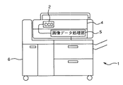
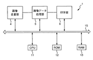
図1及び図2は、それぞれ、本発明の実施の形態1に係る複写機を概略的に示す図、及び、該複写機の基本的な構成を示すブロック図である。この複写機1は、基本的な構成として、光学系を用いて原稿を読み取り画像データを取得する画像走査部4と、画像データに対して文字認識処理を含む各種の処理を施す画像データ処理部5と、画像データに基づき印刷を実行する印字部6とを有している。図2から分かるように、これらの構成要素は、データバス15を介して、複写機1に組み込まれる各種の構成要素の制御を行なうCPU11,該CPU11の制御プログラムを記憶するROM12、及び、CPU11が制御のために実行するプログラムやデータを一時的に格納するRAM13と接続されている。
【0011】
この複写機1では、まず、画像走査部4において、原稿台上の原稿がCCD2により光学的に読み取られ、光電変換される。CCD2としては、R(赤),G(緑),B(青)の各色成分に対応する3ラインのリニアCCDが用いられる。このリニアCCDは、原稿台上の原稿に光を照射する場合に、その反射光からR,G,Bの各色光を1回の走査で取得可能であり、各色光を電気信号(アナログ画像データ)に変換することができる。上記画像走査部4により取得されたアナログ画像データは、画像データ処理部5へ入力され、印字部6に適した出力形式となるように処理される。印字部6では、画像データ処理部5から出力された画像データに基づき、印刷プリントが作成される。この間の各構成要素の動作は、上記ROM12に記録されたプログラムが、RAM13に格納された上で、順次、CPU12に読み出されることにより実行される。
【0012】
画像データ処理部5には、原稿に印刷された所定の形状及び寸法を備えたパターンを検出するパターン検出処理部が組み込まれている。図3は、画像データ処理部5に組み込まれるパターン検出処理部の構成をあらわすブロック図である。このパターン検出処理部20は、デジタル化された画像データが入力される画像入力部21と、画像データを低解像度化する低解像度化処理部22と、低解像度化された画像データを構成する各画素の濃度値を判断した上でラベリング(二値化)する二値化処理部23とを有している。
【0013】
画像入力部21に入力される画像データは、R(赤),G(緑),B(青)の各色がそれぞれ8ビット(256階調)の濃度値を有するデータである。この画像入力部21では、必要に応じて、画像データに対して、解像度変換,変倍等の前処理が加えられる。上記二値化処理部22は、画像データを構成する各画素の所定の色(パターンの色)についての濃度値が、予め設定された「参照濃度範囲」に含まれるか否かを判断し、該参照濃度範囲内の濃度値を有する画素をオン画素に設定するように、二値化処理を行なう。なお、「オン画素」とは、二値画像データにおける値1を有する画素、すなわち点の存在する画素をあらわし、以下の説明でも同様である。その後、画像データは、低解像度化処理部23に入力され、間引きされることにより、後のエレメント認識処理の処理対象となる低解像度のデータに変換される。低解像度化された画像データは、その後、所定のメモリ(例えばRAM13)に一旦格納される。
【0014】
また、図3から分かるように、パターン検出処理部20は、画像データに含まれる特定パターンの一部であるエレメントを認識するエレメント認識処理部24と、複数のエレメントから構成されるパターンの判定を行なうパターン判定処理部25と、判定結果に得点を設定する得点設定処理部26とを有している。
エレメント認識処理部24は、RAM13に格納される画像データを読み出し、その画像データ中のエレメントを認識する。この「エレメント」は、パターンの一部を構成する部分画像であり、中抜きの形状,寸法及び色を備えた画像である。エレメント認識処理の結果は、再度、RAM13に格納される。パターン判定処理部25は、RAM13に格納された複数のエレメントの配置に基づき、それらのエレメントから特定のパターンが構成されるか否かの判定を行なう。そして、得点設定処理部26は、パターン判定処理部25による判定結果に対して、それに応じた得点を設定する。
【0015】
図4は、上記の構成を備えたパターン検出処理部20によるパターン検出処理のフローチャートである。このパターン検出処理では、まず、画像入力部21を介して入力されたカラー画像データをパターンの色に関し二値化する(S11)。次に、二値画像データをより低解像度の画像データに変換する(S12)。更に、低解像度化された二値画像データの全体を、エレメントが納まるサイズ(m×n画素ブロック)のフィルタで順次走査し、該画像データ中のエレメントを認識する(S13)。このエレメント認識処理については、図10を参照して詳しく後述する。続いて、二値画像データを、特定のパターンが納まるサイズのフィルタで走査し、認識されるエレメントの配置に基づき、パターンを判定する(S14)。そして、取得されたパターン判定結果を評価し、それに応じた得点を設定する(S15)。以上で、パターン検出処理を終了する。
【0016】
図5は、パターン検出処理部20内のエレメント認識処理部24の構成をあらわすブロック図である。このエレメント認識処理部24は、画像データ中の認識対象を所定の条件に基づき評価して、その条件を満たす認識対象を「エレメント候補」と判定するエレメント候補判定部31と、該エレメント候補と判定された認識対象のサイズを検出するエレメント候補サイズ検出部32と、上記認識対象を含む画素ブロック領域内の着目画素及びその周辺の所定範囲にある画素からなる参照ブロックに存在するオフ画素を検出するオフ画素検出部33と、これら各構成要素による判定及び検出結果を受け、最終的なエレメント判定を行なう最終エレメント判定部34とを有している。この実施の形態では、エレメント認識処理部24とRAM13との間で行なわれるデータの読出し又は格納が、メモリ制御部18を介して制御される。
なお、「着目画素」とは、エレメント認識処理に際して、エレメントが納まるサイズ(m×n画素ブロック)のフィルタで画像データ中の各画素ブロック領域を順次走査する場合に、各画素ブロック領域の中心若しくはその近傍にある基準の画素をあらわし、また、「オフ画素」とは、二値画像データにおいて値0を有する画素、すなわち点のない画素をあらわす。これらは、以下の説明でも同様である。
【0017】
メモリ制御部18は、エレメント認識処理に際して、二値画像データが格納されているRAM13上のアドレスを算出し、該RAM13から二値画像データ中の画素ブロック領域を順次読み出す。この画素ブロック領域は、着目画素を中心にしたm×n個の画素からなる矩形のブロック領域であり、そのサイズは、処理解像度や理想的なエレメントのサイズに関係して決定される。メモリ制御部18により読み出された画素ブロック領域は、エレメント候補判定部31及びオフ画素検出部33へ入力される。
【0018】
エレメント候補判定部31は、入力された画素ブロック領域内の認識対象を所定の条件に基づき評価して、その条件を満たす認識対象を「エレメント候補」と判定する。上記所定の条件は、▲1▼画素ブロック領域の最外ラインを構成する画素が全てオフ画素であること、また、▲2▼画素ブロック領域内の着目画素を中心とした所定領域に含まれるオン画素の数が、規定の範囲内に納まることである。
【0019】
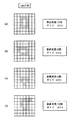
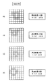
例えば、図6に示すように、理想的なエレメントは、4×4画素ブロック領域内で、中央にある2×2画素及び頂点をなす4画素を除き、オン画素が上下及び左右に対称に配置されてなる中抜き円形の画像である。図6において、ハッチングを施した画素はオン画素である。この理想的なエレメントについて、7×7画素ブロック領域におけるエレメント候補判定を行なう。この場合に、上記条件▲1▼及び▲2▼に対応する条件として、7×7画素ブロック領域の最外ラインを構成する画素が全てオフ画素であること、及び、7×7画素ブロック領域内の着目画素を中心とした5×5画素ブロック領域に含まれるオン画素の数が6〜10に納まることを設定する。このような条件に基づき評価される結果、図7に示すような各種の7×7画素ブロック領域に含まれる認識対象が、共に、エレメント候補と判定される。これらの認識対象は、図6に示すような理想的なエレメントとは形状又はサイズに関して異なるものの、上記条件▲1▼及び▲2▼を満たすので、エレメント候補と判定される。これに対して、図8に示すような各種の7×7画素ブロック領域に含まれる認識対象は、上記条件▲1▼及び▲2▼の少なくとも一方を満たさず、エレメント候補と判定されない。
エレメント候補判定部31によりエレメント候補と判定された認識対象を含む画素ブロック領域は、随時、エレメント候補サイズ検出部32及び最終エレメント判定部34へ入力される。
【0020】
エレメント候補サイズ検出部32は、エレメント候補判定部31によりエレメント候補と判定された認識対象を含む画素ブロック領域を受け、認識対象のサイズを検出する。このとき、認識対象のサイズは、認識対象が納まる矩形の画素ブロックのサイズ(すなわちm×n画素ブロック)を用いてあらわされる。例えば、認識対象が、図6に示すような理想的なエレメントと同一である場合には、そのサイズが「4×4画素ブロック」とあらわされる。このエレメント候補サイズ検出部32による検出結果は、随時、オフ画素検出部33へ入力される。
【0021】
オフ画素検出部33は、エレメント候補サイズ検出部32による検出結果を受け、この検出結果に基づき、まず、RAM13からメモリ制御部18を介して入力された画素ブロック領域から、認識対象のサイズに対応するサイズを備えた画素ブロックを抽出する。続いて、上記抽出された画素ブロックにおいて、それに含まれる着目画素及びその周辺の所定範囲にある画素からなる参照ブロックを設定し、該参照ブロック内のオフ画素を検出する。そして、参照ブロック内にオフ画素が検出された場合に、画素ブロックに含まれる認識対象を中抜き形状を備えたエレメントと判定する。
【0022】
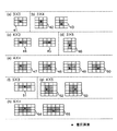
図9の(a)〜(h)には、このオフ画素検出処理に際して、認識対象のサイズに対応する画素ブロックとして抽出された各種の画素ブロックにおける参照ブロックの設定例を示す。なお、図示された各種の画素ブロックにおいて、星形のマークが付された画素は着目画素をあらわし、斜線が付された領域は参照ブロックをあらわす。
図9の(a)に示す3×3画素ブロック41では、着目画素が中心の画素であり、該中心の画素のみが参照ブロックに設定される。この着目画素がオフ画素である場合には、認識対象が所定の形状を有するエレメントと判定される。また、図9の(b)に示す3×4画素ブロック42,43では、着目画素がブロック内部にある2画素のいずれか一方であり、その着目画素とそれに隣接するブロック内部の1画素とにより構成される参照ブロックが設定されている。着目画素の位置が互いに異なる3×4画素ブロック42,43において、参照ブロックはブロック内部の同一領域に設定される。これは、図9の(c)に示す4×3画素ブロック44,45についても同様である。
【0023】
更に、図9の(d)に示す3×5画素ブロック46では、着目画素が中心の画素であり、該中心の画素とそれに隣接するブロック内部の2画素とにより構成される参照ブロックが設定されている。また、更に、図9の(e)に示す4×4画素ブロック47,48,49,50では、着目画素がブロック内部にある4画素のうちのいずれか1つであり、その着目画素とそれに隣接するブロック内部の3画素とから構成される参照ブロックが設定されている。
【0024】
また、図9の(f)に示す5×3画素ブロック51では、図9の(d)に示す3×5画素ブロック46と同様に、着目画素が中心の画素であり、該中心の画素とそれに隣接するブロック内部の2画素とにより構成される参照ブロックが設定されている。更に、図9の(g)に示す4×5画素ブロック52,53では、着目画素がブロック内部にある中心近傍の2画素のいずれか一方であり、その着目画素とそれに隣接するブロック内部の5画素とから構成される参照ブロックが設定されている。これは、図9の(h)に示す5×4画素ブロックについても同様である。
【0025】
このように、上記参照ブロックのサイズは、抽出される画素ブロックのサイズ、つまり、上記エレメント候補判定部31によりエレメント候補と判定された認識対象のサイズに対応して可変である。すなわち、各種の処理解像度やエレメントのサイズについて対応可能である。
オフ画素検出部33による検出結果は、随時、最終エレメント判定部34へ送られる。
【0026】
最終エレメント判定部34は、エレメント候補判定部31からの判定結果及びオフ画素検出部33からの検出結果を受け、これに基づき、最終的に、その画素ブロック領域に含まれる認識対象をエレメントと判定する。この判定結果は、メモリ制御部18を介して、RAM13に送られ格納される。
【0027】
以上の処理を経て、各種条件の全て満たすことができない認識対象が排除される。これにより、図6に示すような理想的なエレメントに一層適合した認識対象を選別することができ、特に中抜きの形状を備えたエレメントを高精度に認識することができる。また、この実施の形態では、画像データを低解像度化した上で前述したようなエレメント認識処理が施されるため、処理の高速化,使用メモリの削減を実現することができる。更に、この実施の形態では、エレメントが略中抜き円形の画像であるため、上下及び左右に対称な形状として、比較的簡単な条件により、認識すべき形状を特定することができる。
【0028】
図10は、エレメント認識処理(図4のS13)についてのフローチャートである。この処理では、例えば図6に示す理想的なエレメントが納まるサイズのフィルタで画像データが走査され、フィルタ内の各画素ブロック領域について、前述したような判定条件を満たしているか否かが判断される。なお、このフローチャートは、7×7画素ブロック領域に対応するフィルタを用いた場合について説明するものである。
本処理に入ると、まず、低解像度化された後に格納された二値画像データを読み出す(S21)。次に、フィルタの走査開始位置を決定する。すなわち、フィルタのY方向座標を画像データの上端に位置するように設定し(S22)、フィルタのX方向座標を画像データの左端に位置するように設定する(S23)。
【0029】
走査を開始すると、まず、フィルタ内の7×7画素ブロック領域について、7×7画素ブロック領域の最外ラインが全てオフ画素であるか否かを判断する(S24)。判断の結果、全てオフ画素でない場合には、画素ブロック領域内の認識対象がエレメントでないと判断し、エレメントフラグを「オフ」にセットする(S29)。その後、S30へ進む。他方、全てオフ画素である場合、S25へ進む。S25では、5×5画素ブロック領域内のオン画素数が6〜10であるか否かを判断する。その結果、6〜10でない場合には、エレメントフラグを「オフ」にセットした後(S29)、S30へ進む。他方、6〜10である場合、S26へ進む。
【0030】
S26では、上記7×7画素ブロック領域に含まれるエレメント候補のサイズを調べる。S27では、エレメント候補のサイズに対応する5×5画素ブロック内にて設定された参照ブロック内に、オフ画素が存在するか否かを判断する。その結果、オフ画素が存在しない場合には、エレメントフラグを「オフ」にセットした後(S29)、S30へ進む。他方、オフ画素が存在する場合、S28へ進む。S28では、S24,S25及びS27の条件の全てを満たしていることから、画素ブロック領域内の認識対象が所定の形状を備えたエレメントであると判定し、エレメントフラグを「オン」にセットする。その後、S30へ進む。
【0031】
S30では、認識対象とする7×7画素ブロック領域が、X方向の最終の画素ブロック領域であるか否かを判断する。この結果、最終の画素ブロック領域でない場合には、フィルタをX方向へ1画素分だけずらした上で(S31)、S24へ戻り、それ以降のステップを行なう。他方、最終の画素ブロック領域である場合には、S32へ進み、認識対象とする7×7画素ブロック領域が、Y方向の最終の画素ブロック領域であるか否かを判断する。その結果、最終の画素ブロック領域でない場合には、フィルタをY方向へ1画素分だけずらした上で(S33)、S23へ戻り、それ以降のステップを行なう。他方、最終の画素ブロック領域である場合には、エレメント認識処理を終了し、メインルーチンへリターンする。
【0032】
このようなS21〜S33のエレメント認識処理は、複写機1に組み込まれたオペレーティングプログラムに基づいて実行されるものであり、この実施の形態では、上記プログラムが、複写機1内のROM12(図2参照)に格納されている。また、これに限定されることなく、このようなプログラムは、例えばフロッピーディスク,CD−ROM等の外部記録媒体にファイル形式で格納されてもよい。
【0033】
なお、本発明は、例示された実施の形態に限定されるものでなく、本発明の要旨を逸脱しない範囲において、種々の改良及び設計上の変更が可能であることは言うまでもない。例えば、図5を参照して説明したエレメント認識処理部24の各構成要素をハードウェア化してもよい。この場合には、RAM13から各構成要素(エレメント候補判定部31,エレメント候補サイズ検出部32,オフ画素検出部33)へ画素ブロック領域が同時に入力され、その後、エレメント候補判定部31及びオフ画素検出部33による判定及び検出結果が、個々に、最終エレメント判定部34へ入力される。最終エレメント判定部34では、入力された判定及び検出結果が総合的に評価され、認識対象が所定の形状を備えたエレメントであるか否かが判定される。
【0034】
【発明の効果】
以上の説明から明らかなように、本願の請求項1に係る発明によれば、画像に含まれる特定のパターンの検出を行なうパターン検出装置において、画像データを二値化する二値化手段と、二値化処理手段により二値化された画像データに含まれる、上記特定のパターンの一部である中抜き形状を備えた部分画像を認識する部分画像認識手段とを有しており、上記部分画像認識手段は、上記部分画像が納まるサイズを備えた画像データ中の各ブロック領域を走査し、所定の条件に基づいて上記ブロック領域に含まれる認識対象を評価して上記部分画像の候補を検出し、上記部分画像の候補として検出された認識対象のサイズを検出し、上記認識対象のサイズに対応してサイズを可変的に設定した画素ブロック内において、着目画素及びその周辺の所定範囲にある画素からなる参照ブロックを定め、上記参照ブロック内に少なくとも1つのオフ画素が存在するという条件を満たす認識対象を部分画像と判定するため、理想的な部分画像に一層適合する認識対象を選別し、中抜き形状を備えた部分画像を高精度に認識することができ、上記参照ブロックのサイズが、上記画像データ中のブロック領域に含まれる認識対象のサイズに対応して可変であり、各種の処理解像度やエレメントのサイズについて対応可能である。
【0035】
また、本願の請求項2に係る発明によれば、上記認識対象のサイズは、認識対象が納まる矩形の画素ブロックのサイズとして検出される。
【0036】
更に、本願の請求項3に係る発明によれば、画像に含まれる特定のパターンの検出を行なうパターン検出方法において、画像データを二値化するステップと、上記二値化ステップにおいて二値化された画像データに含まれる、上記特定のパターンの一部である中抜き形状を備えた部分画像を認識する部分画像認識ステップとを有しており、上記部分画像認識ステップは、上記部分画像が納まるサイズを備えた画像データ中の各ブロック領域を走査する間に、所定の条件に基づいて上記ブロック領域に含まれる認識対象を評価して上記部分画像の候補を検出するサブステップと、上記部分画像の候補として検出された認識対象のサイズを検出するサブステップと、上記認識対象のサイズに対応してサイズを可変的に設定した画素ブロック内において、着目画素及びその周辺の所定範囲にある画素からなる参照ブロックを定めるサブステップと、上記参照ブロック内に少なくとも1つのオフ画素が存在するという条件を満たす認識対象を部分画像と判定するサブステップとを含む、ことを特徴としているため、理想的な部分画像に一層適合する認識対象を選別し、中抜き形状を備えた部分画像を高精度に認識することができる。
【0037】
また、更に、本願の請求項4に係る発明によれば、画像に含まれる特定のパターンの検出を行なう際に用いられるパターン検出プログラムを記録したコンピュータ読取り可能な記録媒体であって、該パターン検出プログラムが、画像データを二値化するステップと、上記二値化ステップにおいて二値化された画像データに含まれる、上記特定のパターンの一部である中抜き形状を備えた部分画像を認識する部分画像認識ステップとを有しており、上記部分画像認識ステップは、上記部分画像が納まるサイズを備えた画像データ中の各ブロック領域を走査する間に、所定の条件に基づいて上記ブロック領域に含まれる認識対象を評価して上記部分画像の候補を検出するサブステップと、上記部分画像の候補として検出された認識対象のサイズを検出するサブステップと、上記認識対象のサイズに対応してサイズを可変的に設定した画素ブロック内において、着目画素及びその周辺の所定範囲にある画素からなる参照ブロックを定めるサブステップと、上記参照ブロック内に少なくとも1つのオフ画素が存在するという条件を満たす認識対象を部分画像と判定するサブステップとを含む、ことを特徴としているため、理想的な部分画像に一層適合する認識対象を選別し、中抜き形状を備えた部分画像を高精度に認識することができる。
【図面の簡単な説明】
【図1】 本発明の実施の形態に係る複写機を概略的に示す図である。
【図2】 上記複写機の基本構成をあらわすブロック図である。
【図3】 図2の画像データ処理部内のパターン検出処理部の構成をあらわすブロック図である。
【図4】 パターン検出処理のフローチャートである。
【図5】 上記パターン検出処理部内のエレメント認識処理部の構成をあらわすブロック図である。
【図6】 理想的なエレメントを構成する画素の配置を示す図である。
【図7】 エレメント候補と判定される認識対象を含む各種の7×7画素ブロック領域を示す図である。
【図8】 エレメント候補と判定されない認識対象を含む各種の7×7画素ブロック領域を示す図である。
【図9】 各種サイズのエレメント候補を含む画素ブロックにおける参照ブロックの設定例を示す図である。
【図10】 エレメント認識処理についてのフローチャートである。
【符号の説明】
1…複写機
5…画像データ処理部
13…RAM
18…メモリ制御部
20…パターン検出処理部
21…画像入力部
22…二値化処理部
23…低解像度化処理部
24…エレメント認識処理部
25…パターン判定処理部
26…得点設定処理部
31…エレメント判定部
32…エレメント候補サイズ検出部
33…オフ画素検出部
34…最終エレメント判定部[0001]
BACKGROUND OF THE INVENTION
The present invention relates to a pattern detection apparatus and method for detecting a specific pattern included in an image.
[0002]
[Prior art]
Conventionally, for example, in one of the data processing performed in a copying machine, the acquired image data is stored in the image memory as binary data or multi-value data, and each pixel of the reference pattern stored in the memory in advance is stored with this data. There is known a pattern matching process for detecting a specific pattern included in an image, recognizing a shape, and the like by collating with the above data.
[0003]
By the way, in recent years, as an input device for scanning and an output device for outputting image data as a print print, those capable of processing image data having a large amount of information such as high resolution data at high speed are becoming widespread. In order to realize data processing including pattern matching processing in real time in cooperation with these input / output devices, there is a problem that the hardware configuration is not limited. In order to solve this problem, there is a need for a pattern detection apparatus that can detect a specific pattern at high speed and that has a simple configuration.
[0004]
[Problems to be solved by the invention]
As such a pattern detection device, for example, after the binary data is reduced in resolution, (1) an ON pixel (that is, a dot is present in a rectangular block region of m × n pixels around the target pixel). The number of existing pixels) falls within a predetermined range, and (2) a predetermined shape and size as a part of a specific pattern are provided based on the condition that there are no ON pixels in the predetermined area around the block area. Those that recognize partial images are known. However, in this pattern detection device, it is not possible to sufficiently specify a partial image having a hollow shape in particular, and other images (for example, a circular image with a solid interior or the like) There has been a problem of erroneously detecting a quadrangle or triangular pixel image having a size of 1).
[0005]
The present invention has been made in view of the above technical problem, and can detect a specific pattern with high accuracy and high speed, and has a simple configuration and a specific pattern using the pattern detection device. An object is to provide a detection method.
[0006]
[Means for Solving the Problems]
The invention according to
[0007]
The invention according to claim 2 of the present application is the invention according to
[0008]
Furthermore, the invention according to claim 3 of the present application is a pattern detection method for detecting a specific pattern included in an image, the step of binarizing image data, and the image binarized in the binarization step. A partial image recognition step for recognizing a partial image having a hollow shape that is part of the specific pattern included in the data, and the partial image recognition stepIs, While scanning each block area in the image data having a size that can accommodate the partial image,A sub-step of detecting a recognition target included in the block region based on a predetermined condition and detecting a candidate of the partial image; a sub-step of detecting a size of the recognition target detected as the partial image candidate; In the pixel block in which the size is variably set corresponding to the size of the recognition target,Reference block consisting of a pixel of interest and pixels in a predetermined range around itSub-steps to determine,In the above reference blockA recognition target that satisfies the condition that at least one off pixel exists is determined as a partial image.Including sub-steps,It is characterized by that.
[0009]
Furthermore, the invention according to claim 4 of the present application is a computer-readable recording medium on which a pattern detection program used for detecting a specific pattern included in an image is recorded, and the pattern detection program , A step of binarizing image data, and a partial image for recognizing a partial image having a hollow shape that is part of the specific pattern included in the image data binarized in the binarization step A partial image recognition step.Is, While scanning each block area in the image data having a size that can accommodate the partial image,A sub-step of detecting a recognition target included in the block region based on a predetermined condition and detecting a candidate of the partial image; a sub-step of detecting a size of the recognition target detected as the partial image candidate; In the pixel block in which the size is variably set corresponding to the size of the recognition target,Reference block consisting of a pixel of interest and pixels in a predetermined range around itSub-steps to determine,In the above reference blockA recognition target that satisfies the condition that at least one off pixel exists is determined as a partial image.Including sub-steps,It is characterized by that.
[0010]
DETAILED DESCRIPTION OF THE INVENTION
Hereinafter, embodiments of the present invention will be described with reference to the accompanying drawings.
FIG. 1 and FIG. 2 are a diagram schematically showing a copier according to
[0011]
In this
[0012]
The image
[0013]
The image data input to the
[0014]
As can be seen from FIG. 3, the pattern
The element
[0015]
FIG. 4 is a flowchart of pattern detection processing by the pattern
[0016]
FIG. 5 is a block diagram showing the configuration of the element
Note that the “target pixel” refers to the center of each pixel block area or the center of each pixel block area when the pixel block area in the image data is sequentially scanned by a filter of a size (m × n pixel block) in which the element is accommodated in the element recognition process. A reference pixel in the vicinity thereof is represented, and the “off pixel” represents a pixel having a value of 0 in the binary image data, that is, a pixel having no point. The same applies to the following description.
[0017]
During the element recognition process, the memory control unit 18 calculates an address on the
[0018]
The element
[0019]
For example, as shown in FIG. 6, ideal elements are arranged symmetrically on the top and bottom and left and right, except for 2 × 2 pixels at the center and 4 pixels at the top in the 4 × 4 pixel block area. This is a hollow circular image. In FIG. 6, the hatched pixels are on pixels. With respect to this ideal element, element candidate determination in the 7 × 7 pixel block region is performed. In this case, as conditions corresponding to the above conditions (1) and (2), all the pixels constituting the outermost line of the 7 × 7 pixel block area are off pixels, and within the 7 × 7 pixel block area It is set that the number of ON pixels included in the 5 × 5 pixel block region centering on the target pixel is within the range of 6 to 10. As a result of evaluation based on such conditions, recognition targets included in various 7 × 7 pixel block areas as shown in FIG. 7 are both determined as element candidates. Although these recognition targets differ from the ideal elements as shown in FIG. 6 in terms of shape or size, they satisfy the above conditions (1) and (2), and are thus determined as element candidates. On the other hand, recognition targets included in various 7 × 7 pixel block areas as shown in FIG. 8 do not satisfy at least one of the above conditions (1) and (2), and are not determined as element candidates.
A pixel block region including a recognition target determined as an element candidate by the element
[0020]
The element candidate
[0021]
The off-
[0022]
FIGS. 9A to 9H show setting examples of reference blocks in various pixel blocks extracted as pixel blocks corresponding to the size of the recognition target in the off-pixel detection process. In the various pixel blocks shown in the figure, a pixel with a star mark represents a target pixel, and a hatched area represents a reference block.
In the 3 × 3
[0023]
Further, in the 3 × 5
[0024]
Further, in the 5 × 3
[0025]
Thus, the size of the reference block is variable corresponding to the size of the extracted pixel block, that is, the size of the recognition target determined as an element candidate by the element
The detection result by the off-
[0026]
The final
[0027]
Through the above processing, recognition targets that cannot satisfy all of the various conditions are eliminated. This makes it possible to select a recognition target that is more suitable for an ideal element as shown in FIG. 6, and particularly to recognize an element having a hollow shape with high accuracy. Further, in this embodiment, since the element recognition processing as described above is performed after the resolution of the image data is reduced, the processing speed can be increased and the memory used can be reduced. Furthermore, in this embodiment, since the element is a substantially hollow circular image, the shape to be recognized can be specified under relatively simple conditions as a shape that is vertically and horizontally symmetrical.
[0028]
FIG. 10 is a flowchart of the element recognition process (S13 in FIG. 4). In this process, for example, image data is scanned with a filter of a size that accommodates the ideal element shown in FIG. 6, and it is determined whether each pixel block region in the filter satisfies the determination condition as described above. . This flowchart describes the case where a filter corresponding to a 7 × 7 pixel block region is used.
In this process, first, binary image data stored after the resolution is reduced is read (S21). Next, the scanning start position of the filter is determined. That is, the Y-direction coordinate of the filter is set to be positioned at the upper end of the image data (S22), and the X-direction coordinate of the filter is set to be positioned at the left end of the image data (S23).
[0029]
When scanning is started, it is first determined whether or not all the outermost lines of the 7 × 7 pixel block region are off pixels in the 7 × 7 pixel block region in the filter (S24). If it is determined that all pixels are not off, it is determined that the recognition target in the pixel block area is not an element, and the element flag is set to “off” (S29). Then, it progresses to S30. On the other hand, if all are off pixels, the process proceeds to S25. In S25, it is determined whether or not the number of ON pixels in the 5 × 5 pixel block region is 6 to 10. As a result, if it is not 6 to 10, the element flag is set to “off” (S29), and the process proceeds to S30. On the other hand, if it is 6 to 10, the process proceeds to S26.
[0030]
In S26, the size of the element candidate included in the 7 × 7 pixel block area is checked. In S27, it is determined whether or not an off pixel exists in the reference block set in the 5 × 5 pixel block corresponding to the size of the element candidate. As a result, if there is no off pixel, the element flag is set to “off” (S29), and the process proceeds to S30. On the other hand, if there is an off pixel, the process proceeds to S28. In S28, since all the conditions of S24, S25, and S27 are satisfied, it is determined that the recognition target in the pixel block region is an element having a predetermined shape, and the element flag is set to “ON”. Then, it progresses to S30.
[0031]
In S30, it is determined whether or not the 7 × 7 pixel block region to be recognized is the final pixel block region in the X direction. As a result, if it is not the final pixel block region, the filter is shifted by one pixel in the X direction (S31), and the process returns to S24 and the subsequent steps are performed. On the other hand, if it is the final pixel block region, the process proceeds to S32, and it is determined whether or not the 7 × 7 pixel block region to be recognized is the final pixel block region in the Y direction. As a result, if it is not the final pixel block region, the filter is shifted by one pixel in the Y direction (S33), the process returns to S23, and the subsequent steps are performed. On the other hand, if it is the final pixel block area, the element recognition process is terminated and the process returns to the main routine.
[0032]
Such element recognition processing in S21 to S33 is executed based on an operating program incorporated in the copying
[0033]
Note that the present invention is not limited to the illustrated embodiments, and it goes without saying that various improvements and design changes are possible without departing from the scope of the present invention. For example, each component of the element
[0034]
【The invention's effect】
As is clear from the above description, according to the invention according to
[0035]
According to the invention of claim 2 of the present application, the aboveThe size of the recognition target is detected as the size of a rectangular pixel block that contains the recognition target..
[0036]
Furthermore, according to the invention according to claim 3 of the present application, in the pattern detection method for detecting a specific pattern included in an image, the image data is binarized in the binarization step and the binarization step. A partial image recognition step for recognizing a partial image having a hollow shape that is a part of the specific pattern included in the image data, and the partial image recognition stepIs, While scanning each block area in the image data having a size that can accommodate the partial image,A sub-step of detecting a recognition target included in the block region based on a predetermined condition and detecting a candidate of the partial image; a sub-step of detecting a size of the recognition target detected as the partial image candidate; In the pixel block in which the size is variably set corresponding to the size of the recognition target,Reference block consisting of a pixel of interest and pixels in a predetermined range around itSub-steps to determine,In the above reference blockA recognition target that satisfies the condition that at least one off pixel exists is determined as a partial image.Including sub-steps,Therefore, it is possible to select a recognition object that is more suitable for an ideal partial image, and to recognize a partial image having a hollow shape with high accuracy.
[0037]
Furthermore, according to the invention according to claim 4 of the present application, there is provided a computer-readable recording medium recording a pattern detection program used when detecting a specific pattern included in an image, the pattern detection A program recognizes a step of binarizing image data and a partial image having a hollow shape that is a part of the specific pattern included in the image data binarized in the binarization step. A partial image recognition step, and the partial image recognition stepIs, While scanning each block area in the image data having a size that can accommodate the partial image,A sub-step of detecting a recognition target included in the block region based on a predetermined condition and detecting a candidate of the partial image; a sub-step of detecting a size of the recognition target detected as the partial image candidate; In the pixel block in which the size is variably set corresponding to the size of the recognition target,Reference block consisting of a pixel of interest and pixels in a predetermined range around itSub-steps to determine,In the above reference blockA recognition target that satisfies the condition that at least one off pixel exists is determined as a partial image.Including sub-steps,Therefore, it is possible to select a recognition object that is more suitable for an ideal partial image, and to recognize a partial image having a hollow shape with high accuracy.
[Brief description of the drawings]
FIG. 1 is a diagram schematically showing a copying machine according to an embodiment of the present invention.
FIG. 2 is a block diagram showing a basic configuration of the copying machine.
3 is a block diagram showing a configuration of a pattern detection processing unit in the image data processing unit of FIG. 2;
FIG. 4 is a flowchart of pattern detection processing.
FIG. 5 is a block diagram showing a configuration of an element recognition processing unit in the pattern detection processing unit.
FIG. 6 is a diagram illustrating an arrangement of pixels constituting an ideal element.
FIG. 7 is a diagram showing various 7 × 7 pixel block areas including a recognition target determined as an element candidate.
FIG. 8 is a diagram illustrating various 7 × 7 pixel block regions including recognition targets that are not determined as element candidates.
FIG. 9 is a diagram illustrating a setting example of a reference block in a pixel block including element candidates of various sizes.
FIG. 10 is a flowchart for element recognition processing;
[Explanation of symbols]
1 ... Copier
5. Image data processing unit
13 ... RAM
18 ... Memory control unit
20 ... pattern detection processing unit
21. Image input unit
22: Binarization processing unit
23. Resolution reduction processing unit
24 ... Element recognition processing unit
25. Pattern determination processing unit
26 ... Score setting processing section
31 ... Element determination part
32 ... Element candidate size detection unit
33: Off-pixel detection unit
34 ... Final element determination section
Claims (4)
画像データを二値化する二値化手段と、
二値化処理手段により二値化された画像データに含まれる、上記特定のパターンの一部である中抜き形状を備えた部分画像を認識する部分画像認識手段とを有しており、
上記部分画像認識手段は、
上記部分画像が納まるサイズを備えた画像データ中の各ブロック領域を走査し、
所定の条件に基づいて上記ブロック領域に含まれる認識対象を評価して上記部分画像の候補を検出し、
上記部分画像の候補として検出された認識対象のサイズを検出し、
上記認識対象のサイズに対応してサイズを可変的に設定した画素ブロック内において、着目画素及びその周辺の所定範囲にある画素からなる参照ブロックを定め、
上記参照ブロック内に少なくとも1つのオフ画素が存在するという条件を満たす認識対象を部分画像と判定することを特徴とするパターン検出装置。In a pattern detection apparatus for detecting a specific pattern included in an image,
Binarization means for binarizing image data;
Partial image recognition means for recognizing a partial image having a hollow shape that is part of the specific pattern included in the image data binarized by the binarization processing means,
The partial image recognition means,
It scans each block region in the image data having a size of the partial image fits,
Evaluating a recognition target included in the block area based on a predetermined condition to detect a candidate for the partial image;
Detect the size of the recognition target detected as a candidate for the partial image,
In a pixel block whose size is variably set corresponding to the size of the recognition target, a reference block including a pixel of interest and pixels in a predetermined range around it is determined .
A pattern detection apparatus that determines a recognition target that satisfies a condition that at least one off pixel exists in the reference block as a partial image.
画像データを二値化するステップと、
上記二値化ステップにおいて二値化された画像データに含まれる、上記特定のパターンの一部である中抜き形状を備えた部分画像を認識する部分画像認識ステップとを有しており、
上記部分画像認識ステップは、
上記部分画像が納まるサイズを備えた画像データ中の各ブロック領域を走査する間に、
所定の条件に基づいて上記ブロック領域に含まれる認識対象を評価して上記部分画像の候補を検出するサブステップと、
上記部分画像の候補として検出された認識対象のサイズを検出するサブステップと、
上記認識対象のサイズに対応してサイズを可変的に設定した画素ブロック内において、着目画素及びその周辺の所定範囲にある画素からなる参照ブロックを定めるサブステップと、
上記参照ブロック内に少なくとも1つのオフ画素が存在するという条件を満たす認識対象を部分画像と判定するサブステップとを含む、ことを特徴とするパターン検出方法。In a pattern detection method for detecting a specific pattern included in an image,
Binarizing image data; and
A partial image recognition step for recognizing a partial image having a hollow shape that is a part of the specific pattern included in the image data binarized in the binarization step,
The partial image recognition step includes
While scanning each block area in the image data having a size that can accommodate the partial image,
A sub-step of evaluating a recognition target included in the block region based on a predetermined condition to detect a candidate for the partial image;
A sub-step of detecting a size of a recognition target detected as a candidate for the partial image;
A sub-step for defining a reference block including a pixel of interest and pixels in a predetermined range around the pixel in a pixel block whose size is variably set corresponding to the size of the recognition target ;
And a sub-step of determining, as a partial image, a recognition target that satisfies a condition that at least one off pixel exists in the reference block .
画像データを二値化するステップと、
上記二値化ステップにおいて二値化された画像データに含まれる、上記特定のパターンの一部である中抜き形状を備えた部分画像を認識する部分画像認識ステップとを有しており、
上記部分画像認識ステップは、
上記部分画像が納まるサイズを備えた画像データ中の各ブロック領域を走査する間に、
所定の条件に基づいて上記ブロック領域に含まれる認識対象を評価して上記部分画像の候補を検出するサブステップと、
上記部分画像の候補として検出された認識対象のサイズを検出するサブステップと、
上記認識対象のサイズに対応してサイズを可変的に設定した画素ブロック内において、着目画素及びその周辺の所定範囲にある画素からなる参照ブロックを定めるサブステップと、
上記参照ブロック内に少なくとも1つのオフ画素が存在するという条件を満たす認識対象を部分画像と判定するサブステップとを含む、ことを特徴とするコンピュータ読み取り可能な記録媒体。A computer-readable recording medium recording a pattern detection program used when detecting a specific pattern included in an image, the pattern detection program comprising:
Binarizing image data; and
A partial image recognition step for recognizing a partial image having a hollow shape that is a part of the specific pattern included in the image data binarized in the binarization step,
The partial image recognition step includes
While scanning each block area in the image data having a size that can accommodate the partial image,
A sub-step of evaluating a recognition target included in the block region based on a predetermined condition to detect a candidate for the partial image;
A sub-step of detecting a size of a recognition target detected as a candidate for the partial image;
A sub-step for defining a reference block including a pixel of interest and pixels in a predetermined range around the pixel in a pixel block whose size is variably set corresponding to the size of the recognition target ;
A computer-readable recording medium comprising: a sub-step of determining a recognition target satisfying a condition that at least one off pixel exists in the reference block as a partial image.
Priority Applications (3)
| Application Number | Priority Date | Filing Date | Title |
|---|---|---|---|
| JP2000125947A JP4206604B2 (en) | 2000-04-26 | 2000-04-26 | Pattern detection apparatus and method |
| US09/841,039 US7123768B2 (en) | 2000-04-26 | 2001-04-25 | Apparatus and method for detecting a pattern |
| US10/976,002 US7263228B2 (en) | 2000-04-26 | 2004-10-29 | Apparatus and method for detecting a pattern |
Applications Claiming Priority (1)
| Application Number | Priority Date | Filing Date | Title |
|---|---|---|---|
| JP2000125947A JP4206604B2 (en) | 2000-04-26 | 2000-04-26 | Pattern detection apparatus and method |
Publications (2)
| Publication Number | Publication Date |
|---|---|
| JP2001307089A JP2001307089A (en) | 2001-11-02 |
| JP4206604B2 true JP4206604B2 (en) | 2009-01-14 |
Family
ID=18635811
Family Applications (1)
| Application Number | Title | Priority Date | Filing Date |
|---|---|---|---|
| JP2000125947A Expired - Fee Related JP4206604B2 (en) | 2000-04-26 | 2000-04-26 | Pattern detection apparatus and method |
Country Status (1)
| Country | Link |
|---|---|
| JP (1) | JP4206604B2 (en) |
Families Citing this family (1)
| Publication number | Priority date | Publication date | Assignee | Title |
|---|---|---|---|---|
| JP4086829B2 (en) * | 2004-09-22 | 2008-05-14 | シャープ株式会社 | Image processing device |
-
2000
- 2000-04-26 JP JP2000125947A patent/JP4206604B2/en not_active Expired - Fee Related
Also Published As
| Publication number | Publication date |
|---|---|
| JP2001307089A (en) | 2001-11-02 |
Similar Documents
| Publication | Publication Date | Title |
|---|---|---|
| US7123768B2 (en) | Apparatus and method for detecting a pattern | |
| US5164996A (en) | Optical character recognition by detecting geo features | |
| JP4206604B2 (en) | Pattern detection apparatus and method | |
| JP3268552B2 (en) | Area extraction method, destination area extraction method, destination area extraction apparatus, and image processing apparatus | |
| JP4254008B2 (en) | Pattern detection apparatus and method | |
| JP2003115031A (en) | Image processor and its method | |
| JP4218179B2 (en) | Pattern detection apparatus and method | |
| JP3955467B2 (en) | Image processing program and image processing apparatus | |
| JPH08123901A (en) | Character extraction device and character recognition device using this device | |
| JPH08237404A (en) | Selection of optical character recognition mode | |
| JP4974367B2 (en) | Region dividing method and apparatus, and program | |
| JP2894111B2 (en) | Comprehensive judgment method of recognition result in optical type character recognition device | |
| JP3545227B2 (en) | Image processing method and apparatus, optical character reader | |
| JPS62251887A (en) | Character recognizing/graphic processing device | |
| JP2002259909A (en) | Character reader | |
| JP3660143B2 (en) | Seal image processing device | |
| JP4580520B2 (en) | Character recognition method and character recognition apparatus | |
| JP3244041B2 (en) | Image recognition method, image recognition device, and recording medium | |
| JPH08212296A (en) | Optical character reader | |
| JPH09319821A (en) | Method and device for bar code reading | |
| JP3747602B2 (en) | Image processing method and image processing apparatus | |
| JP2000187706A (en) | Paper sheets reader | |
| JP2007148719A (en) | Image processing device, method and program | |
| JPS63116282A (en) | Ocr with image input | |
| JP2002016799A (en) | Character detector, copying machine provided with it and character detection method |
Legal Events
| Date | Code | Title | Description |
|---|---|---|---|
| A711 | Notification of change in applicant |
Free format text: JAPANESE INTERMEDIATE CODE: A712 Effective date: 20050614 |
|
| A621 | Written request for application examination |
Free format text: JAPANESE INTERMEDIATE CODE: A621 Effective date: 20050920 |
|
| A521 | Written amendment |
Free format text: JAPANESE INTERMEDIATE CODE: A821 Effective date: 20051206 |
|
| RD02 | Notification of acceptance of power of attorney |
Free format text: JAPANESE INTERMEDIATE CODE: A7422 Effective date: 20051206 |
|
| A131 | Notification of reasons for refusal |
Free format text: JAPANESE INTERMEDIATE CODE: A131 Effective date: 20080701 |
|
| A521 | Written amendment |
Free format text: JAPANESE INTERMEDIATE CODE: A523 Effective date: 20080901 |
|
| TRDD | Decision of grant or rejection written | ||
| A01 | Written decision to grant a patent or to grant a registration (utility model) |
Free format text: JAPANESE INTERMEDIATE CODE: A01 Effective date: 20080924 |
|
| A01 | Written decision to grant a patent or to grant a registration (utility model) |
Free format text: JAPANESE INTERMEDIATE CODE: A01 |
|
| A61 | First payment of annual fees (during grant procedure) |
Free format text: JAPANESE INTERMEDIATE CODE: A61 Effective date: 20081007 |
|
| R150 | Certificate of patent or registration of utility model |
Free format text: JAPANESE INTERMEDIATE CODE: R150 |
|
| FPAY | Renewal fee payment (event date is renewal date of database) |
Free format text: PAYMENT UNTIL: 20111031 Year of fee payment: 3 |
|
| FPAY | Renewal fee payment (event date is renewal date of database) |
Free format text: PAYMENT UNTIL: 20121031 Year of fee payment: 4 |
|
| FPAY | Renewal fee payment (event date is renewal date of database) |
Free format text: PAYMENT UNTIL: 20121031 Year of fee payment: 4 |
|
| FPAY | Renewal fee payment (event date is renewal date of database) |
Free format text: PAYMENT UNTIL: 20131031 Year of fee payment: 5 |
|
| S111 | Request for change of ownership or part of ownership |
Free format text: JAPANESE INTERMEDIATE CODE: R313111 |
|
| R350 | Written notification of registration of transfer |
Free format text: JAPANESE INTERMEDIATE CODE: R350 |
|
| LAPS | Cancellation because of no payment of annual fees |