JP4205706B2 - Method for forming groove wall in soil and groove wall excavating apparatus - Google Patents
Method for forming groove wall in soil and groove wall excavating apparatus Download PDFInfo
- Publication number
- JP4205706B2 JP4205706B2 JP2005237491A JP2005237491A JP4205706B2 JP 4205706 B2 JP4205706 B2 JP 4205706B2 JP 2005237491 A JP2005237491 A JP 2005237491A JP 2005237491 A JP2005237491 A JP 2005237491A JP 4205706 B2 JP4205706 B2 JP 4205706B2
- Authority
- JP
- Japan
- Prior art keywords
- excavation
- gas
- groove
- liquid
- wheel
- Prior art date
- Legal status (The legal status is an assumption and is not a legal conclusion. Google has not performed a legal analysis and makes no representation as to the accuracy of the status listed.)
- Active
Links
- 239000002689 soil Substances 0.000 title claims abstract description 36
- 238000000034 method Methods 0.000 title claims abstract description 24
- 239000007788 liquid Substances 0.000 claims abstract description 105
- 238000009412 basement excavation Methods 0.000 claims description 112
- 238000005553 drilling Methods 0.000 claims description 26
- 239000000725 suspension Substances 0.000 claims description 18
- 239000000463 material Substances 0.000 abstract description 2
- 239000012530 fluid Substances 0.000 description 4
- 230000002706 hydrostatic effect Effects 0.000 description 4
- 230000000694 effects Effects 0.000 description 2
- 238000011065 in-situ storage Methods 0.000 description 2
- 239000000203 mixture Substances 0.000 description 2
- 238000012546 transfer Methods 0.000 description 2
- 238000013019 agitation Methods 0.000 description 1
- 230000003247 decreasing effect Effects 0.000 description 1
- 230000001419 dependent effect Effects 0.000 description 1
- 238000007429 general method Methods 0.000 description 1
- 238000005339 levitation Methods 0.000 description 1
- 238000012423 maintenance Methods 0.000 description 1
- 239000002245 particle Substances 0.000 description 1
- 230000002028 premature Effects 0.000 description 1
- 238000005086 pumping Methods 0.000 description 1
- 238000005201 scrubbing Methods 0.000 description 1
- 238000007789 sealing Methods 0.000 description 1
- 238000004062 sedimentation Methods 0.000 description 1
Images


Classifications
-
- E—FIXED CONSTRUCTIONS
- E02—HYDRAULIC ENGINEERING; FOUNDATIONS; SOIL SHIFTING
- E02D—FOUNDATIONS; EXCAVATIONS; EMBANKMENTS; UNDERGROUND OR UNDERWATER STRUCTURES
- E02D17/00—Excavations; Bordering of excavations; Making embankments
- E02D17/13—Foundation slots or slits; Implements for making these slots or slits
-
- E—FIXED CONSTRUCTIONS
- E02—HYDRAULIC ENGINEERING; FOUNDATIONS; SOIL SHIFTING
- E02F—DREDGING; SOIL-SHIFTING
- E02F5/00—Dredgers or soil-shifting machines for special purposes
- E02F5/02—Dredgers or soil-shifting machines for special purposes for digging trenches or ditches
-
- E—FIXED CONSTRUCTIONS
- E02—HYDRAULIC ENGINEERING; FOUNDATIONS; SOIL SHIFTING
- E02F—DREDGING; SOIL-SHIFTING
- E02F5/00—Dredgers or soil-shifting machines for special purposes
- E02F5/30—Auxiliary apparatus, e.g. for thawing, cracking, blowing-up, or other preparatory treatment of the soil
Abstract
Description
本発明は、土壌中に溝壁を形成する方法に関する。この方法では、少なくとも一個の回転自在に駆動される掘削ホイールを備える溝壁掘削機が土壌中に降下され、前記掘削ホイールの下に位置する土壌が削り取られることによって、掘削坑井が形成され、固化性の液が前記掘削坑井に供給される。 The present invention relates to a method for forming a groove wall in soil. In this method, a trench wall excavator with at least one rotatably driven drilling wheel is lowered into the soil, and the soil located under the drilling wheel is scraped to form a drilling well. A solidifying liquid is supplied to the drilling well.
本発明は、さらに溝壁を形成する溝壁掘削装置に関する。この溝壁掘削装置は、フレームと少なくとも一個の掘削ホイールと駆動装置とを備え、掘削ホイールはフレームに回転自在に支持され、駆動装置によって掘削ホイールは回転運動を行うように設定し得ることによって、掘削ホイールの下に位置する土壌が削られ得て、一方では掘削坑井が形成される。 The present invention further relates to a groove wall excavator for forming a groove wall. The groove wall excavator includes a frame, at least one excavation wheel, and a drive device, the excavation wheel is rotatably supported by the frame, and the excavation wheel can be set to perform a rotational motion by the drive device, The soil located under the drilling wheel can be scraped, while a drilling well is formed.
土壌中に溝壁を形成する方法は、特許文献DE 195 30 827 C2に既知である。このいわゆる二段法では、掘削溝が第一段で掘削され、掘削溝から掘削された土壌は地上に搬送される。このように掘削された溝は、支持懸濁物を充填することによって支持される。掘削溝の沈下の後の第二段で、硬化性懸濁物が坑井に供給され、支持懸濁物はこれと置換される。 A method for forming groove walls in soil is known from the patent document DE 195 30 827 C2. In this so-called two-stage method, the excavation groove is excavated in the first stage, and the soil excavated from the excavation groove is conveyed to the ground. The groove drilled in this way is supported by filling the support suspension. In the second stage after the sinking of the excavation groove, a curable suspension is fed into the well and the supporting suspension is replaced.
特許文献DE 41 41 629 C2に既知の一段法では、溝は最初から、削された土壌と固化性液体とを混合することによって地上で製造された硬化性懸濁物で支持される。 In a one-stage process known from the patent document DE 41 41 629 C2, the grooves are supported from the beginning with a curable suspension produced on the ground by mixing the shaved soil with a solidifying liquid.
これらの既知の方法を実施するため、特許文献DE 34 24 999 C2明細書に既知のような溝壁掘削機を使用し得る。これらの既知の溝壁掘削機は、掘削フレームと、フレームの下側に支持され回転自在に駆動し得る掘削ホイールとを備える。掘削ホイールによって削り取られた土壌は、掘削ホイールフレームに取り付けられた吸い込み装置まで掘削ホイールで送られ、さらに地上に輸送される。 In order to implement these known methods, a trench wall excavator as known in the patent document DE 34 24 999 C2 can be used. These known groove wall excavators comprise a excavation frame and an excavation wheel that is supported on the underside of the frame and can be driven rotatably. The soil scraped off by the excavation wheel is sent to the suction device attached to the excavation wheel frame by the excavation wheel and further transported to the ground.
独国特許出願第103 08 538号明細書によれば、溝壁を形成するのに用いられる更に一般的な方法が既知である。この既知の方法では、硬化性懸濁物は、溝の外で製造されるのではなく、坑井自体の内部で製造される。この目的のため、掘削ホイールで削られた土壌が、掘削ホイールの作用で、掘削溝内で固化性液といわば「その場で」混合されることによって、硬化性状の液/土壌混合物が得られる。この方法では、掻き出された土壌は、少なくともその一部は、固化性液と混合され、掘削溝内に残って硬化し、溝壁を形成し得る。結果として、削られた土壌すべてを、ポンプ装置を用いて複雑な方法で地上に搬送する必要性はもはや存在しない。 According to DE 103 08 538, a more general method used to form the groove wall is known. In this known method, the curable suspension is not produced outside the trench but inside the well itself. For this purpose, the soil cut by the excavating wheel is mixed “in situ” with the solidifying liquid in the excavation groove by the action of the excavating wheel, resulting in a curable liquid / soil mixture. . In this method, at least a portion of the scraped soil can be mixed with the solidifying liquid and remain in the excavation trench and harden to form a trench wall. As a result, there is no longer a need to transport all the cut soil to the ground in a complex way using pumping equipment.
掘削溝内に固化性液を供給する溝壁掘削機のフレームに設けられた供給装置は、独国特許出願第103 08 538号明細書に既知である。 A supply device provided in the frame of a groove wall excavator for supplying a solidifying liquid into the excavation groove is known from DE 103 08 538.
本発明の目的は、土壌中に溝壁を形成する方法と溝壁掘削装置とを提供することであり、本発明によれば、特に高品質の溝壁を形成し得る。 An object of the present invention is to provide a method and a groove wall excavator for forming a groove wall in soil, and according to the present invention, a particularly high quality groove wall can be formed.
本目的は、本発明に基づき、請求項1に記載の機能を有する方法と請求項8に記載の機能を有する溝壁掘削装置とによって達成される。好ましい実施の形態は、各従属クレームに記載される。
This object is achieved according to the invention by a method having the function of
本発明の方法は、ガス、特に空気が、規定されたやり方で掘削溝に供給されることを特徴とするものである。 The method according to the invention is characterized in that a gas, in particular air, is supplied to the excavation groove in a defined manner.
本発明の基本的アイデアは、掘削の際に固化性液に加えてガスが掘削溝内に供給されるという事実に見出すことができる。このガスは掘削溝に出て、掘削溝に存在する懸濁物中を上昇する。ガスのこの動きにより、掘削溝内にある硬化性懸濁物の相互混合が特に良好に行われ、従って、特に高品質の溝壁の形成が行われ得る。本発明に基づいてガスを添加する結果として、特に大きい懸濁粒子や重い懸濁粒子の沈降が阻止されるので、特に良好な均一性が懸濁物に対して維持され、従って、特に均一、かつ極めて高品質の溝壁が得られる。さらに、ガスを添加することにより、固化性懸濁物の特に部分的に起こる早発硬化が防止される。 The basic idea of the present invention can be found in the fact that during excavation, gas is supplied into the excavation groove in addition to the solidifying liquid. This gas exits the excavation groove and rises in the suspension present in the excavation groove. Due to this movement of the gas, the intermixing of the curable suspensions in the excavation trenches can be carried out particularly well, and thus a particularly high quality trench wall can be formed. As a result of the addition of gas according to the present invention, particularly good homogeneity is maintained for the suspension, since sedimentation of particularly large and heavy suspended particles is prevented, and therefore particularly uniform, An extremely high quality groove wall can be obtained. Furthermore, the addition of gas prevents the premature hardening that occurs particularly partially of the solidifiable suspension.
本発明では、硬化性または固化性懸濁物は、削られた土壌と固化性液とを相互に混合することにより得られる懸濁物であると理解される。実際的な方法として、固化性懸濁物は、掘削溝それ自体の中で直接製造される。すなわち、固化性液と土壌との相互混合は、掘削溝内で、具体的には掘削ホイールの一部分で、しかも掘削ホイールの動作の結果として行われる。 In the context of the present invention, a curable or solidifying suspension is understood to be a suspension obtained by mixing the shaved soil and the solidifying liquid with each other. As a practical method, the solidifiable suspension is produced directly in the excavation groove itself. That is, the intermixing of the solidifying liquid and the soil takes place within the excavation groove, specifically a portion of the excavation wheel, and as a result of the operation of the excavation wheel.
土堀具の回転軸とその進行方向とが一致するドリル掘削法とは違って、本発明に基づく方法は、掘削ホイールとして設計された少なくとも一個の土掘具が、進行方向とは角度をなして、すなわち、進行方向とは非平行に配置された回転軸の回りに回転される掘削方法である。本発明では、前記少なくとも一個の掘削ホイールは、回転駆動され、そのための駆動装置が設けられている。有利な構成では、二軸並行駆動の掘削ホイール、すなわち、並行二軸で駆動された掘削ホイールペアが溝壁掘削機の底部に設けられる。 Unlike the drilling method, in which the rotation axis of the excavation tool and the traveling direction thereof coincide with each other, the method according to the present invention is such that at least one excavation tool designed as a drilling wheel forms an angle with the traveling direction. That is, the excavation method is rotated around a rotation axis arranged non-parallel to the traveling direction. In the present invention, the at least one excavation wheel is rotationally driven, and a drive device for the rotation is provided. In an advantageous configuration, a two-axis parallel drive excavation wheel, ie a pair of excavation wheels driven by parallel two axes, is provided at the bottom of the groove wall excavator.
ガス組成に関する限り、掘削溝に供給されるガスは原理的には所望に応じて選択して差し支えない。しかし、例えば、掘削溝の周囲から圧送可能な空気を使用するのが特に経済的である。ガスは、掘削溝内に高圧で供給するのが好適である。 As far as the gas composition is concerned, the gas supplied to the excavation groove can in principle be selected as desired. However, for example, it is particularly economical to use air that can be pumped from around the excavation groove. The gas is preferably supplied at high pressure into the excavation groove.
基本的には、ガスおよび固化性液体の少なくとも一方を掘削溝内に供給する際には、選択したどのポイントに供給することも可能である。しかし、特に効果的な相互混合を行うためには、前記ガスや液体を掘削溝の底部に供給することが、有利である。ガスや固化性液体を供給する目的で、一般に供給装置を設け得る。この供給装置は、溝壁掘削機とは独立に設置したり、ある距離を離して設置したりされる。例えば、ガスと固化性液とを一緒に供給するパイプ、あるいは両者を別個に供給する複数のパイプを、溝壁掘削機に加えて、掘削溝内に挿入することができる。しかし、本発明で特に有利な構成は、溝壁掘削機のフレームの箇所、特に掘削ホイールの部分の掘削溝内にガスおよび固化性液体の少なくとも一方を供給することである。ガスや固化性液体をこの部分に供給することにより、回転する掘削ホイールの混合効果が特に効果的に用いられ、形成される溝壁の均一性と品質とが、その優れた混合効果によって一層改良される。この実施の形態で有利とされることは、ガスおよび固化性液体の少なくとも一方の供給装置が溝壁掘削機に、特にそのフレームの箇所に配置されることである。好ましくは、ガスや固化性液体は、二軸並行の掘削ホイールまたは掘削ホイールペアの間の中心位置に供給される。ガスや固化性液体を掘削溝内に供給するには、供給ポイントは一箇所でも、あるいは幾つかの箇所でも差し支えない。 Basically, when supplying at least one of gas and solidifying liquid into the excavation groove, any selected point can be supplied. However, in order to achieve particularly effective intermixing, it is advantageous to supply the gas or liquid to the bottom of the excavation groove. For the purpose of supplying gas or solidifying liquid, a supply device can generally be provided. This supply apparatus is installed independently of the groove wall excavator or is installed at a certain distance. For example, a pipe that supplies the gas and the solidifying liquid together, or a plurality of pipes that supply both separately can be inserted into the excavation groove in addition to the groove wall excavator. However, a particularly advantageous configuration according to the invention is to supply at least one of a gas and a solidifying liquid in the frame of the groove wall excavator, in particular in the excavation groove of the excavation wheel part. By supplying gas or solidifying liquid to this part, the mixing effect of the rotating excavating wheel is used particularly effectively, and the uniformity and quality of the formed groove wall is further improved by its excellent mixing effect Is done. An advantage of this embodiment is that the supply device of at least one of gas and solidifying liquid is arranged in the groove wall excavator, in particular at its frame. Preferably, the gas or solidifying liquid is supplied to a central position between two parallel drilling wheels or drilling wheel pairs. In order to supply the gas or solidifying liquid into the excavation groove, the supply point may be one place or several places.
原理上は、供給されるガスおよび供給される固化性液体の少なくとも一方の流れを掘削溝内に所望に応じて導入することが可能である。この場合、前記供給される物質の流れは、供給の際に直ぐに形成される流れ、すなわち、各供給装置から発生する流れであって、掘削ホイールが運転されず、溝壁掘削機が停止中の場合でも存在し得る流れであるとして理解される。この流れ以外の流れとして理解されるのは、特に掘削ホイールの攪拌から、または浮揚力から生ずるガスまたは液の動きによる流れである。 In principle, it is possible to introduce at least one flow of the supplied gas and the supplied solidifying liquid into the excavation groove as desired. In this case, the flow of the material to be supplied is a flow formed immediately at the time of supply, that is, a flow generated from each supply device, the excavation wheel is not operated, and the groove wall excavator is stopped. It is understood as a flow that can exist even in the case. What is understood as a flow other than this flow is a flow due to the movement of gas or liquid, in particular resulting from agitation of the excavating wheel or from levitation.
しかし、本発明では、供給されるガスの流れおよび供給される固化性液体の流れの少なくとも一方は、掘削ホイールに当たるように導入されるのが特に好ましい。結果として、削られた土壌を掘削ホイールからきれいに特に効果的に洗い落とすことが可能になるので、特に良好な掘削作業を行い得る。供給されるガスの流れおよび供給される固化性液体の流れの少なくとも一方は、少なくとも概略的には進行方向に向けて導入するのが好適である。具体的には、前記流れは、少なくとも一基の掘削ホイール、好ましくは二基の掘削ホイールまたは掘削ホイール二基のペアに接線となるように、すなわち、接線方向より接触するようにすることができる。この目的のため、供給装置の吐出開口は、二軸並行に好適に設けられている二基の掘削機の間の中心に配置されるのが好ましい。 However, in the present invention, it is particularly preferred that at least one of the supplied gas flow and the supplied solidifying liquid flow is introduced so as to impinge on the drilling wheel. As a result, particularly good excavation work can be carried out, since it is possible to wash off the shaved soil cleanly and particularly effectively from the excavation wheel. It is preferred that at least one of the flow of the supplied gas and the flow of the supplied solidifying liquid is introduced at least approximately in the direction of travel. In particular, the flow can be tangential to at least one excavation wheel, preferably two excavation wheels or a pair of excavation wheels, i.e. more in tangential contact. . For this purpose, the discharge opening of the supply device is preferably arranged in the center between two excavators which are preferably provided in parallel to two axes.
本発明の特に好ましい実施の形態は、ガス供給の際に固化性液の流れの断面形状を囲む流れの断面形状で、特に同心円状となる断面形状で、あるいは、この液の流れの断面形状囲まれる流れの断面形状で、特に同心円状となる断面形状でガスが掘削溝に供給されることを特徴とするものである。ここで、流れ断面形状とは、ガスまたは固化性液体が供給される際に生ずる流れの流れ方向に対して直角な断面の形状を指す。従って、この実施の形態では、ガスおよび固化性液体の流れは各々少なくとも部分的には相手方の流れを囲むようにされる。この目的のため、各供給装置は、例えば、リング型のノズルを備えることができる。特に好ましいのは、ガスが特に同心円状に液を外側から囲むように導入されることである。この場合、液ジェットの効率が改善され、特に達成し得るジェット範囲が大きくなる。 A particularly preferred embodiment of the present invention is a cross-sectional shape of the flow surrounding the cross-sectional shape of the flow of the solidifying liquid during the gas supply, in particular a cross-sectional shape that is concentric, or a cross-sectional shape of the flow of this liquid The gas is supplied to the excavation groove in a cross-sectional shape of the flow, particularly a concentric cross-sectional shape. Here, the flow cross-sectional shape refers to a cross-sectional shape perpendicular to the flow direction of the flow generated when the gas or solidifying liquid is supplied. Thus, in this embodiment, the gas and solidifying liquid streams are each at least partially surrounded by the counterpart stream. For this purpose, each supply device can comprise, for example, a ring-type nozzle. Particularly preferred is that the gas is introduced so as to surround the liquid from the outside, in particular concentrically. In this case, the efficiency of the liquid jet is improved and in particular the jet range that can be achieved is increased.
基本的には、溝壁掘削機の選択されたどの運転条件の下でも前記ガスを供給することが可能である。前記ガスは、溝壁掘削機の降下および引上の少なくとも一方に際し、特に少なくとも一基の掘削ホイールの運転中に供給するのが特に好ましい。ガス供給の際は、溝壁掘削機の進行方向操作を一時的に停止する機構、すなわち、溝壁掘削機の降下または引上いずれも行わない機構も設けることができる。原理的には、前記ガス供給は、掘削溝から溝壁掘削機を引上げる操作が完了した後も引き続き行い得るのが好ましい。 Basically, it is possible to supply the gas under any selected operating conditions of the groove wall excavator. It is particularly preferred that the gas is supplied during at least one of descent and pulling of the groove wall excavator, especially during operation of at least one excavating wheel. When supplying the gas, a mechanism for temporarily stopping the operation in the traveling direction of the groove wall excavator, that is, a mechanism that does not lower or pull the groove wall excavator can be provided. In principle, it is preferable that the gas supply can be continued even after the operation of pulling up the groove wall excavator from the excavation groove is completed.
本発明のさらに別の実施の形態では、掘削溝内へのガスの供給が、溝壁掘削機の現在の掘削深度の関数として変えられるガス圧力で行うようにしている。この実施の形態は、ガスが掘削溝に供給される際に溝壁掘削機のフレームの箇所に、すなわち、掘削深度に依存する供給ポイントに供給される場合に特に有利であることが証明されている。本実施の形態を用いると、相異なる掘削深度の掘削溝に生ずる静水圧の変化を考慮し、ガスを、例えば、溝壁掘削機の周りの圧力に対して少なくとも大略一定の高圧力差で供給することが可能である。しかし、ガス圧を静水圧に連れて比例するのではなくて、例えば、高くまたは低く変化させることも可能である。 In yet another embodiment of the present invention, the gas supply into the excavation groove is at a gas pressure that is varied as a function of the current excavation depth of the trench wall excavator. This embodiment has proven to be particularly advantageous when the gas is supplied to a groove wall excavator frame as it is supplied to the excavation groove, i.e. to a supply point depending on the excavation depth. Yes. When this embodiment is used, gas is supplied at a high pressure difference that is at least approximately constant with respect to the pressure around the groove wall excavator, for example, considering changes in hydrostatic pressure generated in the excavation grooves at different excavation depths. Is possible. However, the gas pressure is not proportional to the hydrostatic pressure, but can be increased or decreased, for example.
さらに、有利なことは、削られた土壌と固化性液とが、特に掘削ホイールの作用によって掘削溝内で相互に混合され、一方では硬化性懸濁物が形成されることである。従って、この実施の形態では、前記懸濁物は掘削溝内で「その場」で製造されるのであって、特に、地上で製造されるのではない。ここでは、掘削ホイールは、土壌を削る役割に加え、その後にこの土壌と固化性液体とを相互に混合する役割も果たす。 Furthermore, it is advantageous that the shaved soil and the solidifying liquid are mixed with one another in the excavation groove, in particular by the action of the excavating wheel, while a curable suspension is formed. Thus, in this embodiment, the suspension is produced “in situ” in the excavation trench and not in particular on the ground. Here, in addition to the role of cutting the soil, the excavating wheel also serves to mix the soil and the solidifying liquid with each other.
本発明に基づく溝壁掘削装置は、ガスを掘削溝内に規定されたやり方で供給するガス搬送装置を備えることを特徴とするものである。本発明に基づく溝壁掘削装置は、本発明に基づく方法を実施するのに特に好適であり、この装置により、本明細書に開示の利点を達成し得る。本発明の意味内の規定されたやり方での供給とは、ガスがこの目的のために備えられた装置を通して掘削溝内に積極的なやり方で搬送されることであって、ガスが、例えば、溝壁掘削機の沈下の際に単に引き込まれ、その後で解放されるといったことではないということが理解される。ガス搬送装置は、ガスの供給装置と呼ぶこともできる。 The groove wall excavator according to the present invention is characterized by comprising a gas conveying device for supplying gas in a defined manner into the excavation groove. The groove wall excavation device according to the present invention is particularly suitable for carrying out the method according to the present invention, which can achieve the advantages disclosed herein. Supply in a defined manner within the meaning of the invention means that the gas is transported in a positive way through the device provided for this purpose into the drilling groove, for example, It will be understood that it is not simply retracted during the sinking of the trench wall excavator and then released. The gas transfer device can also be called a gas supply device.
懸濁物の特に良好な相互混合を行うために、本発明に基づけば、ガス搬送装置に少なくとも一個のガス供給ノズルを、前記フレームに、特に掘削ホイールの部分に設ける構造にすることができる。好ましくは、ガス供給ノズルは、二基隣接の、特に二軸並行の掘削ホイールまたは掘削ホイールペアの間の中心位置に設けられる。 In order to achieve a particularly good intermixing of the suspensions, according to the invention, the gas carrier can be provided with at least one gas supply nozzle in the frame, in particular in the part of the drilling wheel. Preferably, the gas supply nozzle is provided at a central position between two adjacent drilling wheels or a pair of drilling wheels, in particular two axes parallel.
さらに、特に有利なことは、液体搬送装置が、固化性液体を掘削溝内に供給するために備えられることである。この液体搬送装置は、前記フレームに、特に掘削ホイールの部分に設けられる少なくとも一個の液供給ノズルを有する。この液体搬送装置は、固化性液体の供給装置と呼ぶこともできる。液供給ノズルは、好ましくは二軸並行に設けられる二基の掘削ホイールまたは掘削ホイールペアの間の中心位置に設けるのが好適である。 Furthermore, it is particularly advantageous that a liquid transport device is provided for supplying solidifying liquid into the excavation trench. This liquid transport device has at least one liquid supply nozzle provided in the frame, particularly in the excavation wheel. This liquid conveying apparatus can also be called a solidifying liquid supply apparatus. The liquid supply nozzle is preferably provided at a central position between two excavation wheels or excavation wheel pairs provided in parallel with two axes.
本発明に基づけば、ガス供給ノズルが液供給ノズルを好ましくは円環状または同心円状に囲むことにより、あるいはそのガス供給ノズルがこの液供給ノズルによって好ましくは円環状または同心円状に囲まれることにより、ガスおよび液のジェットに対し特に大きなジェット範囲を提供し得る。この目的のため、ガス供給ノズルまたは液供給ノズルを、リング状ノズルまたは分割リング状ノズルとして設計するのが好適である。 In accordance with the invention, the gas supply nozzle preferably surrounds the liquid supply nozzle in an annular or concentric manner, or the gas supply nozzle is preferably enclosed in an annular or concentric shape by the liquid supply nozzle, It can provide a particularly large jet range for gas and liquid jets. For this purpose, the gas supply nozzle or the liquid supply nozzle is preferably designed as a ring nozzle or a split ring nozzle.
本発明に従えば、ガスおよび固化性液の少なくとも一方を一個または数個の相異なるポイント各々から掘削溝内に供給し得る。掘削溝内の数個のポイントで供給を行おうとする場合は、数個の供給装置、特に数個の供給ノズルをこの目的にために備え得る。 According to the present invention, at least one of gas and solidifying liquid can be fed into the excavation groove from one or several different points. If the supply is to be made at several points in the excavation groove, several supply devices, in particular several supply nozzles, can be provided for this purpose.
ガスを掘削溝内に規定されたやり方で供給するに必要なガス流を生成するため、特に前記ガス搬送装置にガス圧生成装置を含める構造とできる。このガス圧生成装置は、掘削溝の外部に配置され、例えば、ポンプ、特にピストン式ポンプ、または圧力タンク、更にはこれらの併用で差し支えない。前記ガス搬送装置は大気圧の空気を掘削溝内に搬送するのに役立つので有利である。 In order to generate the gas flow required to supply the gas in a defined manner in the excavation groove, the gas conveying device can be particularly configured to include a gas pressure generating device. This gas pressure generating device is arranged outside the excavation groove and may be, for example, a pump, in particular a piston pump, or a pressure tank, or a combination thereof. The gas conveying device is advantageous because it serves to convey atmospheric pressure air into the excavation trench.
少なくとも一基の掘削ホイールから土壌を特に良好に洗い落とし、従って特に良好な掘削操作を行うには、ガス供給ノズル液供給ノズルの少なくとも一方を少なくとも一基の掘削ホイールに向けて備えることによって達成し得る。ガス供給ノズルからのガス流または液供給ノズルからの液流が掘削車に接線となるように導入するのが好適である。具体的には、これらのガスと液の流れは、二基の隣接する掘削ホイールに対し同時に接線となるようにできる。すなわち、これらの流れは前記掘削ホイールに対して接線に方向に流れる。 A particularly good scrubbing of the soil from at least one drilling wheel and thus a particularly good drilling operation can be achieved by providing at least one of the gas supply nozzle liquid supply nozzles towards the at least one drilling wheel. . It is preferable to introduce the gas flow from the gas supply nozzle or the liquid flow from the liquid supply nozzle so as to be tangent to the excavator. Specifically, these gas and liquid flows can be simultaneously tangential to two adjacent excavating wheels. That is, these flows tangentially to the excavation wheel.
ガス供給ノズル液供給ノズルの少なくとも一方は、円形状またはスロット形状の開口断面を有し得る。 At least one of the gas supply nozzle and the liquid supply nozzle may have a circular or slot-shaped opening cross section.
以下、図面に記載された好ましい実施の形態を用いて本発明を詳細に説明する。図面は概略図である。 Hereinafter, the present invention will be described in detail by using preferred embodiments described in the drawings. The drawings are schematic.
同じ機能を有するエレメントは、全ての図面で同じ参照記号が付されている。 Elements having the same function are given the same reference symbols in all drawings.
本発明に基づく溝壁掘削装置が図1に示される。この装置は、フレーム20を有する溝壁掘削機10を備え、フレーム20の底部には二基の掘削ホイール12,12’が回転自在に支持されている。掘削ホイール12,12’の各々は、二つの片掘削ホイールから成る掘削ホイールペアとして設計され、この掘削ホイールペアは、互いに平行に、そして軸が図の紙面に対して直角になるように配置されている。掘削ホイール12,12’の周囲には、掘削歯13と蝶番歯14とが備えられている。これらの歯は、紙面に対して直交する軸まわりに旋回自在になっている。
A trench wall excavator according to the present invention is shown in FIG. This apparatus includes a
二基の並行軸に配置された掘削ホイール12,12’を駆動するため、作動流体式回転モータとして設計されている2基の駆動装置15,15’がフレーム20に取り付けられている。駆動装置15,15’には、供給ライン40経由で作動流体が供給される。
Two
溝壁掘削機10を土壌3中に進行方向80に降下させ、同時に掘削ホイール12,12’を運転することにより、断面が大略長方形の掘削溝1が土壌3中に形成される。
The
さらに、溝壁掘削装置は、掘削溝1内に固化性液を供給するための液体供給装置を備える。この液体供給装置は、液ライン68を備える。液ライン68は、液ポンプ(図示せず)から始まり、フレーム20の案内ロッド33内で進行方向80にフレーム20まで延び、液供給ノズル60で末端となる。液供給ノズル60は、進行方向80にこのノズルから発生する液ジェットが、互いに隣接配置された二基の掘削ホイール12,12’の掘削歯13,蝶番歯14に接線方向より噴射されることによって、削り出された土壌を掘削ホイールから洗い落とすように、二基の掘削ホイール12,12’の間に配置される。
Further, the groove wall excavating device includes a liquid supply device for supplying a solidifying liquid into the excavating
さらに、溝壁掘削装置は、ガス供給装置とも呼ぶことができるガス搬送装置を備える。このガス供給装置はガスライン58を備える。ガスライン58は、掘削溝1の外に配置されているガス圧生成装置(図1に図示せず)から始まり、案内ロッド33内でフレーム20まで延び、ガス供給ノズル50で末端となる。ガス供給ノズル50は、円形状供給断面となっている液供給ノズル60を円環状に囲むリング状ノズルとして設計されている。この構成となっているため、ガス供給ノズル50は二基の掘削ホイール12,12’間の中心に配置され、ガス供給ノズル50から発生するガス流は二基の掘削ホイール12,12’の掘削歯13,蝶番歯14に接線上より導入される。このようにして、ガスジェットは液ジェットを円環状に囲む。
Furthermore, the groove wall excavating apparatus includes a gas transfer device that can also be called a gas supply device. The gas supply device includes a
フレーム20の設計は、その断面が二基の掘削ホイール12,12’の掘削断面より相当程度小さくなるように行われる。その結果として、掘削ホイール12,12’の部分とその上部で、掘削ホイール12,12’によって掘削溝1の底部から削り出された土壌と液供給ノズル60から供給された固化性液体との相互混合が行われる際に、フレーム20の幾何学的形状が大幅に邪魔になることはないようになっている。
The
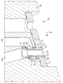
本発明に基づくさらなる溝壁掘削装置の詳細図が図2に示されている。図2は、本発明に基づく溝壁掘削機のフレーム20を示すもので、ガス供給ノズル50と液供給ノズル60とがフレーム20に設けられている。図2には、各ノズルを明快に示す関係上、掘削ホイールもその駆動装置も示されていない。
A detailed view of a further groove wall drilling device according to the present invention is shown in FIG. FIG. 2 shows a
液供給ノズル60に液を供給するため、液ライン68がフレーム20に設けられている。液供給ノズル60は、実質的に円筒形の液ノズルエレメント65に設けられた開口端部から形成されている。液ライン68の後に位置する流入部分では、液ノズルエレメント65はコーン状直円錐台部分62を備え、ここの液流路断面はテーパ状の先細り形状である。このコーン状直円錐台部分62の流れ方向には円筒形部分64が接続し、その先端に液供給ノズル60が設計されている。液ノズルエレメント65の円筒形部分64とコーン状直円錐台部分62とは、溝壁掘削機10の進行方向に平行に延びる中心軸に対して同軸に配置されている。
In order to supply the liquid to the
ガス供給ノズル50にガスを供給するため、ガスライン58がフレーム20に設けられている。ガスライン58はノズル60,50の部分で進行方向80に平行に延びているが、一方、液ライン68はこの方向にある角度を成して配置されている。
A
ガス供給ノズル50は、円形断面で設計された液ノズル60を囲む円環状ノズルとして設計される。ガス供給ノズル50は、液ノズルエレメント65の円筒形部分64の外壁と、液ノズルエレメント65の下部の円筒形部分64を囲む円環状孔エレメント51の開口路52の円筒状内壁との間に設計される。孔エレメント51は、交換可能のノズル保持具とも称されるが、フレーム20の下側に脱着自在に配置される。
The
ガス供給ノズル50にガスを供給するため、円環状チャンバ53がフレーム20に形成されている。この円環状チャンバ53は、孔エレメント51の上の円筒形部分64とコーン状直円錐台部分62を円環状に囲み、円環外壁に配置された開口を経由してガスライン58から流体が流れてくるように連結している。円環状チャンバ53の内部には、円筒形エレメント55が配置されている。円筒エレメント55の本体には、各々円い断面を有する4個の開口路56が設けられている。4個の開口路56は、進行方向80と一致する軸方向の周りに互いに各々90°の角度をなして配置されている。円環状チャンバ53から来るガスは、開口路56経由で半径方向内側に流れ、円筒エレメント55と液ノズルエレメント65の円筒形部分64に加えてコーン状直円錐台部分62との間に形成された中間スペース57に流入する。この中間スペース57から、ガスは今度は液ノズルエレメント65に沿って軸方向に孔エレメント51の開口路52に流入することができる。その結果、ガスはガス供給ノズル50へと流れる。
An
液ノズルエレメント65の流入側は、コーン状直円錐台部分62の箇所に広げられた端部71を備える。液ノズルエレメント65は、この端部で円筒エレメント55の上部面に支えられる。円筒エレメント55は、その下面の部分で孔エレメント51に支えられる。装置のメンテナンスを行う場合、円環状孔エレメント51をフレーム20から取り外すことができるので、円筒エレメント55も軸方向に動かし、取り外せる。こうすることにより、今度は液ノズルエレメント65を軸方向に外せる。
The inflow side of the
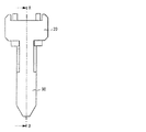
本発明に基づく溝壁掘削装置のさらなる実施の形態のフレーム20が図3と図4に示される。図3から分かるように、フレーム20の下側には、断面が減少した掘削シールド90が備えられる。その両側には、掘削ホイール(図3には図示せず)が支持される。
A
図3と図4に示されている実施の形態が図2に示されている実施の形態と本質的に相違する点は、液ノズルエレメント65の円筒形部分64の外壁に傾斜して保持されている円環状シールリップ92が円環状孔エレメント51に取り付けられていることである。ガス供給装置中に存在するガス圧力がガス供給ノズル50に存在する液の静水圧を超える場合は、シールリップ92が開くので、ガスは円環チャンバ53からガス供給ノズル50内に流入し、さらにそこから溝内に流入することができる。しかし、ガス供給装置中のガス圧力がガス供給ノズル50の液の静水圧より低い場合は、シールリップ92が閉じるので、ガス供給装置に懸濁物が流入するのが防止される。
The embodiment shown in FIGS. 3 and 4 is essentially different from the embodiment shown in FIG. 2 in that it is held in an inclined manner on the outer wall of the
さらに、図の実施の形態とは違って、図4の実施の形態のガス供給ノズル50は、円筒形状でなく、その下部はコーン状の設計となっている。
Furthermore, unlike the illustrated embodiment, the
1 掘削溝、3 土壌、10 溝壁掘削機、12,12’ 掘削ホイール、20 フレーム、40 作動流体供給ライン、50 ガス供給ノズル、51 円環状孔エレメント、52 開口路、53 円環状チャンバ、55 円筒エレメント、56 開口路、57 中間スペース、58 ガスライン、60 液供給ノズル、62 コーン状直円錐台部分、64 円筒形部分、65 液ノズルエレメント、68 液ライン、71 広げられた端部、80 掘削進行方向、90 掘削シールド、92 シールリップ。
DESCRIPTION OF
Claims (6)
周囲に掘削歯が設けられ回転駆動され二軸並行配置される少なくとも二つの溝壁掘削ホイールを有する溝壁掘削機を土壌中に降下する方向に進行させ、前記少なくとも二つの掘削ホイールを、前記進行の方向に対して角度をなして配置された回転軸を軸に回転させ、掘削ホイールの下に位置する土壌を削ることによって、掘削溝を形成し、更にこの掘削溝に固化性液体を供給し、掘削溝内の掘削ホイールが配置された箇所で掘削ホイールの作用によって前記固化性液体を削られた土壌と混ぜ合わせることで前記掘削溝自体の中で硬化性懸濁物を形成する方法において、
空気であるガスを、前記少なくとも2つの掘削ホイールの運転中に規定されたやり方で掘削溝内に供給し、
固化性液体とガスの双方を、前記溝壁掘削機のフレーム部分の掘削溝内に同時に供給し、
供給されたガスの流れおよび供給された固化性液体の流れを、少なくともほぼ前記進行の方向に向けて掘削ホイールに向けて導入し、
ガス用および固化性液体用の供給装置の吐出開口は、二軸並行配置された二つの掘削ホイールの間の中心に配置され、それによって、供給されたガスの流れおよび供給された固化性液体の流れが、二軸並行配置された2つの掘削ホイールに対して接線方向より接触し、
ガス供給の際に、固化性液体の流れの断面形状とガスの流れの断面形状の一方が、他方を囲むようにして同心円状に、ガスが掘削溝内に供給される、
ことを特徴とする方法。 A method of forming a groove wall in soil,
A groove wall excavator having at least two groove wall excavation wheels that are provided with excavating teeth and are rotationally driven and arranged in parallel on two axes is advanced in the direction of descending into the soil, and the at least two excavation wheels are A rotating shaft arranged at an angle with respect to the direction of the shaft is rotated about an axis, and the soil located under the excavating wheel is shaved to form a excavating groove, and further a solidifying liquid is supplied to the excavating groove. In the method of forming a curable suspension in the excavation groove itself by mixing the solidifying liquid with the soil shaved by the action of the excavation wheel at the location where the excavation wheel is disposed in the excavation groove ,
Supplying a gas, which is air, into the digging groove in a manner defined during operation of the at least two digging wheels ;
Supplying both solidifying liquid and gas simultaneously into the excavation groove of the frame portion of the groove wall excavator ;
Introducing a flow of supplied gas and a flow of supplied solidifying liquid toward the drilling wheel at least approximately in the direction of travel,
The discharge opening of the supply device for gas and solidifying liquid is arranged in the center between two drilling wheels arranged in parallel on two axes, so that the flow of supplied gas and the supply of solidifying liquid supplied The flow is in tangential contact with two drilling wheels arranged in parallel on two axes,
When supplying the gas, the gas is supplied into the excavation groove concentrically so that one of the cross-sectional shape of the solidifying liquid flow and the cross-sectional shape of the gas flow surrounds the other.
A method characterized by that.
フレームと、
フレームに回転自在に支持され、周囲に掘削歯が設けられ回転駆動され二軸並行配置される少なくとも二つの掘削ホイールと、
掘削ホイールに回転運動を起こさせるように設定し得る駆動装置と、
を備え、
前記少なくとも二つの掘削ホイールを、これの下に位置する土壌に降下する方向に進行させ、この土壌を削り、一方で掘削溝を形成する溝壁掘削装置において、
前記少なくとも二つの掘削ホイールは、前記進行の方向に対して角度をなして配置された回転軸を軸に回転駆動され、
ガス搬送装置が、前記掘削溝内にガスを規定されたやり方で供給するために設けられ、前記ガス搬送装置が、フレームに配置されてガスを少なくともほぼ前記進行の方向に向けて掘削ホイールに向けて供給するガス供給ノズルを備え、
液体搬送装置が、掘削溝内に固化性液体を供給するために設けられ、前記液体搬送装置が、フレームに配置されて固化性液体を少なくともほぼ前記進行方向に向けて掘削ホイールに向けて供給する液供給ノズルを備え、
前記ガス供給ノズルおよび液供給ノズルは、二軸並行配置された二つの掘削ホイールの間の中心に配置され、供給されるガスおよび固化性液体の流れが、二軸並行配置された二つの掘削ホイールの接線方向より接触し、
前記ガス供給ノズルが、前記液供給ノズルを囲んでおり、あるいはこの液供給ノズルによって囲まれており、
前記掘削ホイールが、掘削溝内の掘削ホイールが配置された箇所で前記供給された固化性液体と、削られた土壌とを混ぜ合わせ、前記掘削溝自体の中で硬化性懸濁液を形成する、
ことを特徴とする溝壁掘削装置。 A groove wall excavator for forming a groove wall,
Frame,
At least two excavating wheels supported rotatably on the frame, provided with excavating teeth around, rotated and arranged in parallel on two axes ;
A drive that can be set to cause the excavation wheel to rotate; and
With
In the groove wall excavator that advances the at least two excavating wheels in a direction of descending to the soil located below, and cuts the soil , while forming a excavation groove,
The at least two excavation wheels are driven to rotate about a rotation axis disposed at an angle with respect to the direction of travel;
A gas conveying device is provided for supplying gas in a defined manner into the excavation groove, the gas conveying device being arranged on a frame and directing the gas at least approximately in the direction of travel toward the excavation wheel and a gas supply nozzle for supplying Te,
A liquid transport device is provided for supplying solidifying liquid into the excavation groove, and the liquid transport device is disposed on the frame and supplies the solidifying liquid at least approximately in the direction of travel toward the drilling wheel. Equipped with a liquid supply nozzle,
The gas supply nozzle and the liquid supply nozzle are arranged at the center between two excavation wheels arranged in parallel with two axes, and the flow of the supplied gas and solidifying liquid is arranged in two excavation wheels arranged in parallel with two axes. From the tangential direction of
The gas supply nozzle surrounds or is surrounded by the liquid supply nozzle;
The excavation wheel mixes the supplied solidifying liquid with the shaved soil at the location of the excavation wheel in the excavation groove to form a curable suspension in the excavation groove itself. ,
A groove wall excavator characterized by that.
6. The apparatus according to claim 5 , wherein the gas conveying device includes a gas pressure generating device disposed outside the excavation groove.
Applications Claiming Priority (1)
| Application Number | Priority Date | Filing Date | Title |
|---|---|---|---|
| EP04019986A EP1630298B1 (en) | 2004-08-23 | 2004-08-23 | Method of making a slotted wall by means of a trench cutter |
Publications (2)
| Publication Number | Publication Date |
|---|---|
| JP2006057447A JP2006057447A (en) | 2006-03-02 |
| JP4205706B2 true JP4205706B2 (en) | 2009-01-07 |
Family
ID=34926269
Family Applications (1)
| Application Number | Title | Priority Date | Filing Date |
|---|---|---|---|
| JP2005237491A Active JP4205706B2 (en) | 2004-08-23 | 2005-08-18 | Method for forming groove wall in soil and groove wall excavating apparatus |
Country Status (14)
| Country | Link |
|---|---|
| US (1) | US7476057B2 (en) |
| EP (1) | EP1630298B1 (en) |
| JP (1) | JP4205706B2 (en) |
| KR (1) | KR100744953B1 (en) |
| CN (1) | CN100441784C (en) |
| AT (1) | ATE384169T1 (en) |
| CA (1) | CA2514638C (en) |
| DE (1) | DE502004005969D1 (en) |
| ES (1) | ES2299779T3 (en) |
| PL (1) | PL1630298T3 (en) |
| PT (1) | PT1630298E (en) |
| RU (1) | RU2307897C2 (en) |
| SG (1) | SG120280A1 (en) |
| SI (1) | SI1630298T1 (en) |
Families Citing this family (15)
| Publication number | Priority date | Publication date | Assignee | Title |
|---|---|---|---|---|
| FR2899608B1 (en) * | 2006-04-06 | 2010-04-16 | Cie Du Sol | DRILLING TOOLS |
| CN102146688B (en) * | 2011-01-01 | 2014-11-05 | 广东梅雁吉祥水电股份有限公司 | Gas-lift four-shaft groove forming machine |
| CN102352642B (en) * | 2011-07-09 | 2013-06-19 | 牛伟民 | Pneumatic slotting drill bit |
| CN102587353A (en) * | 2011-11-09 | 2012-07-18 | 龙工(上海)机械制造有限公司 | Stirring head of stirring curing machine |
| CN102587434B (en) * | 2012-03-19 | 2014-11-12 | 牛伟民 | Modified pneumatic slotting drill |
| EP2685007B1 (en) * | 2012-07-10 | 2015-01-07 | BAUER Maschinen GmbH | Roue de fraisage pour une fraise pour paroi moulée |
| CN104594424A (en) * | 2013-10-31 | 2015-05-06 | 中铁西北科学研究院有限公司 | Excavation equipment of slide-resistant pile foundation pit |
| CN103770224B (en) * | 2014-01-29 | 2016-06-01 | 徐工集团工程机械股份有限公司 | The feeding device of a kind of two-wheel groove milling machine and two-wheel groove milling machine |
| EP3296468B1 (en) * | 2016-09-15 | 2019-11-06 | BAUER Maschinen GmbH | Method and trench cutter for creating a slit in the ground |
| FR3071535B1 (en) * | 2017-09-25 | 2019-09-27 | Soletanche Freyssinet | DRILLING MACHINE FOR CARRYING OUT A NON-RECTILINE TRENCH |
| EP3543408B1 (en) * | 2018-03-21 | 2020-10-21 | BAUER Spezialtiefbau GmbH | Slurry wall mill and method for creating a milled slit in the ground |
| CN108680725B (en) * | 2018-04-13 | 2020-11-20 | 白云兵 | Soil detection excavation test device |
| EP3556942B1 (en) * | 2018-04-18 | 2020-04-29 | BAUER Maschinen GmbH | Cutter for making a diaphragma wall and method of making such wall |
| KR102235301B1 (en) | 2018-12-05 | 2021-04-02 | 한국지질자원연구원 | Trench planarization electromotion device |
| DE102018131226A1 (en) * | 2018-12-06 | 2020-06-10 | Liebherr-Werk Nenzing Gmbh | Special civil engineering machine, especially trench cutter |
Family Cites Families (16)
| Publication number | Priority date | Publication date | Assignee | Title |
|---|---|---|---|---|
| CH490579A (en) * | 1969-02-27 | 1970-05-15 | Bade & Co Gmbh | Milling tool for diaphragm wall machines |
| JPS5217646B2 (en) * | 1972-07-28 | 1977-05-17 | ||
| US4084648A (en) * | 1976-02-12 | 1978-04-18 | Kajima Corporation | Process for the high-pressure grouting within the earth and apparatus adapted for carrying out same |
| DE3424999C2 (en) | 1984-07-06 | 1994-01-13 | Bauer Spezialtiefbau | Trench cutter |
| DE3715977A1 (en) * | 1987-05-13 | 1988-12-01 | Bauer Spezialtiefbau | ROOM DEVICE |
| DE4008207A1 (en) * | 1990-03-15 | 1990-08-23 | Bilfinger Berger Bau | Retention wall construction system - with binding agents or solids fed into trench after cutting |
| DE4141629C2 (en) * | 1991-12-17 | 1997-02-20 | Bauer Spezialtiefbau | Process for the production of sealing walls |
| US5829925A (en) | 1994-08-23 | 1998-11-03 | H. Granlund Tools Kb | Coolant actuated rear-end countersinking tool |
| DE19530827C2 (en) | 1995-08-22 | 1999-04-01 | Bauer Spezialtiefbau | Method and device for producing diaphragm walls |
| JP3750186B2 (en) * | 1996-04-08 | 2006-03-01 | 株式会社大林組 | Construction method of underground continuous wall |
| DE19652835C1 (en) * | 1996-12-18 | 1998-03-26 | Bauer Spezialtiefbau | Subterranean cutter dredger |
| CN2390918Y (en) * | 1999-09-02 | 2000-08-09 | 上海宝钢冶金建设公司 | Apparatus for underground continuous wall airlift reverse circulation cleaning out and displacing bulk head stabilizing solution |
| FR2806111B1 (en) * | 2000-03-13 | 2002-06-14 | Cie Du Sol | HARD GROUND DRILLING APPARATUS |
| EP1342851A1 (en) * | 2002-03-08 | 2003-09-10 | BVV Spezialtiefbautechnik Vertriebs GmbH | Method and apparatus for forming a soil-concrete trench wall |
| DE10308539B3 (en) * | 2003-02-27 | 2004-06-03 | Bauer Maschinen Gmbh | Cutting device for cutting grooves in the ground comprises cutting elements arranged on the cutting wheels to remove soil using a rotary action |
| DE10308538C5 (en) | 2003-02-27 | 2014-11-06 | Bauer Maschinen Gmbh | Method of making a trench wall in the ground, trench wall cutter and trench wall cutter |
-
2004
- 2004-08-23 PL PL04019986T patent/PL1630298T3/en unknown
- 2004-08-23 PT PT04019986T patent/PT1630298E/en unknown
- 2004-08-23 EP EP04019986A patent/EP1630298B1/en active Active
- 2004-08-23 ES ES04019986T patent/ES2299779T3/en active Active
- 2004-08-23 DE DE502004005969T patent/DE502004005969D1/en active Active
- 2004-08-23 AT AT04019986T patent/ATE384169T1/en active
- 2004-08-23 SI SI200430617T patent/SI1630298T1/en unknown
-
2005
- 2005-08-04 CA CA002514638A patent/CA2514638C/en active Active
- 2005-08-08 RU RU2005125078/03A patent/RU2307897C2/en not_active IP Right Cessation
- 2005-08-18 JP JP2005237491A patent/JP4205706B2/en active Active
- 2005-08-19 SG SG200505311A patent/SG120280A1/en unknown
- 2005-08-19 US US11/206,857 patent/US7476057B2/en active Active
- 2005-08-22 KR KR1020050076626A patent/KR100744953B1/en not_active IP Right Cessation
- 2005-08-23 CN CNB2005100966338A patent/CN100441784C/en active Active
Also Published As
| Publication number | Publication date |
|---|---|
| SG120280A1 (en) | 2006-03-28 |
| CN1746433A (en) | 2006-03-15 |
| EP1630298B1 (en) | 2008-01-16 |
| ATE384169T1 (en) | 2008-02-15 |
| US20060039759A1 (en) | 2006-02-23 |
| RU2307897C2 (en) | 2007-10-10 |
| US7476057B2 (en) | 2009-01-13 |
| CA2514638C (en) | 2009-10-27 |
| SI1630298T1 (en) | 2008-06-30 |
| CA2514638A1 (en) | 2006-02-23 |
| CN100441784C (en) | 2008-12-10 |
| RU2005125078A (en) | 2007-02-20 |
| PT1630298E (en) | 2008-02-14 |
| EP1630298A1 (en) | 2006-03-01 |
| KR100744953B1 (en) | 2007-08-02 |
| PL1630298T3 (en) | 2008-05-30 |
| ES2299779T3 (en) | 2008-06-01 |
| JP2006057447A (en) | 2006-03-02 |
| KR20060053197A (en) | 2006-05-19 |
| DE502004005969D1 (en) | 2008-03-06 |
Similar Documents
| Publication | Publication Date | Title |
|---|---|---|
| JP4205706B2 (en) | Method for forming groove wall in soil and groove wall excavating apparatus | |
| KR100572023B1 (en) | Method for Making A Trench Wall in The Ground, Trench Wall Cutter And Trench Wall Cutting device | |
| JP4109687B2 (en) | Apparatus and method for providing groove walls in soil | |
| JPS5932618B2 (en) | Method of creating a waterproof shield in soil using a nozzle and apparatus for carrying out this method | |
| JP2017040050A (en) | Tunnel excavator | |
| JP2007332710A (en) | Ground improvement method and ground improving machine | |
| JP6942001B2 (en) | High pressure injection device | |
| JP2007204983A (en) | Swivel for soil excavating tool, and soil improving method | |
| JP2011157748A (en) | Slime processing device | |
| ITMI20072322A1 (en) | DRILLING DEVICE | |
| JP2007009502A (en) | Soil excavating tool, soil improvement method, and soil decontamination method | |
| JP4695734B2 (en) | Soil excavation tool and soil improvement method | |
| JP2009057748A (en) | Agitator for shallow ground improvement, shallow ground improver, shallow ground improvement system, construction method for improving shallow ground, and construction method for improving contaminated soil | |
| JP7231271B1 (en) | Ground improvement method and ground improvement device | |
| JP5241896B2 (en) | Method and apparatus for improving efficiency of water jet including abrasive jet in water | |
| JP2018096086A (en) | Tunnel excavator | |
| RU2426857C1 (en) | Thermal-mechanical drilling device for hard mine rocks | |
| JP6878764B2 (en) | Drilling stirrer | |
| JPH11319792A (en) | Soil improvement using coated soil improvement agent | |
| JP2934038B2 (en) | Soil drilling method and device | |
| JP2005307524A (en) | Soil excavator | |
| JP2001098576A (en) | Underwater excavator | |
| JP2005248435A (en) | Excavator | |
| JP2021098969A (en) | Center cutter for tunneling machine | |
| JP5521666B2 (en) | Construction method of soil cement wall |
Legal Events
| Date | Code | Title | Description |
|---|---|---|---|
| A131 | Notification of reasons for refusal |
Free format text: JAPANESE INTERMEDIATE CODE: A131 Effective date: 20070424 |
|
| A601 | Written request for extension of time |
Free format text: JAPANESE INTERMEDIATE CODE: A601 Effective date: 20070724 |
|
| A602 | Written permission of extension of time |
Free format text: JAPANESE INTERMEDIATE CODE: A602 Effective date: 20070727 |
|
| A521 | Request for written amendment filed |
Free format text: JAPANESE INTERMEDIATE CODE: A523 Effective date: 20070821 |
|
| A131 | Notification of reasons for refusal |
Free format text: JAPANESE INTERMEDIATE CODE: A131 Effective date: 20071016 |
|
| A601 | Written request for extension of time |
Free format text: JAPANESE INTERMEDIATE CODE: A601 Effective date: 20080116 |
|
| A602 | Written permission of extension of time |
Free format text: JAPANESE INTERMEDIATE CODE: A602 Effective date: 20080121 |
|
| A521 | Request for written amendment filed |
Free format text: JAPANESE INTERMEDIATE CODE: A523 Effective date: 20080122 |
|
| A02 | Decision of refusal |
Free format text: JAPANESE INTERMEDIATE CODE: A02 Effective date: 20080422 |
|
| A521 | Request for written amendment filed |
Free format text: JAPANESE INTERMEDIATE CODE: A523 Effective date: 20080821 |
|
| A911 | Transfer to examiner for re-examination before appeal (zenchi) |
Free format text: JAPANESE INTERMEDIATE CODE: A911 Effective date: 20080828 |
|
| TRDD | Decision of grant or rejection written | ||
| A01 | Written decision to grant a patent or to grant a registration (utility model) |
Free format text: JAPANESE INTERMEDIATE CODE: A01 Effective date: 20080930 |
|
| A01 | Written decision to grant a patent or to grant a registration (utility model) |
Free format text: JAPANESE INTERMEDIATE CODE: A01 |
|
| A61 | First payment of annual fees (during grant procedure) |
Free format text: JAPANESE INTERMEDIATE CODE: A61 Effective date: 20081016 |
|
| FPAY | Renewal fee payment (event date is renewal date of database) |
Free format text: PAYMENT UNTIL: 20111024 Year of fee payment: 3 |
|
| R150 | Certificate of patent or registration of utility model |
Free format text: JAPANESE INTERMEDIATE CODE: R150 Ref document number: 4205706 Country of ref document: JP Free format text: JAPANESE INTERMEDIATE CODE: R150 |
|
| FPAY | Renewal fee payment (event date is renewal date of database) |
Free format text: PAYMENT UNTIL: 20111024 Year of fee payment: 3 |
|
| FPAY | Renewal fee payment (event date is renewal date of database) |
Free format text: PAYMENT UNTIL: 20121024 Year of fee payment: 4 |
|
| R250 | Receipt of annual fees |
Free format text: JAPANESE INTERMEDIATE CODE: R250 |
|
| FPAY | Renewal fee payment (event date is renewal date of database) |
Free format text: PAYMENT UNTIL: 20121024 Year of fee payment: 4 |
|
| FPAY | Renewal fee payment (event date is renewal date of database) |
Free format text: PAYMENT UNTIL: 20131024 Year of fee payment: 5 |
|
| R250 | Receipt of annual fees |
Free format text: JAPANESE INTERMEDIATE CODE: R250 |
|
| R250 | Receipt of annual fees |
Free format text: JAPANESE INTERMEDIATE CODE: R250 |
|
| R250 | Receipt of annual fees |
Free format text: JAPANESE INTERMEDIATE CODE: R250 |
|
| R250 | Receipt of annual fees |
Free format text: JAPANESE INTERMEDIATE CODE: R250 |
|
| R250 | Receipt of annual fees |
Free format text: JAPANESE INTERMEDIATE CODE: R250 |
|
| R250 | Receipt of annual fees |
Free format text: JAPANESE INTERMEDIATE CODE: R250 |
|
| R250 | Receipt of annual fees |
Free format text: JAPANESE INTERMEDIATE CODE: R250 |
|
| R250 | Receipt of annual fees |
Free format text: JAPANESE INTERMEDIATE CODE: R250 |
|
| R250 | Receipt of annual fees |
Free format text: JAPANESE INTERMEDIATE CODE: R250 |
|
| R250 | Receipt of annual fees |
Free format text: JAPANESE INTERMEDIATE CODE: R250 |
|
| R250 | Receipt of annual fees |
Free format text: JAPANESE INTERMEDIATE CODE: R250 |
|
| R250 | Receipt of annual fees |
Free format text: JAPANESE INTERMEDIATE CODE: R250 |