JP2009057748A - Agitator for shallow ground improvement, shallow ground improver, shallow ground improvement system, construction method for improving shallow ground, and construction method for improving contaminated soil - Google Patents
Agitator for shallow ground improvement, shallow ground improver, shallow ground improvement system, construction method for improving shallow ground, and construction method for improving contaminated soil Download PDFInfo
- Publication number
- JP2009057748A JP2009057748A JP2007226012A JP2007226012A JP2009057748A JP 2009057748 A JP2009057748 A JP 2009057748A JP 2007226012 A JP2007226012 A JP 2007226012A JP 2007226012 A JP2007226012 A JP 2007226012A JP 2009057748 A JP2009057748 A JP 2009057748A
- Authority
- JP
- Japan
- Prior art keywords
- shallow ground
- stirring
- improving
- improvement
- stirrer
- Prior art date
- Legal status (The legal status is an assumption and is not a legal conclusion. Google has not performed a legal analysis and makes no representation as to the accuracy of the status listed.)
- Pending
Links
Images


Abstract
Description
本発明は、浅層地盤改良用攪拌機、とりわけ、高圧噴射装置を組み合わせた浅層地盤改良用攪拌機に関する。浅層地盤改良に用いるだけでなく、汚染土壌改良にも用いることができる。 The present invention relates to a shallow ground improvement stirrer, and more particularly to a shallow ground improvement stirrer combined with a high-pressure injection device. It can be used not only for improving shallow ground but also for improving contaminated soil.
従来から行われている浅層の地盤改良工法及び汚染土壌改良工法は、粉体またはスラリーの低圧吐出(3Mpa程度以下)での改良材の混合攪拌である。 The shallow ground improvement method and the contaminated soil improvement method that have been conventionally performed are mixing and stirring of the improved material by low-pressure discharge (less than about 3 MPa) of powder or slurry.
特許文献1には、油圧式ショベル系掘削機のアーム先端部に取着可能な台部材、該台部材の下部両側には支持フレームが垂設され、該支持フレームの先端寄りには、所要数の羽根板を有する回転軸が軸支され、回転軸の一端側には回転軸を駆動する駆動機構部が設けてあり、各支持フレームの右端側には、土砂掻き寄せ部材が上下方向に回動可能に軸支されている地盤改良用攪拌機が開示されている。
特許文献2には、上下に長く所定の間隔で並行に設けた上下動できる支持部の下部を連結するように回転軸を設け、この回転軸に薄く四角形状の回転盤を所定の間隔あけて5枚軸支し、回転盤の四角形状の角部から立ち上がりしかも回転軸方向に湾曲した攪拌羽根を設け、支持部の上部に油圧モータを設け、回転軸と油圧モータの出力軸にスプロケットを設け、スプロケットにチェーンをかけ渡し、抵抗少なく浅層地盤の攪拌を行える地盤改良用攪拌機が開示されている。
In Patent Document 2, a rotating shaft is provided so as to connect a lower part of a support portion that is vertically long and is provided in parallel at a predetermined interval and can be moved up and down, and a thin rectangular rotating disk is provided at a predetermined interval on the rotating shaft. A stirrer blade that is supported by five shafts, rises from the square corner of the rotating disk and is curved in the direction of the rotating shaft, a hydraulic motor is provided above the support, and a sprocket is provided on the rotating shaft and the output shaft of the hydraulic motor In addition, a ground improvement stirrer is disclosed in which a chain is placed over a sprocket and a shallow ground can be stirred with less resistance.
解決しようとする問題点は、従来技術が攪拌機の回転翼のみの掘削・混合攪拌であり、土質により攪拌不良が起こりやすい点である。また、硬質地盤の場合は、回転トルクの大きい攪拌機が必要になり、機械が大型化するという点である。さらに、改良地盤が粘性土質(粘土質)の場合は、回転翼に土が多量に付着し、回転翼と土の供回り減少が発生し、攪拌不良となる点である。さらにまた、改良体が粉体の場合は、攪拌前や攪拌時に改良材が周囲に飛散し、環境を損なう点である The problem to be solved is that the prior art is excavation / mixing agitation only with the rotor blades of the agitator, and the agitation failure tends to occur due to the soil quality. Further, in the case of hard ground, a stirrer having a large rotational torque is required, which increases the size of the machine. Furthermore, when the improved ground is viscous soil (clay), a large amount of soil adheres to the rotor blades, and the rotation of the rotor blades and the soil decreases, resulting in poor stirring. Furthermore, when the improved body is a powder, the improved material scatters to the surroundings before or during stirring, which is a point that damages the environment.
かかる課題を解決すべく、本発明に係る浅層地盤改良用攪拌機は、改良を必要とする浅層地盤を攪拌する攪拌部材を有し、油圧式ショベル系掘削機のアーム先端部に取り付けて使用する浅層地盤改良用攪拌機であって、前記攪拌部材により攪拌される土壌に向けて改良材を高圧噴射する高圧噴射装置を設けたものである。 In order to solve this problem, the agitator for improving the shallow ground according to the present invention has a stirring member for agitating the shallow ground that needs improvement, and is used by being attached to the tip of the arm of a hydraulic excavator excavator. This is a shallow ground improvement stirrer that is provided with a high-pressure injection device for high-pressure injection of the improvement material toward the soil stirred by the stirring member.
さらに、前記高圧噴射装置は、固定式ノズルを複数有し、前記攪拌部材で攪拌される範囲の土壌に向けて改良材を高圧噴射するものとすることができる。 Furthermore, the said high pressure injection apparatus shall have two or more fixed nozzles, and shall inject the improvement material at high pressure toward the soil of the range stirred with the said stirring member.
また、前記高圧噴射装置は、揺動式ノズルを有し、前記攪拌部材で攪拌される範囲の土壌に向けて揺動しつつ、改良材を高圧噴射するものとしてもよい。 The high-pressure spraying device may have a swinging nozzle and sprays the improving material at a high pressure while swinging toward the soil in the range stirred by the stirring member.
本発明に係る浅層地盤改良用攪拌機は、左右両側に左側板、右側板を有し、先端に複数の掘削刃、左先端側板、右先端側板を有するバケットと、該バケットを前記アームに取り付けるアーム取付部と、前記バケットの左側板の中央から右側板の中央までの間であって、前記バケットの内側に前記アームの延びる方向に対して垂直方向に設けられ、回転可能な攪拌軸と、該攪拌軸の外側に複数設けた攪拌翼と、前記バケットの左側板または右側板のいずれかの中央に取り外し可能に固定されたモータ取付板と、該モータ取付板の内側に取り付けた油圧モータと、該油圧モータの動力を前記攪拌軸に伝達する動力伝達機構と、前記バケットのアーム取付部付近に設け、前記掘削刃付近に向けて改良材を高圧噴射する噴射ノズルと、該噴射ノズルへ改良材を供給すべく前記バケット上部に設けた改良材供給管とを有する。 A stirrer for improving shallow ground according to the present invention has a left side plate and a right side plate on both right and left sides, a bucket having a plurality of excavating blades, a left front end side plate, and a right front end side plate at a tip, and the bucket is attached to the arm. An agitation shaft provided between the arm attachment portion and the center of the left side plate of the bucket to the center of the right side plate, and provided in a direction perpendicular to the extending direction of the arm inside the bucket, and rotatable; A plurality of stirring blades provided on the outside of the stirring shaft; a motor mounting plate removably fixed to the center of either the left side plate or the right side plate of the bucket; and a hydraulic motor attached to the inner side of the motor mounting plate; A power transmission mechanism that transmits the power of the hydraulic motor to the stirring shaft, an injection nozzle that is provided near the arm mounting portion of the bucket and that injects the improved material at a high pressure toward the vicinity of the excavating blade, and the injection nozzle And a modifying material supply pipe provided in the bucket top to supply Ryozai.
また、本発明に係る浅層地盤改良用攪拌機は、改良材供給管を内側に有し、鉛直方向に延びる攪拌装置と、該攪拌装置を前記アームに取り付けるアーム取付部と、前記攪拌装置の下方先端部に取り付けた掘削ビットと、該掘削ビットの上部であって前記攪拌装置を貫いて前記攪拌装置に対して垂直方向に延びる攪拌用回転軸と、該攪拌用回転軸に複数設けた攪拌翼と、前記攪拌装置内に設けた油圧モータと、該油圧モータの動力を前記攪拌用回転軸に伝達する動力伝達機構と、前記攪拌翼により攪拌される土壌に向けて前記改良材供給管から供給される改良材を高圧噴射すべく前記攪拌装置上に設けた噴射ノズルとを有する。 The shallow ground improvement stirrer according to the present invention includes a stirrer having an improvement material supply pipe on the inner side and extending in the vertical direction, an arm mounting portion for attaching the stirrer to the arm, and a lower portion of the stirrer An excavation bit attached to the tip, an agitation rotating shaft that extends above the excavation bit and extends in a direction perpendicular to the agitation device, and a plurality of agitation blades provided on the agitation rotation shaft A hydraulic motor provided in the stirring device, a power transmission mechanism for transmitting the power of the hydraulic motor to the rotating shaft for stirring, and supplied from the improvement material supply pipe toward the soil stirred by the stirring blade And an injection nozzle provided on the stirring device for high-pressure injection of the improved material.
前記浅層地盤改良用攪拌機を油圧式ショベル系掘削機のアーム先端部に取り付けて浅層地盤改良機とすることができる。 The shallow ground improvement stirrer can be attached to the tip of the arm of a hydraulic excavator excavator to form a shallow ground improvement machine.
その浅層地盤改良機に加えて、前記高圧噴射装置に対して改良材を供給するグラウトポンプと、該グラウトポンプに対して、セメントと水とを混合して供給するミキシングプラントと、該ミキシングプラント及び前記グラウトポンプに対して電力を供給する発電機とを有する浅層地盤改良システムを構成することができる。 In addition to the shallow ground improvement machine, a grout pump for supplying an improvement material to the high-pressure injection device, a mixing plant for supplying cement and water mixed to the grout pump, and the mixing plant And the shallow ground improvement system which has the generator which supplies electric power with respect to the said grout pump can be comprised.
本発明に係る浅層地盤改良工法は、前記浅層地盤改良機を用いて浅層地盤を改良する浅層地盤改良工法であって、改良を必要とする浅層地盤を前記攪拌部材を用いて攪拌する攪拌工程と、該攪拌工程において攪拌される土壌に向けて改良材を高圧噴射する高圧噴射工程とを有するものである。 The shallow ground improvement method according to the present invention is a shallow ground improvement method for improving a shallow ground using the shallow ground improvement machine, and a shallow ground that requires improvement is used for the shallow ground. It has a stirring step of stirring, and a high-pressure spraying step of spraying the improved material at a high pressure toward the soil stirred in the stirring step.
本発明に係る汚染土壌改良工法は、前記浅層地盤改良機を用いて汚染土壌を改良する汚染土壌改良工法であって、改良を必要とする汚染土壌を前記攪拌部材を用いて攪拌する攪拌工程と、該攪拌工程において攪拌される土壌に向けて改良材を高圧噴射する高圧噴射工程とを有するものである。 The contaminated soil improvement method according to the present invention is a contaminated soil improvement method for improving contaminated soil using the shallow ground improvement machine, and agitating step of agitating contaminated soil requiring improvement using the agitating member And a high-pressure injection step of high-pressure injection of the improving material toward the soil stirred in the stirring step.
本発明は、このように構成されているから、改良材を高圧噴射(5〜40Mpa)することで、その噴射エネルギーによる掘削・攪拌と回転翼による攪拌とで作業能率が格段に向上し施行時間の短縮が可能となる。また、噴射エネルギーを使うことで、浅層のみならず中層までの改良が可能となる。本来中層の地盤改良に必要な機材を不要とすることから施行コストの低減につながる。 Since the present invention is configured as described above, the working efficiency is greatly improved by excavating / stirring by the injection energy and stirring by the rotor blades by performing high-pressure injection (5 to 40 Mpa) of the improved material. Can be shortened. Further, by using the injection energy, it is possible to improve not only the shallow layer but also the middle layer. This eliminates the need for equipment that is essentially required for ground improvement in the middle class, leading to a reduction in enforcement costs.
硬質地盤でも高圧噴射による掘削ができるので機械の小型化が可能になる。 Since the excavation by high-pressure injection can be performed even on hard ground, the machine can be downsized.
粘性土の場合でも攪拌機の回転翼付近に高圧噴射することで、回転翼に土の付着がなく供回り減少が発生しない。 Even in the case of cohesive soil, high pressure injection near the rotating blades of the stirrer prevents the rotating blades from adhering to the soil and reducing the rotation.
固定式噴射ノズルを設けた浅層地盤改良用攪拌機と、揺動式噴射ノズルを設けた浅層地盤改良用攪拌機とを、対象地盤、噴射量、噴射圧力等に応じて使い分けることでさらに効率のよい改良工事が可能となる。 By using a shallow ground improvement stirrer with a fixed injection nozzle and a shallow ground improvement stirrer with a swinging injection nozzle, depending on the target ground, injection amount, injection pressure, etc. Good improvement work is possible.
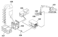
以下、本発明を実施するための最良の形態を説明する。図1は、本発明を用いて実際に地盤改良工法を実施する際の典型的なシステム例を示す図である。本発明に係る地盤改良用攪拌機108を油圧式ショベル系掘削機のアーム先端部に取り付けて浅層地盤改良機101とする。改良土(地盤改良を必要とする土壌)100の土質がいかなるものかによって、浅層地盤改良用攪拌機をバケットタイプにするか、ロッドタイプにするか、噴射ノズルを固定式のものにするか、揺動式のものにするか、を選択することができる。図1では、バケットタイプのものを描いてある。
Hereinafter, the best mode for carrying out the present invention will be described. FIG. 1 is a diagram showing a typical system example when the ground improvement method is actually implemented using the present invention. A ground improvement stirrer 108 according to the present invention is attached to the tip of an arm of a hydraulic excavator excavator to form a shallow
地盤改良用攪拌機108にはスイベルが設けられ、グラウトポンプから圧送される改良材(または水)はスイベルを介して地盤改良用攪拌機108内の噴射ノズルから高圧噴射される。水タンク107内にある水とセメントサイロ106内のセメントとがミキシングプラント103にて混合され、流量計104を介してグラウトポンプ102に供給される。発電機105がグラウトポンプ102、ミキシングプラント103などへの電力を供給する。
The
浅層地盤改良用攪拌機の具体的な形状は、バケットのタイプのものと、ロッドのタイプのものとがある。それぞれについて固定式ノズル、揺動式ノズルを組み合わせることで、4つの実施例を挙げることができる。実施例1,2,3及び4の特徴の違いについて簡単に言及する。実施例1は、バケットの内側に攪拌翼を設け固定式の噴射ノズルを4個設けたものである。実施例2は、バケットの内側に攪拌翼を設け揺動式ノズルを2個設けたものである。実施例3は、ロッドの先端に掘削ビット、ロッドに直交する回転軸、回転軸に取り付けた攪拌翼、攪拌翼に向けて固定式の噴射ノズルを2個設けたものである。実施例4は、ロッドの先端に掘削ビット、ロッドに直交する回転軸、回転軸に取り付けた攪拌翼、攪拌翼に向けて揺動式の噴射ノズルを1個設けたものである。 Specific shapes of the stirrer for improving the shallow ground include a bucket type and a rod type. Four examples can be given by combining a fixed nozzle and a swinging nozzle for each. The difference in the features of Examples 1, 2, 3, and 4 will be briefly described. In Example 1, a stirring blade is provided inside a bucket and four fixed injection nozzles are provided. In Example 2, a stirring blade is provided inside the bucket, and two oscillating nozzles are provided. In Example 3, a drill bit, a rotating shaft orthogonal to the rod, a stirring blade attached to the rotating shaft, and two fixed injection nozzles toward the stirring blade are provided at the tip of the rod. In Example 4, a drill bit, a rotating shaft orthogonal to the rod, a stirring blade attached to the rotating shaft, and one oscillating jet nozzle toward the stirring blade are provided at the tip of the rod.
図5は、バケットの内側に攪拌翼を設け固定式の噴射ノズルを4個設けた実施例を示す図である。図5aは、油圧式ショベル系掘削機の操縦席に座って操作する操作者から見て左側から見た側面図である。図5bは、油圧式ショベル系掘削機の操縦席に座って操作する操作者から見て正面図である。以下、本明細書において、左右、正面というときは、油圧式ショベル系掘削機の操縦席から見て論ずることとする。 FIG. 5 is a view showing an embodiment in which stirring blades are provided inside the bucket and four fixed injection nozzles are provided. FIG. 5a is a side view of the hydraulic excavator excavator as seen from the left side when viewed from the operator who operates by sitting on the cockpit. FIG. 5b is a front view seen from an operator who sits and operates in the cockpit of the hydraulic excavator excavator. Hereinafter, in the present specification, the terms “left / right” and “front” will be discussed from the cockpit of a hydraulic excavator excavator.
バケット500の先端には、掘削刃503が設けられており、図1の地盤改良機101の操縦者が油圧式アームを操作して動かすとき又は油圧式アームを固定したまま地盤改良機101のキャタピラを用いて前進・後退するときに、掘削刃503が改良土100を掘削するように働く。バケット500を構成する左側板501、右側板502には、その先端にそれぞれ左先端側板504、右先端側板505が設けられており、土砂が脇からこぼれ落ちるのを防止する。アーム取付部506は、バケット500ひいては地盤改良用攪拌機108を地盤改良機101のアームにしっかりと固定する。取り外し可能としているのは、その地盤の土質などの条件により、バケットタイプのものとロッドタイプのものを変更したり、噴射ノズルが固定式のものと揺動式のものとの交換を可能とするためである。
An
バケット500の左側板501の中央から右側板502の中央までの間であって、バケット500の内側に、アームの延びる方向に対して垂直方向に攪拌軸507が設けられる。この攪拌軸507は、回転可能なものであって、その外側には複数の攪拌翼508が設けられる。バケット500の左側面又は右側面のいずれかの中央には取り外し可能に固定されたモータ取付板509が設けられる。取り外し可能としたのは、油圧モータ510及び動力伝達機構511のメンテナンスのためである。動力伝達機構511としては、歯車あるいはスプロケットにチェーンをかけたものを用いることができる。
A
バケット500の上部であって、アーム取付部に近いあたりには、改良材(又は水)を高圧噴射する噴射ノズル512が設けられる。図5の例では、4個ならべて配置してある。その向きは、掘削刃503のあたりに改良材が噴射されるような向きである。高圧噴射とは、5Mpaから40Mpa程度の圧力である。図5の例では、固定式ノズルとしてある。固定式の場合、ノズルの数は2個から5個程度が望ましい。図5にははっきりと図示されていないが、噴射ノズル512へ改良材を供給すべくバケット500上部には、改良材供給管513が設けられている。
An
図7は、バケットタイプの浅層地盤改良用攪拌機を用いて地盤改良工法を実施する際の様子を示す図である。前述したように油圧式アームを操作することによっても、アームを固定したまま地盤改良機が前進又は後退することによっても、掘削がなされる。掘削作業と、噴射ノズルからの地盤改良材の高圧噴射と、浅層地盤改良用攪拌機による攪拌とは、同時並行的になされ得る。実際には、地盤改良機を扱う操縦者と、図1に示すグラウトポンプ102を扱う操作者とが、協働して地盤改良作業を行うから、必要に応じて、噴射を止めて、掘削と攪拌だけを行ったり、掘削だけ、あるいは、攪拌だけを行う作業もあり得る。高圧噴射を用いることで、噴射エネルギーを利用してより効果的な掘削をすることが期待できる。
FIG. 7 is a view showing a state when the ground improvement method is carried out using a bucket type shallow ground improvement stirrer. As described above, excavation is performed either by operating the hydraulic arm or by moving the ground improvement machine forward or backward with the arm fixed. The excavation work, the high-pressure injection of the ground improvement material from the injection nozzle, and the stirring by the stirrer for shallow ground improvement can be performed in parallel. Actually, the operator who handles the ground improvement machine and the operator who handles the
図6は、バケットの内側に攪拌翼を設け揺動式の噴射ノズルを2個設けた実施例を示す図である。図6aは、左側から見た側面図であり、図6bは、正面から見た図である。図6の構成は、図5の構成とほぼ同じである。違うのは、噴射ノズルが固定式ではなく揺動式である点、そして噴射ノズルの個数が4個ではなくて2個である点である。揺動式の場合も、噴射圧力は5Mpaから40Mpaを用いる。ノズルの数は1個又は2個が望ましい。ノズル揺動回数は30〜120cpm(一分間に30〜120回)が適当である。ノズルを揺動させる手段は、油圧モータによる。 FIG. 6 is a diagram showing an embodiment in which stirring blades are provided inside the bucket and two swinging injection nozzles are provided. FIG. 6A is a side view seen from the left side, and FIG. 6B is a view seen from the front side. The configuration of FIG. 6 is almost the same as the configuration of FIG. The difference is that the injection nozzle is not a fixed type but a rocking type, and the number of injection nozzles is two instead of four. Also in the case of the swing type, the injection pressure is 5 MPa to 40 MPa. The number of nozzles is preferably one or two. The number of nozzle oscillations is suitably 30 to 120 cpm (30 to 120 times per minute). The means for swinging the nozzle is a hydraulic motor.
図2は、ロッドタイプの攪拌装置に攪拌翼を設け固定式の噴射ノズルを2個設けた実施例を示す図である。図2aは、左側面から見た図であり、図2bは、正面から見た図である。鉛直方向に延びる攪拌装置200は、改良材供給管213を内部に有している。攪拌装置200の上端には油圧モータ214が設けられて、油圧ショベルからの油圧源が供給される。攪拌装置200は、アーム取付部206により地盤改良機のアームに頑丈に取り付けられる。攪拌装置200の下端部には掘削ビット203が設けられる。掘削ビット203の上部であって攪拌装置200を貫いてロッド200に対して垂直方向に延びる方向に攪拌用回転軸207が設けられ、攪拌用回転軸207から放射状に複数の攪拌翼208が設けられる。
FIG. 2 is a view showing an embodiment in which a stirring blade is provided in a rod type stirring device and two fixed injection nozzles are provided. 2a is a view from the left side, and FIG. 2b is a view from the front. The stirring
攪拌用回転軸207は、回転自在に設けられるが、それを回転する駆動力は油圧モータ214によって与えられる。油圧モータ214は、攪拌装置200の上部に固定され、地盤改良機101の油圧源により駆動されて、その駆動力は動力伝達機構211(攪拌装置200内部に設けられている)により攪拌用回転軸207に伝達される。動力伝達機構211は、具体的には、歯車あるいはチェーンとスプロケットなどからなる。
The
攪拌翼208により攪拌される土壌に向けて改良材供給管213から供給される改良材を高圧噴射すべく前記攪拌装置200上に噴射ノズル212が設けられる。図2の実施例では、固定ノズルを2個設けてある。実施例1と同様に5Mpaから40Mpaの高圧噴射を用いる。
An
図4は、ロッドタイプの浅層地盤改良用攪拌機を用いて地盤改良工法を実施する際の様子を示す図である。油圧式アームの操作又はキャタピラによる地盤改良機の前進又は後退により掘削が可能である。掘削ビットによる掘削、攪拌翼による攪拌、噴射ノズルによる高圧噴射、これらの三つのすべて、又は必要に応じてこれら三つのうちの二つの相乗作用により地盤改良作業が進められる。 FIG. 4 is a view showing a state when the ground improvement method is carried out using a rod-type shallow ground improvement stirrer. Excavation is possible by operating the hydraulic arm or moving the ground improvement machine forward or backward with a caterpillar. The ground improvement work is carried out by excavation by the excavation bit, agitation by the agitating blade, high-pressure injection by the injection nozzle, all three of these, or, if necessary, two of these three.
図3は、ロッドタイプの攪拌装置300に攪拌翼を設け揺動式の噴射ノズルを1個設けた実施例を示す図である。図3aは、左側面から見た図であり、図3bは、正面から見た図である。図2に示す実施例3とほぼ同様であるが、異なるのは、噴射ノズルが揺動式である点、噴射ノズルの個数が1個である点である。揺動式ノズルについては、実施例2で述べたものと同様の物を用いる。
FIG. 3 is a view showing an embodiment in which a
本発明は、以上のように構成されているから、地盤改良のみならず、薬剤を適切に選定することにより、汚染土壌の改良にも利用可能である。また、浅層地盤改良のみならず、中層の地盤改良にも用いることができる。高圧噴射により噴射エネルギーを有効に利用可能だからである。 Since the present invention is configured as described above, it can be used not only for ground improvement but also for improvement of contaminated soil by appropriately selecting drugs. Moreover, it can be used not only for improving the shallow ground but also for improving the middle ground. This is because the injection energy can be effectively used by high-pressure injection.
100 改良土
101 地盤改良機
102 グラウトポンプ
103 ミキシングプラント
104 流量計
105 発電機
106 セメントサイロ
107 水タンク
108 地盤改良用攪拌機
200,300 攪拌装置
203,303 掘削ビット
206,306 アーム取付部
207.307 攪拌用回転軸
208,308 攪拌翼
211,311 動力伝達機構
212 噴射ノズル
312 揺動噴射ノズル
213,213 改良材供給管
214,314 油圧モータ
500,600 バケット
501,601 左側板
502,602 右側板
503,603 掘削刃
504,604 左先端側板
505,605 右先端側板
506,606 アーム取付部
507,607 攪拌軸
508,608 攪拌翼
509,609 モータ取付板
510,610 油圧モータ
511,611 動力伝達機構
512,612 噴射ノズル
513,613 改良材供給管
DESCRIPTION OF
Claims (9)
前記攪拌部材により攪拌される土壌に向けて改良材を高圧噴射する高圧噴射装置を設けた
ことを特徴とする浅層地盤改良用攪拌機。 A stirrer for improving the shallow ground, which has a stirring member for stirring the shallow ground in need of improvement and is attached to the tip of the arm of a hydraulic excavator excavator.
A stirrer for improving shallow ground, comprising a high-pressure spraying device for spraying an improved material at a high pressure toward the soil stirred by the stirring member.
前記高圧噴射装置は、固定式ノズルを複数有し、前記攪拌部材で攪拌される範囲の土壌に向けて改良材を高圧噴射する
ことを特徴とする浅層地盤改良用攪拌機。 A stirrer for improving shallow ground according to claim 1,
The high-pressure spraying device has a plurality of fixed nozzles and sprays the improving material at high pressure toward the soil in the range stirred by the stirring member.
前記高圧噴射装置は、揺動式ノズルを有し、前記攪拌部材で攪拌される範囲の土壌に向けて揺動しつつ、改良材を高圧噴射する
ことを特徴とする浅層地盤改良用攪拌機。 A stirrer for improving shallow ground according to claim 1,
A stirrer for improving a shallow ground, wherein the high-pressure spraying device has a swinging nozzle and sprays the improving material at a high pressure while swinging toward the soil in a range to be stirred by the stirring member.
左右両側に左側板、右側板を有し、先端に複数の掘削刃、左先端側板、右先端側板を有するバケットと、
該バケットを前記アームに取り付けるアーム取付部と、
前記バケットの左側板の中央から右側板の中央までの間であって、前記バケットの内側に前記アームの延びる方向に対して垂直方向に設けられ、回転可能な攪拌軸と、
該攪拌軸の外側に複数設けた攪拌翼と、
前記バケットの左側板または右側板のいずれかの中央に取り外し可能に固定されたモータ取付板と、
該モータ取付板の内側に取り付けた油圧モータと、
該油圧モータの動力を前記攪拌軸に伝達する動力伝達機構と、
前記バケットのアーム取付部付近に設け、前記掘削刃付近に向けて改良材を高圧噴射する噴射ノズルと、
該噴射ノズルへ改良材を供給すべく前記バケット上部に設けた改良材供給管と
を有する浅層地盤改良用攪拌機。 A stirrer for improving shallow ground according to claim 1,
A bucket having a left side plate and a right side plate on both left and right sides, and a plurality of excavating blades, a left tip side plate, and a right tip side plate
An arm attachment portion for attaching the bucket to the arm;
A stirring shaft that is provided between the center of the left side plate of the bucket and the center of the right side plate, and is provided in a direction perpendicular to the extending direction of the arm inside the bucket, and is rotatable.
A plurality of stirring blades provided outside the stirring shaft;
A motor mounting plate removably fixed to the center of either the left side plate or the right side plate of the bucket;
A hydraulic motor mounted inside the motor mounting plate;
A power transmission mechanism for transmitting the power of the hydraulic motor to the stirring shaft;
An injection nozzle that is provided near the arm mounting portion of the bucket, and injects the improved material at a high pressure toward the vicinity of the excavation blade;
A stirrer for improving a shallow ground, comprising: an improvement material supply pipe provided at an upper portion of the bucket for supplying the improvement material to the injection nozzle.
改良材供給管を内側に有し、鉛直方向に延びる攪拌装置と、
該攪拌装置を前記アームに取り付けるアーム取付部と、
前記攪拌装置の下方先端部に取り付けた掘削ビットと、
該掘削ビットの上部であって前記攪拌装置を貫いて前記攪拌装置に対して垂直方向に延びる攪拌用回転軸と、
該攪拌用回転軸に複数設けた攪拌翼と、
前記攪拌装置内に設けた油圧モータと、
該油圧モータの動力を前記攪拌用回転軸に伝達する動力伝達機構と、
前記攪拌翼により攪拌される土壌に向けて前記改良材供給管から供給される改良材を高圧噴射すべく前記攪拌装置上に設けた噴射ノズルと
を有する浅層地盤改良用攪拌機。 A stirrer for improving shallow ground according to claim 1,
A stirrer having an improved material supply pipe inside and extending in the vertical direction;
An arm attachment portion for attaching the stirring device to the arm;
A drill bit attached to the lower tip of the stirring device;
An agitation rotating shaft that extends above the excavating bit and extends perpendicularly to the agitation device through the agitation device;
A plurality of stirring blades provided on the rotating shaft for stirring;
A hydraulic motor provided in the stirring device;
A power transmission mechanism for transmitting the power of the hydraulic motor to the rotating shaft for stirring;
A shallow ground improvement stirrer comprising: a spray nozzle provided on the stirrer for high-pressure spraying of the improvement material supplied from the improvement material supply pipe toward the soil stirred by the stirring blade.
該浅層地盤改良機の有する浅層地盤改良用攪拌機に取り付けられた高圧噴射装置に対して改良材を供給するグラウトポンプと、
該グラウトポンプに対して、セメントと水とを混合して供給するミキシングプラントと、
該ミキシングプラント及び前記グラウトポンプに対して電力を供給する発電機と
を有する浅層地盤改良システム。 A shallow ground improvement machine according to claim 6;
A grout pump for supplying an improvement material to a high-pressure spraying device attached to a stirrer for improving the shallow ground of the shallow ground improvement machine;
A mixing plant that supplies the grout pump with a mixture of cement and water;
A shallow ground improvement system comprising: the mixing plant; and a generator for supplying power to the grout pump.
改良を必要とする浅層地盤を前記攪拌部材を用いて攪拌する攪拌工程と、
該攪拌工程において攪拌される土壌に向けて改良材を高圧噴射する高圧噴射工程と
を有する浅層地盤改良工法。 A shallow ground improvement method for improving a shallow ground using the shallow ground improvement machine according to claim 6,
A stirring step of stirring the shallow ground in need of improvement using the stirring member;
A shallow ground improvement method comprising: a high-pressure injection step of high-pressure injection of an improved material toward the agitated soil in the stirring step.
改良を必要とする汚染土壌を前記攪拌部材を用いて攪拌する攪拌工程と、
該攪拌工程において攪拌される土壌に向けて改良材を高圧噴射する高圧噴射工程と
を有する汚染土壌改良工法。 A contaminated soil improvement method for improving contaminated soil using the shallow ground improvement machine according to claim 6,
An agitation step of agitating contaminated soil requiring improvement using the agitation member;
A contaminated soil improvement method comprising: a high-pressure injection step of high-pressure injection of an improved material toward the soil to be stirred in the stirring step.
Priority Applications (1)
| Application Number | Priority Date | Filing Date | Title |
|---|---|---|---|
| JP2007226012A JP2009057748A (en) | 2007-08-31 | 2007-08-31 | Agitator for shallow ground improvement, shallow ground improver, shallow ground improvement system, construction method for improving shallow ground, and construction method for improving contaminated soil |
Applications Claiming Priority (1)
| Application Number | Priority Date | Filing Date | Title |
|---|---|---|---|
| JP2007226012A JP2009057748A (en) | 2007-08-31 | 2007-08-31 | Agitator for shallow ground improvement, shallow ground improver, shallow ground improvement system, construction method for improving shallow ground, and construction method for improving contaminated soil |
Publications (1)
| Publication Number | Publication Date |
|---|---|
| JP2009057748A true JP2009057748A (en) | 2009-03-19 |
Family
ID=40553745
Family Applications (1)
| Application Number | Title | Priority Date | Filing Date |
|---|---|---|---|
| JP2007226012A Pending JP2009057748A (en) | 2007-08-31 | 2007-08-31 | Agitator for shallow ground improvement, shallow ground improver, shallow ground improvement system, construction method for improving shallow ground, and construction method for improving contaminated soil |
Country Status (1)
| Country | Link |
|---|---|
| JP (1) | JP2009057748A (en) |
Cited By (3)
| Publication number | Priority date | Publication date | Assignee | Title |
|---|---|---|---|---|
| WO2016187707A1 (en) * | 2015-05-22 | 2016-12-01 | Trium Environmental Inc. | Method of ex-situ remediation for contaminated soil |
| CN108393342A (en) * | 2018-01-30 | 2018-08-14 | 上海岩土工程勘察设计研究院有限公司 | Sub-region and hierarchical in-situ remediation method suitable for the stirring of Polluted Soil shallow-layer |
| CN111872097A (en) * | 2020-06-29 | 2020-11-03 | 东北大学 | Wide chain type cutting double-shaft stirring uniform-mixing soil remediation device |
Citations (10)
| Publication number | Priority date | Publication date | Assignee | Title |
|---|---|---|---|---|
| JPS63116540U (en) * | 1987-01-19 | 1988-07-27 | ||
| JPH04254626A (en) * | 1990-05-25 | 1992-09-09 | Jinichiro Negishi | Bucket having mixing device |
| JPH06193043A (en) * | 1992-12-22 | 1994-07-12 | Masatoshi Serita | Improving method of weak ground and device thereof |
| JPH09217338A (en) * | 1996-02-09 | 1997-08-19 | Kazunari Aoyama | Hardening material mixing method |
| JPH09250129A (en) * | 1995-12-14 | 1997-09-22 | Shohei Senda | Soil improvement machine |
| JP2000027227A (en) * | 1998-07-10 | 2000-01-25 | Komatsu Engineering Kk | Soil improving bucket |
| JP2001090059A (en) * | 1999-09-22 | 2001-04-03 | Esutekku:Kk | Soil-improvement method by mixing and agitation, and its device |
| JP2002371544A (en) * | 2001-06-14 | 2002-12-26 | Toa Harbor Works Co Ltd | Method and device for kneading earth and solidifying material |
| JP2005171653A (en) * | 2003-12-12 | 2005-06-30 | Raito Kogyo Co Ltd | Ground agitating device |
| JP2005230710A (en) * | 2004-02-20 | 2005-09-02 | Ohbayashi Corp | In situ insolubilization control apparatus and method for contaminated soil |
-
2007
- 2007-08-31 JP JP2007226012A patent/JP2009057748A/en active Pending
Patent Citations (10)
| Publication number | Priority date | Publication date | Assignee | Title |
|---|---|---|---|---|
| JPS63116540U (en) * | 1987-01-19 | 1988-07-27 | ||
| JPH04254626A (en) * | 1990-05-25 | 1992-09-09 | Jinichiro Negishi | Bucket having mixing device |
| JPH06193043A (en) * | 1992-12-22 | 1994-07-12 | Masatoshi Serita | Improving method of weak ground and device thereof |
| JPH09250129A (en) * | 1995-12-14 | 1997-09-22 | Shohei Senda | Soil improvement machine |
| JPH09217338A (en) * | 1996-02-09 | 1997-08-19 | Kazunari Aoyama | Hardening material mixing method |
| JP2000027227A (en) * | 1998-07-10 | 2000-01-25 | Komatsu Engineering Kk | Soil improving bucket |
| JP2001090059A (en) * | 1999-09-22 | 2001-04-03 | Esutekku:Kk | Soil-improvement method by mixing and agitation, and its device |
| JP2002371544A (en) * | 2001-06-14 | 2002-12-26 | Toa Harbor Works Co Ltd | Method and device for kneading earth and solidifying material |
| JP2005171653A (en) * | 2003-12-12 | 2005-06-30 | Raito Kogyo Co Ltd | Ground agitating device |
| JP2005230710A (en) * | 2004-02-20 | 2005-09-02 | Ohbayashi Corp | In situ insolubilization control apparatus and method for contaminated soil |
Cited By (3)
| Publication number | Priority date | Publication date | Assignee | Title |
|---|---|---|---|---|
| WO2016187707A1 (en) * | 2015-05-22 | 2016-12-01 | Trium Environmental Inc. | Method of ex-situ remediation for contaminated soil |
| CN108393342A (en) * | 2018-01-30 | 2018-08-14 | 上海岩土工程勘察设计研究院有限公司 | Sub-region and hierarchical in-situ remediation method suitable for the stirring of Polluted Soil shallow-layer |
| CN111872097A (en) * | 2020-06-29 | 2020-11-03 | 东北大学 | Wide chain type cutting double-shaft stirring uniform-mixing soil remediation device |
Similar Documents
| Publication | Publication Date | Title |
|---|---|---|
| JP5015493B2 (en) | Ground improvement device and ground improvement machine | |
| JP4674186B2 (en) | Ground improvement method and ground improvement machine | |
| JP4037420B2 (en) | Excavator | |
| JP2009057748A (en) | Agitator for shallow ground improvement, shallow ground improver, shallow ground improvement system, construction method for improving shallow ground, and construction method for improving contaminated soil | |
| JP3825550B2 (en) | Ground improvement and solidified wall construction equipment | |
| JP2007204983A (en) | Swivel for soil excavating tool, and soil improving method | |
| JPH0885940A (en) | Mixing method with stirring | |
| JP2011058282A (en) | Soil-cement column construction apparatus | |
| JP5603632B2 (en) | Mud agitator | |
| JPH05346026A (en) | Bucket structure of back hoe | |
| JP2003313857A (en) | Agitating device of soil improving machine | |
| JP4516977B2 (en) | Underground pile forming apparatus and forming method | |
| JP2004076440A (en) | Mixing agitating device and its use | |
| JP6307049B2 (en) | Ground hardening layer construction method and its equipment | |
| JP2021172982A (en) | Multidirectional slurry injection type mechanical agitation method | |
| JP3945746B2 (en) | Ground improvement agitator | |
| JP2511359B2 (en) | Mixing equipment for excavated soil in ground improvement method | |
| KR100625645B1 (en) | An agitating device for improving ground | |
| CN218373080U (en) | Roadbed in-situ solidification construction device | |
| CN217325315U (en) | Foundation solidification stirring head with drill bit | |
| JP2016056588A (en) | Ground improvement method and device | |
| JP6878764B2 (en) | Drilling stirrer | |
| KR200319569Y1 (en) | An agitating device for improving ground | |
| KR200266675Y1 (en) | Mixer | |
| JPH08193323A (en) | Bucket with agitator |
Legal Events
| Date | Code | Title | Description |
|---|---|---|---|
| A977 | Report on retrieval |
Free format text: JAPANESE INTERMEDIATE CODE: A971007 Effective date: 20091120 |
|
| A131 | Notification of reasons for refusal |
Free format text: JAPANESE INTERMEDIATE CODE: A131 Effective date: 20091201 |
|
| A02 | Decision of refusal |
Free format text: JAPANESE INTERMEDIATE CODE: A02 Effective date: 20100330 |