JP4205261B2 - Engine stop device - Google Patents
Engine stop device Download PDFInfo
- Publication number
- JP4205261B2 JP4205261B2 JP20059199A JP20059199A JP4205261B2 JP 4205261 B2 JP4205261 B2 JP 4205261B2 JP 20059199 A JP20059199 A JP 20059199A JP 20059199 A JP20059199 A JP 20059199A JP 4205261 B2 JP4205261 B2 JP 4205261B2
- Authority
- JP
- Japan
- Prior art keywords
- engine
- transponder
- driver
- verification
- vehicle
- Prior art date
- Legal status (The legal status is an assumption and is not a legal conclusion. Google has not performed a legal analysis and makes no representation as to the accuracy of the status listed.)
- Expired - Lifetime
Links
Images
Classifications
-
- B—PERFORMING OPERATIONS; TRANSPORTING
- B63—SHIPS OR OTHER WATERBORNE VESSELS; RELATED EQUIPMENT
- B63J—AUXILIARIES ON VESSELS
- B63J99/00—Subject matter not provided for in other groups of this subclass
-
- B—PERFORMING OPERATIONS; TRANSPORTING
- B60—VEHICLES IN GENERAL
- B60R—VEHICLES, VEHICLE FITTINGS, OR VEHICLE PARTS, NOT OTHERWISE PROVIDED FOR
- B60R25/00—Fittings or systems for preventing or indicating unauthorised use or theft of vehicles
- B60R25/01—Fittings or systems for preventing or indicating unauthorised use or theft of vehicles operating on vehicle systems or fittings, e.g. on doors, seats or windscreens
- B60R25/04—Fittings or systems for preventing or indicating unauthorised use or theft of vehicles operating on vehicle systems or fittings, e.g. on doors, seats or windscreens operating on the propulsion system, e.g. engine or drive motor
-
- B—PERFORMING OPERATIONS; TRANSPORTING
- B63—SHIPS OR OTHER WATERBORNE VESSELS; RELATED EQUIPMENT
- B63H—MARINE PROPULSION OR STEERING
- B63H21/00—Use of propulsion power plant or units on vessels
- B63H21/21—Control means for engine or transmission, specially adapted for use on marine vessels
- B63H21/213—Levers or the like for controlling the engine or the transmission, e.g. single hand control levers
Description
【0001】
【発明の属する技術分野】
本発明はエンジン停止装置に関し、特に小型推進艇や雪上車等のエンジンを搭載した小型乗物の盗難防止のためおよび緊急時にエンジンを停止するためのエンジン停止装置に関するものである。
【0002】
【従来の技術】
水上オートバイ等の水上小型推進艇やスノーモービル等の小型雪上車等においては、運転者が船外あるいは車外に落ちたときにエンジンを停止するためエンジン停止装置として、エンジンの緊急停止用ストップスイッチとこのストップスイッチに結合されるランヤードコードが用いられている。このランヤードコードは、その一端が運転者の例えば手首等に装着され、他端に二股状の係止爪を設けてこの係止爪でエンジンのストップスイッチの駆動突起部を挟んでスイッチを非作動状態に保持して運転するものである。運転者が船外あるいは車外に落ちてランヤードコードの係止爪がストップスイッチから外れるとスイッチが作動してエンジンが停止する。
【0003】
また、このランヤードコード先端の係止爪部に識別番号を記憶させ、番号が一致した場合にのみエンジンを運転可能とすることにより、特定された所有者以外の者が運転しようとした場合にエンジンが掛からなくして盗難を防止するための盗難防止用ランヤードコードが考えらる。
【0004】
一方、自動車の盗難防止装置として、イモビライザが用いられている。このイモビライザは、キーに所有者の識別情報を記憶させたトランスポンダを取付け、車体側のキーシリンダにアンテナを設け、このアンテナに送受信機を介して照合回路を接続させた構成である。キーでイグニッションスイッチを回すと、キーに内蔵したトランスポンダが自動的に照合される。このキーのトランスポンダが登録された識別情報と合致しなければエンジンが掛からないため第三者による無断使用が防止され盗難防止が図られる。
【0005】
【発明が解決しようとする課題】
しかしながら、従来のランヤードコードによるエンジン停止装置では、コードを船体あるいは車体等の乗物本体側に装着するのが面倒であり、特に運転者が水中に落ちてエンジン停止後、再乗船した場合に、ランヤードコード先端の小さな係止爪をストップスイッチの駆動突起部に嵌め込むのに手間がかかっていた。
【0006】
また、従来の自動車盗難防止用イモビライザをエンジン停止装置として水上推進艇等に適用しようとしても、トランスポンダがキーに内蔵され運転中乗物本体側に保持される構成であるため、運転者の落水や落車の場合に対処することができず、また、通常キースイッチ構造(メインスイッチ)をもたない小型推進艇に対し適用することができない。
【0007】
本発明は上記従来技術を考慮したものであって、運転者と乗物本体とを連結するコードを用いることなく第三者の無断運転を防止して盗難防止を図るとともに運転者の落水や落車を検出してエンジンを停止可能なエンジン停止装置の提供を目的とする。
【0008】
【課題を解決するための手段】
前記目的を達成するため、本発明では、エンジンを搭載した乗物本体と、運転者の識別情報が入力されたトランスポンダと、該トランスポンダからの応答信号に基づいて運転者を識別する照合回路と、この照合回路の照合結果に基づいてエンジンを駆動制御する制御回路とを備えたエンジン停止装置において、前記トランスポンダは、前記乗物本体から分離して運転者側に装着された状態に保持される構成であることを特徴とするエンジン停止装置を提供する。
【0009】
この構成によれば、識別情報が入力されたトランスポンダが運転者側に保持されるため、ランヤードコード等の連結コードを用いることなくシンプルな構成で運転者を識別して第三者の無断運転を防止し盗難防止を図ることができる。また、運転者の落水や落車等の緊急時を検出してエンジンを停止することが可能になる。
【0010】
なお、「運転中」とは、エンジンが運転中であることを意味し、乗物本体が実際に走行(航走)している場合はもちろん、エンジンがアイドリング状態で乗物本体が停止している場合も含む。
【0011】
好ましい構成例においては、前記制御回路は、運転中前記トランスポンダに対し常時一定周期の照合信号を送信し、この照合信号に対するトランスポンダからの応答信号がないときにエンジンを停止するように構成されたことを特徴としている。
【0012】
この構成によれば、運転者側に装着されたトランスポンダに対し、乗物本体側から一定周期で照合信号を送信してトランスポンダからの応答信号の有無により運転者の存在を確認することができ、トランスポンダからの応答信号がないときに運転者が落水あるいは落車したものと判断してエンジンを停止することができる。
【0013】
さらに好ましい構成例では、前記乗物本体は、小型推進艇であることを特徴としている。
【0014】
この構成によれば、特に小型推進艇で運転者が落水したときに、エンジンが直ちに停止するため、落水した位置から船体が遠くに離れず、容易に再乗船することができる。
【0015】
【発明の実施の形態】
以下図面を参照して本発明の実施の形態について説明する。
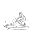
図1は、本発明の実施の形態に係る水上小型推進艇の外観図である。
デッキ1およびハル2を接合して形成した船体3の中央上部にハンドル4が取付けられる。このハンドル4を操縦する運転者の手首にはこの運転者の識別情報(ID情報)が入力されたトランスポンダ5が例えばリストバンド等を用いて装着される。このトランスポンダ5に対し照合信号電波を送受信するためのアンテナ6がハンドル4の取付け部となるウレタン等の軟質材料からなるステアリング軸収納部7内に設けられる。このアンテナ6を介して運転者の照合信号を送受信し運転者を照合するための識別装置8が船体3内に設けられる。
【0016】
これらの運転者側に装着されたトランスポンダ5と船体側に設けられたアンテナ6および識別装置8により後述のように本発明のエンジン停止装置を構成する。なお、アンテナ6の位置は、ハンドル根元部に限らず、運転者の身体に装着したトランスポンダ5に対し送受信機の出力を考慮して送受信可能な船体内の適当な位置に設けることができる。また、トランスポンダ5に対し送受信可能な範囲は、運転者が乗船している状態では腕を上げる等どのような姿勢であっても電波が届くものとし、且つ後述のように運転者が落水したときに直ちにこれを検出できるようにできる限り狭い範囲となるように送受信機の出力を設定する。
【0017】
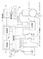
図2は、本発明の実施の形態に係るエンジン停止装置の構成図である。
船体内にエンジン9が搭載される。このエンジン9はスタータモータ10により始動される。スタータモータ10は、スタータリレー11を介して船内に搭載されたバッテリ12に接続されるとともにスタータボタン13に接続される。エンジン9は、点火装置14により点火コイル15を作動させることにより点火駆動される。点火装置14には手動ストップスイッチ15が接続され、必要に応じて手動でエンジンを停止することができる。
【0018】
前述の図1で説明したように、船体内に設けたアンテナ6に接続して識別装置8が設けられる。この識別装置8は、アンテナ6を介して照合電波を送受信するための送受信機16と、送受信する照合電波を解析処理する照合回路17と、照合回路17の処理結果に基づいてエンジンを駆動するための制御回路18とにより構成される。照合回路17(または制御回路18)は、予め登録された識別情報を格納した記憶回路を有し、トランスポンダ5への照合信号を送出するとともにその応答信号の有無を確認し登録された識別情報と照合する。
【0019】
制御回路18は、バッテリ12、スタータボタン13および点火装置14に接続され、照合回路17の照合結果に応じて、エンジン9を始動可能な状態とさせあるいは停止させる。エンジン9が始動可能な状態となれば、スタータボタン13を押すことによりエンジン9を始動させることができる。この制御回路18は、エンジン9の運転制御を行うために元々備っているECU(エンジン制御装置)を用いて照合判断のルーチンを追加して構成してもよい。また、エンジン始動時に電源を投入するためのメインスイッチ19を制御回路18とバッテリ12間に設けた構成としてもよい。このメインスイッチ19は省略した構成でもよい。
次に上記構成のエンジン停止装置の動作について説明する。
まず、運転者がIDタグ(トランスポンダ5)を身体(例えば図1のように手首)に装着して乗船する。次にこの運転者がスタータボタン13を押す。これにより、識別装置8の電源がオンになる。続いて、照合回路17から送受信機16およびアンテナ6を介して質問電波(照合信号)が発信され、トランスポンダ5に対し応答動作に必要なエネルギーを与える。トランスポンダ5は、電磁誘導の原理により電力を得て、予め入力されているIDデータ(識別情報)を応答信号として返信する。識別装置8がこのIDデータをアンテナ6を介して受信する。受信したIDデータは、照合回路17により予め登録してある情報と一致するかどうかが判別される。照合結果が登録してある情報と一致すれば、制御回路18により、スタータリレー11および点火装置14への電源をオンにする。なお、複数の識別情報を登録しておくことにより、複数人による利用が可能になる。
【0020】
ここで運転者が再びスタータボタン13を押すことにより(又は押し続けることにより)、スタータモータ10が駆動されるとともに点火コイルが動作してエンジン9が始動する。
【0021】
一方、受信したIDデータが登録してある情報と一致しない場合には、スタータリレー11および点火装置14の電源がオンにならず、オフ状態のままとなって、エンジン9は始動しない。
【0022】
なお、メインスイッチ19が備る場合には、メインスイッチ19をオンにしたときに、識別装置8の電源をオンにして照合動作を開始するように構成してもよい。
【0023】
エンジン始動後の走行中は、照合回路17は常時一定周期で質問電波をトランスポンダ5に対し送信し、トランスポンダ5からの応答信号を受信する。この走行中に運転者が船体から落水すると、トランスポンダ5が運転者の身体に装着されているため、船体から離れて電波が届かなくなり、応答信号が受信されなくなる。このように照合回路17がトランスポンダ5からの応答信号がないことを検出すると、制御回路18は、点火装置14の回路をオフにしてエンジン9を停止させる。これにより、船体は落水した運転者の近くで停止する。
【0024】
運転者が船体に再乗船して、スタータボタン13を押すことにより、前述と同様の動作が繰り返されエンジン9が始動して走行状態となる。
【0025】
【発明の効果】
以上説明したように、本発明では、識別情報が入力されたトランスポンダが運転者側に保持されるため、ランヤードコード等の連結コードを用いることなくシンプルな構成で運転者を識別して第三者の無断運転を防止し盗難防止を図ることができる。また、運転者の落水や落車等の緊急時を検出してエンジンを停止することが可能になる。この場合、再乗船あるいは再乗車して運転を再開するときに、コード等を接続する必要がないため、運転再開が容易にできる。
【図面の簡単な説明】
【図1】 本発明が適用される小型水上推進艇の外観図。
【図2】 本発明に係るエンジン停止装置の構成図。
【符号の説明】
1:デッキ、2:ハル、3:船体、4:ハンドル、5:トランスポンダ、
6:アンテナ、7:ステアリング軸収納部、8:識別装置、9:エンジン、
10:スタータモータ、11:スタータリレー、12:バッテリ、
13:スタータボタン、14:点火装置、15:点火コイル、
16:送受信機、17:照合回路、18:制御回路、19:メインスイッチ[0001]
BACKGROUND OF THE INVENTION
The present invention relates to an engine stop device, and more particularly to an engine stop device for preventing theft of a small vehicle equipped with an engine such as a small propulsion boat or a snow vehicle and for stopping the engine in an emergency.
[0002]
[Prior art]
For small water vehicles such as water motorcycles and small snow vehicles such as snowmobiles, an engine emergency stop stop switch is used as an engine stop device to stop the engine when the driver falls outside or outside the ship. A lanyard cord coupled to the stop switch is used. One end of this lanyard cord is attached to the driver's wrist, for example, and the other end is provided with a bifurcated locking claw. The locking claw sandwiches the drive projection of the engine stop switch, and the switch is deactivated. It keeps driving in a state. When the driver falls outside the vehicle or outside the vehicle and the latching claw of the lanyard cord comes off the stop switch, the switch is activated and the engine stops.
[0003]
In addition, the identification number is stored in the latching claw portion at the tip of the lanyard cord so that the engine can be operated only when the numbers match, so that the engine can be operated when a person other than the specified owner tries to drive. An anti-theft lanyard code is considered to prevent theft without being applied.
[0004]
On the other hand, immobilizers are used as antitheft devices for automobiles. This immobilizer has a configuration in which a transponder storing owner identification information is attached to a key, an antenna is provided on a key cylinder on the vehicle body side, and a verification circuit is connected to the antenna via a transceiver. When the ignition switch is turned with the key, the transponder built in the key is automatically verified. If the transponder of this key does not match the registered identification information, the engine will not start, preventing unauthorized use by a third party and preventing theft.
[0005]
[Problems to be solved by the invention]
However, in the conventional engine stop device using a lanyard cord, it is troublesome to attach the cord to the vehicle body such as the hull or the vehicle body, especially when the driver falls into the water and stops the engine and then reboards. It took time and effort to fit the small locking claw at the end of the cord into the drive projection of the stop switch.
[0006]
Even if a conventional automobile anti-theft immobilizer is applied to a water-propelled boat as an engine stop device, the transponder is built in the key and held on the vehicle body side during operation. This case cannot be dealt with, and it cannot be applied to a small propulsion boat that does not normally have a key switch structure (main switch).
[0007]
The present invention is based on the above-described conventional technology, and prevents unauthorized driving by a third party without using a cord that connects the driver and the vehicle body, and prevents the driver from falling or falling. An object of the present invention is to provide an engine stop device that can detect and stop the engine.
[0008]
[Means for Solving the Problems]
In order to achieve the above object, in the present invention, a vehicle body equipped with an engine, a transponder to which identification information of the driver is input, a verification circuit for identifying the driver based on a response signal from the transponder, and this In the engine stop device provided with a control circuit for driving and controlling the engine based on the result of collation by the collation circuit, the transponder is separated from the vehicle body and is held in a state of being mounted on the driver side. An engine stop device is provided.
[0009]
According to this configuration, since the transponder to which the identification information is input is held on the driver side, the driver is identified with a simple configuration without using a connecting code such as a lanyard code, and unauthorized operation of a third party is performed. To prevent theft. In addition, the engine can be stopped by detecting an emergency such as a driver's falling water or a falling car.
[0010]
“Driving” means that the engine is in operation, not only when the vehicle is actually running (cruising), but also when the vehicle is idling and the vehicle is stopped. Including.
[0011]
In a preferred configuration example, the control circuit is configured to always transmit a verification signal having a constant period to the transponder during operation, and to stop the engine when there is no response signal from the transponder for the verification signal. It is characterized by.
[0012]
According to this configuration, the presence of the driver can be confirmed based on the presence or absence of a response signal from the transponder by transmitting a verification signal from the vehicle body side to the transponder mounted on the driver side at a constant cycle. When there is no response signal from the vehicle, it can be determined that the driver has fallen or the vehicle has been dropped and the engine can be stopped.
[0013]
In a further preferred configuration example, the vehicle main body is a small propulsion boat.
[0014]
According to this configuration, the engine is immediately stopped particularly when the driver falls with a small propulsion boat, so that the hull does not move far away from the dropped position and can be re-embedded easily.
[0015]
DETAILED DESCRIPTION OF THE INVENTION
Embodiments of the present invention will be described below with reference to the drawings.
FIG. 1 is an external view of a water small propulsion boat according to an embodiment of the present invention.
A handle 4 is attached to an upper center portion of a hull 3 formed by joining the
[0016]
The engine stop device of the present invention is configured by the
[0017]
FIG. 2 is a configuration diagram of the engine stop device according to the embodiment of the present invention.
An engine 9 is mounted in the hull. The engine 9 is started by a starter motor 10. The starter motor 10 is connected to a battery 12 mounted on the ship via a
[0018]
As described above with reference to FIG. 1, the identification device 8 is connected to the
[0019]
The
Next, the operation of the engine stop device having the above configuration will be described.
First, a driver mounts an ID tag (transponder 5) on a body (for example, a wrist as shown in FIG. 1). Next, the driver presses the starter button 13. Thereby, the power supply of the identification device 8 is turned on. Subsequently, an interrogation radio wave (verification signal) is transmitted from the verification circuit 17 via the transmitter / receiver 16 and the
[0020]
When the driver presses the starter button 13 again (or continues to press), the starter motor 10 is driven and the ignition coil operates to start the engine 9.
[0021]
On the other hand, if the received ID data does not match the registered information, the
[0022]
In the case where the main switch 19 is provided, when the main switch 19 is turned on, the power of the identification device 8 may be turned on to start the collation operation.
[0023]
During traveling after the engine is started, the verification circuit 17 always transmits an interrogation radio wave to the
[0024]
When the driver re-embarks on the hull and presses the starter button 13, the same operation as described above is repeated, the engine 9 is started, and a running state is entered.
[0025]
【The invention's effect】
As described above, in the present invention, since the transponder to which the identification information is input is held on the driver side, the driver is identified with a simple configuration without using a connection code such as a lanyard code. It is possible to prevent unauthorized operation and prevent theft. In addition, the engine can be stopped by detecting an emergency such as a driver's falling water or a falling car. In this case, it is not necessary to connect a cord or the like when restarting after reboarding or reboarding, so that restarting of the driving can be facilitated.
[Brief description of the drawings]
FIG. 1 is an external view of a small watercraft to which the present invention is applied.
FIG. 2 is a configuration diagram of an engine stop device according to the present invention.
[Explanation of symbols]
1: Deck, 2: Hull, 3: Hull, 4: Handle, 5: Transponder,
6: Antenna, 7: Steering shaft storage part, 8: Identification device, 9: Engine,
10: Starter motor, 11: Starter relay, 12: Battery,
13: Starter button, 14: Ignition device, 15: Ignition coil,
16: transceiver, 17: verification circuit, 18: control circuit, 19: main switch
Claims (1)
前記制御回路は、前記乗物本体が走行中前記トランスポンダに対し常時一定周期の照合信号を送信し、この照合信号に対するトランスポンダからの応答信号がないときにエンジンを停止するように構成され、
前記乗物本体は、鞍乗車両であることを特徴とするエンジン停止装置。A vehicle body equipped with an engine, a transponder to which driver identification information is input, a verification circuit for identifying a driver based on a response signal from the transponder, and driving the engine based on a verification result of the verification circuit In the engine stop device comprising a control circuit for controlling, the transponder is configured to be separated from the vehicle main body and held in a state of being attached to a driver's body,
The control circuit is configured to always send a verification signal of a constant period to the transponder while the vehicle body is traveling, and to stop the engine when there is no response signal from the transponder for the verification signal,
The engine stop device, wherein the vehicle main body is a saddle riding vehicle.
Priority Applications (3)
| Application Number | Priority Date | Filing Date | Title |
|---|---|---|---|
| JP20059199A JP4205261B2 (en) | 1999-07-14 | 1999-07-14 | Engine stop device |
| US09/615,702 US6404071B1 (en) | 1999-07-14 | 2000-07-13 | Engine stopping apparatus |
| EP20000115246 EP1069012A3 (en) | 1999-07-14 | 2000-07-13 | Engine stopping apparatus |
Applications Claiming Priority (1)
| Application Number | Priority Date | Filing Date | Title |
|---|---|---|---|
| JP20059199A JP4205261B2 (en) | 1999-07-14 | 1999-07-14 | Engine stop device |
Publications (2)
| Publication Number | Publication Date |
|---|---|
| JP2001027137A JP2001027137A (en) | 2001-01-30 |
| JP4205261B2 true JP4205261B2 (en) | 2009-01-07 |
Family
ID=16426907
Family Applications (1)
| Application Number | Title | Priority Date | Filing Date |
|---|---|---|---|
| JP20059199A Expired - Lifetime JP4205261B2 (en) | 1999-07-14 | 1999-07-14 | Engine stop device |
Country Status (3)
| Country | Link |
|---|---|
| US (1) | US6404071B1 (en) |
| EP (1) | EP1069012A3 (en) |
| JP (1) | JP4205261B2 (en) |
Cited By (4)
| Publication number | Priority date | Publication date | Assignee | Title |
|---|---|---|---|---|
| WO2021251367A1 (en) | 2020-06-10 | 2021-12-16 | 日本発條株式会社 | Automatic ship maneuvering system, ship control device, ship control method, and program |
| WO2021251388A1 (en) | 2020-06-10 | 2021-12-16 | 日本発條株式会社 | Automatic ship handling system, ship control device, ship control method, and program |
| WO2021251380A1 (en) | 2020-06-10 | 2021-12-16 | 日本発條株式会社 | Ship control system, ship control method, program and vehicle control system |
| WO2021251382A1 (en) | 2020-06-10 | 2021-12-16 | 日本発條株式会社 | Ship, ship control device, ship control method, and program |
Families Citing this family (16)
| Publication number | Priority date | Publication date | Assignee | Title |
|---|---|---|---|---|
| GB2382441A (en) * | 2001-11-24 | 2003-05-28 | Roke Manor Research | Theft deterrent system |
| JP4301869B2 (en) | 2003-06-06 | 2009-07-22 | ヤマハ発動機株式会社 | Small planing boat |
| JP2005269472A (en) | 2004-03-22 | 2005-09-29 | Yamaha Marine Co Ltd | Control device of small ship |
| JP2006213450A (en) * | 2005-02-03 | 2006-08-17 | Nippon Yusoki Co Ltd | Reach type forklift |
| JP2006321453A (en) | 2005-05-20 | 2006-11-30 | Yamaha Motor Co Ltd | Vehicle control device for saddle riding type vehicle |
| JP2006321452A (en) | 2005-05-20 | 2006-11-30 | Yamaha Motor Co Ltd | Vehicle control device for saddle riding type vehicle |
| JP2006321454A (en) | 2005-05-20 | 2006-11-30 | Yamaha Motor Co Ltd | Vehicle control device for saddle riding type vehicle |
| US7518489B2 (en) * | 2006-01-19 | 2009-04-14 | Honda Motor Co., Ltd. | Method and system for remote immobilization of vehicles |
| US20070208491A1 (en) * | 2006-03-01 | 2007-09-06 | Miller Bruce D | Wireless security and monitoring system for mechanized equipment |
| US20070241862A1 (en) * | 2006-04-12 | 2007-10-18 | Dimig Steven J | Transponder authorization system and method |
| GB2444967A (en) | 2006-06-20 | 2008-06-25 | Vision Eng | Marine safety system |
| JP5081103B2 (en) * | 2008-08-22 | 2012-11-21 | ヤマハ発動機株式会社 | Ship theft deterrent device and ship equipped with the same |
| JP5929010B2 (en) * | 2011-05-23 | 2016-06-01 | 日産自動車株式会社 | Vehicle remote control device |
| TWI657947B (en) * | 2017-06-08 | 2019-05-01 | 宏碁股份有限公司 | On-board unit and method for operating the same, corresponding transportation and method for operating transportation anti-thief system |
| US10566685B2 (en) * | 2017-09-15 | 2020-02-18 | Cnh Industrial America Llc | Integrated mounting for vehicle immobilizer system antenna |
| US11250653B2 (en) * | 2019-02-13 | 2022-02-15 | Brunswick Corporation | Configurable remote control system and method for a marine vessel |
Family Cites Families (16)
| Publication number | Priority date | Publication date | Assignee | Title |
|---|---|---|---|---|
| JPS61291297A (en) * | 1985-06-19 | 1986-12-22 | Sanshin Ind Co Ltd | Remote steering device of vessel |
| US4674454A (en) * | 1985-08-22 | 1987-06-23 | Donald Phairr | Remote control engine starter |
| GB2233487A (en) * | 1988-06-06 | 1991-01-09 | Shurlok Detector Company | Vehicle protection system |
| US4946411A (en) * | 1988-10-20 | 1990-08-07 | Novey Richard T | Hand held remote control for outboard powerheads |
| NO921830D0 (en) * | 1992-05-08 | 1992-05-08 | Defa Electronic As | DEVICE FOR ALARM SYSTEMS, SPECIAL CAR ALARM SYSTEMS |
| US5349329B1 (en) * | 1993-05-07 | 1996-09-10 | Ideaz International Inc | Vehicle security apparatus and method |
| US5394820A (en) * | 1993-11-29 | 1995-03-07 | Dach; Samuel | Motorized water vehicle |
| US5592169A (en) * | 1993-12-24 | 1997-01-07 | Mitsui Kinzoku Kogyo Kabushiki Kaisha | Transmitter for vehicle remote control system |
| US5459448A (en) * | 1994-06-27 | 1995-10-17 | Dortenzio; Christopher J. | Automotive continuous protection anti-theft system |
| US5486806A (en) * | 1994-11-09 | 1996-01-23 | Firari; Harold A. | Anti-hijacking and theft prevention device for motor vehicles |
| US5942988A (en) * | 1995-09-15 | 1999-08-24 | Bulldog Security Alarm Systems | Remote engine starter with engine cutoff |
| US6116201A (en) * | 1995-12-22 | 2000-09-12 | Labken, Inc. | In-solenoid chip for undertaking plural functions |
| WO1997039924A1 (en) * | 1996-04-24 | 1997-10-30 | Steve Murray | Radio controlled engine kill switch |
| US5794580A (en) * | 1997-02-26 | 1998-08-18 | Remote Products Inc. | Remote start/stop system for magneto ignition engines |
| US6091340A (en) * | 1997-11-25 | 2000-07-18 | Lee; Brian | Remote on/off disable parts and system |
| US6072248A (en) * | 1998-08-05 | 2000-06-06 | Muise; Christopher Russel | Method of and system for externally and remotely disabling stolen or unauthorized operated vehicles by pursuing police and the like |
-
1999
- 1999-07-14 JP JP20059199A patent/JP4205261B2/en not_active Expired - Lifetime
-
2000
- 2000-07-13 US US09/615,702 patent/US6404071B1/en not_active Expired - Lifetime
- 2000-07-13 EP EP20000115246 patent/EP1069012A3/en not_active Withdrawn
Cited By (4)
| Publication number | Priority date | Publication date | Assignee | Title |
|---|---|---|---|---|
| WO2021251367A1 (en) | 2020-06-10 | 2021-12-16 | 日本発條株式会社 | Automatic ship maneuvering system, ship control device, ship control method, and program |
| WO2021251388A1 (en) | 2020-06-10 | 2021-12-16 | 日本発條株式会社 | Automatic ship handling system, ship control device, ship control method, and program |
| WO2021251380A1 (en) | 2020-06-10 | 2021-12-16 | 日本発條株式会社 | Ship control system, ship control method, program and vehicle control system |
| WO2021251382A1 (en) | 2020-06-10 | 2021-12-16 | 日本発條株式会社 | Ship, ship control device, ship control method, and program |
Also Published As
| Publication number | Publication date |
|---|---|
| JP2001027137A (en) | 2001-01-30 |
| EP1069012A2 (en) | 2001-01-17 |
| EP1069012A3 (en) | 2003-07-02 |
| US6404071B1 (en) | 2002-06-11 |
Similar Documents
| Publication | Publication Date | Title |
|---|---|---|
| JP4205261B2 (en) | Engine stop device | |
| JP4476062B2 (en) | In-vehicle control device | |
| JP4181198B2 (en) | Vehicle theft prevention system and vehicle theft prevention method | |
| US7477136B2 (en) | Theft deterrent system and method for a vehicle | |
| JP4121345B2 (en) | Electronic key system for vehicles | |
| JP4329945B2 (en) | Engine start system | |
| US7423353B2 (en) | Vehicle anti-theft system | |
| JP3875706B2 (en) | Engine start system | |
| US7564146B2 (en) | Moving body starting system | |
| JP3589188B2 (en) | Electronic key device for vehicles | |
| US7081028B1 (en) | Portable control device used as a security and safety component of a marine propulsion system | |
| JP2970642B2 (en) | In-vehicle remote control device | |
| JP4144741B2 (en) | Vehicle anti-theft device | |
| JP3799961B2 (en) | Electronic key device for vehicle | |
| EP1067028A2 (en) | Security apparatus for vehicle | |
| JP3930386B2 (en) | Electronic key system | |
| JP4173983B2 (en) | Electronic key system for motorcycles | |
| JP4350114B2 (en) | Propeller anti-theft device | |
| JP2000329041A (en) | Engine starting control device | |
| JP2710970B2 (en) | Vehicle anti-theft device | |
| JP2597173B2 (en) | Vehicle anti-theft device | |
| JP3965349B2 (en) | Electronic key system for vehicles | |
| JP4318150B2 (en) | Preventing forgetting to remove key of motorcycle | |
| JP3552557B2 (en) | Vehicle remote control device | |
| JP4313505B2 (en) | Remote control device for vehicle |
Legal Events
| Date | Code | Title | Description |
|---|---|---|---|
| RD03 | Notification of appointment of power of attorney |
Free format text: JAPANESE INTERMEDIATE CODE: A7423 Effective date: 20060628 |
|
| A621 | Written request for application examination |
Free format text: JAPANESE INTERMEDIATE CODE: A621 Effective date: 20060712 |
|
| A131 | Notification of reasons for refusal |
Free format text: JAPANESE INTERMEDIATE CODE: A131 Effective date: 20080415 |
|
| A521 | Written amendment |
Free format text: JAPANESE INTERMEDIATE CODE: A523 Effective date: 20080613 |
|
| A131 | Notification of reasons for refusal |
Free format text: JAPANESE INTERMEDIATE CODE: A131 Effective date: 20080715 |
|
| A521 | Written amendment |
Free format text: JAPANESE INTERMEDIATE CODE: A523 Effective date: 20080820 |
|
| TRDD | Decision of grant or rejection written | ||
| A01 | Written decision to grant a patent or to grant a registration (utility model) |
Free format text: JAPANESE INTERMEDIATE CODE: A01 Effective date: 20080916 |
|
| A01 | Written decision to grant a patent or to grant a registration (utility model) |
Free format text: JAPANESE INTERMEDIATE CODE: A01 |
|
| A61 | First payment of annual fees (during grant procedure) |
Free format text: JAPANESE INTERMEDIATE CODE: A61 Effective date: 20081016 |
|
| FPAY | Renewal fee payment (event date is renewal date of database) |
Free format text: PAYMENT UNTIL: 20111024 Year of fee payment: 3 |
|
| R150 | Certificate of patent or registration of utility model |
Ref document number: 4205261 Country of ref document: JP Free format text: JAPANESE INTERMEDIATE CODE: R150 Free format text: JAPANESE INTERMEDIATE CODE: R150 |
|
| FPAY | Renewal fee payment (event date is renewal date of database) |
Free format text: PAYMENT UNTIL: 20111024 Year of fee payment: 3 |
|
| FPAY | Renewal fee payment (event date is renewal date of database) |
Free format text: PAYMENT UNTIL: 20121024 Year of fee payment: 4 |
|
| R250 | Receipt of annual fees |
Free format text: JAPANESE INTERMEDIATE CODE: R250 |
|
| FPAY | Renewal fee payment (event date is renewal date of database) |
Free format text: PAYMENT UNTIL: 20121024 Year of fee payment: 4 |
|
| FPAY | Renewal fee payment (event date is renewal date of database) |
Free format text: PAYMENT UNTIL: 20131024 Year of fee payment: 5 |
|
| R250 | Receipt of annual fees |
Free format text: JAPANESE INTERMEDIATE CODE: R250 |
|
| R250 | Receipt of annual fees |
Free format text: JAPANESE INTERMEDIATE CODE: R250 |
|
| R250 | Receipt of annual fees |
Free format text: JAPANESE INTERMEDIATE CODE: R250 |
|
| R250 | Receipt of annual fees |
Free format text: JAPANESE INTERMEDIATE CODE: R250 |
|
| R250 | Receipt of annual fees |
Free format text: JAPANESE INTERMEDIATE CODE: R250 |
|
| R250 | Receipt of annual fees |
Free format text: JAPANESE INTERMEDIATE CODE: R250 |
|
| R250 | Receipt of annual fees |
Free format text: JAPANESE INTERMEDIATE CODE: R250 |
|
| EXPY | Cancellation because of completion of term |