JP4205131B2 - Degassing device - Google Patents
Degassing device Download PDFInfo
- Publication number
- JP4205131B2 JP4205131B2 JP2007009858A JP2007009858A JP4205131B2 JP 4205131 B2 JP4205131 B2 JP 4205131B2 JP 2007009858 A JP2007009858 A JP 2007009858A JP 2007009858 A JP2007009858 A JP 2007009858A JP 4205131 B2 JP4205131 B2 JP 4205131B2
- Authority
- JP
- Japan
- Prior art keywords
- molten metal
- degassing
- opening
- side wall
- chamber
- Prior art date
- Legal status (The legal status is an assumption and is not a legal conclusion. Google has not performed a legal analysis and makes no representation as to the accuracy of the status listed.)
- Active
Links
- 238000007872 degassing Methods 0.000 title claims description 72
- 229910052751 metal Inorganic materials 0.000 claims description 57
- 239000002184 metal Substances 0.000 claims description 57
- 238000003756 stirring Methods 0.000 claims description 17
- XLYOFNOQVPJJNP-UHFFFAOYSA-N water Substances O XLYOFNOQVPJJNP-UHFFFAOYSA-N 0.000 description 27
- 239000007789 gas Substances 0.000 description 10
- 239000011261 inert gas Substances 0.000 description 8
- 229910000838 Al alloy Inorganic materials 0.000 description 4
- 238000005266 casting Methods 0.000 description 2
- 230000000694 effects Effects 0.000 description 2
- 239000000463 material Substances 0.000 description 2
- 241000287463 Phalacrocorax Species 0.000 description 1
- 229910052782 aluminium Inorganic materials 0.000 description 1
- XAGFODPZIPBFFR-UHFFFAOYSA-N aluminium Chemical compound [Al] XAGFODPZIPBFFR-UHFFFAOYSA-N 0.000 description 1
- 230000004048 modification Effects 0.000 description 1
- 238000012986 modification Methods 0.000 description 1
- 238000005192 partition Methods 0.000 description 1
Images

Landscapes
- Manufacture And Refinement Of Metals (AREA)
Description
本発明は、アルミニウム合金などの溶湯の脱ガス処理を行なう脱ガス装置に関する。 The present invention relates to a degassing apparatus for degassing a molten metal such as an aluminum alloy.
アルミニウム合金などの鋳造では、鋳造前に溶湯中のH2ガスや酸化物等の介在物などを除去するため、脱ガス処理を行なう。この脱ガス処理を行なう脱ガス装置(脱ガス炉ともいう。)としては、例えば、溶湯を脱ガス室で脱ガス用攪拌体により回転攪拌してH2ガスや介在物などを除去し、この脱ガスした溶湯を、脱ガス室の底付近に設けた開口部より曲管を経由して流し出し、鋳型に出湯するものがある(下記特許文献1,2参照)。
In casting of an aluminum alloy or the like, a degassing process is performed to remove inclusions such as H 2 gas and oxide in the molten metal before casting. As a degassing apparatus (also referred to as a degassing furnace) for performing this degassing treatment, for example, the molten metal is rotationally stirred by a degassing stirrer in a degassing chamber to remove H 2 gas, inclusions, etc. Some degassed molten metal flows out from an opening provided in the vicinity of the bottom of the degassing chamber via a curved pipe and is discharged into a mold (see
また、溶湯を脱ガス処理槽でガス放出手段により回転攪拌してH2ガスや介在物などを除去し、この脱ガスした溶湯を、仕切板の下方に設けた開口から流し出し、鋳型に出湯するものがある(下記特許文献3参照)。
In addition, the molten metal is rotated and stirred by a gas releasing means in a degassing treatment tank to remove H 2 gas and inclusions, and the degassed molten metal is poured out from an opening provided below the partition plate and discharged into a mold. (See
しかし、上記特許文献1〜3に記載の脱ガス装置では、溶湯中のH2ガスや介在物などが十分に除去できないことがあった。
本発明者は、これらの原因を究明したところ、脱ガス室(又は脱ガス処理槽)の底付近に溶湯を流し出す開口(又は曲管)が設けてあると、攪拌されずに流れ出る溶湯があり、H2ガス(又は吹き込んだ不活性ガス)が溶湯中に残留してしまうためであることが解かった。
また、曲管が底付近に配してあると、乱流を起こし、介在物が溶湯中に混入しやすいことが解かった。
However, in the degassing apparatuses described in Patent Documents 1 to 3, H 2 gas and inclusions in the molten metal may not be sufficiently removed.
As a result of investigating these causes, the present inventor found that if an opening (or a curved pipe) through which the molten metal flows out was provided near the bottom of the degassing chamber (or degassing treatment tank), the molten metal flowing out without stirring would be There, it H 2 gas (or sparged inert gas) is for cormorants want remaining in the molten metal was Tsu solved.
Further, it was found that when the bent pipe is arranged near the bottom, turbulence is caused and inclusions are easily mixed into the molten metal.
そこで、本発明の目的は、溶湯中のH2ガスや介在物などの除去を十分に行なうことができる脱ガス装置を提供することにある。 Therefore, an object of the present invention is to provide a degassing apparatus that can sufficiently remove H 2 gas, inclusions, and the like in a molten metal.
本発明の脱ガス装置は、溶湯を攪拌体により回転攪拌して脱ガスをする脱ガス室を備えた脱ガス装置において、脱ガス室から溶湯を流し出す開口部を側壁の下方付近に設け、脱ガス室の底面に該開口部を囲う囲い板を、回流する溶湯の下流側を開放させて配したことを特徴とするものである。 The degassing apparatus of the present invention is a degassing apparatus having a degassing chamber for degassing by rotating and stirring the molten metal with a stirring body, and an opening for flowing the molten metal from the degassing chamber is provided near the lower side of the side wall. A shroud surrounding the opening is disposed on the bottom surface of the degassing chamber with the downstream side of the circulating molten metal being opened.
このようにすることにより、開口部の周囲に囲い板を設けたため、底の方にある溶湯は、攪拌されずに流れ出ることがなく、脱ガスを十分に行なうことができ、また、介在物も十分に除去できる。 In this way, since the enclosure plate is provided around the opening, the molten metal at the bottom can be sufficiently degassed without flowing out without being stirred, and the inclusions Can be removed sufficiently.
前記囲い板は、高さを、前記開口部の高さよりも高くするのがよく、これにより、溶湯が攪拌されずに流れ出ることをより防止できる。
前記脱ガス装置は、脱ガス室を、上面視略正方形状に形成し、前記開口部を、一側壁の下方中央付近に設け、囲い板を、上面視略L字状に形成することができる。
このように脱ガス室を上面視略正方形状に形成し、開口部を一側壁の下方中央付近に設けることにより、乱流を防ぐことができる。
The height of the enclosure plate is preferably higher than the height of the opening, thereby preventing the molten metal from flowing out without stirring.
In the degassing apparatus, the degassing chamber can be formed in a substantially square shape when viewed from above, the opening can be provided near the lower center of one side wall, and the surrounding plate can be formed in a substantially L shape when viewed from above. .
As described above, the degassing chamber is formed in a substantially square shape when viewed from above, and the opening is provided near the lower center of the one side wall, thereby preventing turbulent flow.
なお、本発明において、「回流する溶湯の下流側」とは、攪拌体の回転軸と開口部との間の溶湯の流れの下手側の意である。 In the present invention, the “downstream side of the circulating molten metal” means the lower side of the molten metal flow between the rotating shaft of the stirring member and the opening.
以下、本発明の一実施形態を、図面を用いて説明する。
図1は本発明の一実施形態の脱ガス装置の斜視図、図2は図1の装置の上面図、図3は図1の装置の側断面図である。
Hereinafter, an embodiment of the present invention will be described with reference to the drawings.
1 is a perspective view of a degassing apparatus according to an embodiment of the present invention, FIG. 2 is a top view of the apparatus of FIG. 1, and FIG. 3 is a side sectional view of the apparatus of FIG.
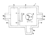
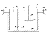
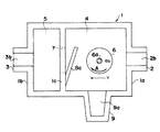
本発明の一実施形態の脱ガス装置1は、図1〜3に示すように、周囲に側壁を設けた略直方体状の槽であり、長手方向の一側壁1aに入湯口2を設け、この側壁1aに対向する側壁1bに出湯口3を設けてあり、槽内は、側壁1aと並行する側壁1cで仕切られ、入湯口2側を脱ガス室4、出湯口3側を出湯室5とし、脱ガス室4の容量を、出湯室5の容量よりも大きく形成してある。
As shown in FIGS. 1 to 3, the degassing apparatus 1 according to an embodiment of the present invention is a substantially rectangular parallelepiped tank provided with a side wall around it, and a
脱ガス室4は、入湯口2から入湯されたアルミニウム合金などの溶湯を、貯留し、室内に配してある攪拌体6で回転攪拌させ、不活性ガスを送り込んでH2ガスなどを脱ガスし、側壁1cの下方に設けた開口部7から流し出す箇所である。
本実施形態では、脱ガス室4を、上面視略正方形状に形成してあり、このようにすれば、溶湯の滞留時間が均等なものとなり、不活性ガスを均質に分散させることができる。脱ガス室4を、上面視略真円の円筒状に形成しても同様の効果が得られる。
The
In the present embodiment, the
入湯口2は、側壁1aの上方略中央から外方に突出するように形成してあり、この上面2aには溝2bを形成し、溶湯を脱ガス室4内に入湯できるようにしてある。
The
攪拌体6は、円盤形状としてあり、この略中心に、上方に伸びた軸部6aを設け、これを回転軸として回転し、溶湯を攪拌するようにしてある。軸部6aは、円筒状に形成してあり、この内部6bを、不活性ガスが通り、軸部6aの先端から不活性ガスを溶湯中に放出させるようにしてある。
攪拌体6は、脱ガス室4の略中心に配するのが好ましい。
The
The
開口部7は、側壁1cの下方中央付近に設けた略矩形状の孔であり、脱ガス室4と出湯室5とを連結し、溶湯を脱ガス室4から出湯室5に流し出す箇所である。開口部7の上限は、脱ガス室4の底面から攪拌体6の下面までの間に位置していることが好ましい。開口部7の下限は、脱ガス室4の底面4aと略同じ高さや脱ガス室4の底面4aから5〜10mm程度の高さなどとすることが好ましい。底面4aと略同じ高さにすると、脱ガス室4の溶湯の掃除がしやすくなり、底面4aから5〜10mm程度の高さにすると、沈んだ介在物が溶湯中に混入しにくくなる。
また、開口部7は、側壁1cの幅を4等分した時に、その中央の2つ幅分に形成することが好ましい。
The
Moreover, it is preferable that the
開口部7の脱ガス室4側の周囲には、上面視略L字形状の囲い板8が、底面4aから上方に突出するように形成してある。囲い板8は、溶湯が回流せずに出湯室5に流れ込むことを防止するため、回流する溶湯の流れの上手側を閉塞し、下手側を開放するように配してある。つまり、図2に示すように、攪拌体6が、矢印Aの方向に回転している場合、溶湯もこれと同じ方向に回転する。そうすると、攪拌体6の回転軸6aと側壁1cとの間の溶湯の流れは、図2の下側から上側への流れになるため、この場合、囲い板8は、図2の下側が閉塞し、上側が開放するように配する。
囲い板8の高さは、特に限定するものではないが、開口部7の高さよりも高くするのが好ましく、具体的には、開口部7の上限よりも10〜20mm高くするのが好ましい。
囲い板8の少なくとも一面は、開口部7に向かう攪拌体6の回転の接線方向(図2のX方向)に対して、90°±25°の角度にするのが好ましく、特に80°以上にするのが好ましい。本実施形態では90°にしてある。これにより、滞留時間の短い溶湯が開口部7より、流出するのを防止することができる。
本実施形態では、囲い板8は、上面視略L字形状に形成したが、これに限定するものではなく、図4に示すように、平板の囲い板8aを傾斜状に配してもよく、この場合、囲い板8の一面は、開口部7に向かう攪拌体6の回転の接線方向(図4のY方向)に対して、70°の角度にしてある。
Around the
The height of the surrounding
At least one surface of the
In the present embodiment, the surrounding
出湯室5は、脱ガス室4から流れ込んできた溶湯を貯留し、出湯口3から鋳型(図示せず)などに流し込む箇所である。
The
出湯口3は、装置1の側面1bの上方略中央から外方に突出するように形成してあり、この上面3aには溝3bを形成してあり、溶湯を鋳型などに出湯できるようにしてある。
The
なお、図2に示す、符号9は、そうじ口であり、この内側を脱ガス室4と連なるように適宜深さに凹まして凹部9aを形成し、ここに浮遊した介在物などを集め、除去することができる。
In addition, the code |
上記装置1は、入湯口2から溶湯を脱ガス室4に流し込み、貯留し、攪拌体6により溶湯を回転攪拌させつつ、不活性ガスを放出して脱ガスする。この際、出湯室5と連結した開口部7の周囲には囲い板8を設けてあるため、溶湯が攪拌されずに流れ出ることがなく、溶湯の脱ガスを十分に行なうことができる。
アルミニウム溶湯を装置1に流し込んだ場合は、流入量と流出量のバランスを取り、脱ガス室4内の滞留時間を5〜10分にすることが好ましい。
In the apparatus 1, the molten metal is poured into the
When the molten aluminum is poured into the apparatus 1, it is preferable to balance the inflow amount and the outflow amount and set the residence time in the
また、従来では、脱ガス室5の底面に曲管などを配することがあり、溶湯が乱流を起こし、H2ガスや介在物などが溶湯中に混入してしまうことがあったが、本発明では、溶湯が乱流を起こすことがなく、H2ガスや介在物などが溶湯中に混入しにくくなる。
In addition, conventionally, a bent pipe or the like may be disposed on the bottom surface of the
なお、本実施形態では、出湯室を設けた脱ガス装置としてあるが、これに限定するものではなく、脱ガス室が連続した二槽式などにすることもできる。 In the present embodiment, the degassing apparatus is provided with a hot water discharge chamber, but the present invention is not limited to this, and a two-tank type with continuous degassing chambers may be used.
次に、本発明の他の実施形態を、図面を用いて説明する。なお、上記実施形態と同一名称の部位は、上記と同様な構成ともすることができ、同様な作用効果を有するものである。
図5は本発明の他の実施形態の脱ガス装置の上面図である。
Next, another embodiment of the present invention will be described with reference to the drawings. In addition, the site | part of the same name as the said embodiment can also be set as the same structure as the above, and has the same effect.
FIG. 5 is a top view of a degassing apparatus according to another embodiment of the present invention.
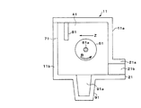
本発明の他の実施形態の脱ガス装置11は、図5に示すように、周囲に側壁を設けた略立方体状の槽であり、一側壁11aに入湯口21を設け、この側壁11aに対向する側壁11bに開口部71を設けてあり、槽内に、攪拌体61を配して脱ガス室41としてある。
As shown in FIG. 5, the degassing apparatus 11 according to another embodiment of the present invention is a substantially cubic tank provided with a side wall around it, and is provided with a
脱ガス室41は、入湯口21から入湯されたアルミニウム合金などの溶湯を、貯留し、室内に配してある攪拌体61で回転攪拌させ、不活性ガスを送り込んで脱ガスし、側壁11bの下方に設けた開口部71から流し出す箇所である。
The
入湯口21は、側壁11aの上方一端側(図5では下側)から外方に突出するように形成してあり、この上面21aには溝21bを形成し、溶湯を脱ガス室41内に入湯できるようにしてある。
The
攪拌体61は、上記実施形態の攪拌体6と同様のものを用いることができる。
The
開口部71は、側壁11bの下方他端側(図5では上側)に設けた略矩形状の孔であり、脱ガス室41から溶湯を流し出せるようにしてある。
The
開口部71の脱ガス室41側の周囲には、矩形板状の囲い板81が、底面41aから上方に突出するように形成してある。囲い板81は、溶湯が回流せずに流れ出ることを防止するため、回流する溶湯の流れの上手側を閉塞し、下手側を開放するように配してある。つまり、図5に示すように、攪拌体61が、矢印Bの方向に回転している場合、溶湯もこれと同じ方向に回転する。そうすると、攪拌体61の軸部61aと側壁11bとの間の溶湯の流れは、図5の上側から下側への流れになるため、この場合、囲い板81は、図5の上側が閉塞し、下側が開放するように配する。
囲い板81の一面は、開口部71に向かう攪拌体61の回転の接線方向(図5のZ方向)に対して、90°の角度にしてある。
A rectangular plate-shaped
One surface of the surrounding
図5に示す、符号91は、そうじ口であり、上記実施態様のそうじ口9と同様に、凹部91aに浮遊した介在物などを集め、除去することができる。
上記装置11は、入湯口21から溶湯を脱ガス室41に流し込み、貯留し、攪拌体61により溶湯を回転攪拌させ、不活性ガスを送り込んで脱ガスする。この際、開口部71の周囲には囲い板81を設けてあるため、溶湯が攪拌されずに流れ出ることがなく、溶湯の脱ガスを十分に行なうことができる。
The apparatus 11 flows the molten metal into the
本実施形態では、入湯口21を側壁11aの上方一端側に設け、開口部71を側壁11bの下方他端側に設けてあり、このように入湯口21と開口部71とを対角線上に設けてあるので溶湯の攪拌時間が長くなり、脱ガスを十分に行なうことができる。
In the present embodiment, the
なお、図1〜5に示した装置は、本発明の特徴を理解しやすくするため、蓋材を省略して記載してあり、本来では、上方を蓋材で覆い使用するものである。 In addition, in order to make it easy to understand the features of the present invention, the apparatus shown in FIGS. 1 to 5 is described with the lid material omitted, and is originally used by covering the top with the lid material.
1脱ガス装置
1a側壁
1b側壁
1c側壁
2入湯口
2a上面
2b溝
3出湯口
3a上面
3b溝
4脱ガス室
4a底面
5出湯室
6攪拌体
6a回転軸
6b内部
7開口部
8,8a囲い板
9そうじ口
9a凹部
DESCRIPTION OF SYMBOLS 1 Degassing apparatus
Claims (4)
Priority Applications (3)
| Application Number | Priority Date | Filing Date | Title |
|---|---|---|---|
| JP2007009858A JP4205131B2 (en) | 2007-01-19 | 2007-01-19 | Degassing device |
| PCT/JP2008/000050 WO2008087865A1 (en) | 2007-01-19 | 2008-01-18 | Degassing apparatus |
| CN200880001324XA CN101568397B (en) | 2007-01-19 | 2008-01-18 | Degassing apparatus |
Applications Claiming Priority (1)
| Application Number | Priority Date | Filing Date | Title |
|---|---|---|---|
| JP2007009858A JP4205131B2 (en) | 2007-01-19 | 2007-01-19 | Degassing device |
Publications (3)
| Publication Number | Publication Date |
|---|---|
| JP2008173671A JP2008173671A (en) | 2008-07-31 |
| JP2008173671A5 JP2008173671A5 (en) | 2008-09-11 |
| JP4205131B2 true JP4205131B2 (en) | 2009-01-07 |
Family
ID=39701083
Family Applications (1)
| Application Number | Title | Priority Date | Filing Date |
|---|---|---|---|
| JP2007009858A Active JP4205131B2 (en) | 2007-01-19 | 2007-01-19 | Degassing device |
Country Status (2)
| Country | Link |
|---|---|
| JP (1) | JP4205131B2 (en) |
| CN (1) | CN101568397B (en) |
Families Citing this family (6)
| Publication number | Priority date | Publication date | Assignee | Title |
|---|---|---|---|---|
| JP5444677B2 (en) * | 2008-10-01 | 2014-03-19 | 日本軽金属株式会社 | Molten metal cleaning method and molten metal cleaning apparatus |
| JP5575933B2 (en) * | 2013-01-18 | 2014-08-20 | 昭和電工株式会社 | Aluminum melt treatment equipment |
| CN104073646B (en) * | 2013-03-25 | 2017-08-25 | 三井金属矿业株式会社 | Degasser |
| CN103495709B (en) * | 2013-09-18 | 2015-08-12 | 安徽电气集团股份有限公司 | A kind of High-temperature melt conveyer |
| CN110756750A (en) * | 2019-11-26 | 2020-02-07 | 扬州瑞斯乐复合金属材料有限公司 | Isothermal casting method of wrought aluminum alloy round ingot |
| CN116475365A (en) | 2022-01-13 | 2023-07-25 | 米尼翁大学 | Apparatus for ultrasonic treatment and transfer of molten metal and method thereof |
-
2007
- 2007-01-19 JP JP2007009858A patent/JP4205131B2/en active Active
-
2008
- 2008-01-18 CN CN200880001324XA patent/CN101568397B/en active Active
Also Published As
| Publication number | Publication date |
|---|---|
| CN101568397B (en) | 2011-05-11 |
| JP2008173671A (en) | 2008-07-31 |
| CN101568397A (en) | 2009-10-28 |
Similar Documents
| Publication | Publication Date | Title |
|---|---|---|
| JP4205131B2 (en) | Degassing device | |
| JP6261087B2 (en) | Scrap settling system | |
| US7497988B2 (en) | Vortexer apparatus | |
| WO2010032550A1 (en) | Melt refiner | |
| JP4419934B2 (en) | Method for continuous casting of molten metal | |
| JP4602241B2 (en) | Submerged stirring device | |
| JP3631999B2 (en) | Fine bubble feeder | |
| JP4570050B2 (en) | Convection inducing device in tank | |
| JP2008173671A5 (en) | ||
| JP6261387B2 (en) | Degassing device | |
| JP4183732B1 (en) | Degassing device | |
| JP2001198444A (en) | Stirring apparatus | |
| JPH0563529B2 (en) | ||
| KR101167083B1 (en) | Fin baffle and agitating vessel having the same | |
| JP4333430B2 (en) | Slurry agitator | |
| JP4817928B2 (en) | Impeller and underwater mixer | |
| JP7548548B2 (en) | Agitation rotor and liquid treatment device | |
| JP2007204843A (en) | Nozzle device for blowing gas, and gas-blowing facility provided with the same | |
| JP3216255U (en) | Water treatment device with overflow wall | |
| JP4538479B2 (en) | Floatator | |
| JP2020069484A (en) | Holding furnace | |
| JP2010247112A (en) | Agitator | |
| JP2024076500A (en) | Agitation device | |
| JP2010223436A (en) | Agitating body for molten metal | |
| JP2010236784A (en) | Baffle member and degassing device including the same |
Legal Events
| Date | Code | Title | Description |
|---|---|---|---|
| A521 | Request for written amendment filed |
Free format text: JAPANESE INTERMEDIATE CODE: A523 Effective date: 20080619 |
|
| A621 | Written request for application examination |
Free format text: JAPANESE INTERMEDIATE CODE: A621 Effective date: 20080619 |
|
| A871 | Explanation of circumstances concerning accelerated examination |
Free format text: JAPANESE INTERMEDIATE CODE: A871 Effective date: 20080619 |
|
| A975 | Report on accelerated examination |
Free format text: JAPANESE INTERMEDIATE CODE: A971005 Effective date: 20080807 |
|
| A131 | Notification of reasons for refusal |
Free format text: JAPANESE INTERMEDIATE CODE: A131 Effective date: 20080819 |
|
| A521 | Request for written amendment filed |
Free format text: JAPANESE INTERMEDIATE CODE: A523 Effective date: 20080904 |
|
| TRDD | Decision of grant or rejection written | ||
| A01 | Written decision to grant a patent or to grant a registration (utility model) |
Free format text: JAPANESE INTERMEDIATE CODE: A01 Effective date: 20081007 |
|
| A01 | Written decision to grant a patent or to grant a registration (utility model) |
Free format text: JAPANESE INTERMEDIATE CODE: A01 |
|
| A61 | First payment of annual fees (during grant procedure) |
Free format text: JAPANESE INTERMEDIATE CODE: A61 Effective date: 20081015 |
|
| FPAY | Renewal fee payment (event date is renewal date of database) |
Free format text: PAYMENT UNTIL: 20111024 Year of fee payment: 3 |
|
| R150 | Certificate of patent or registration of utility model |
Ref document number: 4205131 Country of ref document: JP Free format text: JAPANESE INTERMEDIATE CODE: R150 Free format text: JAPANESE INTERMEDIATE CODE: R150 |
|
| FPAY | Renewal fee payment (event date is renewal date of database) |
Free format text: PAYMENT UNTIL: 20121024 Year of fee payment: 4 |
|
| FPAY | Renewal fee payment (event date is renewal date of database) |
Free format text: PAYMENT UNTIL: 20131024 Year of fee payment: 5 |
|
| R250 | Receipt of annual fees |
Free format text: JAPANESE INTERMEDIATE CODE: R250 |
|
| R250 | Receipt of annual fees |
Free format text: JAPANESE INTERMEDIATE CODE: R250 |
|
| R250 | Receipt of annual fees |
Free format text: JAPANESE INTERMEDIATE CODE: R250 |
|
| R250 | Receipt of annual fees |
Free format text: JAPANESE INTERMEDIATE CODE: R250 |
|
| R250 | Receipt of annual fees |
Free format text: JAPANESE INTERMEDIATE CODE: R250 |
|
| R250 | Receipt of annual fees |
Free format text: JAPANESE INTERMEDIATE CODE: R250 |
|
| R250 | Receipt of annual fees |
Free format text: JAPANESE INTERMEDIATE CODE: R250 |
|
| R250 | Receipt of annual fees |
Free format text: JAPANESE INTERMEDIATE CODE: R250 |
|
| R250 | Receipt of annual fees |
Free format text: JAPANESE INTERMEDIATE CODE: R250 |
|
| R250 | Receipt of annual fees |
Free format text: JAPANESE INTERMEDIATE CODE: R250 |
|
| R250 | Receipt of annual fees |
Free format text: JAPANESE INTERMEDIATE CODE: R250 |
|
| R250 | Receipt of annual fees |
Free format text: JAPANESE INTERMEDIATE CODE: R250 |
|
| R250 | Receipt of annual fees |
Free format text: JAPANESE INTERMEDIATE CODE: R250 |