JP4204475B2 - Methods for installing high or medium power cables in the ground - Google Patents
Methods for installing high or medium power cables in the ground Download PDFInfo
- Publication number
- JP4204475B2 JP4204475B2 JP2003553682A JP2003553682A JP4204475B2 JP 4204475 B2 JP4204475 B2 JP 4204475B2 JP 2003553682 A JP2003553682 A JP 2003553682A JP 2003553682 A JP2003553682 A JP 2003553682A JP 4204475 B2 JP4204475 B2 JP 4204475B2
- Authority
- JP
- Japan
- Prior art keywords
- cable
- installation duct
- duct
- installation
- fluid
- Prior art date
- Legal status (The legal status is an assumption and is not a legal conclusion. Google has not performed a legal analysis and makes no representation as to the accuracy of the status listed.)
- Expired - Lifetime
Links
Images


Classifications
-
- H—ELECTRICITY
- H02—GENERATION; CONVERSION OR DISTRIBUTION OF ELECTRIC POWER
- H02G—INSTALLATION OF ELECTRIC CABLES OR LINES, OR OF COMBINED OPTICAL AND ELECTRIC CABLES OR LINES
- H02G1/00—Methods or apparatus specially adapted for installing, maintaining, repairing or dismantling electric cables or lines
- H02G1/06—Methods or apparatus specially adapted for installing, maintaining, repairing or dismantling electric cables or lines for laying cables, e.g. laying apparatus on vehicle
- H02G1/08—Methods or apparatus specially adapted for installing, maintaining, repairing or dismantling electric cables or lines for laying cables, e.g. laying apparatus on vehicle through tubing or conduit, e.g. rod or draw wire for pushing or pulling
-
- E—FIXED CONSTRUCTIONS
- E02—HYDRAULIC ENGINEERING; FOUNDATIONS; SOIL SHIFTING
- E02F—DREDGING; SOIL-SHIFTING
- E02F5/00—Dredgers or soil-shifting machines for special purposes
- E02F5/02—Dredgers or soil-shifting machines for special purposes for digging trenches or ditches
- E02F5/08—Dredgers or soil-shifting machines for special purposes for digging trenches or ditches with digging wheels turning round an axis
-
- E—FIXED CONSTRUCTIONS
- E02—HYDRAULIC ENGINEERING; FOUNDATIONS; SOIL SHIFTING
- E02F—DREDGING; SOIL-SHIFTING
- E02F5/00—Dredgers or soil-shifting machines for special purposes
- E02F5/02—Dredgers or soil-shifting machines for special purposes for digging trenches or ditches
- E02F5/10—Dredgers or soil-shifting machines for special purposes for digging trenches or ditches with arrangements for reinforcing trenches or ditches; with arrangements for making or assembling conduits or for laying conduits or cables
-
- E—FIXED CONSTRUCTIONS
- E02—HYDRAULIC ENGINEERING; FOUNDATIONS; SOIL SHIFTING
- E02F—DREDGING; SOIL-SHIFTING
- E02F5/00—Dredgers or soil-shifting machines for special purposes
- E02F5/02—Dredgers or soil-shifting machines for special purposes for digging trenches or ditches
- E02F5/12—Dredgers or soil-shifting machines for special purposes for digging trenches or ditches with equipment for back-filling trenches or ditches
Abstract
Description
本発明は、ケーブル、例えば光ファイバケーブル等を、埋設および/または浸漬された設置ダクト内に設置する技術分野に関する。「ケーブル」という用語は、エネルギー、流体、電気信号、光信号、またはその他の信号を伝送するためのチューブ等を意味するものと理解すべきである。また、「ケーブル」という用語は、例えば1000ボルト以上の電圧を維持し、単位長さ当たりの重量が比較的重く、例えば約8〜35kg/mである、単相または3相の低電力、中電力および高電力電気ケーブルに関する。 The present invention relates to the technical field of installing a cable, such as an optical fiber cable, in an installation duct that is buried and / or immersed. The term “cable” should be understood as meaning a tube or the like for transmitting energy, fluid, electrical signals, optical signals, or other signals. Also, the term “cable” refers to a single-phase or three-phase low power medium that maintains a voltage of, for example, 1000 volts or more and is relatively heavy per unit length, eg, about 8-35 kg / m. It relates to power and high power electrical cables.
高電力または中電力電気ケーブルに加えて、ケーブルをダクト内に設置するための種々の方法が公知である。これらの方法について以下でその意味を明確にする。 In addition to high power or medium power electrical cables, various methods are known for installing cables in ducts. The meaning of these methods will be clarified below.
「引張り」という用語は、ケーブルが、端部を介して、ダクト内に設置されたスリングに取り付けられることを意味するものと理解される。このスリングは、スリングを巻き上げるウィンチのドラムに固定され、前記ケーブルが前記ダクト内部に沿って摺動することにより、ケーブルをダクト内に設置することができる。 The term “tension” is understood to mean that the cable is attached via an end to a sling installed in the duct. This sling is fixed to the drum of the winch that winds up the sling, and the cable can be installed in the duct as the cable slides along the inside of the duct.
「押込み引張り」という用語は、ケーブルを入口でダクト内に押し込むための手段を使用することによりケーブルが同時に押し引きされ、これにより、ケーブル前部に加わる引張力を低下させて設置距離を増加させることを意味するものと理解される。ケーブルを駆動するための手段を、経路中間の周りに設けることもできる。 The term “push-pull” means that the cable is simultaneously pushed and pulled by using means to push the cable into the duct at the entrance, thereby reducing the tensile force applied to the front of the cable and increasing the installation distance. Is understood to mean. Means for driving the cable can also be provided around the middle of the path.
「ブローイング」という用語は、ケーブル供給手段と、ケーブル前部に取り付けられた密閉「ピッグ(pig)」との間で、設置ダクトが流体により加圧されることを意味するものと理解される。したがって、ダクト内の圧力によりピッグが前進し、ケーブル前部を引っ張る。一般に、加圧は空気により実現される。 The term “blowing” is understood to mean that the installation duct is pressurized by the fluid between the cable supply means and a sealed “pig” attached to the front of the cable. Therefore, the pig moves forward due to the pressure in the duct and pulls the front part of the cable. In general, pressurization is achieved by air.
「押込みブローイング」という用語は、ケーブルを入口でダクト内に押し込むための手段を使用し、この手段が「ブローイング」方法を実施するための手段と組み合わせられることを意味するものと理解される。これでもやはりケーブル設置距離を増大できる。 The term “push-blowing” is understood to mean that a means for pushing the cable into the duct at the inlet is used and this means is combined with a means for carrying out the “blowing” method. This can still increase the cable installation distance.
「押込み浮動」および/または「押込み搬送」という用語は、流体(ガスまたは液体)がダクトに注入される技術を意味するものと理解すべきであり、ケーブルの外装に加わる流体の摩擦によって引張力が加えられる。この設置技術では、ダクト内の空気または流体の静圧がケーブルをダクトから後方へ押し出す効果を有し、第一にこの力を補償するための手段と、第二にケーブルを設置ダクトに導入するときに前記ケーブルを押し込むための手段とを使用することを要求する。 The terms “push-in” and / or “push-in” should be understood to mean a technique in which a fluid (gas or liquid) is injected into a duct, and the tensile force due to the friction of the fluid applied to the sheath of the cable. Is added. In this installation technique, the static pressure of air or fluid in the duct has the effect of pushing the cable back out of the duct, firstly means for compensating this force and secondly the cable is introduced into the installation duct. Sometimes it is necessary to use a means for pushing the cable.
もちろん、「搬送」のために使用する流体は、現場で大量に使用できる空気、または水である。 Of course, the fluid used for “carrying” is air or water that can be used in large quantities on site.
明細書の残りの部分で、「比重」という用語はケーブルの密度と水の密度との比率を示す。これは、搬送液体またはキャリア液体の比重について述べるときにも当てはまる。定義上、水の密度は1である。 In the remainder of the specification, the term “specific gravity” refers to the ratio of cable density to water density. This is also true when discussing the specific gravity of the carrier liquid or carrier liquid. By definition, the density of water is 1.
したがって、特に光ファイバケーブルが設置される電気通信分野では、地中に事前に設置された設置ダクトに光ファイバケーブルが設置される「押込み搬送」方法が公知である。この技術は、見当長さ当たりの重量および比重に関する特徴から比較的高レベルの摩擦を生じさせ、これにより設置距離が実質的に短くなる電気ケーブルに、容易には転用することができない。 Therefore, particularly in the field of telecommunications in which optical fiber cables are installed, a “push-in conveyance” method is known in which optical fiber cables are installed in installation ducts installed beforehand in the ground. This technique produces a relatively high level of friction due to its weight per register length and specific gravity characteristics, which cannot be readily diverted to electrical cables that substantially reduce installation distance.
より詳細には、本発明は、1000ボルト以上の電圧を維持し、単相または3相の中電力または高電力を搬送することができる電気ケーブルの設置に関する。それ自体公知のこの種のケーブルは、高密度ポリエチレン外装(HDPE sheath)により囲まれた単相要素を有し、単位長さ当たりの重量は0.5kg/mよりも大きい。 More particularly, the present invention relates to the installation of electrical cables that can maintain a voltage of 1000 volts or more and carry single-phase or three-phase medium or high power. This type of cable known per se has a single-phase element surrounded by a high-density polyethylene sheath (HDPE sheath) and has a weight per unit length of more than 0.5 kg / m.
電気ケーブルは、電力が3相で輸送されるときには3つにまとめられる。 Electrical cables are grouped into three when power is transported in three phases.
単位長さ当たりの重量が大きいため、これらのケーブルまたはケーブルアセンブリは、例えば光ファイバケーブルの場合のように、長距離にわたって設置ダクト内に配置されない。 Due to the high weight per unit length, these cables or cable assemblies are not placed in installation ducts over long distances, as is the case for example for fiber optic cables.
実際に、この種の(中電力および高電力)電気ケーブルの導入により、設置ダクトに大きな摩擦力が発生する。この大きな摩擦力と、許容できない関係する推力、および場合によっては引張力とにより、設置距離が実質的に減少する。 In fact, the introduction of this type of (medium and high power) electrical cable creates a large frictional force in the installation duct. This large frictional force and the unacceptably related thrust and, in some cases, the tensile force, substantially reduces the installation distance.
ケーブル設置時に必要な力が過度に大きいと、ケーブルの保護外装および設置ダクト自体に損傷を与える。 If the force required during cable installation is excessively large, the cable's protective sheath and the installation duct itself will be damaged.
高密度ポリエチレンまたはポリ塩化ビニル(PVC)タイプの2つの材料間、あるいは高密度ポリエチレンとポリ塩化ビニルとの間の実質的な摩擦の場合、前記材料を軟化または溶融させる加熱が認められる。 In the case of substantial friction between two materials of high density polyethylene or polyvinyl chloride (PVC) type, or between high density polyethylene and polyvinyl chloride, heating to soften or melt the material is observed.
実際に、高密度ポリエチレンまたはポリ塩化ビニルから作られたダクト内に設置する必要のある、高密度ポリエチレンまたはポリ塩化ビニルから作られた外装を有する電気ケーブルを使用することにより摩擦が生じ、前記電気ケーブルの外装にとりかえしのつかない損傷を与えやすい。 In fact, the use of an electrical cable with an outer sheath made of high density polyethylene or polyvinyl chloride that needs to be installed in a duct made of high density polyethylene or polyvinyl chloride creates friction and the electrical It is easy to cause irreparable damage to the cable sheath.
電気ケーブルは、一般に、溝を切り開くステップと、ケーブルを溝内に敷設するステップと、溝を埋め戻すステップとを含む埋設方法を使用して地中に直接埋設される。 Electrical cables are typically laid directly in the ground using a burying method that includes cutting a groove, laying the cable in the groove, and backfilling the groove.
この種の土木工事作業、特に溝を切り開くときに除去された材料を使用する埋め戻しにより、電気ケーブルの外装が損傷を受けるおそれがある。これによる主な結果として、電気絶縁上の欠陥または劣化要因が生じる。このような状況では、強化外装、あるいは機械的かつ/または電気的保護層を構成するように設計されたものを電気ケーブルに設けることが必須である。 This type of civil engineering work, particularly backfilling using material removed when grooving, can damage the exterior of the electrical cable. The main result of this is a defect or deterioration factor in electrical insulation. In such situations, it is essential that the electrical cable be provided with a reinforced sheath or one designed to constitute a mechanical and / or electrical protective layer.
設置ダクトに中電力または高電力電気ケーブルを導入することにより、特に、十分な推力を生じさせることのできる適宜な押込手段を確実に使用することができると考えられる。一般に、公知の押込手段は、ケーブルを把持して設置ダクト内に押し込む押込部材を含む。大きな推力を使用することにより、ケーブル、特にケーブルの外装が押込部材により良好に把持される。良好な把持は、外装の構成材料に係合する突出歯または突起により、このような条件下でのみ可能である。外装は、ケーブルの性能を低下させないように十分に小さいくぼみを有していなければならず、高い推力を保証することが困難である。 By introducing a medium power or high power electric cable into the installation duct, it is considered that an appropriate pushing means capable of generating a sufficient thrust can be used reliably. In general, the known pushing means includes a pushing member that holds the cable and pushes it into the installation duct. By using a large thrust, the cable, in particular the cable sheath, is better gripped by the pushing member. Good gripping is possible only under these conditions with protruding teeth or protrusions that engage the exterior component. The sheath must have a sufficiently small indentation so as not to degrade the performance of the cable, and it is difficult to guarantee a high thrust.
反対に、ケーブルに接触する平滑面を有する押込部材を使用すると、大きい推力が提供されるため滑りが生じ、結果として外装が加熱される。これにより、最初にダクト内でのケーブルの前進速度または設置速度が低下し、次に外装の溶融および引裂きにより外装が破壊される。 On the other hand, when a pushing member having a smooth surface in contact with the cable is used, slippage occurs because a large thrust is provided, and as a result, the sheath is heated. This first reduces the cable advance or installation speed within the duct and then destroys the sheath by melting and tearing the sheath.
本発明の1つの目的は、埋設技術の欠点、または電気ケーブルを設置ダクト内に設置するための公知の技術に関する制限を克服することである。 One object of the present invention is to overcome the disadvantages of embedding technology or the limitations associated with known techniques for installing electrical cables in installation ducts.
本発明の別の目的は、この種の電気ケーブルを設置するコストをかなりの程度低下させることである。 Another object of the present invention is to considerably reduce the cost of installing this type of electrical cable.
本発明の目的は、電気ケーブルを地中に敷設するための方法、および前記方法を実施するための装置により達成される。 The object of the present invention is achieved by a method for laying electrical cables in the ground and an apparatus for carrying out said method.
本発明によれば、上記方法は、一方ではケーブルを押し込むことにより、他方では、加圧水を設置ダクトに注入して、前記ケーブルと設置ダクトとの間の摩擦力により生じる熱エネルギーを運搬し、かつ取り出すための流体として水を使用することにより、少なくとも1本の高電力または中電力電気ケーブルを既存の設置ダクトまたは地中に事前に配置されたダクト内に設置するステップを含む。 According to the invention, the method comprises, on the one hand, pushing the cable, on the other hand injecting pressurized water into the installation duct to carry the thermal energy generated by the frictional force between the cable and the installation duct, and Installing at least one high power or medium power electrical cable in an existing installation duct or duct pre-placed in the ground by using water as a fluid for removal;
本発明によれば、電気ケーブルを地中に敷設するための方法は、溝を掘るステップと、溝から生じた材料を除去して処理装置、例えば粉砕機に入れるステップと、少なくとも1本の設置ダクトを溝内に配置するステップと、溝を処理済材料で埋め戻すステップと、一方ではケーブルを押し込むことにより、他方では、加圧水を設置ダクトに注入して、前記ケーブルと設置ダクトとの間の摩擦により生じる熱エネルギーを運搬し、かつ取り出すための流体として水を使用することにより、少なくとも1本の中電力または高電力電気ケーブルを前記設置ダクト内に設置するステップとを含む。 According to the present invention, a method for laying an electrical cable in the ground includes the steps of digging a groove, removing material generated from the groove and placing it in a processing device, for example, a crusher, and at least one installation. Placing the duct in the groove, backfilling the groove with the treated material, on the one hand by pushing the cable, and on the other hand injecting pressurized water into the installation duct, between the cable and the installation duct Installing at least one medium power or high power electrical cable in the installation duct by using water as a fluid to carry and extract thermal energy generated by friction.
本発明によれば、押込手段は、反対方向に回転し、かつ電気ケーブルを把持して設置ダクト内に押し込む2本の重なったチェーンを有する少なくとも1つの押込ユニットを含む。 According to the invention, the pushing means comprises at least one pushing unit having two overlapping chains that rotate in opposite directions and that grip the electrical cable and push it into the installation duct.
実施の一態様では、本発明による方法は、搬送流体の温度を点検するステップを含む。 In one embodiment, the method according to the invention comprises the step of checking the temperature of the carrier fluid.
実施の一態様では、本発明による方法は、前記流体の温度からなる点検結果に応答して搬送流体を冷却するための制御手段を含む。 In one embodiment, the method according to the invention includes control means for cooling the carrier fluid in response to a check result comprising the temperature of the fluid.
実施の一態様では、本発明による方法は、電気ケーブルを設置ダクト内に前進させる速度を搬送流体の温度に応じて制御するステップを含む。 In one embodiment, the method according to the invention includes the step of controlling the speed at which the electrical cable is advanced into the installation duct as a function of the temperature of the carrier fluid.
実施の一態様では、本発明による方法は、搬送流体の温度を設置ダクトの入口および出口で点検することにより、搬送流体を冷却するための手段を制御し、または電気ケーブルを設置ダクト内に前進させる速度を調節するステップを含む。 In one implementation, the method according to the invention controls the means for cooling the carrier fluid by checking the temperature of the carrier fluid at the inlet and outlet of the installation duct, or advances the electrical cable into the installation duct. Adjusting the speed of rotation.
実施の一態様では、本発明による方法は、除去すべきエネルギーの量に応じて決まり、この量が少なければ、運搬作用を行うのに使用される水量がほとんどないため、水温がほとんど変化せず、手を水に浸すような人手によるテストで水の適切な温度レベルを十分に確かめることのできる発熱量となる。これは現場で上記方法を実施する際に大きな利点となる。 In one embodiment, the method according to the invention depends on the amount of energy to be removed, and if this amount is small, there is little amount of water used to carry the transport action, so the water temperature hardly changes. The result is a calorific value that can be used to ascertain the appropriate temperature level of the water by a manual test such as immersing the hand in water. This is a great advantage when performing the above method on site.
実施の一態様では、本発明による方法は、比重が1〜3の電気ケーブルを使用するステップを含む。 In one embodiment, the method according to the invention comprises the step of using an electrical cable having a specific gravity of 1-3.
本発明による装置の一実施形態では、各チェーンがリンクのアセンブリから構成され、電気ケーブルを確実に把持するように、リンクの外形はチェーンの前進方向を概ね横切るリブを有するものである。 In one embodiment of the device according to the invention, each chain is composed of an assembly of links, the outer shape of the links having ribs generally transverse to the direction of advancement of the chains so as to securely grip the electrical cable.
本発明による装置の一実施形態では、リブはアルミニウムから作られる。 In one embodiment of the device according to the invention, the ribs are made from aluminum.
装置の一実施形態では、電気ケーブルに接触する表面積を増加させるように、リブがほぼ半円筒形の外形を有する。 In one embodiment of the device, the rib has a generally semi-cylindrical profile so as to increase the surface area in contact with the electrical cable.
本発明による装置の一実施形態では、リブが、チェーンの前進方向に、傾斜した後面と、平坦な上面と、急な、または垂直な前面とを含む横断面の外形を有する。 In one embodiment of the device according to the invention, the rib has a cross-sectional profile including an inclined rear surface, a flat upper surface and a steep or vertical front surface in the direction of chain advancement.
本発明による装置の一実施形態では、リブの高さは1〜2mmである。 In one embodiment of the device according to the invention, the height of the rib is 1-2 mm.
本発明による装置の一実施形態では、押込ユニットは、円形横断面のケーブルまたは3本撚りケーブルのアセンブリを駆動することができる。 In one embodiment of the device according to the invention, the pushing unit can drive a cable with a circular cross section or an assembly of three twisted cables.
本発明による装置の一実施形態では、電気ケーブルまたはケーブルアセンブリを前進させるために、一列に離間した3つの押込ユニットを含む。 One embodiment of the device according to the invention comprises three pushing units spaced in a row for advancing the electrical cable or cable assembly.
本発明による装置の一実施形態では、チェーンの循環速度を制御するため、かつドラムからのケーブルの巻戻しに対応する回転速度に循環速度を同期させるための手段を含む。 One embodiment of the device according to the invention includes means for controlling the circulation speed of the chain and for synchronizing the circulation speed to a rotational speed corresponding to the unwinding of the cable from the drum.
さらに別の実施形態では、装置が、密閉部材を有する搬送流体の取入部材をさらに含み、設置ダクトが撚りケーブルであり、搬送流体を通さない仕切りを形成するためにケーブルが密閉部材を貫通し、かつ前記ケーブルの移送中に密閉部材がケーブルにより回転させられる。 In yet another embodiment, the apparatus further includes a carrier fluid intake member having a sealing member, the installation duct is a twisted cable, and the cable penetrates the sealing member to form a partition that is impermeable to the carrier fluid. And the sealing member is rotated by the cable during the transfer of the cable.
さらに別の実施形態では、密閉部材が、撚りケーブルの外形に対して相補形の少なくとも2つのローブを備えた窓を有するシールを含む。 In yet another embodiment, the sealing member includes a seal having a window with at least two lobes complementary to the profile of the stranded cable.
本発明による電気ケーブルを設置する方法は、このような設置の全体コストを実質的に低下させるという利点を有する。これは、地中に敷設された電気ケーブルが設置ダクトにより機械的かつ電気的に保護されるため、電気ケーブル自体に特別な外装や強化外装を設ける必要がないからである。 The method for installing electrical cables according to the present invention has the advantage of substantially reducing the overall cost of such installation. This is because the electrical cable laid in the ground is mechanically and electrically protected by the installation duct, and therefore it is not necessary to provide a special exterior or reinforced exterior for the electrical cable itself.
さらに、ケーブルを設置するために使用される方法と同一の方法により、ケーブルを設置ダクトから取り外して、別のケーブル、例えば電力の異なるケーブルを設置することができる。したがって、同一のユーザまたは人、および同一の行政区が、新しい溝を掘ったり追加の高電力電気ケーブルを設置したりする必要なしに電力源を設計することができる。 Furthermore, the cable can be removed from the installation duct and another cable, for example a cable of different power, can be installed by the same method used to install the cable. Thus, the same user or person and the same administrative district can design a power source without having to dig new trenches or install additional high power electrical cables.
上記以外の特徴および利点は、添付図面に関連する以下の詳細な説明から明らかになるであろう。 Other features and advantages will become apparent from the following detailed description taken in conjunction with the accompanying drawings.
図1は、例えば導電芯2aおよび絶縁外装2bを有する電気ケーブル2が設置された、設置ダクト1の例の横断面図である。設置ダクト1は溝付きの、または平滑なチューブから作られ、必要に応じて潤滑される。電力ケーブル2を設置するために、電気ケーブル2の外径と設置ダクト1の内径との割合は1.2〜1.6にする必要がある。この割合は、ケーブル2の熱延び特性や、前記ケーブルを敷設する方法に関連する応力により課せられる。
FIG. 1 is a cross-sectional view of an example of an
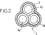
設置ダクト1は、図2に示すように、外装3内にまとめられた3本のチューブ1a,1b,1cから構成される。チューブ1a,1b,1cの各々は、単相円筒形電気ケーブル2を備える。単相ケーブルを組み合わせることによって、円筒形単相ケーブルを設置するために使用される技術および手段により地中に設置可能な高電力または中電力3相電気ケーブル2を製造することができる。
As shown in FIG. 2, the
したがって、設置装置に関して追加のコストがかからない。クローバ形の相の配置も維持される。さらに、単極(円筒形)ケーブル2を、約2.5kmの設置距離、すなわち、3極または撚りケーブル2により得られる設置距離よりもはるかに長い距離にわたって導入することができる。ケーブル2を導入するためのシステムは、前記ケーブル2が円形横断面を有するときに良好な密閉を提供する。加圧された搬送流体を使用するときに密閉が必要である。例えば熱成形された外装3は、このように形成されたアセンブリに機械的結合を提供するのに役立つ。
Therefore, there is no additional cost for the installation device. The clover-shaped phase arrangement is also maintained. Furthermore, the monopolar (cylindrical) cable 2 can be introduced over an installation distance of approximately 2.5 km, ie far longer than the installation distance obtained with a tripolar or twisted cable 2. The system for introducing the cable 2 provides a good seal when the cable 2 has a circular cross section. Sealing is necessary when using pressurized carrier fluid. For example, the
本発明によれば、3相電流を伝える撚り電気ケーブルを、円筒形電気ケーブル2の代わりに図1の設置ダクト1内に設置することもできる。
According to the present invention, a twisted electric cable that transmits a three-phase current can be installed in the
電気ケーブル2を設置ダクト1内に設置すると、前記設置ダクト1の機械的特性、すなわち穿刺強度、破砕強度、および引張強度によって、前記ケーブルを機械的攻撃から保護することができる。したがって、地中に直接埋設されるケーブルの場合のように、電気ケーブル2に保護特性を組み込む必要はない。本発明による方法を使用して設置された電気ケーブルは、直径がより小さくなり、より直径の小さいドラムに巻かれる。したがって、製造および輸送コストが同様の理由で低下する。
When the electric cable 2 is installed in the
図3は、電気ケーブルを設置ダクト内に設置する原理を示す図である。 FIG. 3 is a diagram showing the principle of installing an electric cable in an installation duct.
本発明による方法を実施するための装置は、電気ケーブル2を設置ダクト1内に押し込むための押込手段4を含む。押込手段は制御ユニット4aにより制御され、この制御ユニット4aは、ケーブルを前進させる速度および前記電気ケーブル2に加わる推力を制御するのに使用される。制御ユニット4aを使用して、ケーブル2を前進させる速度を、ドラム5からのケーブル2の巻戻しに対応する回転速度に同期させる。本発明による装置は、搬送流体(この場合は水6a)を含むタンク6をさらに有する。ポンプ7を使用して、10〜16バール(bar)で設置ダクト1に水を注入する。設置ダクト1内の水の流れは、電気ケーブル2の外装に加わる摩擦により、ある距離(設置距離と呼ばれる)にわたってケーブル2を設置ダクト1に沿って動かす。
The device for carrying out the method according to the invention comprises pushing means 4 for pushing the electrical cable 2 into the
13バールの水圧と、押込手段により加えられる約170デカニュートン(daN)の推力がある例を挙げると、例えば単位長さ当たりの重量が1.6kg/mの中電力ケーブルを、毎分20メートルの速度で1700メートルの距離にわたって設置することができる。 For example, with a water pressure of 13 bar and a thrust of about 170 decanontons (daN) applied by pushing means, for example, a medium power cable with a weight per unit length of 1.6 kg / m Can be installed over a distance of 1700 meters at speed.
水圧を調節するために、ポンプ7は更なる制御手段7aにより制御される。設置ダクト1内の水流速度および水圧は、ゲージ8,9によりそれぞれ測定される。
In order to adjust the water pressure, the pump 7 is controlled by a further control means 7a. The water flow velocity and the water pressure in the
図3および図4は、本発明による方法のステップを実施するための手段の例を概略的に示す。 3 and 4 schematically show examples of means for carrying out the steps of the method according to the invention.
図4に示すように設置ダクト1が装置10により敷設されると、図3に概略的に示す手段を使用して電気ケーブル2が前記設置ダクト1内に設置される。
When the
設置ダクト1を地中に敷設するための装置10は、好ましくは自走式であり、設置ダクト1を格納して巻くロール11を含む。
The
装置10が徐々に前進するときに溝14を掘るために、装置10はシリンダ13により装置10につながる車輪12を備える。
In order to dig the groove 14 as the
案内箱15を使用して設置ダクト1を溝14の底部に敷設する。好ましくは、溝14を埋め戻す前に、案内箱15に取り付けられた公知の装置により、設置ダクト1が警告膜または網16で覆われる。他の表示手段のうち、安価なのは、黒の3本のチューブを組み合わせるための外装を赤の外装に交換することであり、これにより、警告網を購入して敷設する必要がなくなる。
The
埋戻手段(図示せず)も装置10に取り付けられて、装置10と共に前進する。したがって、設置ダクト1は、一般的な技術で使用される全ての作用を使用して、装置10により地中の単一の経路内に敷設される。
A backfilling means (not shown) is also attached to the
装置10の通過後、装置10は、溝14から生じる材料を除去するための手段と、例えば設置ダクト1が配置されている溝14を埋め戻すために材料が後方へ移送される前に前記材料を粉砕することのできる処理手段とを特に有する。設置ダクト1が地中に敷設されると、電気ケーブル2を設置ダクト1内に設置することができる。電気ケーブル2が巻かれるドラム5は、この目的で使用される。
After the passage of the
図5は、例えば公知の手段により地中に敷設された設置ダクト1内に、電気ケーブル2を全体に設置した状態を概略的に示す。ポンプ7は、矢印Eで示すように、加圧水6aを設置ダクト1に注入する。搬送流体を構成する水6aは、所定の設置距離を進んだ後、矢印Sで示すように放出される。必要に応じて別のタンク6により供給される別のポンプ7を使用して、矢印Eで示すように、更なる水を設置ダクト1の別の区間に注入する。電気ケーブル2の最大可能設置距離を得るために、これをできる限り複数回繰り返す。
FIG. 5 schematically shows a state in which the electric cable 2 is installed as a whole in an
水6aは、約2.5kmの距離にわたって延びる各設置区間の間に配置された接近くぼみ11を介して設置ダクト1に注入される。
The water 6a is injected into the
本発明による方法を実施するための装置は、図7に概略的に示すように、チェーン20を有する押込手段4を含む。これらのチェーン20は、電気ケーブル2の両側に配置され、電気ケーブル2を設置ダクト1内に前進させるのに必要な推力を電気ケーブル2に加える。したがって、チェーン20が電気ケーブル2に加える推力は、設置ダクト1内の搬送流体の作用により補足される。ケーブル2の外装を保護する目的で、チェーン20の横方向圧力はできる限り均一にしなければならない。これは、2つ以上の同一の押込ユニットに推力を分配することにより達成される。この押込ユニットの数は、必要な全体の力に応じて変化する。
The apparatus for carrying out the method according to the invention comprises a pushing means 4 having a
例として、押込手段4は、直列に接続された3つの押込ユニット4a,4b,4cを含み、電気ケーブル2は、ドラム5から巻き戻されるとこれらのユニットを通過する。押込ユニット4a,4b,4cの各々はチェーン20と、電気ケーブル2に加わる前記チェーン20の締付力を調節するためのハンドル21とを備える。例えば3つの押込ユニット4a,4b,4cを直列に接続し、ハンドル21を使用して、チェーン20の所定の半径方向圧力を確実なものにするプレストレスを与えた締付力を加えることによって、製造により生じる、ケーブル2の外径の避けられない偏差を吸収することができる。したがって、設置性能に悪影響を与えるチェーンの滑りが防止される。
As an example, the pushing means 4 includes three pushing
図6に概略的に示すように、水取入部材22が設置ダクト1の入口に設けられ、ドラム5から巻き戻されるケーブルの長さを記録するためのメータ23も設けられる。
As schematically shown in FIG. 6, a
水等の搬送流体の取入部材22は、特に図10〜図12に示される。この部材は、固定ケーシング40と、固定ケーシング内で回転するように取り付けられた回転体41とを含む。
The
固定ケーシング40は、回転体41が回転するように収容される中空シリンダを共に画定する2つの半殻43,44から構成される。回転体41自体は、設置ダクト1が長手方向に通過する円筒体の形状を採用する。このダクトは、例えば、3本の枝管または相46〜48から構成される撚りアセンブリの形状の電気ケーブル45である。変形例として、このケーブルを、撚りアセンブリを形成する2つの相から構成することができる。
The fixed
搬送流体が入口オリフィス(図示せず)を介して固定ケーシング40に注入される。搬送流体が固定ケーシング40から漏出するのを防ぐために、回転体41は、ケーブル45の方向を横切って固定された、密閉仕切りを形成する密閉部材50を含む。
Carrier fluid is injected into the
この密閉部材50は環状であり、ケーブル45が通過する窓51を有する。この窓の形状は、撚りケーブルの外形に対して相補形である。ケーブルが3本の枝管から構成されるとき、窓は3つのローブ52〜54を有し、枝管46〜48の1本が各ローブを通過する。
The sealing
密閉部材50は2つの剛性フランジ55,56と、2つのフランジ間に挟まれるシール57とから形成される。フランジおよびシールは、ケーブルの方向を概ね横切る面に位置する。シール57は、撚りケーブルに密閉するように取り付けられ、動的シールの公知の材料であるゴム等から作られるのに対して、2つのフランジ55,56はアルミニウム合金から作られる。
The sealing
ケーブル45の周りに嵌合しやすくするために、各フランジは3つの部分60〜62,63〜65からそれぞれ構成される。シール57は、変形によりシール57をケーブル上に導入可能にするスリット66を備える。
To facilitate mating around the
回転体41は、(ケーブルの走行方向Fに対して)回転体の入口および出口にそれぞれ配置された2連の車輪67,68をさらに備える。各車輪は、ケーブルの撚りによって画定される螺旋の傾斜角度を維持するために、ケーブルの枝管46〜48の1本に接触して取り付けられる。
The rotating body 41 further includes two
密閉部材50は、ケーブル45が矢印Fの方向に沿って移動するときにケーブル45により回転させられる。この部材と一体の回転体41も回転し、簡単に密閉が得られるようになっている。
The sealing
チェーン20は、図8、図9に示すリンク25のアセンブリから構成される。各リンク25は、前記リンク25をつなぐように設計された鋼部26から構成される。ドリルホール26および/またはそれ自体公知の他の手段が、前記リンク25をつなぐために設けられる。各リンク25は、例えばアルミニウムから作られた、ボルト29により鋼部26上に嵌合する上部28を有する。上部28は、外側に、すなわち電気ケーブル2が確実に把持される側に、ほぼ横方向のリブ30を有する。例えば成形により得られるこれらのリブは、約1〜2mmの高さを有し、電気ケーブル2の外装を確実に把持する。チェーン20の循環方向にあるリブ30は、特別な形状、すなわちほぼ急な前面30a、ほぼ平坦な上面30b、および前面30aと比べて比較的緩やかな斜面を持つ後面30cとを有する。チェーン20の、したがってリブ30の循環方向は、図9に矢印Aで示される。これにより、ほぼ傾斜した前部30cが電気ケーブル2の外装に食い込む。
The
このような構成、および前記リブ30の大きさが比較的小さいことにより、電気ケーブル2の外装に与える有害な損傷が防止される。好ましくは、リブ30が上部28の横断面に半円筒形の外形を有し、その径が電気ケーブル2の外径に一致する。したがって、前記ケーブルはより大きな表面積にわたって最適に把持され、滑りの危険性は実質的に低下する。三角形または撚り形状の電気ケーブル2のアセンブリを設置ダクト1内に設置するためには、押込装置は、2本ではなく120゜で配置された3本の駆動ベルトを有し、各ベルトが平坦な、半円筒形ではない駆動歯を使用する。
Such a configuration and the relatively small size of the rib 30 prevent harmful damage to the exterior of the electric cable 2. Preferably, the rib 30 has a semi-cylindrical outer shape in the cross section of the
本発明により、高電力または中電力電気ケーブル2が設置ダクト1内に係合すると、前記電気ケーブル2は、単位長さ当たりの重量が比較的大きいため、設置ダクト1の最下部に位置して設置ダクト1を擦る傾向がある。したがって、水6a、すなわち搬送流体の循環のために使用できる自由容積は、電気ケーブル2の上のほうが下よりも大きくなる。その結果、電気ケーブル2の上下にそれぞれ位置する自由空間の間に速度差および圧力差が生じる。前記ケーブルの比重が1よりも大きくなるとすぐに、電気ケーブル2が設置ダクト1の下壁部を擦り、これは中電力および高電力電気ケーブルの場合に常に当てはまる。これにより、前記電気ケーブル2の外装と設置ダクト1とが擦れ、ケーブル2の外装に損傷を与える。ダクト1内で電気ケーブル2を囲む上部自由空間と下部自由空間との間に得られる圧力差により、前記電気ケーブル2が中央に位置させられ、水6aが前記ケーブル2の下方を少なくとも間欠的に流れることができるようになる。この比較的狭い下部自由空間の水の流れにより、摺擦接触している部分を冷却することができ、これにより摩擦係数が実質的に低下する。
According to the present invention, when the high power or medium power electric cable 2 is engaged in the
すなわち、摩擦接触領域で温度が20℃から40℃になるときに、摩擦係数が20%上昇することが確認されている。搬送流体としての水6aの流れにより、電気ケーブル2と設置ダクト1との接触部分の温度をある値より低く維持することができる。これにより、摩擦係数の上昇も避けられる。本発明による方法のコンテクスト(context)内で、搬送流体(この場合は水6a)を冷却するための手段を設け、必要に応じて、前記冷却手段を制御するために温度を制御するための手段を設けることが有益である。
That is, it has been confirmed that the friction coefficient increases by 20% when the temperature is changed from 20 ° C. to 40 ° C. in the friction contact region. The temperature of the contact portion between the electric cable 2 and the
測定点の温度および位置を測定するための特定の手段は、ネットワークにアクセスするためのチャンバがあるときに、特に敷設長さの端部に、または設置経路の途中にあるものと予測される。 A particular means for measuring the temperature and position of the measuring point is expected to be at the end of the installation length, or in the middle of the installation path, especially when there is a chamber for accessing the network.
本発明による方法は、温度測定により摩擦係数を制御することによって、比較的一定の設置速度(ケーブル2をダクト1内へ前進させる速度)を維持することができるという利点を有する。水6aの流れにより、電気ケーブル2の設置中にダクト1に発生する静電荷を除去することもできる。
The method according to the invention has the advantage that a relatively constant installation speed (speed at which the cable 2 is advanced into the duct 1) can be maintained by controlling the coefficient of friction by means of temperature measurements. The flow of the water 6a can also remove the static charge generated in the
1 設置ダクト
2 電気ケーブル
4 押込手段
4a,4b,4c 押込ユニット
5 ドラム
6a 水
14 溝
20 チェーン
22 取入部材
25 リンク
30 リブ
30a 前面
30b 上面
30c 後面
45 撚りケーブル
50 密閉部材
51 窓
52,53 ローブ
57 シール
1 Installation duct
2 Electric cable
4 Pushing means
4a, 4b, 4c Pushing unit
5 drums
6a water
14 groove
20 chain
22 Intake material
25 links
30 ribs
30a front
30b Top view
30c rear
45 twisted cable
50 Sealing member
51 windows
52,53 robes
57 Seal
Claims (15)
a)少なくとも1本の設置ダクト(1)が地中に敷設され、前記ケーブル(2)の外径と前記設置ダクトの内径との割合が1.2〜1.6となるように前記ダクトの前記内径が決定され、
b)前記ケーブルが前記ダクトに入る側で、外装に係合する少なくとも1つの押込部材により、前記ケーブル(2)が前記設置ダクト内に押し込まれ、
c)加圧水(6a)を含む流体が前記設置ダクト(1)に注入され、前記ケーブルが前方に押し込まれるときに前記ケーブルとのシールを提供し、前記流体に対する前記ケーブル(2)の比重が1よりも大きく、例えば1ないし3であり、前記水(6a)が中央配置流体として使用され、かつ前記ケーブル(2)と前記設置ダクト(1)との間の摩擦力により生じる熱エネルギーを除去するための流体として使用されるように、前記流体の注入が前記ケーブルの推力に関連して調節されることを特徴とする方法。Electrical cable having a conductive core wire (2a) and an insulation sheath (2b), including at least one single-phase element that maintains a voltage of at least 1000 volts and has a weight per unit length of at least 0.5 kg / m A method for installing (2),
a) The inner diameter of the duct is determined such that at least one installation duct (1) is laid in the ground, and the ratio of the outer diameter of the cable (2) to the inner diameter of the installation duct is 1.2 to 1.6. And
b) On the side where the cable enters the duct, the cable (2) is pushed into the installation duct by at least one pushing member that engages the exterior,
c) Fluid containing pressurized water (6a) is injected into the installation duct (1) and provides a seal with the cable when the cable is pushed forward; the specific gravity of the cable (2) with respect to the fluid is 1 greater than a 3 to for example, 1, removes heat energy generated by the frictional force between the water (6a) is used as the central arrangement a fluid medium is, and wherein the installation duct and cable (2) (1) The method is characterized in that the injection of the fluid is adjusted in relation to the thrust of the cable to be used as a fluid to do.
設置ダクト(1)を繰り出すための手段を持つ、溝(14)を掘るための手段と、
反対方向に回転し、かつ電気ケーブル(2)を把持して前記設置ダクト内に押し込む2本の重なったチェーン(20)を有する少なくとも1つの押込ユニット(4a,4b,4c)を含む、前記電気ケーブル(2)を前記設置ダクト(1)内に押し込むための手段(4)と、
前記流体の取入部材(22)と、前記ケーブルが前方に押し込まれるときに前記ケーブル(2)について密閉するための密閉部材(50)とを含む、流体を前記設置ダクト(1)に注入するための手段と、を含むことを特徴とする装置。An apparatus for carrying out the method according to any one of claims 1 to 6,
Means for digging the groove (14) with means for paying out the installation duct (1);
Including at least one pushing unit (4a, 4b, 4c) having two overlapping chains (20) that rotate in opposite directions and grip the electric cable (2) and push it into the installation duct. Means (4) for pushing the cable (2) into the installation duct (1);
Fluid is injected into the installation duct (1), including the fluid intake member (22) and a sealing member (50) for sealing the cable (2) when the cable is pushed forward Means for providing a device.
Applications Claiming Priority (2)
| Application Number | Priority Date | Filing Date | Title |
|---|---|---|---|
| FR0116327A FR2833770A1 (en) | 2001-12-17 | 2001-12-17 | Method of installing high tension underground electric cables, uses high pressure water under pressure as a carrier and cooling medium |
| PCT/FR2002/004373 WO2003052894A1 (en) | 2001-12-17 | 2002-12-16 | Method for installing a high or medium power cable in the ground |
Publications (2)
| Publication Number | Publication Date |
|---|---|
| JP2005523673A JP2005523673A (en) | 2005-08-04 |
| JP4204475B2 true JP4204475B2 (en) | 2009-01-07 |
Family
ID=8870593
Family Applications (1)
| Application Number | Title | Priority Date | Filing Date |
|---|---|---|---|
| JP2003553682A Expired - Lifetime JP4204475B2 (en) | 2001-12-17 | 2002-12-16 | Methods for installing high or medium power cables in the ground |
Country Status (12)
| Country | Link |
|---|---|
| US (1) | US7156584B2 (en) |
| EP (1) | EP1456923B1 (en) |
| JP (1) | JP4204475B2 (en) |
| CN (1) | CN100435437C (en) |
| AT (1) | ATE306731T1 (en) |
| AU (1) | AU2002364994A1 (en) |
| CA (1) | CA2474081C (en) |
| DE (1) | DE60206657T2 (en) |
| DK (1) | DK1456923T3 (en) |
| ES (1) | ES2249641T3 (en) |
| FR (1) | FR2833770A1 (en) |
| WO (1) | WO2003052894A1 (en) |
Families Citing this family (10)
| Publication number | Priority date | Publication date | Assignee | Title |
|---|---|---|---|---|
| US20060291960A1 (en) * | 2005-06-24 | 2006-12-28 | Todd Robert R | Aqua gopher |
| JP5666612B2 (en) | 2009-11-05 | 2015-02-12 | プリュメタ、ホールディング、ソシエテ、アノニムPlumettaz Holding S.A. | Method, pig and pressure housing for laying elongated elements |
| GB2522230A (en) * | 2014-01-17 | 2015-07-22 | Deflux Holdings Ltd | Method and apparatus for removing a cable core from a cable sheath |
| CN103851257B (en) * | 2014-03-18 | 2015-10-28 | 国家电网公司 | Based on the trustship construction process in laying cable duct bank |
| US9711956B1 (en) * | 2014-05-21 | 2017-07-18 | Lee D. Welch | Hinged cable guide |
| US20200295545A1 (en) | 2019-03-15 | 2020-09-17 | Novinium, Inc. | Fluid injection system with smart injection and receiver tanks |
| EP3761467A1 (en) * | 2019-07-03 | 2021-01-06 | Siemens Gamesa Renewable Energy A/S | Method of installing a transmission cable arrangement |
| CN111864641A (en) * | 2020-08-26 | 2020-10-30 | 国家电网有限公司 | Cable laying device for electric power and convenient for laying cable into pipeline |
| CN112938612A (en) * | 2021-01-27 | 2021-06-11 | 包仁钦 | Labor-saving underground wiring device |
| US11214450B1 (en) * | 2021-03-11 | 2022-01-04 | Cciip Llc | Method of proofing an innerduct/microduct and proofing manifold |
Family Cites Families (19)
| Publication number | Priority date | Publication date | Assignee | Title |
|---|---|---|---|---|
| GB1228372A (en) * | 1967-05-03 | 1971-04-15 | ||
| US4048807A (en) * | 1975-01-29 | 1977-09-20 | Bechtel International Corporation | Methods for emplacing and maintaining transmission lines |
| US4185809A (en) * | 1978-01-27 | 1980-01-29 | Nelson Jonnes | Method and apparatus for pulling lightweight cable |
| US4232981A (en) * | 1978-06-26 | 1980-11-11 | Bechtel International Corporation | Beaded liquid product and method for reducing coefficient of friction |
| US4437789A (en) * | 1981-09-24 | 1984-03-20 | Gk Technologies, Incorporated | Method and means for protecting buried cable from rodent damage |
| US4629363A (en) * | 1984-11-02 | 1986-12-16 | Rose Timothy M | Continuous conduit laying apparatus |
| US4911774A (en) * | 1985-07-24 | 1990-03-27 | Tape Automation, Ltd. | Splicing and loading of tape into cassettes with a stationary splicing block |
| GB2190457B (en) * | 1986-05-17 | 1990-12-19 | Stc Plc | Hydraulic cable installation system |
| DE3780400D1 (en) * | 1986-10-15 | 1992-08-20 | Rudolf Harmstorf | METHOD AND DEVICE FOR INSERTING A ROPE-LIKE ELEMENT IN A CABLE TUBE PIPE. |
| BE1003914A3 (en) * | 1989-06-22 | 1992-07-14 | Corstjens Helena Michel | Method for increasing the passage of a pipe in the ground and thus used hose. |
| DE4115907A1 (en) * | 1990-07-26 | 1992-11-19 | Siemens Ag | Cable plough for laying cables underground - has cutting wheel lowerable to cut ground before plough blade acts |
| GB9118848D0 (en) * | 1991-09-03 | 1991-10-16 | Davison Geoffrey W | Soil implement |
| SE501770C2 (en) * | 1992-10-20 | 1995-05-08 | Meab Mobile Equipment Ab | Arrangement for inserting one or more cables into a pipe intended for the cable's enclosure using a fluid |
| FR2720873B1 (en) * | 1994-06-06 | 1996-08-23 | Alain Pecot | Method and device for laying an underground telecommunications cable. |
| US5813658A (en) * | 1994-11-23 | 1998-09-29 | Arnco Corporation | Cable feeding apparatus |
| US5897103A (en) * | 1995-07-24 | 1999-04-27 | Koninklijke Ptt Nederland N.V. | Method for installing cables |
| FR2774521B1 (en) * | 1998-02-04 | 2000-03-31 | France Telecom | METHOD FOR INSTALLING AND / OR REMOVING A CABLE IN CABLE CROSSING DUCTS AND DEVICE FOR IMPLEMENTING IT |
| FR2807226B1 (en) * | 2000-03-31 | 2002-08-09 | Marais Sa | METHOD AND DEVICE FOR PROPELLING A CABLE OR THE LIKE INSIDE A SHEATH |
| US6848541B2 (en) * | 2002-07-11 | 2005-02-01 | Nkf Kabel B.V. | Optical cable installation with cable lubricator |
-
2001
- 2001-12-17 FR FR0116327A patent/FR2833770A1/en not_active Withdrawn
-
2002
- 2002-12-16 CN CNB02824723XA patent/CN100435437C/en not_active Expired - Lifetime
- 2002-12-16 ES ES02804928T patent/ES2249641T3/en not_active Expired - Lifetime
- 2002-12-16 AU AU2002364994A patent/AU2002364994A1/en not_active Abandoned
- 2002-12-16 DE DE60206657T patent/DE60206657T2/en not_active Expired - Lifetime
- 2002-12-16 JP JP2003553682A patent/JP4204475B2/en not_active Expired - Lifetime
- 2002-12-16 US US10/499,328 patent/US7156584B2/en not_active Expired - Lifetime
- 2002-12-16 WO PCT/FR2002/004373 patent/WO2003052894A1/en active IP Right Grant
- 2002-12-16 AT AT02804928T patent/ATE306731T1/en active
- 2002-12-16 CA CA2474081A patent/CA2474081C/en not_active Expired - Lifetime
- 2002-12-16 EP EP02804928A patent/EP1456923B1/en not_active Expired - Lifetime
- 2002-12-16 DK DK02804928T patent/DK1456923T3/en active
Also Published As
| Publication number | Publication date |
|---|---|
| US20050036843A1 (en) | 2005-02-17 |
| ATE306731T1 (en) | 2005-10-15 |
| FR2833770A1 (en) | 2003-06-20 |
| DE60206657D1 (en) | 2005-11-17 |
| US7156584B2 (en) | 2007-01-02 |
| WO2003052894A1 (en) | 2003-06-26 |
| DK1456923T3 (en) | 2005-12-27 |
| AU2002364994A1 (en) | 2003-06-30 |
| ES2249641T3 (en) | 2006-04-01 |
| CA2474081C (en) | 2013-02-05 |
| EP1456923A1 (en) | 2004-09-15 |
| EP1456923B1 (en) | 2005-10-12 |
| JP2005523673A (en) | 2005-08-04 |
| DE60206657T2 (en) | 2006-06-22 |
| CN100435437C (en) | 2008-11-19 |
| CA2474081A1 (en) | 2003-06-26 |
| CN1669196A (en) | 2005-09-14 |
Similar Documents
| Publication | Publication Date | Title |
|---|---|---|
| JP4204475B2 (en) | Methods for installing high or medium power cables in the ground | |
| US6572081B2 (en) | Installation of guide tubes in a protective duct | |
| JPH0222921B2 (en) | ||
| GB2260180A (en) | Repairing undergroud pipe | |
| US10533683B2 (en) | Removable cover intended for being arranged opposite a fluid-transport pipe submerged in a body of water, associated intervention assembly and method | |
| US6134766A (en) | Method and apparatus for installing cable-like elements inside pipes | |
| CN110573779B (en) | Method for laying a pipe bundle on the seabed | |
| KR101137778B1 (en) | Execution method using installer of manhole pipe | |
| US7018136B2 (en) | Method installing a duct, device for carrying out said method, and a tape-shape element for use with said method | |
| KR20000006990A (en) | Method and apparatus for inverting impregnated tube in pipe | |
| US6200397B1 (en) | Method and apparatus for strip anode wrapping for cathodic protection of tubular members | |
| CN113958781A (en) | Method for mounting a gas transport device | |
| US11846378B2 (en) | Heated pipeline with high heating efficiency | |
| JP2943858B2 (en) | How to insert a hose with nozzle in a pipe | |
| JPH07107430B2 (en) | How to insert a small diameter tube | |
| JP2688756B2 (en) | Underground pipeline repair device and repair method | |
| OA20562A (en) | A heated pipeline with high heating efficiency. | |
| JP2000166043A (en) | Device for filling inside of conduit line with sand and method for filling with sand | |
| JPH01255413A (en) | Repair work for underground conduit line | |
| JPH03183309A (en) | Installation of cable in underground piping | |
| JPH03182019A (en) | Cable laying apparatus for buried pipe | |
| JPH03183310A (en) | Device for laying cable in underground piping | |
| JPH0851713A (en) | Method for pushing cable into conduit | |
| JPH0491609A (en) | Cable laying method in buried pipe |
Legal Events
| Date | Code | Title | Description |
|---|---|---|---|
| A529 | Written submission of copy of amendment under article 34 pct |
Free format text: JAPANESE INTERMEDIATE CODE: A529 Effective date: 20040616 |
|
| A621 | Written request for application examination |
Free format text: JAPANESE INTERMEDIATE CODE: A621 Effective date: 20050513 |
|
| A711 | Notification of change in applicant |
Free format text: JAPANESE INTERMEDIATE CODE: A712 Effective date: 20060703 |
|
| A521 | Request for written amendment filed |
Free format text: JAPANESE INTERMEDIATE CODE: A821 Effective date: 20060703 |
|
| A131 | Notification of reasons for refusal |
Free format text: JAPANESE INTERMEDIATE CODE: A131 Effective date: 20071009 |
|
| A521 | Request for written amendment filed |
Free format text: JAPANESE INTERMEDIATE CODE: A523 Effective date: 20071221 |
|
| A521 | Request for written amendment filed |
Free format text: JAPANESE INTERMEDIATE CODE: A523 Effective date: 20071221 |
|
| A02 | Decision of refusal |
Free format text: JAPANESE INTERMEDIATE CODE: A02 Effective date: 20080401 |
|
| A521 | Request for written amendment filed |
Free format text: JAPANESE INTERMEDIATE CODE: A523 Effective date: 20080610 |
|
| A521 | Request for written amendment filed |
Free format text: JAPANESE INTERMEDIATE CODE: A523 Effective date: 20080814 |
|
| A911 | Transfer to examiner for re-examination before appeal (zenchi) |
Free format text: JAPANESE INTERMEDIATE CODE: A911 Effective date: 20080825 |
|
| TRDD | Decision of grant or rejection written | ||
| A01 | Written decision to grant a patent or to grant a registration (utility model) |
Free format text: JAPANESE INTERMEDIATE CODE: A01 Effective date: 20080916 |
|
| A01 | Written decision to grant a patent or to grant a registration (utility model) |
Free format text: JAPANESE INTERMEDIATE CODE: A01 |
|
| A61 | First payment of annual fees (during grant procedure) |
Free format text: JAPANESE INTERMEDIATE CODE: A61 Effective date: 20081014 |
|
| FPAY | Renewal fee payment (event date is renewal date of database) |
Free format text: PAYMENT UNTIL: 20111024 Year of fee payment: 3 |
|
| R150 | Certificate of patent or registration of utility model |
Ref document number: 4204475 Country of ref document: JP Free format text: JAPANESE INTERMEDIATE CODE: R150 Free format text: JAPANESE INTERMEDIATE CODE: R150 |
|
| FPAY | Renewal fee payment (event date is renewal date of database) |
Free format text: PAYMENT UNTIL: 20111024 Year of fee payment: 3 |
|
| FPAY | Renewal fee payment (event date is renewal date of database) |
Free format text: PAYMENT UNTIL: 20121024 Year of fee payment: 4 |
|
| R250 | Receipt of annual fees |
Free format text: JAPANESE INTERMEDIATE CODE: R250 |
|
| FPAY | Renewal fee payment (event date is renewal date of database) |
Free format text: PAYMENT UNTIL: 20131024 Year of fee payment: 5 |
|
| R250 | Receipt of annual fees |
Free format text: JAPANESE INTERMEDIATE CODE: R250 |
|
| R250 | Receipt of annual fees |
Free format text: JAPANESE INTERMEDIATE CODE: R250 |
|
| R250 | Receipt of annual fees |
Free format text: JAPANESE INTERMEDIATE CODE: R250 |
|
| R250 | Receipt of annual fees |
Free format text: JAPANESE INTERMEDIATE CODE: R250 |
|
| R250 | Receipt of annual fees |
Free format text: JAPANESE INTERMEDIATE CODE: R250 |
|
| R250 | Receipt of annual fees |
Free format text: JAPANESE INTERMEDIATE CODE: R250 |
|
| R250 | Receipt of annual fees |
Free format text: JAPANESE INTERMEDIATE CODE: R250 |
|
| R250 | Receipt of annual fees |
Free format text: JAPANESE INTERMEDIATE CODE: R250 |
|
| R250 | Receipt of annual fees |
Free format text: JAPANESE INTERMEDIATE CODE: R250 |
|
| R250 | Receipt of annual fees |
Free format text: JAPANESE INTERMEDIATE CODE: R250 |
|
| R250 | Receipt of annual fees |
Free format text: JAPANESE INTERMEDIATE CODE: R250 |
|
| EXPY | Cancellation because of completion of term |