JP4201698B2 - Tracking error signal detector - Google Patents
Tracking error signal detector Download PDFInfo
- Publication number
- JP4201698B2 JP4201698B2 JP2003423113A JP2003423113A JP4201698B2 JP 4201698 B2 JP4201698 B2 JP 4201698B2 JP 2003423113 A JP2003423113 A JP 2003423113A JP 2003423113 A JP2003423113 A JP 2003423113A JP 4201698 B2 JP4201698 B2 JP 4201698B2
- Authority
- JP
- Japan
- Prior art keywords
- signal
- light receiving
- phase
- output
- circuit
- Prior art date
- Legal status (The legal status is an assumption and is not a legal conclusion. Google has not performed a legal analysis and makes no representation as to the accuracy of the status listed.)
- Expired - Fee Related
Links
Images


Description
この発明は、本発明は、分割受光素子の出力信号間の位相差からトラッキング誤差信号を検出するトラッキング方式(以下、DPD法(Differential Phase Detection)という。)に関し、特に、記録密度が高く、符号間干渉の大きいシステムにおいて、当該トラッキング誤差信号の品質が劣化することを改良したトラッキング誤差信号検出装置に関する。 The present invention relates to a tracking method for detecting a tracking error signal from a phase difference between output signals of divided light receiving elements (hereinafter referred to as a DPD method (Differential Phase Detection)). The present invention relates to a tracking error signal detection apparatus improved in that the quality of the tracking error signal is deteriorated in a system having a large inter-interference.
近年、分割受光素子の出力信号間の位相差からトラッキング誤差信号を検出するトラッキング方式(DPD法(Differential Phase Detection))が注目され、光ディスクドライブ装置に多く用いられている。 In recent years, a tracking method (DPD method (Differential Phase Detection)) that detects a tracking error signal from a phase difference between output signals of a divided light receiving element has attracted attention and is often used in an optical disk drive device.
図6は、従来のトラッキング誤差信号検出装置のブロック図を示すものである。 FIG. 6 shows a block diagram of a conventional tracking error signal detection apparatus.
図6において、601は分割受光素子であり、互いに直交する分割線で分割された受光素子601a、601b、601c、601dで構成される。
In FIG. 6,
602a、602bは加算器であり、それぞれ対角に位置する受光素子601aと受光素子601cの出力及び受光素子601bと受光素子601dの出力を加算し、信号AC1と信号BD1を出力する。即ち、加算器602aにて、受光素子601aと受光素子601cの出力を加算し、信号AC1を出力し、加算器602bにて、受光素子601bと受光素子601dの出力を加算し、信号BD1を出力する。
この受光素子601は、光ディスクにおける情報トラック付近に読み取りレーザービームを照射した際に生じる反射ビームの光路中に置かれている。上記光ディスクは所定の速度で回転しており、その反射光は上記情報トラックに記された情報ピットで変調され、それが各受光素子601a、601b、601c、601dから電気信号として出力される。
The
603a、603bはイコライザであり、信号AC1及び信号BD1の直流成分を除去するとともに、信号成分の周波数帯域のブーストを行う。イコライザ603aには、信号AC1が与えられ、イコライズした信号AC2を出力する。イコライザ603bには信号BD1が与えられ、イコライズした信号BD2を出力する。
604a、604bは二値化回路であり、上記イコライザを通過した信号AC1及びBD1をそれぞれグランドレベルを閾値にして二値化を行い、2値信号のAC3及びBD3を出力する。
605は位相比較器(PD)であり、出力パルス信号間の位相差を検出して位相検出パルスを出力をする。位相比較器605は二値化回路604a、604bが出力する信号AC3とBD3を入力する端子P1とP2を備え、P1端子には二値化回路604aからの信号AC3が、P2端子には二値化回路604bからの信号BD3が入力される。信号AC3の位相が信号BD3に対して進んでいる場合には、出力端子Uより位相検出パルスAC+が出力され、信号BD3の位相が信号AC3に対して進んでいる場合には、出力端子Dより位相検出パルスBD+が出力される。
606a、606bはローパスフィルタ(LPF)であり、上記位相検出パルスを積分するとともにノイズ成分を除去する。607は差動増幅器であり、上記LPF606a、606bの出力を差動増幅することにより、トラッキング誤差信号(TE)を得る。
以上のように構成されたトラッキング誤差検出装置について、その動作を以下に説明する。 The operation of the tracking error detection apparatus configured as described above will be described below.
まず、レーザービームが情報トラックの中心線を走査する場合、分割受光素子601に投射される反射光は情報ピットによる干渉作用で強度分布が発生し、しかもその分布はトラック接線方向に対称に変化する。その結果、上記合成信号AC1、BD1は同相で変化する。一方、レーザービームがトラック中心線より外れると上記強度分布は反射光軸を中心に回転するように変化する。尚、回転方向はトラックずれの方向に依存する。この変化は、合成出力AC1、BD1の相互位相差として検出される。従って、両合成出力の位相差を位相比較器605で検出し、位相差をパルス信号として出力した後、ローパスフィルタ606a、606bでノイズ成分を除去すれば、レーザービームとトラック中心線の相互の位置誤差に応じた信号、すなわち、トラッキング誤差信号を得ることができる。
First, when the laser beam scans the center line of the information track, the reflected light projected on the divided
図7は、従来のトラッキング誤差信号検出装置にてDVD(Digital Versatile Disc)のトラッキング誤差信号を得る際のタイミングチャートである。ピット列は、4Tのピット、3Tのスペース、3Tピット、5Tスペース、5Tピット、3Tスペース、5Tピットのように並んでいる。ここで、Tとはチャネルクロック周波数の逆数で示される時間であり、基準速度で再生した場合のピット長をn×Tの形式で示している。DVDの場合、チャネルクロックは26.16MHzであり、1Tに相当する時間は約38.2nsecであり、また、ピット長は3T〜11T及び14Tで構成されている。 FIG. 7 is a timing chart when a tracking error signal of a DVD (Digital Versatile Disc) is obtained by a conventional tracking error signal detection device. The pit rows are arranged like 4T pits, 3T spaces, 3T pits, 5T spaces, 5T pits, 3T spaces, and 5T pits. Here, T is the time indicated by the reciprocal of the channel clock frequency, and indicates the pit length in the form of n × T when reproduced at the reference speed. In the case of DVD, the channel clock is 26.16 MHz, the time corresponding to 1T is about 38.2 nsec, and the pit length is composed of 3T to 11T and 14T.
本図では、レーザービームがピット列の中心から若干ずれている場合を示しており、図中(a)は信号AC2であり(実線にて示す)、(b)は信号BD2であり(破線にて示す)、信号AC2が信号BD2に対して位相が進んでいる。(c)は信号AC2を二値化回路604aにてグランドレベルを閾値として二値化した信号AC3である。同様に、(d)は信号BD2を二値化回路604bにてグランドレベルを閾値にて二値化した信号BD3である。これらの信号AC3、BD3が位相比較器605に入力され、この場合、信号AC3が信号BD3に対して位相が進んでいるため、位相比較器605の出力端子Uより位相検出パルスAC+(図中の(e))が出力される。
This figure shows a case where the laser beam is slightly deviated from the center of the pit row, in which (a) is the signal AC2 (shown by a solid line), and (b) is the signal BD2 (shown by a broken line). The phase of the signal AC2 is advanced with respect to the signal BD2. (C) is a signal AC3 obtained by binarizing the signal AC2 with the ground level as a threshold by the
この位相検出パルスはレーザービームがディスク上のピットに突入する際と脱出する際に出力される。尚、本例は信号AC3の位相が進んでいる場合であるため、位相比較器605のもう一方の出力端子Dからの位相検出パルスBD+(図中の(f))は出力されない。
This phase detection pulse is output when the laser beam enters and exits a pit on the disk. In this example, since the phase of the signal AC3 is advanced, the phase detection pulse BD + ((f) in the figure) from the other output terminal D of the
このようにして得られた位相検出パルスをLPF606a、及び606bと差動増幅器607により、トラッキング誤差信号を生成する。
A tracking error signal is generated by the
レーザービームのピット列中心からのずれ方向が逆の場合は、位相比較器605の出力端子Uからは位相検出パルスAC+が出力されず、もう一方の出力端子Dからの位相検出パルスBD+が出力されることになる。
When the direction of deviation of the laser beam from the center of the pit row is opposite, the phase detection pulse AC + is not output from the output terminal U of the
高密度記録された光ディスク媒体におけるトラッキング誤差信号の精度を上げるために、DPD法を改良した例が種々提案されている。例えば、DPD回路の二値化回路部前に最短ピット列の信号振幅を上げるために高域強調フィルタを搭載したもの(特許文献1参照)、ディスク上の傷等により、DPD回路の位相比較用パルスが異常に長くなった場合、パルス幅を制限し、且つ、逆相のパルスを発生させ、ノイズ成分をキャンセルするもの(特許文献2参照)、DPD回路の二値化回路部前にイコライザを備え、高域強調とノイズ除去を行うもの(特許文献3参照)などがある。
しかしながら、上記のような構成では、トラック上に記録されている情報の密度が高くなるほどトラッキング誤差信号の検出雑音が増えるという問題点を有していた。特に、最短ピット列の振幅低下は著しい。さらに、最短ピット列の近くに長いピットが存在すると、強い符号間干渉によって最短ピットが長いピットに吸収され独立には認識しにくくなる。これを従来のDPD法の二値化回路に与えると、最短ピット部にて閾値を越える場合と越えない場合が生じ、これにより位相比較を行うパルス信号が欠落し、トラッキング誤差信号を誤検出することになり、その結果、トラッキング誤差信号に大きなノイズが生じることになる。 However, the above configuration has a problem that the detection error of the tracking error signal increases as the density of information recorded on the track increases. In particular, the amplitude drop of the shortest pit row is remarkable. Furthermore, if there is a long pit near the shortest pit row, the shortest pit is absorbed by the long pit due to strong intersymbol interference and is difficult to recognize independently. When this is applied to a conventional DPD method binarization circuit, there are cases where the threshold value is exceeded or not exceeded at the shortest pit portion, thereby missing a pulse signal for phase comparison and erroneously detecting a tracking error signal. As a result, large noise is generated in the tracking error signal.
図8、図9は、図6で示した従来のDPD回路を用いて高密度光ディスクメディア(例えば、青紫LDを用いるHD DVD)での回路動作を示している。HD DVDでは、チャネルクロックが64.8MHzとDVDに比べ2.5倍ほど高速であり、さらに最短ピット長として2Tが存在する。よって、DVDと比較して最短ピットでの信号AC1、BD1の振幅は非常に小さく、また、符号間干渉の影響も大きくなる。例えば、図中の6Tスペースと5Tスペースの間にある2Tマークや、6Tマークと5Tマークの間にある2Tスペースの振幅は非常に小さくなり、二値化回路604a、604bの閾値電圧であるグランドレベルを越えず、意図する二値化出力が得られない場合が生じる。
FIGS. 8 and 9 show circuit operations on a high-density optical disc medium (for example, HD DVD using blue-violet LD) using the conventional DPD circuit shown in FIG. In HD DVD, the channel clock is 64.8 MHz, which is about 2.5 times faster than DVD, and 2T exists as the shortest pit length. Therefore, the amplitude of the signals AC1 and BD1 at the shortest pit is very small as compared with DVD, and the influence of intersymbol interference is also large. For example, the amplitude of the 2T mark between the 6T space and the 5T space in the figure, and the 2T space between the 6T mark and the 5T mark are very small, and the ground voltage that is the threshold voltage of the
図8、図9においても、レーザービームがピット列の中心から若干ずれている場合を示している。図8では、信号BD2を二値化回路604bにて二値化した信号BD3(図中の(d))において、意図した二値化が出来なかった例を示している。本来は、点線で示す二値化信号を得たいが、図8に示すように、実線で示す二値化信号が出力される。その結果、位相差検出パルスAC+に意図しない長い幅のパルスが出力されている。
8 and 9 also show a case where the laser beam is slightly deviated from the center of the pit row. FIG. 8 shows an example in which the intended binarization cannot be performed in the signal BD3 ((d) in the figure) obtained by binarizing the signal BD2 by the
図9は、信号AC2を二値化回路604aにて二値化した信号AC3(図中の(c))において、意図した二値化が出来なかった例を示しており、この場合も、本来は、点線で示す二値化信号を得たいが、実線で示す二値化信号が出力される。その結果、位相差検出パルスAC+は意図する箇所で生成されず、逆に、位相差検出パルスBD+に意図しないパルスが出力されてしまう。
FIG. 9 shows an example in which the intended binarization cannot be performed in the signal AC3 ((c) in the figure) obtained by binarizing the signal AC2 by the
このように、高密度光ディスクメディアでは最短ピット長の振幅が小さくなり、また、符号間干渉が大きいため、従来のDPD回路では誤検出が生じやすく、その結果、ノイズ成分を含んだトラッキング誤差信号となってしまう。 As described above, since the amplitude of the shortest pit length is small in high-density optical disc media and the intersymbol interference is large, erroneous detection is likely to occur in the conventional DPD circuit. As a result, a tracking error signal including a noise component and turn into.
本発明は上記問題点に鑑みなされたものにして、高密度記録された光ディスク媒体を用いても十分なS/Nでトラッキング誤差信号が検出できるトラッキング誤差検出装置を提供するものである。 The present invention has been made in view of the above problems, and provides a tracking error detection device capable of detecting a tracking error signal with sufficient S / N even when an optical disk medium recorded with high density is used.
前述したような問題点を解決するために、本発明のトラッキング誤差信号検出装置は、光学的情報記録媒体の情報トラック付近にレーザービームを照射する手段と、その反射ビームの光路中に設けられた分割受光手段と、前記分割受光手段を構成する第1の受光素子群と第2の受光素子群の出力信号相互の位相差を検出してトラッキング誤差信号を得るトラッキング誤差信号検出装置であって、前記第1と第2の受光素子群の出力信号の各々を、第1の閾値電圧レベルにて二値化する第1の二値化回路と、前記第1の閾値より低い電圧レベルの第2の閾値電圧レベルにて二値化する第2の二値化回路と、第1の閾値電圧レベルにて二値化された第1と第2の受光素子群の出力信号の位相差を検出する第1の位相差検出器と、第2の閾値電圧レベルにて二値化された第1と第2の受光素子群の出力信号の位相差を検出する第2の位相差検出器とを備え、第1及び第2の位相差検出器が各々出力する進み位相検出パルスと遅れ位相検出パルスの内、どちらの進み位相差検出パルス或いはどちらの遅れ位相差検出パルスを利用するかを、前記第1の二値化回路で二値化した信号の立ち下がりと前記第2の二値化回路で二値化した信号の立ち上がりのタイミングに対応して生成される選択信号にて選択する選択回路を備えたことを特徴とする。 In order to solve the problems as described above, the tracking error signal detection device of the present invention is provided in the optical path of the reflected beam and means for irradiating the laser beam near the information track of the optical information recording medium. A divided light receiving means, and a tracking error signal detecting device for obtaining a tracking error signal by detecting a phase difference between output signals of a first light receiving element group and a second light receiving element group constituting the divided light receiving means, A first binarization circuit that binarizes each of the output signals of the first and second light receiving element groups at a first threshold voltage level; and a second that has a voltage level lower than the first threshold . Detecting a phase difference between output signals of the second binarization circuit binarized at the first threshold voltage level and the first and second light receiving element groups binarized at the first threshold voltage level. A first phase difference detector and a second threshold voltage level; And a second phase difference detector for detecting a phase difference between the output signals of the first and second light receiving element groups binarized by the first and second phase difference detectors, respectively. Of the advanced phase detection pulse and delayed phase detection pulse to be detected, which of the advanced phase difference detection pulse or which delayed phase difference detection pulse is to be used is determined by the rise of the signal binarized by the first binarization circuit. A selection circuit is provided that makes a selection based on a selection signal generated corresponding to the timing of the falling and the rising of the signal binarized by the second binarization circuit .
また、本発明は、第1の閾値電圧レベルはグランドレベルよりも高い電圧値に設定され、第2の閾値電圧レベルはグランドレベルよりも低い電圧値に設定することができる。 In the present invention, the first threshold voltage level can be set to a voltage value higher than the ground level, and the second threshold voltage level can be set to a voltage value lower than the ground level.
更に、前記選択回路は、第1の受光素子群の出力信号を第1及び第2の閾値電圧レベルにて二値化した信号の立ち上がり、及び、立ち下りタイミングより選択信号を生成する位相差検出パルス選択回路と、第2の受光素子群の出力信号を第1、及び、第2の閾値電圧レベルにて二値化した信号の立ち上がり、及び、立ち下りタイミングより選択信号を生成する位相差検出パルス選択回路と、を備えて構成することができる。 Further, the selection circuit generates a selection signal based on the rising and falling timings of a signal obtained by binarizing the output signal of the first light receiving element group at the first and second threshold voltage levels. Phase difference detection that generates a selection signal from the rise and fall timings of a signal obtained by binarizing the output signal of the pulse selection circuit and the second light receiving element group at the first and second threshold voltage levels And a pulse selection circuit.
上記のように本発明は、二値化回路に二種類の閾値電圧を設定することにより、高密度光ディスクの最短ピット列で生じる信号振幅の低さ、符号間干渉等によるトラッキングエラー誤差信号のノイズを低減することができる。 As described above, according to the present invention, by setting two kinds of threshold voltages in the binarization circuit, the noise of the tracking error error signal due to the low signal amplitude, the intersymbol interference, etc. generated in the shortest pit row of the high-density optical disc. Can be reduced.
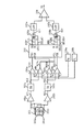
以下、この発明の実施形態を図面に基づいて説明する。図1は、本発明の一実施形態に従うトラッキング誤差信号検出装置を示すブロック図である。 Embodiments of the present invention will be described below with reference to the drawings. FIG. 1 is a block diagram illustrating a tracking error signal detection apparatus according to an embodiment of the present invention.
図1において、101は分割受光素子であり、互いに直交する分割線で分割された受光素子101a、101b、101c、101dで構成される。
In FIG. 1,
102a、102bは加算器であり、それぞれ対角に位置する受光素子101aと受光素子101cの出力及び受光素子101bと受光素子101dの出力を加算し、信号AC1と信号BD1を出力する。即ち、加算器102aにて、受光素子101aと受光素子101cの出力を加算し、信号AC1を出力し、加算器102bにて、受光素子101bと受光素子101dの出力を加算し、信号BD1を出力する。
この受光素子101は、光ディスクにおける情報トラック付近に読み取りレーザービームを照射した際に生じる反射ビームの光路中に置かれている。上記光ディスクは所定の速度で回転しており、その反射光は上記情報トラックに記された情報ピットで変調され、それが各受光素子101a、101b、101c、101dから電気信号として出力される。
The
103a、103bはイコライザ(EQ)であり、信号AC1及び信号BD1の直流成分を除去するとともに、信号成分の周波数帯域のブーストを行う。イコライザ613aには、信号AC1が与えられ、イコライズした信号AC2を出力する。イコライザ103bには信号BD1が与えられ、イコライズした信号BD2を出力する。
104a、104b、104c、104dは二値化回路であり、120a、120bは基準電圧発生回路である。二値化回路104aと二値化回路104bの+入力端子には、イコライザ103aの出力である信号AC2がそれぞれ入力される。二値化回路104cと二値化回路104dの+入力端子には、イコライザ103bの出力である信号BD2がそれぞれ入力される。
また、基準電圧発生回路120aは、グランドレベルより若干電圧の高いVHを出力す
る回路であり、その出力は、第1の二値化回路としての二値化回路104aと二値化回路104cの−入力端子にそれぞれ接続されている。また、基準電圧発生回路120bは、グランドレベルより若干電圧の低いVLを出力する回路であり、その出力は、第2の二値化回路としての二値化回路104bと二値化回路104dの−入力端子にそれぞれ接続されている。
The reference
よって、二値化回路104aでは、信号AC2と基準電圧VHとの電圧を比較し、その結果を信号AC3Hとして出力する。同様に、二値化回路104bでは信号AC2と基準電圧VLとの電圧を比較し、その結果を信号AC3Lとして出力する。
Therefore, the
また、二値化回路104cは信号BD2と基準電圧VHとの電圧を比較し、その結果を信号BD3Hとして出力し、二値化回路104dでは信号BD2と基準電圧VLとの電圧を比較し、その結果を信号BD3Lとして出力する。
The
105は本発明に用いられる位相比較器であり、その詳細な構造を図2及び図3に示す。図2は位相比較器105の内部構造を示しており、その内部には、従来と同様な位相比較器201aと位相比較器201bを2回路搭載している。
位相比較器201aの動作は、同位相比較器201aのP1端子(位相比較器105のP1H端子)に入力される信号AC3HとP2端子(位相比較器105のP2H端子)に入力される信号BD3Hの位相を比較し、AC3HがBD3Hに対して位相が進んでいる場合は、位相比較器201aのU端子(位相比較器105のUH端子)から位相検出パルスACH+を出力し、逆に、BD3HがAC3Hに対して位相が進んでいる場合は、位相比較器201aのD端子(位相比較器105のDH端子)から位相検出パルスBDH+を出力する。
The operation of the
また、位相比較器201bの動作は、同位相比較器201bのP1端子(位相比較器105のP1L端子)に入力される信号AC3LとP2端子(位相比較器105のP2L端子)に入力される信号BD3Lの位相を比較し、AC3LがBD3Lに対して位相が進んでいる場合は、位相比較器201bのU端子(位相比較器105のUL端子)から位相検出パルスACL+を出力し、逆に、BD3LがAC3Lに対して位相が進んでいる場合は、位相比較器201bのD端子(位相比較器105のDL端子)から位相検出パルスBDL+を出力する。
The operation of the
すなわち、位相比較器201aは信号AC2と信号BD2を基準電圧発生回路120aが出力するVHを閾値として二値化した信号であるAC3HとBD3Hとの位相比較を行い、位相比較器202bは、信号AC2と信号BD2を基準電圧発生回路120bが出力するVLを閾値として二値化した信号であるAC3LとBD3Lとの位相比較を行っている。
That is, the
そして、この位相比較器105は、例えば、信号ACが信号BDに対して位相が進んでいる場合、閾値VHにて検出した位相検出パルスACH+と、閾値VLにて検出した位相検出パルスACL+の二種類の位相検出パルスを出力する。同様に、信号BDが信号ACに対して位相が進んでいる場合は、閾値VHにて検出した位相検出パルスBDH+と、閾値VLにて検出した位相検出パルスBDL+の二種類の位相検出パルスを出力する。
For example, when the phase of the signal AC is advanced with respect to the signal BD, the
202aと202bは、位相検出パルス選択回路であり、上述した二種類の位相検出パルスの内、どちらの検出パルスを利用するかを決める選択信号を出力する。 202a and 202b are phase detection pulse selection circuits that output a selection signal that determines which of the two types of phase detection pulses described above is to be used.
この位相検出パルス選択回路202a及び位相検出パルス選択回路202bの構造を図3に示す。同図において、301a、301bは抵抗素子、302a、302bはコンデンサであり、抵抗素子とコンデンサによるRC積分回路を構成している。303a、303bはインバーター回路、304はOR回路、305はNAND回路であり、OR回路304の出力は、フリップフロップ306のプリセット端子(/PR)に接続され、NAND回路305の出力は同フリップフロップ306のクリア端子(/CLR)に接続されている。この位相検出パルス選択回路202a、202bは、端子PHに入力される二値化信号のレベルがHからLへの立ち下り時にフリップフロップ306のプリセット端子(/PR)にLレベルのパルスを与え、同フリップフロップの出力端子Qの出力をHとする。また、端子PLに入力される二値化信号のレベルがLからHへの立ち上がり時にフリップフロップ306のクリア端子(/CLR)にLレベルのパルスを与え、同フリップフロップの出力端子Qの出力をLとする。同フリップフロップ306の出力端子Qは位相検出パルス選択回路202a、202bの出力端子SELに接続される。さらに、位相検出パルス選択回路202aの出力信号は位相比較器105の出力端子SELUに接続され、信号SELAC+を出力し、位相検出パルス選択回路202bの出力信号は位相比較器105の出力端子SELDに接続され、信号SELBD+を出力する。
The structures of the phase detection
106a、106bはデータセレクタであり、二つの入力信号の内、どちらの信号を出力するかは位相比較器105から出力される選択信号の論理レベルによって決定される。データセレクタ106aの場合、選択信号に相当する信号SELAC+がHの時、信号ACH+を出力し、信号SELAC+がLの時、信号ACL+を出力する。データセレクタ106bの場合、選択信号に相当する信号SELBD+がHの時、信号BDH+を出力し、信号SELBD+がLの時、信号BDL+を出力する。
データセレクタ106a、106bにて選択された位相検出パルスAC+とBD+は、従来と同様なローパスフィルタ(LPF)107a、107bと差動増幅器108によって、トラッキング誤差信号(TE)を得る。
The phase detection pulses AC + and BD + selected by the
上記したように、この実施形態におけるトラッキング誤差信号検出装置は、二値化回路の閾値電圧を従来のような一種類(例えば、グランドレベル)のようではなく、二種類の閾値レベル(VHとVL)を備え、そして、この二種類の閾値で二値化した信号から得られる二つの位相検出パルスの内、どちらの検出パルスを利用するかを決定する手段に、二種類の閾値レベル(VHとVL)で二値化した信号を用いていることにより、高密度光ディスクの最短ピット列で生じる信号振幅の低さ、符号間干渉等によるトラッキングエラー誤差信号のノイズを低減することができる。 As described above, the tracking error signal detection device according to this embodiment uses two threshold levels (V H and V H ) instead of the threshold voltage of the binarization circuit as one type (eg, ground level) as in the prior art. V L ), and means for determining which of the two phase detection pulses obtained from a signal binarized with the two threshold values is to be used is two threshold levels ( By using a signal binarized by (V H and V L ), it is possible to reduce the noise of the tracking error error signal due to the low signal amplitude, intersymbol interference, etc. generated in the shortest pit row of the high-density optical disc. it can.
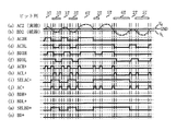
前述してきたブロック図の回路動作を図4、図5のタイミングチャートを参照して説明する。図4及び図5ともピット列は同じであり、その並びは、3Tのスペース、3Tのピット、3Tスペース、3Tピット、6Tスペース、2Tピット、5Tスペース、6Tピット、2Tスペース、5Tピット、・・・となっており、従来例で示した図8、図9とも同様である。従来例(図8、図9)では、6Tスペースと5Tスペースの間にある2Tピットや、6Tピットと5Tピットの間にある2Tスペース箇所において、強い符号間干渉により意図する二値化が行われなく、位相差検出パルスAC+、BD+にノイズ成分が乗った。 The circuit operation of the block diagram described above will be described with reference to the timing charts of FIGS. 4 and 5, the pit rows are the same, and the arrangement is 3T space, 3T pit, 3T space, 3T pit, 6T space, 6T space, 2T pit, 5T space, 6T pit, 2T space, 5T pit,. This is the same as in FIGS. 8 and 9 shown in the conventional example. In the conventional example (FIGS. 8 and 9), the intended binarization is performed due to strong intersymbol interference at the 2T pit between the 6T space and the 5T space, or at the 2T space portion between the 6T pit and the 5T pit. Unexpectedly, a noise component was added to the phase difference detection pulses AC + and BD +.
図4は、信号AC2(実線で示す)が信号BD2(破線で示す)に対して位相が進んでいる場合の各部の動作信号を示し、図5は、信号BD2が信号AC2に対して位相が進んでいる場合を示している。 FIG. 4 shows an operation signal of each part when the phase of the signal AC2 (shown by a solid line) is advanced with respect to the signal BD2 (shown by a broken line), and FIG. 5 shows that the signal BD2 is out of phase with the signal AC2. It shows the case of progress.
図4において、(c)は信号AC2を閾値レベルVHにて二値化した信号AC3H、(d)は信号AC2を閾値レベルVLにて二値化した信号AC3L、(e)は信号BD2を閾値レベルVHにて二値化した信号BD3H、(f)は信号BD2を閾値レベルVLにて二値化した信号BD3Lである。 4, (c) is a signal AC3H obtained by binarizing the signal AC2 at the threshold level V H , (d) is a signal AC3L obtained by binarizing the signal AC2 at the threshold level V L , and (e) is a signal BD2. Is a signal BD3H binarized at the threshold level V H , and (f) is a signal BD3L binarized from the signal BD2 at the threshold level V L.
ここで、符号間干渉が大きい6Tスペースと5Tスペースの間にある2Tピット部での各信号をみると、閾値レベルVHを用いた二値化回路104a(104c)では2Tピットを検出できているが、閾値レベルVLを用いた二値化回路104b(104d)では検出できていないのが分かる。また、同様に符号間干渉が大きい6Tピットと5Tピットの間にある2Tスペース部での各信号をみると、閾値レベルVHを用いた二値化回路では104a(104c)2Tピットを検出できていないが、閾値レベルVLを用いた二値化回路104b(104d)では検出できていることが分かる。
Here, looking at each signal in the 2T pit portion between the 6T space and the 5T space where the intersymbol interference is large, the
(g)は閾値VHにて二値化した信号AC3HとBD3Hとの位相比較を行い、信号ACが進み位相である際に生成される位相検出パルスACH+であり、(h)は閾値VLにて二値化した信号AC3LとBD3Lとの位相比較を行い、信号ACが進み位相である際に生成される位相検出パルスACL+である。 (G) is a phase comparison between the signals AC3H and BD3H binarized at the threshold value V H , and is the phase detection pulse ACH + generated when the signal AC is in the lead phase, and (h) is the threshold value V L. Is a phase detection pulse ACL + generated when the signal AC3L binarized at BD3L is compared in phase with the signal BD3L and the signal AC is in the lead phase.
(i)は、位相検出パルス選択回路202aの出力信号であるSELAC+であり、信号AC3Hの立ち下り時にHにセットされ、信号AC3Lの立ち上がり時にLにクリアされる。この信号SELAC+はデータセレクタ106aの選択信号となり、Hの時、信号ACH+を出力し、Lの時、信号ACL+を出力する。この結果、同図(j)の信号AC+が生成され、これが最終的な位相検出パルスとなる。この信号AC+は、各ピットの突入時と脱出時に位相パルスを出力しており、従来例(図8、図9)に示したような符号間干渉により二値化回路の誤動作が発生していないことが分かる。
(I) is SELAC + which is an output signal of the phase detection
尚、(k)は閾値VHにて二値化した信号AC3HとBD3Hとの位相比較を行い、信号BDが進み位相である際に生成される位相検出パルスBDH+であり、(l)は閾値VLにて二値化した信号AC3LとBD3Lとの位相比較を行い、信号BDが進み位相である際に生成される位相検出パルスBDL+であるが、このタイミングチャートは信号ACが進み位相の例であるため、信号BDH+、BDL+とも出力は無く常にLレベルである。 (K) is a phase comparison between the signals AC3H and BD3H binarized with the threshold value V H , and is a phase detection pulse BDH + generated when the signal BD is in the lead phase, and (l) is the threshold value. It compares the phase of the binarized signal AC3L and BD3L at V L, but the signal BD advances the phase detection pulse BDL + generated during a phase of the timing chart is the signal AC phase lead example Therefore, the signals BDH + and BDL + are not output and are always at the L level.
(m)は、位相検出パルス選択回路202bの出力信号であるSELBD+であり、信号BD3Hの立ち下り時にHにセットされ、信号BD3Lの立ち上がり時にLにクリアされる。本信号SELBD+はデータセレクタ106bの選択信号となり、Hの時、信号BDH+を出力し、Lの時、信号BDL+を出力するが、前述したように、このタイミングチャートは信号ACが進み位相の例であるため、信号BDH+、BDL+ともLレベルであるため、データセレクタ106bの出力である信号BD+(同図(n))は常にLレベルとなる。
(M) is SELBD + which is an output signal of the phase detection
このようにして得た位相検出パルスAC+とBD+は、従来と同様なローパスフィルタ(LPF)107a、107bと差動増幅器108によって、トラッキング誤差信号(TE)を得ることができる。
The phase detection pulses AC + and BD + obtained in this way can obtain a tracking error signal (TE) by the low-pass filters (LPF) 107a and 107b and the
図5は、信号BD2が信号AC2に対して位相が進んでいる場合の各部の動作信号を示しており、図4との相違点のみ説明する。 FIG. 5 shows an operation signal of each part when the phase of the signal BD2 is advanced with respect to the signal AC2, and only differences from FIG. 4 will be described.
位相検出パルスACH+(g)とACL+(h)は、AC信号が進み位相の場合に発生する信号であるため、この例では発生せず常にLレベルとなり、同様に、信号AC+(j)も常にLレベルである。その代わりに、位相検出パルスBDH+(k)とBDL+(l)に出力パルスが発生し、位相検出パルス選択信号SELBD+により選択され、最終的な位相検出パルスBD+(n)が生成される。 Since the phase detection pulses ACH + (g) and ACL + (h) are signals that are generated when the AC signal is in the lead phase, they are not generated in this example and are always at the L level. Similarly, the signal AC + (j) is always L level. Instead, output pulses are generated for the phase detection pulses BDH + (k) and BDL + (l), which are selected by the phase detection pulse selection signal SELBD +, and the final phase detection pulse BD + (n) is generated.
この信号BD+においても、各ピットの突入時と脱出時に位相パルスを出力しており、従来例(図8、図9)に示したような符号間干渉により二値化回路の誤動作が発生していないことが分かる。 Also in this signal BD +, a phase pulse is output when each pit enters and exits, and the binarization circuit malfunctions due to intersymbol interference as shown in the conventional example (FIGS. 8 and 9). I understand that there is no.
尚、上記した実施形態では、位相検出パルス選択回路において抵抗素子とコンデンサによる積分回路を用いて入力信号の立ち上がり、立ち下りを検出し、位相検出パルス選択信号を生成したが、別の遅延手段(例えばバッファ等の遅延)を利用することが可能である。 In the above-described embodiment, the phase detection pulse selection circuit detects the rising and falling edges of the input signal using an integration circuit including a resistance element and a capacitor, and generates the phase detection pulse selection signal. For example, a delay of a buffer or the like can be used.
また、この実施形態では、二値化回路の閾値電圧に二つの基準電圧発生回路120a、120bの出力する固定電圧VHとVLを用いているが、システムコントローラ等によりこの閾値電圧を微調整可能な形態とし、トラッキング誤差信号の品質が最も良くなるように当該閾値電圧を調整できるようにするのが望ましい。
In this embodiment, the fixed voltages V H and V L output from the two reference
101 分割受光素子
101a、101b、101c、101d 受光素子
102a、102b 加算器
103a、103b イコライザ
104a、104b、104c、104d 二値化回路
120a、120b 基準電圧発生回路
105 位相比較器
201a、201b 位相比較器
202a、202b 位相検出パルス選択回路
106a、106b データセレクタ
107a、107b ローパスフィルタ
108 差動増幅器
101 divided
Claims (3)
Priority Applications (1)
| Application Number | Priority Date | Filing Date | Title |
|---|---|---|---|
| JP2003423113A JP4201698B2 (en) | 2003-12-19 | 2003-12-19 | Tracking error signal detector |
Applications Claiming Priority (1)
| Application Number | Priority Date | Filing Date | Title |
|---|---|---|---|
| JP2003423113A JP4201698B2 (en) | 2003-12-19 | 2003-12-19 | Tracking error signal detector |
Publications (2)
| Publication Number | Publication Date |
|---|---|
| JP2005182927A JP2005182927A (en) | 2005-07-07 |
| JP4201698B2 true JP4201698B2 (en) | 2008-12-24 |
Family
ID=34783752
Family Applications (1)
| Application Number | Title | Priority Date | Filing Date |
|---|---|---|---|
| JP2003423113A Expired - Fee Related JP4201698B2 (en) | 2003-12-19 | 2003-12-19 | Tracking error signal detector |
Country Status (1)
| Country | Link |
|---|---|
| JP (1) | JP4201698B2 (en) |
Families Citing this family (1)
| Publication number | Priority date | Publication date | Assignee | Title |
|---|---|---|---|---|
| JP4579803B2 (en) | 2005-09-15 | 2010-11-10 | 東芝サムスン ストレージ・テクノロジー株式会社 | Optical disk device |
-
2003
- 2003-12-19 JP JP2003423113A patent/JP4201698B2/en not_active Expired - Fee Related
Also Published As
| Publication number | Publication date |
|---|---|
| JP2005182927A (en) | 2005-07-07 |
Similar Documents
| Publication | Publication Date | Title |
|---|---|---|
| US5808979A (en) | Tracking error signal detector | |
| US7400569B2 (en) | Optical disc with wobbled tracks and apparatus using this optical disc | |
| US20100188275A1 (en) | Signal processing device | |
| EP0817188A2 (en) | Apparatus for retrieving data from a storage device | |
| US6658054B1 (en) | Waveform equalizer and data reproducing apparatus using the same | |
| JP4561911B2 (en) | Laser drive device, optical device | |
| JP4317810B2 (en) | Optical disc recording / reproducing apparatus | |
| JP4201698B2 (en) | Tracking error signal detector | |
| JP4579803B2 (en) | Optical disk device | |
| JP4791335B2 (en) | Tracking error detection method and optical disk reproducing apparatus using the same | |
| JP4387422B2 (en) | Signal reproduction device | |
| JP4379253B2 (en) | Tracking error signal generation circuit | |
| JP4237305B2 (en) | Optical disk device | |
| US20040202070A1 (en) | Apparatus and method for generating tracking error signal and optical recording/reproducing system using same | |
| JP4268578B2 (en) | Optical disk device | |
| JP2006048880A (en) | Wobble signal detection method and wobble signal detector | |
| JP2010152951A (en) | Optical disk drive device | |
| JP4697096B2 (en) | Optical disk device | |
| WO2003098798A1 (en) | Slew rate limiting circuit and optical disc apparatus | |
| JP2007184049A (en) | Tracking error detection circuit | |
| JP2003303431A (en) | Tracking error detector | |
| JP2010041639A (en) | Phase-locked loop circuit, information reproduction device, electronic apparatus, and gain control method of the phase-locked loop circuit | |
| JP4446865B2 (en) | Information recording medium, synchronization signal generating method, information reproducing method, information reproducing device, information recording method, information recording device | |
| JP2005322325A (en) | Method and device for recording multivalue information, and method and device for reproducing multivalue information | |
| JP2006048841A (en) | Wobble signal detection circuit, optical disk device, and wobble signal detection method |
Legal Events
| Date | Code | Title | Description |
|---|---|---|---|
| A621 | Written request for application examination |
Free format text: JAPANESE INTERMEDIATE CODE: A621 Effective date: 20061117 |
|
| A977 | Report on retrieval |
Free format text: JAPANESE INTERMEDIATE CODE: A971007 Effective date: 20080229 |
|
| A131 | Notification of reasons for refusal |
Free format text: JAPANESE INTERMEDIATE CODE: A131 Effective date: 20080513 |
|
| A521 | Written amendment |
Free format text: JAPANESE INTERMEDIATE CODE: A523 Effective date: 20080709 |
|
| TRDD | Decision of grant or rejection written | ||
| A01 | Written decision to grant a patent or to grant a registration (utility model) |
Free format text: JAPANESE INTERMEDIATE CODE: A01 Effective date: 20080909 |
|
| A01 | Written decision to grant a patent or to grant a registration (utility model) |
Free format text: JAPANESE INTERMEDIATE CODE: A01 |
|
| A61 | First payment of annual fees (during grant procedure) |
Free format text: JAPANESE INTERMEDIATE CODE: A61 Effective date: 20081007 |
|
| FPAY | Renewal fee payment (event date is renewal date of database) |
Free format text: PAYMENT UNTIL: 20111017 Year of fee payment: 3 |
|
| FPAY | Renewal fee payment (event date is renewal date of database) |
Free format text: PAYMENT UNTIL: 20121017 Year of fee payment: 4 |
|
| FPAY | Renewal fee payment (event date is renewal date of database) |
Free format text: PAYMENT UNTIL: 20121017 Year of fee payment: 4 |
|
| FPAY | Renewal fee payment (event date is renewal date of database) |
Free format text: PAYMENT UNTIL: 20131017 Year of fee payment: 5 |
|
| LAPS | Cancellation because of no payment of annual fees |