JP4201450B2 - Tent mounting structure - Google Patents
Tent mounting structure Download PDFInfo
- Publication number
- JP4201450B2 JP4201450B2 JP2000037323A JP2000037323A JP4201450B2 JP 4201450 B2 JP4201450 B2 JP 4201450B2 JP 2000037323 A JP2000037323 A JP 2000037323A JP 2000037323 A JP2000037323 A JP 2000037323A JP 4201450 B2 JP4201450 B2 JP 4201450B2
- Authority
- JP
- Japan
- Prior art keywords
- tent
- main body
- tent main
- slide fastener
- entire length
- Prior art date
- Legal status (The legal status is an assumption and is not a legal conclusion. Google has not performed a legal analysis and makes no representation as to the accuracy of the status listed.)
- Expired - Fee Related
Links
Images


Landscapes
- Tents Or Canopies (AREA)
Description
【0001】
【発明の属する技術分野】
本発明は、例えば建築工事現場などにおいて雨よけなどのために設けられるテントの取り付け構造に関するものである。
【0002】
【従来の技術】
従来から、建築工事現場などにおいて雨よけなどのために設けられるテントはテントの周囲近傍適所に繋がれたロープを建築構造物の適所に結び付けて取り付けられているのが現状である。
【0003】
しかしながら、このようにテントの周囲近傍適所に繋がれたロープを建築構造物の適所に結び付けて取り付ける方法では、風が強いとテントが捲れ上がり、充分な雨よけ効果が得られないという問題があった。
【0004】
【発明が解決しようとする課題】
本発明はこのような課題を解決するもので、テントを建築構造物に対して強固に張ることができ、風が強くても捲れ上がることがないようにすることを目的とするものである。
【0005】
この課題を解決するために本発明は、正方形のテント本体部の内面に中心部から放射状に位置するように多数本のロープを取り付け、テント本体部の外周部近傍において各ロープにロープの長さ方向の任意の箇所で結合されるテント固定部材を設け、このテント固定部材に連結された引っ掛け手段をテント本体部の張設箇所に引っ掛けることによりテント本体部を建築構造物に対して張設するようにしたテントの取り付け構造であって、テント本体部の互いに直角な2つの側辺部において、この側辺部に近接する内面に側辺部から少し飛び出すようにスライドファスナーをこの側辺部の長さ方向ほぼ全長に亘って縫着にて取り付け、この側辺部に近接する外面に側辺部から少し飛び出し前記スライドファスナーを覆うようにこの側辺部の長さ方向ほぼ全長に亘って帯状の補助シートを縫着にて取り付け、この補助シートのテント本体部からの突出部内面に補助シートの長さ方向ほぼ全長に亘ってスライドファスナーと重ならないように面ファスナーを縫着にて取り付け、またテント本体部の前記互いに直角な2つの側辺部を除く残りの直角な2つの側辺部において、この側辺部に近接する内面に側辺部から少し飛び出すように前記スライドファスナーと対となるスライドファスナーをこの側辺部の長さ方向ほぼ全長に亘って縫着にて取り付けるとともにこの側辺部に近接する外面に前記面ファスナーと対となる面ファスナーをこの側辺部の長さ方向ほぼ全長に亘って縫着にて取り付けてなることを要旨とするものである。
【0006】
この構成により、テント本体部の内面に中心部から放射状に位置するように多数本のロープを縫着などにより取り付け、テント本体部の外周部近傍において各ロープにテント固定部材を結合させ、このテント固定部材に連結されたフックなどの引っ掛け手段をテント本体部の張設場所に引っ掛けることにより、テントを建築構造物に対して容易且つ強固に張設することができる。また、このテントを傾斜状態で張設することができ、テントの上の雨水をテントの外に落とすことができ。さらに、テント本体部の外周部適所に浮き上がり防止用錘を取り付けることにより、テント本体部の外周部の風によるばたつきを防止し、風が強くても捲れ上がることがない。
【0007】
【発明の実施の形態】
以下、本発明の実施の形態について、図面に基づいて説明する。
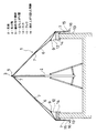
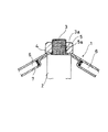
先ず、図1〜図7に示す第1の実施の形態について説明すると、1は帆布などの繊維基布を素材とし、吸水防止加工が施されてなる正方形のテント本体部で、このテント本体部1の中心部に折り畳み式の支柱2の上端に突出する支え軸3を下方より挿入するための孔部4が設けられている。5は前記孔部4から上方に突出する支え軸3の外面の雄ねじ部3aに螺合する雌ねじ孔5aを持つ締め付け部材で、この締め付け部材5を支え軸3の上端より螺合させることにより、支柱2の上端と締め付け部材5との間で前記孔部4周辺を挟むようになっている。6は前記テント本体部1の内面側においてテント本体部1の中心部から放射状に位置するように設けられた多数本のロープで、この各ロープ6の一端はテント本体部1の中心部の前記孔部4の周りに補強布7を当てて縫着することにより支持され、他端もテント本体部1の外周部内面に補強布7を当てて縫着することにより支持され、さらにロープ6の長さ方向中央部もテント本体部1の内面に補強布7を当てて縫着することにより支持されている。ところで、前記テント本体部1の外周部には各側辺部に沿って適当間隔おきにハトメ孔8が設けられている。9は前記ロープ6の長さ方向他端近傍、つまり前記テント本体部1の外周部近傍において、ロープ6の長さ方向任意の箇所に固定される例えば金属製の環状のテント固定部材で、図4および図5に示すように一個所で切り離されていてロープ6の長さ方向に自在に移動できるようになっており、その切り離し端部に設けられた2つの突出片10,10間を近づけることにより環状のテント固定部材9の内径が縮まり、環状のテント固定部材9の内面両側に一体に設けた凸部11がこのテント固定部材9に挿通されたロープ6に圧接し、テント固定部材9がロープ6と結合されるようになっている。12は前記テント固定部材9の2つの突出片10,10に形成された孔部10a,10aに一端部が係止するS字状のフックで、このフック12の他端部をテント張設部の周辺部に位置する適当な固定部に引張りながら係止させることによりその引張り力がフック12を介してテント固定部材9側に伝わり、それによりテント固定部材9の内径が縮まってロープ6を掴み、ロープ6を介してテント本体部1を張設することになる。
【0008】
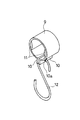
図面に示す実施の形態ではコンクリート造りの建物の屋上でテント本体部1の中心部を前記支柱2で持ち上げ、建物の屋上の立ち上がり壁13の上端に立ち上がり壁13の周囲に適当間隔おきに万力14を取り付け、この万力14に前記フック12の他端部を係止させてテント本体部1を中心が高くなるような断面山型に張設している。ところで、前記屋上が上から見てほぼ正方形で1枚のテント本体部1で覆われる程度の大きさであればテント本体部1の外周部の各側辺部をそれぞれ屋上の立ち上がり壁13の上端に係止させれば良いが、屋上が大きい場合はテント本体部1を複数枚繋ぎ合わせるようにすれば良い。そして、屋上を覆うように張設された前記テント本体部1にはその外周部のハトメ孔8にS字状のフック15を介して立ち上がり壁13の外側で浮き上がり防止用錘16を取り付け、前記立ち上がり壁13の外側に被るテント本体部1の外周部の風によるばたつきを防止している。具体的には前記浮き上がり防止用錘16としては袋状の横長のタンク17を用い、このタンク17の端部に開閉自在な水などの注入口18を設け、この注入口18よりタンク17の中に水などを注入することにより浮き上がり防止用錘16が完成する。なお、タンク17の上端には水平方向に前記フック15を掛けるためのハトメ孔19が形成されている。このように構成された浮き上がり防止用錘16は前記テント本体部1の外周部を形成する各辺にそれぞれ複数箇所設けられる。
【0009】
次に、図8に示す第2の実施の形態について説明すると、この実施の形態はコンクリート造りの建物の屋上の直下に位置する部屋のバルコニー20の立ち上がり壁21の上端と屋上の立ち上がり壁13の上端との間をテント本体部1で覆ったもので、テント本体部1は前記第1の実施の形態のような支柱2で支持させずに、テント本体部1の1つの側辺部をバルコニー20の立ち上がり壁21の上端に前記第1の実施の形態と同様にロープ6、テント固定部材9、フック12を介して万力14に支持させるとともにテント本体部1の前記1つの側辺部に対向する側辺部を屋上の立ち上がり壁13の上端にロープ6、テント固定部材9、フック12を介して万力14に支持させ、テント本体部1を屋上の立ち上がり壁13から下向きに傾斜させて張設している。なお、テント本体部1の中心部の孔部4は適当なカバー(図示せず)により閉じられる。ところで、バルコニー20の正面から見た水平方向の長さが短い場合はテント本体部1の1つの側辺部に対して直角な2つの側辺部も同様にして建物の適当な箇所に支持させれば良いが、バルコニー20の正面から見た水平方向の長さが長くなれば、テント本体部1を複数枚繋ぎ合わせるようにしても良い。
【0010】
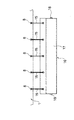
図9〜図12に示す第3の実施の形態はテント本体部1を複数枚繋ぎ合わせる場合であって、1枚のテント本体部1の互いに直角な2つの側辺部22,22には側辺部22に近接する内面に側辺部22から少し飛び出すようにスライドファスナー23aを各側辺部22の長さ方向ほぼ全長に亘って縫着するとともに、側辺部22に近接する外面に前記スライドファスナー23aを覆うように各側辺部22の長さ方向ほぼ全長に亘ってテント本体部1と同様の素材からなる帯状の補助シート24を縫着し、この補助シート24のテント本体部1からの突出部内面に補助シート24の長さ方向ほぼ全長に亘って前記スライドファスナー23aと重ならないように面ファスナー25aを縫着してある。また、テント本体部1の前記互いに直角な2つの側辺部22,22を除く残りの互いに直角な2つの側辺部26,26には側辺部26に近接する内面に側辺部26から少し飛び出すように前記スライドファスナー23aと対となるスライドファスナー23bを各側辺部26の長さ方向ほぼ全長に亘って縫着するとともに、側辺部26に近接する外面に前記面ファスナー25aと対となる面ファスナー25bを側辺部26の長さ方向ほぼ全長に亘って縫着してある。このような構成を備えることによって、複数枚のテント本体部1を互いに繋ぎ合わせる場合、隣り合う一方のテント本体部1の前記側辺部22と他方のテント本体部1の前記側辺部26を近づけ、前記スライドファスナー23aおよびスライドファスナー23bの噛み合いによって隣り合う両テント本体部1,1が互いに結合され、前記面ファスナー25aおよび面ファスナー25bの噛み合いによって前記補助シート24により前記スライドファスナー23a,23bによる結合部が外側から覆われることになる。このような手順により複数枚のテント本体部1を繋ぎ合わすことができる。
【0011】
ところで、本発明は以上述べた実施の形態において使用されるテント固定部材9や万力14は図面に示されるものに限定されるものではなく、また複数枚のテント本体部1を繋ぎ合わせる手段も図面に示されるものに限定されるものではない。また、前記第1の実施の形態において、テント本体部1の中心部の孔部4に支柱2の上端に突出する支え軸3を下方より挿入させ、この支え軸3の外面の雄ねじ部3aに締め付け部材5を螺合させるて支柱2の上端と締め付け部材5との間で前記孔部4周辺を挟むようになっているが、支柱2の上端に雌ねじ部を形成し、この支柱2の上端をテント本体部1の中心部の孔部4周辺内面に当て、締め付け部材5側に支柱2の上端の雌ねじ部に螺合する雄ねじ部を備えて、この雄ねじ部を支柱2上端の雌ねじ部に螺合させることにより支柱2の上端と締め付け部材5との間で前記孔部4周辺を挟むようにしても良い。さらに、テント本体部1の張設場所も図面に示されるものに限定されるものではなく、テント本体部1の端部を万力14などを介して係止させる場所さえあれば必要な場所にテント本体部1を容易に張設することができる。なお、テント本体部1の張設場所にフックなどを引っ掛ける箇所が既にあれば、万力14を使用する必要がない。
【0012】
【発明の効果】
以上のように本発明によれば、テント本体部の内面に中心部から放射状に位置するように多数本のロープを縫着などにより取り付け、テント本体部の外周部近傍において各ロープにテント固定部材を結合させ、このテント固定部材に連結されたフックなどの引っ掛け手段をテント本体部の張設場所に引っ掛けることにより、テントを建築構造物に対して容易且つ強固に張設することができる。また、このテントを傾斜状態で張設することができ、テントの上の雨水をテントの外に落とすことができ。さらに、テント本体部の外周部適所に浮き上がり防止用錘を取り付けることにより、テント本体部の外周部の風によるばたつきを防止し、風が強くても捲れ上がることがない。
【図面の簡単な説明】
【図1】本発明の第1の実施の形態におけるテント本体部の底面図である。
【図2】同テント本体部の張設状態を示す断面図である。
【図3】同支柱によるテント本体部の持ち上げ部の拡大断面図である。
【図4】同テント固定部材の正面図である。
【図5】同テント固定部材の斜視図である。
【図6】同浮き上がり防止用錘をテント本体部に取り付けた状態を示す正面図である。
【図7】同浮き上がり防止用錘をテント本体部に取り付けた状態を示す側面図である。
【図8】本発明の第2の実施の形態におけるテント本体部の張設状態を示す断面図である。
【図9】本発明の第3の実施の形態におけるテント本体部の平面図である。
【図10】同テント本体部のA部拡大断面図である。
【図11】同テント本体部のB部拡大断面図である。
【図12】同テント本体部同士を繋いだ状態を示す要部拡大断面図である。
【符号の説明】
1 テント本体部
2 支柱
3 支え軸
4 孔部
5 締め付け部材
6 ロープ
8 ハトメ孔
9 テント固定部材
10 突出片
10a 孔部
11 凸部
12 フック
13 立ち上がり壁
14 万力
15 フック
16 浮き上がり防止用錘
20 バルコニー
21 立ち上がり壁
22 側辺部
23a,23b スライドファスナー
24 補助シート
25a,25b 面ファスナー
26 側辺部[0001]
BACKGROUND OF THE INVENTION
The present invention relates to a tent mounting structure provided for preventing rain in a construction site, for example.
[0002]
[Prior art]
Conventionally, a tent provided for preventing rain in a construction site or the like is currently attached by connecting a rope connected to an appropriate position in the vicinity of the tent to an appropriate position of a building structure.
[0003]
However, the method of attaching the ropes connected to the appropriate positions in the vicinity of the tent in this way to the appropriate positions of the building structure has a problem that the tent is swollen if the wind is strong and sufficient rain protection effect cannot be obtained. .
[0004]
[Problems to be solved by the invention]
The present invention solves such a problem, and an object of the present invention is to make it possible to firmly stretch a tent against a building structure so that the tent does not rise even if the wind is strong.
[0005]
In order to solve this problem, the present invention attaches a number of ropes to the inner surface of a square tent main body so as to be located radially from the center, and the length of the rope is attached to each rope near the outer periphery of the tent main body. A tent fixing member to be coupled at an arbitrary position in the direction is provided, and the tent main body is stretched with respect to the building structure by hooking the hook means connected to the tent fixing member to the tensioning portion of the tent main body. In the tent mounting structure as described above, in the two side parts perpendicular to each other of the tent main body part, the slide fastener is placed on the side part so as to slightly protrude from the side part to the inner surface close to the side part. It is attached by sewing over almost the entire length, and the length of this side part protrudes slightly from the side part to the outer surface close to this side part and covers the slide fastener. A belt-like auxiliary sheet is attached to the entire length of the auxiliary sheet by sewing, and a hook-and-loop fastener is attached to the inner surface of the protruding portion of the auxiliary sheet from the tent main body so as not to overlap the slide fastener over the entire length of the auxiliary sheet. At the other two right side portions excluding the two right side portions of the tent main body portion, the tent main body portion protrudes slightly from the side portions to the inner surface close to the side portions. A slide fastener paired with the slide fastener is attached by sewing over substantially the entire length of the side portion, and a hook-and-loop fastener paired with the surface fastener is attached to the outer surface close to the side portion. it is an gist to become attached by sewing over the length substantially the entire length of the side portions.
[0006]
With this configuration, a large number of ropes are attached to the inner surface of the tent main body so as to be radially located from the center by sewing or the like, and a tent fixing member is coupled to each rope near the outer periphery of the tent main body. By hooking hooking means, such as a hook, connected to the fixing member, at the place where the tent main body is stretched, the tent can be easily and firmly stretched against the building structure. In addition, this tent can be stretched in an inclined state, and rain water on the tent can be dropped out of the tent. Furthermore, by attaching a lifting prevention weight to an appropriate position on the outer peripheral part of the tent main body part, flapping by the wind on the outer peripheral part of the tent main body part is prevented, and even if the wind is strong, it will not swell.
[0007]
DETAILED DESCRIPTION OF THE INVENTION
Hereinafter, embodiments of the present invention will be described with reference to the drawings.
First, the first embodiment shown in FIGS. 1 to 7 will be described.
[0008]
In the embodiment shown in the drawings, the center of the tent
[0009]
Next, a second embodiment shown in FIG. 8 will be described. In this embodiment, the upper end of the rising
[0010]
The third embodiment shown in FIG. 9 to FIG. 12 is a case where a plurality of
[0011]
By the way, the present invention is not limited to the
[0012]
【The invention's effect】
As described above, according to the present invention, a large number of ropes are attached to the inner surface of the tent main body portion radially from the center portion by sewing or the like, and the tent fixing member is attached to each rope in the vicinity of the outer peripheral portion of the tent main body portion. , And hooking means such as a hook connected to the tent fixing member is hooked on the tent main body portion where the tent body is stretched, so that the tent can be easily and firmly stretched to the building structure. In addition, this tent can be stretched in an inclined state, and rain water on the tent can be dropped out of the tent. Furthermore, by attaching a lifting prevention weight to an appropriate position on the outer peripheral part of the tent main body part, flapping by the wind on the outer peripheral part of the tent main body part is prevented, and even if the wind is strong, it will not swell.
[Brief description of the drawings]
FIG. 1 is a bottom view of a tent main body according to a first embodiment of the present invention.
FIG. 2 is a sectional view showing a tensioned state of the tent body.
FIG. 3 is an enlarged cross-sectional view of a lifting portion of the tent main body portion by the support column.
FIG. 4 is a front view of the tent fixing member.
FIG. 5 is a perspective view of the tent fixing member.
FIG. 6 is a front view showing a state where the lifting prevention weight is attached to the tent main body.
FIG. 7 is a side view showing a state in which the lifting prevention weight is attached to the tent body.
FIG. 8 is a cross-sectional view showing a stretched state of a tent main body portion in a second embodiment of the present invention.
FIG. 9 is a plan view of a tent main body according to a third embodiment of the present invention.
FIG. 10 is an enlarged sectional view of part A of the tent main body part.
FIG. 11 is an enlarged cross-sectional view of a B part of the tent main body part.
FIG. 12 is an enlarged cross-sectional view of a main part showing a state where the tent main body parts are connected to each other.
[Explanation of symbols]
DESCRIPTION OF
Claims (1)
Priority Applications (1)
| Application Number | Priority Date | Filing Date | Title |
|---|---|---|---|
| JP2000037323A JP4201450B2 (en) | 2000-02-16 | 2000-02-16 | Tent mounting structure |
Applications Claiming Priority (1)
| Application Number | Priority Date | Filing Date | Title |
|---|---|---|---|
| JP2000037323A JP4201450B2 (en) | 2000-02-16 | 2000-02-16 | Tent mounting structure |
Publications (2)
| Publication Number | Publication Date |
|---|---|
| JP2001227169A JP2001227169A (en) | 2001-08-24 |
| JP4201450B2 true JP4201450B2 (en) | 2008-12-24 |
Family
ID=18561225
Family Applications (1)
| Application Number | Title | Priority Date | Filing Date |
|---|---|---|---|
| JP2000037323A Expired - Fee Related JP4201450B2 (en) | 2000-02-16 | 2000-02-16 | Tent mounting structure |
Country Status (1)
| Country | Link |
|---|---|
| JP (1) | JP4201450B2 (en) |
Families Citing this family (3)
| Publication number | Priority date | Publication date | Assignee | Title |
|---|---|---|---|---|
| KR100997147B1 (en) * | 2008-07-21 | 2010-11-30 | 배진산업주식회사 | Means to connect a plurality of tents for enlarged use |
| JP6151833B1 (en) * | 2016-09-08 | 2017-06-21 | 啓子 森 | Tent rainwater drainage |
| KR102181644B1 (en) * | 2019-02-13 | 2020-11-23 | 동서대학교 산학협력단 | movable type scattering dust cover on construction site |
-
2000
- 2000-02-16 JP JP2000037323A patent/JP4201450B2/en not_active Expired - Fee Related
Also Published As
| Publication number | Publication date |
|---|---|
| JP2001227169A (en) | 2001-08-24 |
Similar Documents
| Publication | Publication Date | Title |
|---|---|---|
| KR200312123Y1 (en) | A collapsible tent with strengthen structure | |
| US4825892A (en) | Instantly stable, quickly erectable and quickly collapsible portable structure | |
| US6994099B2 (en) | Shelter with twist tight canopy and method for assembling same | |
| US9482027B2 (en) | Mechanisms for shelter attachments | |
| US5771912A (en) | Attachment device for erecting a tent | |
| US7178537B2 (en) | Ring and pole connector assembly for a tent corner | |
| US7757439B1 (en) | Fabric structures with tensioner and tensioner device | |
| US5778613A (en) | Canopy structures | |
| JP4201450B2 (en) | Tent mounting structure | |
| US214996A (en) | Improvement in tents | |
| FI65539C (en) | IHOPFAELLBART TAELT MED UTVAENDIGT STATIV | |
| KR20100128873A (en) | Connecting device for tent | |
| KR200496553Y1 (en) | Apparatus for fixing tarp | |
| US5860196A (en) | Grommet stress reducer | |
| JPH03180677A (en) | Tent | |
| CN221422874U (en) | Tent with cover | |
| KR102220881B1 (en) | rotary type flag ring for fixing flagpole rope | |
| US10584512B2 (en) | Device for tensioning a fabric of a tent | |
| KR960008869Y1 (en) | Device for fastening a fly on a tent | |
| JPH026194Y2 (en) | ||
| JPH0821106A (en) | Construction site tent sheet, construction site tent, and construction execution method | |
| KR200278489Y1 (en) | Marquee Type Tent Top Portion Cap Structure | |
| KR20140003671U (en) | Tarp | |
| JP2001107604A (en) | Tarpaulin and tarpaulin construction tape | |
| JP2516259Y2 (en) | Sheet for temporary roof |
Legal Events
| Date | Code | Title | Description |
|---|---|---|---|
| A621 | Written request for application examination |
Free format text: JAPANESE INTERMEDIATE CODE: A621 Effective date: 20061227 |
|
| A977 | Report on retrieval |
Free format text: JAPANESE INTERMEDIATE CODE: A971007 Effective date: 20080612 |
|
| A131 | Notification of reasons for refusal |
Free format text: JAPANESE INTERMEDIATE CODE: A131 Effective date: 20080617 |
|
| A521 | Written amendment |
Free format text: JAPANESE INTERMEDIATE CODE: A523 Effective date: 20080804 |
|
| TRDD | Decision of grant or rejection written | ||
| A01 | Written decision to grant a patent or to grant a registration (utility model) |
Free format text: JAPANESE INTERMEDIATE CODE: A01 Effective date: 20080909 |
|
| A01 | Written decision to grant a patent or to grant a registration (utility model) |
Free format text: JAPANESE INTERMEDIATE CODE: A01 |
|
| A61 | First payment of annual fees (during grant procedure) |
Free format text: JAPANESE INTERMEDIATE CODE: A61 Effective date: 20081007 |
|
| R150 | Certificate of patent or registration of utility model |
Free format text: JAPANESE INTERMEDIATE CODE: R150 |
|
| FPAY | Renewal fee payment (event date is renewal date of database) |
Free format text: PAYMENT UNTIL: 20111017 Year of fee payment: 3 |
|
| FPAY | Renewal fee payment (event date is renewal date of database) |
Free format text: PAYMENT UNTIL: 20141017 Year of fee payment: 6 |
|
| R250 | Receipt of annual fees |
Free format text: JAPANESE INTERMEDIATE CODE: R250 |
|
| LAPS | Cancellation because of no payment of annual fees |