JP4201413B2 - Light source device for simplified endoscope - Google Patents
Light source device for simplified endoscope Download PDFInfo
- Publication number
- JP4201413B2 JP4201413B2 JP36829998A JP36829998A JP4201413B2 JP 4201413 B2 JP4201413 B2 JP 4201413B2 JP 36829998 A JP36829998 A JP 36829998A JP 36829998 A JP36829998 A JP 36829998A JP 4201413 B2 JP4201413 B2 JP 4201413B2
- Authority
- JP
- Japan
- Prior art keywords
- light source
- source device
- endoscope
- operation unit
- light
- Prior art date
- Legal status (The legal status is an assumption and is not a legal conclusion. Google has not performed a legal analysis and makes no representation as to the accuracy of the status listed.)
- Expired - Fee Related
Links
Images


Landscapes
- Arrangement Of Elements, Cooling, Sealing, Or The Like Of Lighting Devices (AREA)
- Endoscopes (AREA)
- Instruments For Viewing The Inside Of Hollow Bodies (AREA)
Description
【0001】
【発明の属する技術分野】
この発明は、ライトガイドの入射端部が操作部に配置された簡易型内視鏡の光源装置に関する。
【0002】
【従来の技術】
操作部に照明用の発光体を取り付けるようにしたいわゆる簡易型内視鏡には、一般に、豆電球と乾電池を内蔵した光源ユニットが操作部に着脱自在に取り付けられるようになっている。
【0003】
そのような、簡易型内視鏡と光源ユニットは共に外部から内部に水が入らない水密構造に構成して、使用後に消毒液中に浸漬できるようにする必要がある。そして、より完全な感染防止策として、エチレンオキサイドガス滅菌が行えることが望ましい。
【0004】
そのようなガス滅菌装置内では、先ず空気が排気されて一時的に真空に近い環境になるので、内視鏡を単純な水密構造にすると、湾曲部を被覆するゴムチューブが膨らんで破裂してしまう恐れがある。
【0005】
そこで従来は、内部圧力が外部より高くなったときに内部圧力を外部に逃がすための、リリーフバルブを設ける等の対策を施していた。
【0006】
【発明が解決しようとする課題】
簡易型内視鏡の光源装置は、内蔵されている電池を交換する必要が生じたときやランプ切れが発生した時などには、それらの交換をするための蓋を開ける必要があるが、光源装置自体が水密に構成されていると、蓋を開けようとする際に内部が陰圧になるため、容易に蓋を開けることができない場合が少なくない。
【0007】
上述のようなリリーフバルブが設けられたものでは、内部圧力が外部より高くなったときに内部圧力を外部に逃がすことはできるが、内部圧力が外部より低くなる現象を緩和することはできない。
【0008】
そこで本発明は、水密構造でありながら、内部圧力と外部圧力との関係がどのように変化しても、内部圧力が外部圧力に追随して変化して、内外圧力差に起因する不都合が発生しない簡易型内視鏡の光源装置を提供することを目的とする。
【0009】
【課題を解決するための手段】
上記の目的を達成するため、本発明の簡易型内視鏡の光源装置は、照明光を伝送するライトガイドの入射端部が操作部に配置された簡易型内視鏡に照明光を供給するため、上記操作部に対して着脱自在に設けられ、且つ水密に構成された簡易型内視鏡の光源装置において、光源装置の内部と外部とを連通させる通気路を形成して、その通気路を塞ぐように通気性はあるが通水性のない多孔質部材を設けたことを特徴とする。
【0010】
なお、上記通気路が、内部と大気とを連通させる第1の通気路と、上記操作部に取り付けられた状態において内部と上記操作部内とを連通させる第2の通気路とを含んでおり、その各通気路に上記多孔質部材が設けられていてもよい。
【0011】
また、内部に、光源ランプとその発光エネルギー源となる電池とが配置されていてもよく、上記の光源ランプ又は電池を交換するために開閉される蓋体が螺合により取り付けられていてもよい。
【0012】
【発明の実施の形態】
図3は、簡易型内視鏡の操作部2に光源ユニット30が取り付けられた状態を示しており、操作部2は、可撓管によって外装された挿入部1の基端側に連結されている。操作部2の握り部3と挿入部1との間には、鉗子挿入部4が突出して設けられている。
【0013】
操作部2の握り部3より上の操作機構部5には、挿入部1内に挿通された鉗子チャンネル(図示せず)を通しての吸引操作を行うための吸引操作弁6と、挿入部1の先端部分に形成された湾曲部(図示せず)を遠隔的に湾曲操作するための湾曲操作レバー7が前面と後面に配置され、接眼部8が上面に突設されている。
【0014】
被写体を照明するためのライトガイドファイババンドル9は、入射端部が操作機構部5内に配置され、挿入部1内と操作部2の握り部3内を通って、射出端部は挿入部1の先端に配置されている。
【0015】
そして、ライトガイドファイババンドル9に対して照明光を供給するための細長い光源ユニット30が、操作機構部5の側面部分に着脱自在に取り付けられている。
【0016】
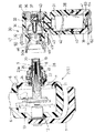
図1は、操作部2から光源ユニット30が取り外された状態の断面を拡大して示しており、図2は操作部2に光源ユニット30が連結された状態の拡大断面図である。
【0017】
操作部2の操作機構部5部分を外装する本体ケース11は、プラスチック製である。湾曲操作レバー7を支持する軸受筒12と吸引操作弁6は、本体ケース11に穿設された貫通孔に嵌挿されて、各々そこで水密にシールされている。軸受筒12と吸引操作弁6の基部は各々操作部2内のフレーム13に固定されている。
【0018】
本体ケース11に大きく形成された側面開口には蓋体15が嵌め込まれ、その嵌合面にはシール用のOリング16が装着されていて、隙間から内部に水が侵入しないようになっている。なお、Oリング16は装着されることによって潰されるが、図には潰される前の自然状態の断面が図示されている(以下、同じ)。
【0019】
蓋体15の中央部分に形成された孔の中心軸位置には、基部が操作部2内のフレーム13に固定された支持筒17が配置されている。そして、支持筒17にネジ止め連結されたライトガイド取付筒18が外方に突出していて、そのライトガイド取付筒18の中心軸位置に、ライトガイドファイババンドル9の入射端部がネジ止め固定されている。
【0020】
ライトガイド取付筒18の突出端側には、先端部分に凹凸レンズ20が水密に接合された筒状のレンズ取付筒19が、キャップ状に被せられて螺合固定されていて、それによって、凹凸レンズ20がライトガイドファイババンドル9の入射端面に近接して対向する位置に位置決めされている。
【0021】
支持筒17とライトガイド取付筒18との接続部においてその周りを囲んで配置されたOリング受け枠22は、外面において蓋体15の中央の孔と嵌合しており、その嵌合部にシール用のOリング24が装着されていて、隙間から内部に水が侵入しないようになっている。
【0022】
また、レンズ取付筒19からOリング受け枠22にまたがる部分を囲んで配置された接続筒23は、基部が蓋体15の孔の内面にネジ止め固定されていて、中間部分の外周面には雄ネジ23aが螺設され、それより先側の外周面は次第に細くなるテーパ面に形成されていて、そのテーパ面の途中にシール用のOリング26が装着されている。
【0023】
接続筒23の内周面とレンズ取付筒19の外周面との間には環状に隙間が形成されていて、その隙間が、操作部2の内部と外部を連通させる通気路28になっている。
【0024】
このようにして、操作部2は、通気路28部分を除いて他の全ての部分は外部から水が侵入しない水密構造に構成されている。挿入部1が同様に水密構造に形成されていることは勿論である。
【0025】
したがって、光源ユニット30が取り付けられていない内視鏡だけの状態では、通気路28によって内視鏡の内部と外部とが連通しているので、エチレンオキサイドガス滅菌器に入れて真空の環境に置かれても、内視鏡を構成する柔軟部分の破裂事故などは発生しない。
【0026】
光源ユニット30は、全体としてL字形の筒状に形成されており、その本体ケース31はプラスチック製である。そして、その曲がり部に、光源ランプ32がランプソケット33に取り付けられて配置されている。
【0027】
光源ランプ32は、L字状筒の短筒の軸線上に配置されていて、光源ランプ32から放射された照明光を短筒の軸線上に収束させるための反射鏡34が、光源ランプ32を囲むようにランプソケット33に取り付けられている。
【0028】
ランプソケット33の後方には、本体ケース31に開口が形成されていて、その開口口元にランプ室蓋35が着脱自在に螺合している。ランプ室蓋35と本体ケース31との嵌合面には、シール用のOリング36が装着されていて、隙間から内部に水が侵入しないようになっている。
【0029】
また、ランプ室蓋35とランプソケット33との間には圧縮コイルスプリング37が介装されていて、ランプソケット33と反射鏡34を弾力的に固定している。
【0030】
L字状の本体ケース31の長筒側の内部には、電池38が収容されている。電池38としては、乾電池または充電可能なカドニカ電池等のいずれを用いてもよい。
【0031】
本体ケース31の電池収容部の端部開口部には、プラスチック製の電池室蓋39が着脱自在に螺合されている。両者の境界面にはシール用のOリング40が装着されていて、隙間から内部に水が侵入しないようになっており、電池室蓋39を本体ケース31から取り外せば、電池38を交換することができる。
【0032】
41と42は、電池室蓋39と本体ケース31内に配置された負極側電極、43は本体ケース31内に配置された正極側電極であり、各々リード線43を介して光源ランプ32に接続されている。
【0033】
なお、その配線の途中には光源ランプ32への通電をオンオフ操作するためのスイッチが設けられているが、その図示は省略されている。そのスイッチ部分も、外部から内部に水が侵入しないように水密にシールされている。
【0034】
本体ケース31の短筒側の端部開口部には、操作部2に設けられた接続筒23のテーパ面に係合する形状のテーパ状開口部を有する接続筒受け筒46が、内側からナット47で締め付け固定されている。
【0035】
そして、接続筒受け筒46と本体ケース31との嵌合面には、シール用のOリング48が装着されていて、隙間から内部に水が侵入しないようになっている。また、接続筒受け筒46の内端部には、平行平面状の透明板49が水密に接合されている。
【0036】
このようにして、光源ユニット30は、全ての部分において外部から水が侵入しない水密構造に構成されている。したがって、操作部2に取り付けられていない光源ユニット30だけを単体で消毒液等に浸漬しても、浸水事故の恐れがない。また、光源ユニット30は、外壁に柔軟な部分がないので、エチレンオキサイドガス滅菌器内に入れても、破裂事故などは発生しない。
【0037】
接続筒受け筒46の外周側には、接続筒23の雄ネジ23aに螺合する雌ネジ50aが形成された締め付け輪50が軸方向に抜け出さないように取り付けられている。
【0038】
したがって、図1に示される状態から光源ユニット30を操作部2側に接近させて、接続筒23と接続筒受け筒46のテーパ面どうしを密着させ、締め付け輪50の雌ネジ50aを接続筒23の雄ネジ23aに締め込めば、図2に示されるように、光源ユニット30が操作部2に接続された状態になる。
【0039】
そのとき、接続筒23のテーパ面に装着されたOリング26が接続筒受け筒46によって潰されるので、接続部内には外部から水が侵入しない。そして、通気路28は、そのOリング26でシールされた接続部の内側に開口しているので、光源ユニット30が操作部2に取り付けられた状態で装置全体を消毒液等に浸漬しても、消毒液は装置内に一切侵入しない。
【0040】
このようにして光源ユニット30が操作部2に取り付けられると、光源ランプ32から放射された照明光が、反射鏡34で反射されたあと、透明板49及び凹凸レンズ20を通過してライトガイドファイババンドル9の入射端面に集光し、ライトガイドファイババンドル9に入射する。
【0041】
このように構成された簡易型内視鏡の光源装置の電池室蓋39には、通気性はあるが通水性のない多孔質シート61を間に挟み込む状態に、押さえ蓋62が螺合により取り付けられている。多孔質シート61は、例えば多数の微小な連続気泡を有する四フッ化エチレン樹脂等によって形成されている。
【0042】
電池室蓋39と押さえ蓋62には、電池38が収容されている内部と外部の大気との間を連通させる通気孔63,64(第1の通気路)が穿設されており、多孔質シート61はその通気孔63,64を途中で塞ぐ状態に配置されている。
【0043】
その結果、光源ユニット30は気密性は保たれているものの、内部と大気との間の通気は行われる。したがって、光源ユニット30の内部の圧力は周囲の環境圧力の変化に追従して変化し、電池38を交換する際には電池室蓋39を楽に取り外すことができる等、内外圧力差に起因する不都合が発生しない。
【0044】
内視鏡操作部2の接続筒23が差し込まれる光源ユニット30の接続筒受け筒46には、奥の部分(操作部2に光源ユニット30が連結された状態の時に、接続筒23側のOリング26より奥に位置する内部部分)にも、光源ユニット30の内部と外部とを連通させる通気孔65(第2の通気路)が穿設されていて、通気性はあるが通水性のない多孔質シート66がその通気孔65を塞ぐ状態に取り付けられている。
【0045】
その結果、操作部2と光源ユニット30とが連結されていない状態では、この通気孔65の機能は電池室蓋39に形成された通気孔63,64と全く同じである。なお、この通気孔65と電池室蓋39に形成された通気孔63,64とは、光源ユニット30の内部空間を介して連通している。
【0046】
しかし、操作部2に光源ユニット30が連結された状態においては、この通気孔65と多孔質シート66及び操作部2側の通気路28を介して操作部2内と光源ユニット30内とが通気性を有する状態になるので、操作部2内も電池室蓋39に形成された通気孔63,64を介して大気と通気性を有することになり、光源ユニット30内の圧力と共に内視鏡内の圧力も周囲の環境圧力の変化に追従して変化し、内外圧力差に起因する不都合が発生しない。
【0047】
なお、本発明は上記実施の形態に限定されるものではなく、例えば光源ユニット30内と大気との間の通気孔は、電池室蓋39に限らず光源ユニット30のどの部分に形成してもよい。
【0048】
【発明の効果】
本発明によれば、光源装置の内部と外部とを連通させる通気路を形成して、その通気路を塞ぐように通気性はあるが通水性のない多孔質部材を設けたことにより、水密構造でありながら、内部圧力と外部圧力との関係がどのように変化しても内部圧力が外部圧力に追随して変化し、内外圧力差に起因する不都合が発生しない。
【0049】
そして、内部と大気とを連通させる第1の通気路と、内部と操作部内とを連通させる第2の通気路とを設けて、その各通気路に多孔質部材を設けることにより、光源装置を介して内視鏡内が大気側と通気性を有する状態になるので、内視鏡内の圧力も周囲の環境圧力の変化に追従して変化し、内外圧力差に起因する不都合が発生しない。
【図面の簡単な説明】
【図1】本発明の実施の形態の簡易型内視鏡の操作部と光源ユニットとを分離した状態の拡大平面断面図である。
【図2】本発明の実施の形態の簡易型内視鏡の操作部に光源ユニットが取り付けられた状態の拡大平面断面図である。
【図3】本発明の実施の形態の簡易型内視鏡の操作部に光源ユニットが取り付けられた状態の側面図である。
【符号の説明】
2 操作部
9 ライトガイドファイババンドル
30 光源ユニット
38 電池
39 電池室蓋
63,64,65 通気孔
61,66 多孔質シート[0001]
BACKGROUND OF THE INVENTION
The present invention relates to a light source device for a simple endoscope in which an incident end portion of a light guide is disposed in an operation unit.
[0002]
[Prior art]
In a so-called simple endoscope in which a light emitter for illumination is attached to an operation unit, a light source unit incorporating a miniature light bulb and a dry battery is generally detachably attached to the operation unit.
[0003]
Both the simple endoscope and the light source unit need to be constructed in a watertight structure in which water does not enter from the outside so that they can be immersed in the disinfectant after use. It is desirable that ethylene oxide gas sterilization can be performed as a more complete infection prevention measure.
[0004]
In such a gas sterilizer, since the air is first exhausted and the environment is temporarily close to a vacuum, if the endoscope has a simple water-tight structure, the rubber tube covering the curved portion swells and bursts. There is a risk.
[0005]
Therefore, conventionally, measures have been taken such as providing a relief valve to release the internal pressure to the outside when the internal pressure becomes higher than the outside.
[0006]
[Problems to be solved by the invention]
The light source device for a simple endoscope needs to open the lid to replace the built-in battery when it is necessary to replace the battery or when the lamp has run out. If the apparatus itself is configured to be watertight, the inside becomes negative pressure when attempting to open the lid, so there are many cases where the lid cannot be easily opened.
[0007]
In the case where the relief valve as described above is provided, the internal pressure can be released to the outside when the internal pressure becomes higher than the outside, but the phenomenon that the internal pressure becomes lower than the outside cannot be relieved.
[0008]
Therefore, although the present invention has a watertight structure, no matter how the relationship between the internal pressure and the external pressure changes, the internal pressure changes following the external pressure, resulting in inconvenience due to the internal / external pressure difference. An object of the present invention is to provide a light source device for a simplified endoscope that does not.
[0009]
[Means for Solving the Problems]
In order to achieve the above object, a light source device for a simplified endoscope according to the present invention supplies illumination light to a simplified endoscope in which an incident end of a light guide that transmits illumination light is disposed in an operation unit. Therefore, in the light source device of a simple endoscope that is detachably provided with respect to the operation unit and is watertight, an air passage that communicates the inside and the outside of the light source device is formed, and the air passage A porous member that is air permeable but not water permeable is provided so as to block the water.
[0010]
The air passage includes a first air passage that communicates the interior with the atmosphere, and a second air passage that communicates the interior and the inside of the operation portion when attached to the operation portion. The porous member may be provided in each air passage.
[0011]
In addition, a light source lamp and a battery serving as a light emission energy source may be disposed inside, and a lid body that is opened and closed to replace the light source lamp or the battery may be attached by screwing. .
[0012]
DETAILED DESCRIPTION OF THE INVENTION
FIG. 3 shows a state in which the
[0013]
The
[0014]
The light
[0015]
And the elongate
[0016]
FIG. 1 is an enlarged cross-sectional view of a state where the
[0017]
The main body case 11 that covers the
[0018]
A lid 15 is fitted into a side opening formed largely in the main body case 11, and a sealing O-
[0019]
A support cylinder 17 whose base is fixed to the
[0020]
On the projecting end side of the light
[0021]
The O-ring receiving
[0022]
In addition, the
[0023]
An annular gap is formed between the inner peripheral surface of the connecting
[0024]
In this way, the
[0025]
Therefore, in the state of only the endoscope to which the
[0026]
The
[0027]
The
[0028]
An opening is formed in the
[0029]
A
[0030]
A
[0031]
A plastic
[0032]
[0033]
A switch for turning on / off the power supply to the
[0034]
At the end opening on the short tube side of the
[0035]
An O-
[0036]
In this way, the
[0037]
On the outer peripheral side of the connecting
[0038]
Accordingly, the
[0039]
At that time, since the O-
[0040]
When the
[0041]
A holding
[0042]
The
[0043]
As a result, although the
[0044]
The connection
[0045]
As a result, in a state where the
[0046]
However, in a state where the
[0047]
The present invention is not limited to the above embodiment. For example, the vent hole between the
[0048]
【The invention's effect】
According to the present invention, a water-tight structure is formed by forming a ventilation path that allows communication between the inside and the outside of the light source device, and providing a porous member that is air-permeable but not water-permeable so as to close the ventilation path. However, no matter how the relationship between the internal pressure and the external pressure changes, the internal pressure changes following the external pressure, and there is no inconvenience due to the internal / external pressure difference.
[0049]
Then, by providing a first air passage that communicates the interior with the atmosphere and a second air passage that communicates the interior and the inside of the operation portion, and providing a porous member in each air passage, the light source device is provided. Since the endoscope is in a state of being permeable to the atmosphere side, the pressure in the endoscope also changes following the change in the surrounding environmental pressure, and there is no inconvenience caused by the difference between the internal and external pressures.
[Brief description of the drawings]
FIG. 1 is an enlarged plan sectional view showing a state where an operation unit and a light source unit of a simplified endoscope according to an embodiment of the present invention are separated.
FIG. 2 is an enlarged plan cross-sectional view of a state where a light source unit is attached to an operation unit of a simplified endoscope according to an embodiment of the present invention.
FIG. 3 is a side view of a state where a light source unit is attached to an operation unit of the simplified endoscope according to the embodiment of the present invention.
[Explanation of symbols]
2
Claims (4)
光源装置の内部と外部とを連通させる通気路を形成して、その通気路を塞ぐように通気性はあるが通水性のない多孔質部材を設けたことを特徴とする簡易型内視鏡の光源装置。In order to supply illumination light to a simple endoscope in which an incident end of a light guide that transmits illumination light is disposed in the operation unit, the light guide is provided in a detachable manner with respect to the operation unit and is configured to be watertight. In the light source device of the mold endoscope,
A simple endoscope characterized in that an air passage that communicates the inside and the outside of a light source device is formed, and a porous member that is air permeable but not water permeable is provided to block the air passage. Light source device.
Priority Applications (1)
| Application Number | Priority Date | Filing Date | Title |
|---|---|---|---|
| JP36829998A JP4201413B2 (en) | 1998-12-25 | 1998-12-25 | Light source device for simplified endoscope |
Applications Claiming Priority (1)
| Application Number | Priority Date | Filing Date | Title |
|---|---|---|---|
| JP36829998A JP4201413B2 (en) | 1998-12-25 | 1998-12-25 | Light source device for simplified endoscope |
Publications (2)
| Publication Number | Publication Date |
|---|---|
| JP2000189384A JP2000189384A (en) | 2000-07-11 |
| JP4201413B2 true JP4201413B2 (en) | 2008-12-24 |
Family
ID=18491474
Family Applications (1)
| Application Number | Title | Priority Date | Filing Date |
|---|---|---|---|
| JP36829998A Expired - Fee Related JP4201413B2 (en) | 1998-12-25 | 1998-12-25 | Light source device for simplified endoscope |
Country Status (1)
| Country | Link |
|---|---|
| JP (1) | JP4201413B2 (en) |
-
1998
- 1998-12-25 JP JP36829998A patent/JP4201413B2/en not_active Expired - Fee Related
Also Published As
| Publication number | Publication date |
|---|---|
| JP2000189384A (en) | 2000-07-11 |
Similar Documents
| Publication | Publication Date | Title |
|---|---|---|
| JP3050750B2 (en) | Simple endoscope device | |
| US5865727A (en) | Portable endoscope system | |
| JP4201413B2 (en) | Light source device for simplified endoscope | |
| JP4129312B2 (en) | Endoscope device | |
| JP3249026B2 (en) | Simple endoscope device | |
| JP3026721B2 (en) | Simple endoscope device | |
| JP2000102508A (en) | Endoscope | |
| CZ34487U1 (en) | Multifunctional valve set for dry diving suits | |
| JP3215794B2 (en) | Light source device for endoscope | |
| JP3559325B2 (en) | Endoscope internal pressure adjustment device | |
| JP3222775B2 (en) | Simple endoscope device | |
| KR200300133Y1 (en) | An apparatus for diagnosing skin condition | |
| JP2008012099A (en) | Portable endoscope apparatus | |
| JP4338390B2 (en) | Power source for endoscope light source | |
| CN208775387U (en) | Storage tank cover component | |
| JP4338382B2 (en) | Power source for endoscope light source | |
| JP3222744B2 (en) | Endoscope | |
| JP3704413B2 (en) | Endoscope | |
| JP3811325B2 (en) | Endoscope device | |
| JP3581466B2 (en) | Simple endoscope device | |
| JPH05253168A (en) | Internal pressure regulating method for endoscope | |
| JP4214592B2 (en) | Portable light | |
| JP4373706B2 (en) | Light source device for portable endoscope | |
| JP3920419B2 (en) | Simplified endoscope device | |
| JPH11206707A (en) | Simple type endocscope device |
Legal Events
| Date | Code | Title | Description |
|---|---|---|---|
| A621 | Written request for application examination |
Free format text: JAPANESE INTERMEDIATE CODE: A621 Effective date: 20050906 |
|
| A711 | Notification of change in applicant |
Free format text: JAPANESE INTERMEDIATE CODE: A712 Effective date: 20080428 |
|
| A977 | Report on retrieval |
Free format text: JAPANESE INTERMEDIATE CODE: A971007 Effective date: 20080819 |
|
| TRDD | Decision of grant or rejection written | ||
| A01 | Written decision to grant a patent or to grant a registration (utility model) |
Free format text: JAPANESE INTERMEDIATE CODE: A01 Effective date: 20081002 |
|
| A01 | Written decision to grant a patent or to grant a registration (utility model) |
Free format text: JAPANESE INTERMEDIATE CODE: A01 |
|
| A61 | First payment of annual fees (during grant procedure) |
Free format text: JAPANESE INTERMEDIATE CODE: A61 Effective date: 20081007 |
|
| R150 | Certificate of patent or registration of utility model |
Free format text: JAPANESE INTERMEDIATE CODE: R150 |
|
| FPAY | Renewal fee payment (event date is renewal date of database) |
Free format text: PAYMENT UNTIL: 20111017 Year of fee payment: 3 |
|
| FPAY | Renewal fee payment (event date is renewal date of database) |
Free format text: PAYMENT UNTIL: 20121017 Year of fee payment: 4 |
|
| FPAY | Renewal fee payment (event date is renewal date of database) |
Free format text: PAYMENT UNTIL: 20131017 Year of fee payment: 5 |
|
| LAPS | Cancellation because of no payment of annual fees |