JP4200616B2 - Image display apparatus and method - Google Patents
Image display apparatus and method Download PDFInfo
- Publication number
- JP4200616B2 JP4200616B2 JP35603699A JP35603699A JP4200616B2 JP 4200616 B2 JP4200616 B2 JP 4200616B2 JP 35603699 A JP35603699 A JP 35603699A JP 35603699 A JP35603699 A JP 35603699A JP 4200616 B2 JP4200616 B2 JP 4200616B2
- Authority
- JP
- Japan
- Prior art keywords
- display
- cursor
- mouse
- video signal
- supplied
- Prior art date
- Legal status (The legal status is an assumption and is not a legal conclusion. Google has not performed a legal analysis and makes no representation as to the accuracy of the status listed.)
- Expired - Fee Related
Links
Images


Description
【0001】
【発明の属する技術分野】
この発明は、コンピュータ装置のモニタとして用いて好適で、コンピュータ装置を操作する入力デバイスからモニタのコントロールを行うことを可能とした画像表示装置および方法に関する。
【0002】
【従来の技術】
近年において、パーソナルコンピュータやワークステーションなどのコンピュータ装置に接続されて用いられるモニタ装置は、OSD(On Screen Display) 機能により表示画面の特性などの制御を行うようにされているのが一般的である。すなわち、モニタ装置上に設けれたスイッチなどの操作手段を用いて、OSDにより画面上に所定の表示(OSD画面と称する)を行わせる。OSD画面は、モニタ装置において内部的に生成される表示である。ユーザは、このOSD画面に従い、モニタ装置上に設けられたスイッチなどを操作して、画面のコントラスト、明るさ、色調などの調整を行う。
【0003】
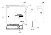
図11は、従来技術によるコンピュータ装置(ここでは、パーソナルコンピュータとし、以下、パソコンと略称する)の代表的な利用形態の一例を概略的に示す。パソコン本体104に、ディスプレイモニタ装置100接続されると共に、入力デバイスとしてキーボード105およびマウス106が接続される。パソコン本体104は、CPU(Central Processing Unit) 、ハードディスクドライブ、メモリ、バスシステムおよび入出力インターフェイスなどを有し(図示しない)、所定のプログラムに基づき動作する。
【0004】
モニタ装置100は、例えばCRT(Cathode Ray Tube)やLCD(Liquid Crystal Display)を表示デバイスとして用いる。モニタ装置100は、前面に、上述の表示デバイスによる表示がなされる表示部101および操作スイッチ103を有する。パソコン本体104からモニタ装置100に対して、映像信号107が供給される。モニタ100では、供給された映像信号107の周波数や解像度に従い、表示部101に所定の画面表示を行う。
【0005】
表示部101には、さらに、上述したキーボード105やマウス106に対する操作に応じて表示位置が移動されるカーソル108が表示される。例えば、マウス106の操作によるマウス移動量がパソコン本体104に供給される。パソコン本体104では、供給されたマウス移動量に基づき画面上でのマウス座標を求めると共に、カーソル108を表示するための映像信号を生成する。カーソル108を表示する映像信号は、マウス座標に基づき上述の映像信号107に重畳され、モニタ装置100に供給される。
【0006】
マウス106と、マウス106の動きに対応して表示が移動されるカーソル108とを用いることで、ユーザは、パソコン本体104の操作を、表示部101の表示を見ながら直感的に行うことができる。そのため、マウス106は、キーボード105と共に、入力用のデバイスとして急速に普及が進んでいる。
【0007】
また、表示部101には、操作スイッチ103の操作に基づき、OSDによるコントロール画面102が表示される。OSD画面102の表示は、後述するように、モニタ装置100内部で生成された表示制御信号に基づきなされ、表示部101の表示の最前面に表示される。
【0008】
図12は、モニタ装置100の一例の構成を示す。このモニタ装置100は、映像信号116および117の2系統の映像信号の入力が可能とされており、入力された映像信号116および117は、ビデオ入力スイッチ112で一方を選択され、ビデオミックス回路113に供給される。例えば、映像信号116がパソコン本体104から供給された信号である。
【0009】
一方、モニタ装置100は、CPU110を有し、操作スイッチ103の操作に対応した制御信号118がCPU110に供給される。制御信号118に基づき、CPU110によりOSD画面102用のキャラクタ発生を指示するコマンドが発行される。このコマンドに基づき、キャラクタジェネレータ111によって、例えばRGB信号からなる所定の映像信号が生成される。キャラクタジェネレータ111の出力は、ビデオミックス回路113に供給される。
【0010】
ビデオミックス回路113では、キャラクタジェネレータ111から供給された映像信号と、上述したビデオ入力スイッチ112で選択された映像信号とを混合し、パソコン本体104から出力された表示に対してOSD画面102の表示が重畳された映像信号を出力する。ビデオミックス回路113から出力された映像信号は、表示制御回路114を介して画像表示デバイス115に供給される。画像表示デバイス115は、上述した表示部101の表示を行うための、例えばCRTやLCDといったデバイスである。
【0011】
なお、表示制御回路114は、操作スイッチ103の操作に基づくCPU110の制御により、供給された映像信号に対して所定の処理を施し、画像表示デバイス115による表示画質、例えばコントラスト、明るさおよび色調などの制御を行う。すなわち、モニタ100において、操作スイッチ103により所定の操作を行うことで、OSD画面102が表示される。図11の例では、OSD画面102は、表示部101のコントラストの設定値が表示されている。操作スイッチ103の所定の操作により、表示部101のコントラストを調整することができ、それに伴い、OSD画面102に示されるコントラストを示す値が変更される。
【0012】
図13は、表示部101に、パソコン104本体による画面に対してOSD画面102が表示された例を示す。この例では、OSD画面102に、コントラスト調整のためのコントロールが表示されている。モニタ装置100上の操作スイッチ103を操作することによって、例えばコントラストの設定値を増減させることができ、それに伴い、OSD画面102の表示も変更される。
【0013】
【発明が解決しようとする課題】
従来では、モニタ装置100側で、キーボード105からのキー情報や、マウス106からのマウス座標情報を取得することができなかった。したがって、OSD表示に基づく操作などを行う際に、キーボード105やマウス106を用いることができなかったという問題点があった。このため、モニタ装置100のコントロールを行うためには、モニタ装置100の前面に設けられた操作スイッチ103を使用せざるをえなく、非常に作業性が悪かったという問題点があった。
【0014】
したがって、この発明の目的は、コンピュータ装置に入力を行う入力デバイスからモニタ装置をコントロールできるようにされた画像表示装置および方法を提供することにある。
【0015】
【課題を解決するための手段】
この発明は、上述の課題を解決するために、
コンピュータ装置から供給された映像信号を表示する画像表示装置において、
コンピュータ装置から供給された映像信号を表示する表示手段と、
入力デバイスの操作に応じた操作情報を受信する受信手段と、
表示手段の表示制御情報の表示を行う表示制御情報表示信号を生成して映像信号と合成する表示制御情報表示手段と、
入力デバイスから操作情報として出力された位置情報に基づき、表示制御情報表示手段により表示された表示制御情報表示にカーソル表示を重畳するカーソル表示手段と、
表示制御情報表示手段による表示を行うかどうかを切り替える切替手段と
を有し、
受信手段によって受信された操作信号に基づき、表示手段の表示の制御を行うようにし、
切替手段により表示制御情報表示手段による表示を行わないように切り替えられたときに、表示制御情報表示手段による表示を行ったときにカーソル表示手段により表示されているカーソル表示の位置に対応する位置に、コンピュータ装置から供給された映像信号によるカーソル表示を行うようにしたことを特徴とする画像表示装置である。
【0016】
この発明は、
コンピュータ装置から供給された映像信号を表示する画像表示方法において、
表示手段の表示制御情報の表示を行う表示制御情報表示信号を生成して、コンピュータから供給される映像信号と合成するステップと、
入力デバイスから操作情報として出力された位置情報に基づき、表示された表示制御情報表示にカーソル表示を重畳するステップと、
表示手段の表示制御情報の表示を行わないように切り替えられた場合、表示手段の表示制御情報の表示を行ったときに表示されているカーソル表示の位置に対応する位置に、コンピュータ装置から供給された映像信号によるカーソル表示を行うようにするステップと
を有することを特徴とする画像表示方法である。
【0017】
上述したように、この発明は、入力デバイスの操作に応じた操作情報を受信し、受信された操作情報に基づき表示制御を行うようにされているため、コンピュータ装置の操作と画像表示装置の表示制御の操作とをシームレスに行うことができる。
【0018】
【発明の実施の形態】
以下、この発明の実施の第1の形態を、図面を参照しながら説明する。図1は、この実施の第1の形態によるコンピュータ装置の使用例を概略的に示す。パソコン本体5に、ディスプレイモニタ装置1が接続される。また、パソコン本体5に、入力デバイスとしてキーボード6およびマウス7が接続される。キーボード6は、操作に応じてキー情報を出力する。また、マウス7は、マウス7が移動されるのに伴いマウス移動量(X,Y)およびボタンの押下に応じたボタン情報を出力する。パソコン本体5は、CPU(Central Processing Unit) 、ハードディスクドライブ、メモリ、バスシステムおよび入出力インターフェイスなどを有し(図示しない)、所定のプログラムに基づき動作する。
【0019】
モニタ装置1は、例えばCRT(Cathode Ray Tube)やLCD(Liquid Crystal Display)を表示デバイスとして用いる。モニタ装置1は、前面に、上述の表示デバイスによる表示がなされる表示部2および操作スイッチ4を有する。表示部2には、パソコン本体5から供給された映像信号8に基づく表示がなされる。また、所定の形状のカーソル10が映像信号8による表示に対して合成されて表示される。カーソル10は、画面上の、例えば上述のマウス移動量に基づき求められた座標位置に表示される。
【0020】
すなわち、マウス7の移動量やボタン押下情報がマウス7からパソコン本体5に供給される。パソコン本体5では、マウス7から供給されたこれらの情報に基づき、カーソル10を表示する映像信号が生成される。生成されたマウス10を表示するための映像信号がアプリケーションソフトウェアなどで生成された映像信号に合成されて、映像信号8とされて、モニタ装置1に供給される。
【0021】
また、表示部2には、操作スイッチ4の操作に基づき、OSDによるコントロールを行うためのOSD画面3が表示される。OSD画面3が表示されることで、モニタ装置1においてOSD機能を実行させることができる。OSD画面3の表示は、後述するように、モニタ装置1内部で生成された映像信号に基づきなされる。
【0022】
この発明では、さらに、キーボード6によるキー情報およびマウス7によるマウス座標情報などの入力操作信号9がパソコン本体5を介してモニタ装置1に供給される。例えば、キーボード6からパソコン本体5に供給されたキー情報は、パソコン本体5で加工されること無く入力操作信号9とされ、モニタ装置1に送信される。また例えば、マウス7からパソコン本体5に供給されたマウス移動量に基づき、カーソル10が表示されている表示部2の、画面左上隅などを基準点とした(X,Y)座標が求められ、ボタン情報と共に入力操作信号9としてモニタ装置1に送信される。
【0023】
モニタ装置1では、供給された映像信号8に基づきなされている表示部2の表示の解像度を認識可能なようにされている。これにより、モニタ装置1において、OSD画面3の表示位置と、パソコン本体5から供給された映像信号8による表示位置との相対関係を認識することができる。
【0024】
入力操作信号9がパソコン本体5からモニタ装置1に送信されるため、上述したOSDによる表示がなされている間、例えばマウス7の操作によってカーソル10をOSD画面3内に移動させることで、OSDにより表示されたコントロールをマウス7で制御することが可能とされる。
【0025】
もちろん、キーボード6を用いてOSDによるコントロールを制御することも可能である。このときには、例えば、キーボード6のキーに所定の機能を割り当て、そのキーが押下されたときに対応するコマンドが発行されるようにする。
【0026】
入力操作信号9をパソコン本体5からモニタ装置1に対して伝送する際のインターフェイスは、パソコン5に標準的に装備されている、RS−232Cを用いることができる。また、これに限らず、USB(Universal Serial Bus)やIEEE1394をインターフェイスとして用いることができる。
【0027】
なお、キー情報やカーソル座標情報は、パソコン本体5側で、例えばパソコン本体5のOS(Operating System)によりこれらの情報を監視して、一定間隔でモニタ装置1に送信するようにもできる。
【0028】
図2は、モニタ装置1の一例の構成を示す。パソコン本体5から出力された映像信号8がビデオミックス回路24に供給される。一方、パソコン本体5から出力された入力操作信号9は、モニタ装置1内のCPU20に供給される。CPU20において、入力操作信号9に基づきカーソル指示信号が生成され、カーソルキャラクタジェネレータ22に供給される。カーソルキャラクタジェネレータ22では、カーソル指示信号に基づき、所定座標にカーソル表示がなされるような、例えばRGB信号からなる所定の映像信号が生成される。
【0029】
一方、モニタ装置1に設けられた操作スイッチ4の操作に対応して生成された制御信号11に基づき、CPU20により、OSD用のキャラクタ発生を指示するキャラクタ発生指示コマンドが発行される。キャラクタ発生指示コマンドは、キャラクタジェネレータ21に供給され、例えばRGB信号からなる所定の映像信号が生成される。キャラクタジェネレータ21の出力は、OSDミックス回路23に供給される。
【0030】
OSDミックス回路23では、キャラクタジェネレータ21およびカーソルキャラクタジェネレータ22からそれぞれ供給された映像信号を合成し、OSD画面3内の表示を行う映像信号を生成する。この映像信号は、ビデオミックス回路24に供給され、上述したパソコン5本体から供給された映像信号8と合成される。ビデオミックス回路24から出力された映像信号は、表示制御回路25に供給される。
【0031】
表示制御回路25は、CPU20の制御に基づき、供給された映像信号に対して所定の処理を施し、画像表示デバイス26による表示の制御がなされる。例えば、コントラスト、明るさおよび色調などの表示画質の制御や、映像信号の画像表示デバイス26への表示位置などの制御が表示制御回路25により行われる。表示制御回路25の出力は、例えばCRTやLCDおよび駆動回路による画像表示デバイス26に供給され、表示部2に対する所定の表示がなされる。
【0032】
なお、映像信号8の解像度情報や周波数情報は、CPU20によって映像信号8から抽出することができる。パソコン本体5から映像信号8と共に、これらの情報が供給されるようにしてもよい。
【0033】
図3は、OSD画面3の一例の表示を示す。この図3の例では、OSD画面3に、画像表示デバイス26に対するコントラスト調整を行うコントロール画面が表示されている。例えばモニタ装置1の操作スイッチ4を押すことで、OSD画面3の表示が行われる。コントラストの設定値がバー表示33として表示される。OSD画面3内に、カーソルキャラクタジェネレータ22のカーソル指示信号に基づき、カーソル30が表示される。
【0034】
カーソル30は、パソコン本体5に接続された、例えばマウス7の動きに応じてOSD画面3内を移動される。パソコン本体5から供給されたマウス7の座標情報が、モニタ装置1のCPU20によりOSD画面3内の(X,Y)座標に変換され、カーソルキャラクタジェネレータ22により、変換された座標位置にカーソル表示を行うような映像信号が生成される。この映像信号がOSDミックス回路23に供給され、キャラクタジェネレータ21により生成されたOSDの表示を行う映像信号に重畳される。
【0035】
領域31、32および34は、入力有効領域である。マウス7の座標情報に基づきカーソル30がこれらの領域内に存在するかどうかが判断される。例えば、カーソル30の表示の所定の点の座標がカーソル30の位置を代表する座標とされる。カーソル30がこれら入力有効領域31、32あるいは34内にあるときに、例えばマウス7に対して所定のボタン操作が行われると、領域31、32および34のうちボタン操作が行われたときにカーソル30が存在する領域に応じた入力がなされる。
【0036】
この例では、領域31にカーソル30が存在するときにマウス7のボタン操作を行うと、CPU20から表示制御回路25に対して、コントラスト設定値が減少されるような制御信号が供給され、画面のコントラストを減少させるように制御がなされる。それと共に、バー表示33がコントラスト設定値の変更に応じて更新される。同様に、領域32にカーソル30が存在するときにマウス7のボタン操作を行うと、コントラスト設定値が増加されるように制御され、それに応じてバー表示33が更新される。領域34内にカーソル30が存在するときにマウス7のボタン操作を行うと、OSD表示を解除することができる。
【0037】
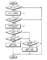
次に、図4のフローチャートを用いて、上述したマウス7を用いたモニタ装置1の制御について説明する。なお、この図4に示されるフローチャートは、OSD機能が有効とされた後には、全体がループとされて処理され、一連の処理が終了されると、再び処理が最初のステップに戻される。すなわち、所定の間隔でこのフロー処理がなされ、マウス7の座標情報やボタン操作などが監視される。
【0038】
図4のフローチャートの実行に先んじて、例えばモニタ装置1に設けられた操作スイッチ4が操作され、OSD画面3が表示される。そして、パソコン本体5から送られた、カーソル座標を送信する送信コマンドがモニタ装置1に認識されると、フローが開始される。最初のステップS10で、OSD画面3が表示され、OSD機能が有効とされているかどうかが判断される。若し、OSD機能が有効とされていると判断されたら、処理はステップS11に移行する。一方、OSD機能が有効とされていないと判断されれば、一連の処理が終了される。
【0039】
なお、モニタ装置1において、パソコン本体から供給された映像信号8の解像度は、予め分かっているものとする。
【0040】
ステップS11では、パソコン本体5から供給された入力操作信号9に基づき、カーソルの座標情報を取得する。そして、次のステップS12において、取得されたカーソルの座標情報に示される位置が、表示部2に表示されているOSD画面3の領域内であるかどうかが判断される。若し、カーソルの座標情報に示される位置がOSD画面3の領域内であると判断されれば、処理はステップS13に移行する。一方、カーソルがOSD画面3の領域内に無いと判断されれば、一連の処理が終了される。
【0041】
ステップS13では、入力操作信号9に基づき取得されたカーソル10の座標情報に基づき、OSD画面3内の対応位置にOSD用のカーソル30が表示される。すなわち、CPU20によりマウスの座標情報に基づくコマンドが生成され、生成されたコマンドがカーソルキャラクタジェネレータ22に対して送られる。
【0042】
上述したように、OSD画面3を表示するためのコマンドと、カーソル30を表示させるためのコマンドとは、それぞれ独立してCPU20からキャラクタジェネレータ21およびカーソルキャラクタジェネレータ22に送られる。したがって、カーソル30の表示とOSD画面3の表示とは、互いに独立して発生される。キャラクタジェネレータ21およびカーソルキャラクタジェネレータ22でそれぞれ発生されたOSD画面3を表示させる映像信号と、カーソル30を表示させる映像信号とは、OSDミックス回路24に供給され、OSD画面3に対してカーソル3が重畳された映像信号が生成される。
【0043】
次のステップS14で、マウス7に対するボタン操作が行われたかどうかが判断される。若し、マウス7に対してボタン操作が行われたと判断されたら、処理はステップS15に移行し、ボタン操作されたときのカーソル30の表示位置が、上述した入力有効領域31、32あるいは34内にあるかどうかが判断される。若し、何れかの有効領域内にあったと判断されたら、ステップS16で、上述したような、カーソル30のある領域に対応した処理がなされる。
【0044】
一方、上述のステップS14でマウス7に対するボタン操作がされていないと判断されるか、あるいは、ステップS15でマウス7に対するボタン操作された位置が入力有効領域31、32あるいは34の何れでもないとされたら、処理はステップS17に移行する。
【0045】
ステップS17では、入力操作信号9によるマウスの座標情報に基づき、マウスが移動されたかどうかが判断される。若し、マウスの座標情報が変化していて、マウスが移動されたと判断されたら、処理はステップS18に移行する。ステップS18では、CPU20からカーソルキャラクタジェネレータ22に対して、OSD画面3内に表示されているカーソル30を移動させる旨のコマンドが発行される。
【0046】
一例として、前回のフローの処理終了時のマウス座標が(X0,Y0)であるとして、今回のフローにおいて、マウスの座標がこの座標(X0,Y0)に対して移動しているかどうかを認識する。今回のフローの座標情報が(X,Y)となっており、前回のフロー時の座標(X0,Y0)と比較して変化している場合には、CPU20からキャラクタジェネレータ23に対して、変化の差分の(X−X0,Y−Y0)だけカーソル30の表示位置を変更させるコマンドを発行する。
【0047】
一方、ステップS17で、マウスが移動していないと判断されたら、一連の処理が終了される。
【0048】
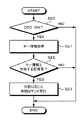
上述では、OSD画面3に対する操作を、マウス7を用いて行う例について説明したが、これはこの例に限らず、キーボード6を用いてOSD画面3に対する操作を行うようにもできる。図5は、キーボード6を用いてOSD画面3に対する処理を行う際の一例のフローチャートを示す。キーボード6を用いる場合には、例えば、上述の領域31、32および34に対応する機能がキーボード6の所定のキーにそれぞれ割り当てられる。
【0049】
なお、この図5のフローチャートも、上述の図4のフローチャートと同様に、OSD機能が有効とされた後には、全体がループとされて処理され、一連の処理が終了されると、再び処理が最初のステップに戻される。また、図5のフローチャートの実行に先んじて、例えばモニタ装置1に設けられた操作スイッチ4が操作され、OSD画面3が表示される。
【0050】
パソコン本体5から送られた、キー情報を送信する送信コマンドがモニタ装置1に認識されると、フローが開始される。最初のステップS20で、OSD機能が有効とされているかどうか判断される。若し、有効とされていると判断されれば、処理は次のステップS21に移行する。一方、OSD機能が有効とされていないと判断されれば、一連の処理が終了される。
【0051】
ステップS21では、パソコン本体5からモニタ装置1に供給される入力操作信号9に基づき、キー情報を取得する。次のステップS22で、現在表示されているOSD画面3において、取得されたキー情報と合致する処理が存在するかどうかが判断される。若し、取得されたキー情報と合致する処理が存在すると判断されたら、処理はステップS23に移行する。取得されたキー情報と合致する処理が存在しないと判断された場合には、一連の処理が終了される。
【0052】
ステップS23では、キー情報に対応してOSD画面3を更新する制御コマンドが発行され、発行された制御コマンドがキャラクタジェネレータ22に供給される。それと共に、キー情報に対応したOSD機能を実現させる制御コマンドが発行され、発行された制御コマンドが表示制御回路25に供給される。
【0053】
次に、この発明の実施の第2の形態について、図面を参照しながら説明する。図6は、実施の第2の形態によるコンピュータ装置の使用例を概略的に示す。図6および後述の図7において、上述の図1および図2と共通する部分については同一の番号を付し、詳細な説明を省略する。この実施の第2の形態では、モニタ装置40に対して、キーボード6およびマウス7のインターフェイスが設けられると共に、キーボード6およびマウス7から出力されたキー情報、マウス座標情報およびボタン操作情報は、モニタ装置1に供給され、それぞれキーボード6から出力された入力操作信号41Aおよびマウス7から出力された41Bとして、モニタ装置40からパソコン本体5に送信される。
【0054】
図7は、実施の第2の形態によるモニタ装置40の一例の構成を示す。キーボード6から出力されるキー情報、マウス7から出力されるマウス移動量およびボタン操作情報がCPU20に供給される。また、モニタ装置1に設けられた操作スイッチ4による制御信号11がCPU20に供給される。
【0055】
CPU20から、供給されたキー情報に基づく入力操作信号41Aが出力される。また、CPU20から、供給されたマウス座標情報およびボタン情報に基づく入力操作信号41Bが出力される。例えば、入力操作信号41Aおよび41Bは、それぞれ、本来キーボード6およびマウス7から出力される本来の信号と同一の信号としてCPU20から出力される。入力操作信号41Aおよび41Bは、パソコン本体5に標準的に設けられるキーボード入力端子およびマウス入力端子(図示しない)にそれぞれ供給される。
【0056】
これに限らず、CPU20で、供給されたキー情報、マウス座標情報およびボタン操作情報を所定に加工して、他のインターフェイスを介してパソコン本体5に対して供給するようにしてもよい。適用可能なインターフェイスとしては、例えば、RS−232C、USB、IEEE1394など、パソコン本体5に標準的に設けられる様々なインターフェイスを用いることができる。
【0057】
CPU20では、上述のように、供給されたキー情報、マウス座標情報およびボタン操作情報に基づき入力操作信号41Aおよび41Bを出力すると共に、供給されたこれらの信号に基づき、OSD画面3を表示するためのコマンドと、カーソル30を表示させるためのコマンドとを発行する。これらのコマンドは、キャラクタジェネレータ21およびカーソルキャラクタジェネレータ22にそれぞれ供給される。
【0058】
また、CPU20では、OSD機能が有効とされている場合には、供給されたキー情報、マウス座標情報およびボタン操作情報に基づき、表示制御回路25に対する制御信号を生成する。生成された制御信号は、表示制御回路25に供給される。
【0059】
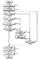
次に、図8のフローチャートを用いて、この実施の第2の形態による、マウス7を用いたモニタ装置40の制御について説明する。この図8に示されるフローチャートは、OSD機能が有効とされた後には、全体がループとされて処理され、一連の処理が終了されると、再び処理が最初のステップに戻される。すなわち、所定の間隔でこのフロー処理がなされ、マウス7の移動量やボタン操作などが監視される。
【0060】
モニタ装置1に設けられた操作スイッチ4が操作され、OSD機能が有効とされたら、ステップS20により、パソコン本体5に対するマウス7の出力信号の送信が停止される。その後、モニタ装置1において、OSD画面3の表示と、OSD画面3内へのカーソル30の表示がなされるように制御される(ステップS21)。
【0061】
次のステップS22では、CPU20において、マウス7から出力された信号を受信したかどうかが判断される。若し、受信したとされれば、処理はステップS23に移行する。一方、受信していないと判断されれば、処理は後述するステップS30に移行する。ステップS23では、マウス7のボタン操作が行われたかどうかが判断され、若し、マウス7のボタン操作がなされていないと判断されれば、処理は後述するステップS28に移行する。一方、マウス7のボタンが押され、ボタン操作が行われたと判断されれば、処理は次のステップS24に移行する。
【0062】
ステップS23でマウス7においてボタン操作が行われたとされれば、ステップS24で、そのボタン操作が行われたときのマウス7の座標が求められ、ボタン操作がOSD画面3内の入力が有効な位置で行われたかどうかが判断される。例えば、上述の図3の例では、入力有効領域31、32あるいは34の範囲内にカーソル30があるときに、マウス7に対するボタン操作が行われれば、有効な位置でのボタン操作であると判断される。若し、有効な位置でボタン操作がなされてないと判断されれば、処理は後述するステップS28に移行する。
【0063】
一方、入力有効領域内でボタン操作が行われたと判断されれば、ステップS25に移行する。ステップS25では、上述のステップS23でボタン操作が行われた座標が、OSD機能を解除するための入力有効領域34であるかどうかが判断される。若し、ボタン操作が行われた位置が入力有効領域34でないと判断されれば、処理は後述するステップS28に移行する。一方、ボタン操作が行われた座標が入力有効領域34であると判断されれば、処理はステップS26に移行する。
【0064】
ステップS26では、表示部2内の、OSD画面3によるカーソル30が表示されている位置と同一の位置に、パソコン本体5の制御によるカーソルが表示されるように指示するコマンドが、CPU20からパソコン本体5に対して送信される。コマンドが送信されると、処理はステップS27に移行し、CPU20において、キャラクタジェネレータ21およびカーソルキャラクタジェネレータ22に対して、OSD画面3の表示をOFFにするコマンドがそれぞれ発行される。
【0065】
これらのステップS26およびS27により、OSD画面3による制御からパソコン本体5による制御への移行を、シームレスに行うことができる。
【0066】
上述したステップS28以降の処理について説明する。ステップS28では、マウス7が移動されたかどうかが判断される。若し、マウスの座標情報が前回のフローと変化しておらず、マウス7が移動されていないと判断されたら、処理は後述するステップS30に移行する。
【0067】
一方、マウスの座標情報が変化していて、マウスが移動されたと判断されたら、処理はステップS29に移行する。ステップS29では、CPU20からカーソルキャラクタジェネレータ22に対して、OSD画面3内に表示されているカーソル30を移動させる旨のコマンドが発行される。コマンドが発行されたら、処理はステップS30に移行する。
【0068】
ステップS30では、モニタ装置1の操作スイッチ4のON/OFF状態が判断される。若し、操作スイッチ4がON状態とされ、OSD機能が有効とされていれば、処理はステップS22に戻される。一方、操作スイッチ4がOFFとされており、OSD機能が解除されていれば、処理は上述したステップS26の移行し、OSD画面3のカーソル30が表示されていた位置と同一の位置に、パソコン本体5によるカーソルがなされるように、CPU20からパソコン本体5に対して、コマンドが発行される。
【0069】
なお、上述では、実施の第2の形態においてマウス7によってOSD画面3の制御を行うように説明されているが、これはこの例に限定されず、上述した実施の第1の形態と同様にして、キーボード6からOSD画面3の制御を行うようにもできる。
【0070】
この実施の第2の形態によれば、モニタ装置1にマウス7およびキーボード6が直接的に接続され、OSD画面3におけるカーソル30は、モニタ装置1の内部処理で行われる。また、パソコン本体5には、モニタ装置1から、通常のマウス7およびキーボード6の入力と同様な入力がなされる。そのため、パソコン本体5に、モニタ制御用のソフトウェアを別途にインストールする必要がない。
【0071】
次に、この発明の実施の第3の形態について、図面を参照しながら説明する。図9は、実施の第3の形態によるコンピュータ装置の使用例を概略的に示す。図9および後述の図10において、上述の図1および図2、ならびに、図6および図7と共通する部分については同一の番号を付し、詳細な説明を省略する。
【0072】
この実施の第3の形態では、上述の実施の第2の形態と同様に、モニタ装置50にキーボード6およびマウス7のインターフェイスが設けられる。さらに、この実施の第3の形態では、モニタ装置50に対して2台のパソコン本体5および5’が接続できるようにされている。モニタ装置50の表示部2は、パソコン本体5および5’から供給される映像信号8および8’にそれぞれ対応した表示部2Aおよび2Bに分割される。
【0073】
上述した実施の第2の形態と同様に、キーボード6のキー情報、ならびに、マウス7の移動量およびボタン操作情報は、モニタ装置50を介してパソコン本体5および5’に送信される。パソコン本体5へは、キー情報およびマウスからの情報がそれぞれ入力操作信号42Aおよび42Bとして供給される。同様に、パソコン本体5’へは、キー情報およびマウスからの情報がそれぞれ入力操作信号42’Aおよび42’Bとして供給される。
【0074】
図10は、実施の第3の形態によるモニタ装置50の一例の構成を示す。パソコン本体5および5’からそれぞれ供給された映像信号8および8’は、ビデオメモリインターフェイス45に供給され、ビデオメモリ46に一旦格納される。例えば、映像信号8および8’は、ビデオメモリインターフェイス45のアドレス制御に基づき、ビデオメモリ46上に設けられた対応する領域にそれぞれ格納される。
【0075】
図示は省略するが、ビデオメモリインターフェイス45および後述するビデオスイッチ47は、CPU20に制御される。ビデオメモリ46に格納された映像信号8および8’は、CPU20の制御に基づき、ビデオメモリインターフェイス45によりビデオメモリ46から所定に読み出される。ビデオメモリ46から読み出された映像信号8および8’は、CPU20の制御に基づきビデオスイッチ47により選択されてビデオミックス回路24に供給される。
【0076】
映像信号8および8’を、それぞれ、一旦ビデオメモリ46に格納し、これを読み出して画像表示デバイス26に供給するようにしているため、映像信号8および8’の周波数を変換することができる。これにより、同一画面に複数のパソコン本体5および5’の画像を表示することが可能とされる。また、モニタ装置50に接続された複数台のコンピュータ装置の表示画面およびOSD画面3間でのカーソルの移動を、シームレスに行うことができる。
【0077】
一方、OSD画面3の表示およびOSD画面3におけるカーソル30の表示は、上述の実施の第1および第2の形態と同様にしてなされる。すなわち、CPU20で発行されたコマンドに基づきキャラクタジェネレータ21およびカーソルキャラクタジェネレータ22によって、OSD画面3およびカーソル30を表示するための映像信号がそれぞれ生成され、OSDミックス回路23で生成されたこれらの映像信号が合成される。
【0078】
合成された映像信号は、ビデオミックス回路24に供給され、上述した、ビデオメモリ46から読み出されビデオスイッチ47で選択された映像信号と、OSD画面3の映像信号とが合成され、表示制御回路25でCPU20の制御に基づき画質の調整などがなされ、画像表示デバイス26に供給される。
【0079】
なお、2台のパソコン本体5および5’の使い分けは、例えば、パソコン本体5および5’のうち、現在使用している装置を優先して、選択的にキー情報およびマウス情報を送信することができる。また、パソコン本体5および5’によるカーソルの座標に基づき、映像信号8および8’の表示領域が接する境界にカーソルが移動したら、パソコン本体5および5’を切り替えるようにしてもよい。
【0080】
このように、モニタ装置50が2台のパソコン本体5および5’を接続可能な構成とされていても、図8のフローチャートを用いて上述した制御を行うことが可能である。また、モニタ装置50は、2台のみならず、さらに多数のコンピュータ装置を接続するように構成することができる。
【0081】
なお、上述ではコンピュータ装置に対して用いられる入力デバイスがマウスおよびキーボードであるとして説明したが、これはこの例に限定されない。例えば、ペン上の入力補助器具や指先などで、(X,Y)平面上で入力を行うようにされたタブレットや、ボールを回転させることで(X,Y)平面上での座標を指定することができるトラックボールなどを入力デバイスとして用いることができる。
【0082】
【発明の効果】
以上説明したように、この発明は、モニタ装置がカーソル座標などを認識可能なように構成されているため、モニタ装置の制御に、コンピュータ装置に対する入力デバイスであるキーボードやマウスを用いることができる効果がある。
【0083】
またそれにより、コンピュータ装置の制御からモニタ装置の制御への移行をシームレスに行えるようになる効果がある。
【0084】
さらに、この発明の実施の第2および第3の形態によれば、モニタ装置にキーボードやマウスといった入力デバイスが直接的に接続され、モニタ装置からコンピュータ装置に対してキーボードやマウスからの信号が供給されるようになっている。そのため、モニタ装置を制御するためのソフトウェアをコンピュータ装置にインストールする必要が無いという効果がある。
【0085】
さらにまた、この発明の実施の第3の形態によれば、それぞれ1台のモニタ装置、キーボードおよびマウスを、複数台のコンピュータ装置で共有することができるため、複数台のコンピュータを設置するような場合の設置スペースを節約することができるという効果がある。
【図面の簡単な説明】
【図1】実施の第1の形態によるコンピュータ装置の使用例を概略的に示す略線図である。
【図2】実施の第1の形態によるモニタ装置の一例の構成を示すブロック図である。
【図3】OSD画面の一例の表示を示す略線図である。
【図4】実施の第1の形態による、マウスを用いてモニタ装置を制御する一例のフローチャートである。
【図5】キーボードを用いてOSD画面に対する処理を行う際の一例のフローチャートである。
【図6】実施の第2の形態によるコンピュータ装置の使用例を概略的に示す略線図である。
【図7】実施の第2の形態によるモニタ装置の一例の構成を示すブロック図である。
【図8】実施の第2の形態による、マウスを用いてモニタ装置を制御する一例のフローチャートである。
【図9】実施の第3の形態によるコンピュータ装置の使用例を概略的に示す略線図である。
【図10】実施の第3の形態によるモニタ装置の一例の構成を示すブロック図である。
【図11】従来技術によるコンピュータ装置の代表的な利用形態の一例を概略的に示す略線図である。
【図12】従来技術によるモニタ装置の一例の構成を示すブロック図である。
【図13】表示部にパソコン本体による画面に対してOSD画面が表示された例を示す略線図である。
【符号の説明】
1,40,50・・・モニタ装置、2・・・表示部、3・・・OSD画面、4・・・操作スイッチ、5・・・パソコン本体、6・・・キーボード、7・・・マウス、8・・・映像信号、9・・・入力操作信号、10・・・カーソル、20・・・CPU、21・・・キャラクタジェネレータ、22・・・カーソルキャラクタジェネレータ、23・・・OSDミックス回路、24・・・ビデオミックス回路、25・・・表示制御回路、26・・・画像表示デバイス、30・・・カーソル、31,32,34・・・入力有効領域[0001]
BACKGROUND OF THE INVENTION
The present invention relates to an image display apparatus and method that can be suitably used as a monitor of a computer apparatus and can control the monitor from an input device that operates the computer apparatus.
[0002]
[Prior art]
In recent years, a monitor device connected to a computer device such as a personal computer or a workstation is generally configured to control display screen characteristics and the like by an OSD (On Screen Display) function. . That is, using an operating means such as a switch provided on the monitor device, the OSDFurther, a predetermined display (referred to as OSD screen) is performed on the screen. The OSD screen is a display generated internally in the monitor device. In accordance with the OSD screen, the user operates a switch or the like provided on the monitor device to adjust the screen contrast, brightness, color tone, and the like.
[0003]
FIG. 11 schematically shows an example of a typical use form of a computer device according to the prior art (herein, a personal computer, hereinafter abbreviated as a personal computer). A
[0004]
The
[0005]
The
[0006]
By using the
[0007]
The
[0008]
FIG. 12 shows an exemplary configuration of the
[0009]
On the other hand, the
[0010]
The
[0011]
The
[0012]
FIG. 13 shows an example in which the
[0013]
[Problems to be solved by the invention]
Conventionally, on the
[0014]
SUMMARY OF THE INVENTION Accordingly, an object of the present invention is to provide an image display apparatus and method capable of controlling a monitor apparatus from an input device for inputting to a computer apparatus.
[0015]
[Means for Solving the Problems]
In order to solve the above-described problems, the present invention
In an image display device for displaying a video signal supplied from a computer device,
Display means for displaying a video signal supplied from a computer device;
Receiving means for receiving operation information corresponding to the operation of the input device;,
Display control information display means for generating a display control information display signal for displaying the display control information of the display means and combining it with the video signal;
Cursor display means for superimposing a cursor display on the display control information display displayed by the display control information display means based on the position information output as operation information from the input device;
Switching means for switching whether to perform display by the display control information display means;
Have
Based on the operation signal received by the receiving means, the display of the display means is controlled.And
When switching is performed so that display by the display control information display unit is not performed by the switching unit, the position corresponding to the position of the cursor display displayed by the cursor display unit when the display by the display control information display unit is performed Cursor display by video signal supplied from computer deviceThe image display device is characterized.
[0016]
This invention
In an image display method for displaying a video signal supplied from a computer device,
Generating a display control information display signal for displaying the display control information of the display means and combining it with a video signal supplied from a computer;
Superimposing a cursor display on the displayed display control information display based on position information output as operation information from the input device;
When switching is made so that the display control information of the display means is not displayed, it is supplied from the computer device to a position corresponding to the position of the cursor display displayed when the display control information of the display means is displayed. Step to display the cursor by the video signal
HaveAn image display method characterized by this.
[0017]
As described above, the present invention receives the operation information corresponding to the operation of the input device, and performs display control based on the received operation information. Therefore, the operation of the computer device and the display of the image display device are performed. Control operations can be performed seamlessly.
[0018]
DETAILED DESCRIPTION OF THE INVENTION
A first embodiment of the present invention will be described below with reference to the drawings. FIG. 1 schematically shows an example of use of the computer apparatus according to the first embodiment. The display monitor device 1 is connected to the personal computer
[0019]
The monitor device 1 uses, for example, a CRT (Cathode Ray Tube) or an LCD (Liquid Crystal Display) as a display device. The monitor device 1 has a
[0020]
That is, the amount of movement of the mouse 7 and button press information are supplied from the mouse 7 to the personal computer
[0021]
The
[0022]
In the present invention, input operation signals 9 such as key information from the keyboard 6 and mouse coordinate information from the mouse 7 are supplied to the monitor device 1 via the personal computer
[0023]
In the monitor device 1, the display resolution of the
[0024]
Since the input operation signal 9 is transmitted from the personal computer
[0025]
Of course, it is also possible to control the control by the OSD using the keyboard 6. At this time, for example, a predetermined function is assigned to a key of the keyboard 6 so that a corresponding command is issued when the key is pressed.
[0026]
As an interface for transmitting the input operation signal 9 from the personal computer
[0027]
Note that the key information and the cursor coordinate information can be transmitted to the monitor device 1 at regular intervals by monitoring the information on the personal computer
[0028]
FIG. 2 shows an exemplary configuration of the monitor device 1. The
[0029]
On the other hand, based on the
[0030]
The
[0031]
Based on the control of the
[0032]
Note that the resolution information and frequency information of the
[0033]
FIG. 3 shows an example display of the
[0034]
The
[0035]
[0036]
In this example, the cursor is in area 313When the mouse 7 is operated when 0 exists, a control signal for reducing the contrast setting value is supplied from the
[0037]
Next, control of the monitor device 1 using the mouse 7 will be described with reference to the flowchart of FIG. In the flowchart shown in FIG. 4, after the OSD function is validated, the entire process is processed as a loop, and when a series of processes is completed, the process returns to the first step. That is, the flow process is performed at a predetermined interval, and the coordinate information of the mouse 7 and the button operation are monitored.
[0038]
Prior to the execution of the flowchart of FIG. 4, for example, the
[0039]
In the monitor apparatus 1, it is assumed that the resolution of the
[0040]
In step S11, the coordinate information of the cursor is acquired based on the input operation signal 9 supplied from the personal computer
[0041]
In step S <b> 13, the
[0042]
As described above, the command for displaying the
[0043]
In the next step S14, it is determined whether or not a button operation on the mouse 7 has been performed. If it is determined that the button operation has been performed on the mouse 7, the process proceeds to step S15, and the display position of the
[0044]
On the other hand, it is determined that the button operation on the mouse 7 is not performed in step S14 described above, or the position where the button operation is performed on the mouse 7 in step S15 is not any of the input
[0045]
In step S17, it is determined whether or not the mouse has been moved based on the coordinate information of the mouse based on the input operation signal 9. If it is determined that the coordinate information of the mouse has changed and the mouse has been moved, the process proceeds to step S18. In step S18, the
[0046]
As an example, assuming that the mouse coordinates at the end of the process of the previous flow are (X0, Y0), in the current flow, it is recognized whether or not the mouse coordinates have moved relative to the coordinates (X0, Y0). . When the coordinate information of the current flow is (X, Y) and changes compared to the coordinates (X0, Y0) at the previous flow, the
[0047]
On the other hand, if it is determined in step S17 that the mouse has not moved, the series of processing ends.
[0048]
In the above description, the example in which the operation on the
[0049]
Note that the flowchart of FIG. 5 is also processed in a loop after the OSD function is enabled, as in the flowchart of FIG. 4 described above. Return to the first step. Prior to the execution of the flowchart of FIG. 5, for example, the
[0050]
When the monitor device 1 recognizes a transmission command transmitted from the personal computer
[0051]
In step S21, key information is acquired based on the input operation signal 9 supplied from the personal computer
[0052]
In step S23, a control command for updating the
[0053]
Next, a second embodiment of the present invention will be described with reference to the drawings. FIG. 6 schematically shows an example of use of a computer apparatus according to the second embodiment. In FIG. 6 and FIG. 7 described later, the same reference numerals are given to the portions common to the above-described FIG. 1 and FIG. 2, and detailed description thereof will be omitted. In the second embodiment, an interface of a keyboard 6 and a mouse 7 is provided for the
[0054]
FIG. 7 shows an example of the configuration of the
[0055]
An
[0056]
However, the present invention is not limited to this, and the supplied key information, mouse coordinate information, and button operation information may be processed in a predetermined manner by the
[0057]
As described above, the
[0058]
In addition, when the OSD function is enabled, the
[0059]
Next, control of the
[0060]
When the
[0061]
In the next step S22, the
[0062]
If a button operation is performed on the mouse 7 in step S23, the coordinates of the mouse 7 when the button operation is performed are obtained in step S24, and the button operation is a position where the input in the
[0063]
On the other hand, if it is determined that the button operation has been performed within the input valid area, the process proceeds to step S25. In step S25, it is determined whether or not the coordinate where the button operation is performed in step S23 described above is the input
[0064]
In step S26, a command for instructing that the cursor controlled by the personal computer
[0065]
By these steps S26 and S27, the transition from the control by the
[0066]
The process after step S28 mentioned above is demonstrated. In step S28, it is determined whether or not the mouse 7 has been moved. If it is determined that the coordinate information of the mouse has not changed from the previous flow and the mouse 7 has not been moved, the process proceeds to step S30 described later.
[0067]
On the other hand, if the coordinate information of the mouse has changed and it is determined that the mouse has been moved, the process proceeds to step S29. In step S29, the
[0068]
In step S30, the ON / OFF state of the
[0069]
In the above description, the
[0070]
According to the second embodiment, the mouse 7 and the keyboard 6 are directly connected to the monitor device 1, and the
[0071]
Next, a third embodiment of the present invention will be described with reference to the drawings. FIG. 9 schematically shows an example of use of a computer apparatus according to the third embodiment. In FIG. 9 and FIG. 10 described later, parts common to those in FIGS. 1 and 2 and FIGS. 6 and 7 are given the same reference numerals, and detailed description thereof is omitted.
[0072]
In the third embodiment, as in the second embodiment described above, the
[0073]
Similar to the second embodiment described above, the key information of the keyboard 6 and the movement amount and button operation information of the mouse 7 are transmitted to the
[0074]
FIG. 10 shows an example of the configuration of the
[0075]
Although not shown, the
[0076]
Since the video signals 8 and 8 'are once stored in the
[0077]
On the other hand, display of
[0078]
The synthesized video signal is supplied to the
[0079]
Note that the two PC
[0080]
Thus, even if the
[0081]
In the above description, the input devices used for the computer apparatus are described as a mouse and a keyboard. However, this is not limited to this example. For example, the coordinates on the (X, Y) plane are specified by rotating a tablet or a ball that is input on the (X, Y) plane with an input assist device or a fingertip on the pen. A trackball or the like that can be used as an input device.
[0082]
【The invention's effect】
As described above, the present invention is configured such that the monitor device can recognize the cursor coordinates and the like, so that the keyboard and mouse, which are input devices for the computer device, can be used to control the monitor device. There is.
[0083]
This also has the effect of allowing seamless transition from computer device control to monitor device control.
[0084]
Furthermore, according to the second and third embodiments of the present invention, input devices such as a keyboard and a mouse are directly connected to the monitor device, and signals from the keyboard and mouse are supplied from the monitor device to the computer device. It has come to be. Therefore, there is an effect that it is not necessary to install software for controlling the monitor device in the computer device.
[0085]
Furthermore, according to the third embodiment of the present invention, each monitor device, keyboard and mouse can be shared by a plurality of computer devices, so that a plurality of computers are installed. In this case, the installation space can be saved.
[Brief description of the drawings]
FIG. 1 is a schematic diagram schematically illustrating an example of use of a computer device according to a first embodiment;
FIG. 2 is a block diagram showing a configuration of an example of a monitor device according to the first embodiment.
FIG. 3 is a schematic diagram illustrating a display example of an OSD screen.
FIG. 4 is a flowchart of an example of controlling a monitor device using a mouse according to the first embodiment;
FIG. 5 is a flowchart illustrating an example of processing performed on an OSD screen using a keyboard.
FIG. 6 is a schematic diagram schematically illustrating a usage example of a computer device according to a second embodiment;
FIG. 7 is a block diagram showing a configuration of an example of a monitor device according to a second embodiment.
FIG. 8 is a flowchart of an example of controlling a monitor device using a mouse according to the second embodiment.
FIG. 9 is a schematic diagram schematically illustrating an example of use of a computer device according to a third embodiment;
FIG. 10 is a block diagram showing a configuration of an example of a monitor device according to a third embodiment.
FIG. 11 is a schematic diagram schematically illustrating an example of a typical usage pattern of a computer device according to the related art.
FIG. 12 is a block diagram showing a configuration of an example of a monitor device according to the prior art.
FIG. 13 is a schematic diagram illustrating an example in which an OSD screen is displayed on the display unit with respect to the screen of the personal computer main body.
[Explanation of symbols]
DESCRIPTION OF
Claims (5)
コンピュータ装置から供給された映像信号を表示する表示手段と、
入力デバイスの操作に応じた操作情報を受信する受信手段と、
上記表示手段の表示制御情報の表示を行う表示制御情報表示信号を生成して上記映像信号と合成する表示制御情報表示手段と、
上記入力デバイスから上記操作情報として出力された位置情報に基づき、上記表示制御情報表示手段により表示された上記表示制御情報表示にカーソル表示を重畳するカーソル表示手段と、
上記表示制御情報表示手段による上記表示を行うかどうかを切り替える切替手段と
を有し、
上記受信手段によって受信された上記操作信号に基づき、上記表示手段の表示の制御を行うようにし、
上記切替手段により上記表示制御情報表示手段による表示を行わないように切り替えられたときに、上記表示制御情報表示手段による上記表示を行ったときに上記カーソル表示手段により表示されているカーソル表示の位置に対応する位置に、上記コンピュータ装置から供給された上記映像信号による上記カーソル表示を行うようにしたことを特徴とする画像表示装置。In an image display device for displaying a video signal supplied from a computer device,
Display means for displaying a video signal supplied from a computer device;
Receiving means for receiving operation information according to the operation of the input device ;
Display control information display means for generating a display control information display signal for displaying the display control information of the display means and combining it with the video signal;
Cursor display means for superimposing a cursor display on the display control information display displayed by the display control information display means based on the position information output as the operation information from the input device;
Switching means for switching whether to perform the display by the display control information display means ,
Based on the operation signal received by the receiving means, control the display of the display means ,
The position of the cursor display displayed by the cursor display means when the display is performed by the display control information display means when the switching means is switched so as not to perform the display by the display control information display means. An image display device characterized in that the cursor display by the video signal supplied from the computer device is performed at a position corresponding to .
上記入力デバイスは上記コンピュータ装置に接続され、上記操作情報は、上記コンピュータ装置を介して上記受信手段により受信されることを特徴とする画像表示装置。The image display device according to claim 1,
The image display apparatus, wherein the input device is connected to the computer apparatus, and the operation information is received by the receiving means via the computer apparatus.
上記受信手段は、上記入力デバイスから直接的に上記操作情報を受信し、受信された上記操作情報は、上記コンピュータ装置にも送信されることを特徴とする画像表示装置。The image display device according to claim 1,
The image display apparatus, wherein the reception unit receives the operation information directly from the input device, and the received operation information is also transmitted to the computer apparatus.
上記表示制御情報表示に、1または複数の入力有効領域が設けられ、上記入力有効領域に上記カーソル表示があるときに、上記入力デバイスに対する所定の操作が行われたことを示す上記操作情報を受信したら、上記表示手段の表示を上記所定の操作に応じて制御することを特徴とする画像表示装置。The image display device according to claim 1 ,
When the display control information display is provided with one or more input effective areas, and the cursor is displayed in the input effective area, the operation information indicating that a predetermined operation is performed on the input device is received. Then, the display of the said display means is controlled according to the said predetermined operation, The image display apparatus characterized by the above-mentioned.
表示手段の表示制御情報の表示を行う表示制御情報表示信号を生成して、コンピュータから供給される映像信号と合成するステップと、
入力デバイスから操作情報として出力された位置情報に基づき、表示された表示制御情報表示にカーソル表示を重畳するステップと、
表示手段の表示制御情報の表示を行わないように切り替えられた場合、表示手段の表示制御情報の表示を行ったときに表示されているカーソル表示の位置に対応する位置に、コンピュータ装置から供給された映像信号によるカーソル表示を行うようにするステップと
を有することを特徴とする画像表示方法。In an image display method for displaying a video signal supplied from a computer device,
Generating a display control information display signal for displaying the display control information of the display means and combining it with a video signal supplied from a computer;
Superimposing a cursor display on the displayed display control information display based on position information output as operation information from the input device;
When switching is made so that the display control information of the display means is not displayed, it is supplied from the computer device to a position corresponding to the position of the cursor display displayed when the display control information of the display means is displayed. Step to display the cursor by the video signal
An image display method characterized by comprising:
Priority Applications (1)
| Application Number | Priority Date | Filing Date | Title |
|---|---|---|---|
| JP35603699A JP4200616B2 (en) | 1999-12-15 | 1999-12-15 | Image display apparatus and method |
Applications Claiming Priority (1)
| Application Number | Priority Date | Filing Date | Title |
|---|---|---|---|
| JP35603699A JP4200616B2 (en) | 1999-12-15 | 1999-12-15 | Image display apparatus and method |
Publications (3)
| Publication Number | Publication Date |
|---|---|
| JP2001175378A JP2001175378A (en) | 2001-06-29 |
| JP2001175378A5 JP2001175378A5 (en) | 2006-05-11 |
| JP4200616B2 true JP4200616B2 (en) | 2008-12-24 |
Family
ID=18447009
Family Applications (1)
| Application Number | Title | Priority Date | Filing Date |
|---|---|---|---|
| JP35603699A Expired - Fee Related JP4200616B2 (en) | 1999-12-15 | 1999-12-15 | Image display apparatus and method |
Country Status (1)
| Country | Link |
|---|---|
| JP (1) | JP4200616B2 (en) |
Families Citing this family (4)
| Publication number | Priority date | Publication date | Assignee | Title |
|---|---|---|---|---|
| KR20030094853A (en) * | 2002-06-08 | 2003-12-18 | 삼성전자주식회사 | Apparatus and method for controlling the display unit |
| JP5511023B2 (en) * | 2009-06-12 | 2014-06-04 | Necディスプレイソリューションズ株式会社 | Video display system and method |
| JP5617375B2 (en) | 2010-06-22 | 2014-11-05 | ソニー株式会社 | Image display device, display control method, and program |
| CN114089843A (en) * | 2020-08-04 | 2022-02-25 | 瑞昱半导体股份有限公司 | Display equipment with screen function display picture control mechanism and screen function display picture control method thereof |
-
1999
- 1999-12-15 JP JP35603699A patent/JP4200616B2/en not_active Expired - Fee Related
Also Published As
| Publication number | Publication date |
|---|---|
| JP2001175378A (en) | 2001-06-29 |
Similar Documents
| Publication | Publication Date | Title |
|---|---|---|
| US6538675B2 (en) | Display control apparatus and display control system for switching control of two position indication marks | |
| KR100762038B1 (en) | Image displaying apparatus and method | |
| US5612715A (en) | System and method for dynamically adjusting display resolution of computer generated displays | |
| US20050235221A1 (en) | Computer, display device setting method, and program | |
| US20080250350A1 (en) | Switch and On-Screen Display Systems and Methods | |
| KR20120135799A (en) | Display apparatus, control method and image processing apparatus thereof | |
| US20120287042A1 (en) | Portable terminal and display output method thereof | |
| EP2869587A1 (en) | Multimedia device and remote control device for synchronizing screen, and method for same | |
| TWI493532B (en) | Display controlling device and display controlling method | |
| US20030227490A1 (en) | Control apparatus and method of display device | |
| JP2007249476A (en) | Information processing device and information processing method | |
| JP4200616B2 (en) | Image display apparatus and method | |
| JPH11305917A (en) | Image display system | |
| CN104111809A (en) | Display control unit and display control method | |
| CN104285199B (en) | Cursor movement control method, computer program, cursor movement control device, and image display system | |
| KR101727317B1 (en) | Display apparatus and control method thereof | |
| JP2005091751A (en) | Image display control method, image display device, display controller, computer and image display control system | |
| JP4921642B2 (en) | Information processing apparatus and display control method | |
| US20210232295A1 (en) | Control method for displayed picture and display system thereof | |
| JP6716519B2 (en) | Display device and display method | |
| EP1961218B1 (en) | Display apparatus and method and information processing apparatus and method for providing picture in picture function | |
| JP2004151488A (en) | Display unit, display device and picture display system | |
| JP3585101B2 (en) | Display device | |
| JP3550234B2 (en) | Data converter | |
| JP3575355B2 (en) | RGB signal input switching device and power consumption reduction method |
Legal Events
| Date | Code | Title | Description |
|---|---|---|---|
| A521 | Request for written amendment filed |
Free format text: JAPANESE INTERMEDIATE CODE: A523 Effective date: 20060314 |
|
| A621 | Written request for application examination |
Free format text: JAPANESE INTERMEDIATE CODE: A621 Effective date: 20060314 |
|
| A977 | Report on retrieval |
Free format text: JAPANESE INTERMEDIATE CODE: A971007 Effective date: 20080605 |
|
| A131 | Notification of reasons for refusal |
Free format text: JAPANESE INTERMEDIATE CODE: A131 Effective date: 20080610 |
|
| A521 | Request for written amendment filed |
Free format text: JAPANESE INTERMEDIATE CODE: A523 Effective date: 20080811 |
|
| TRDD | Decision of grant or rejection written | ||
| A01 | Written decision to grant a patent or to grant a registration (utility model) |
Free format text: JAPANESE INTERMEDIATE CODE: A01 Effective date: 20080916 |
|
| A01 | Written decision to grant a patent or to grant a registration (utility model) |
Free format text: JAPANESE INTERMEDIATE CODE: A01 |
|
| A61 | First payment of annual fees (during grant procedure) |
Free format text: JAPANESE INTERMEDIATE CODE: A61 Effective date: 20080929 |
|
| FPAY | Renewal fee payment (event date is renewal date of database) |
Free format text: PAYMENT UNTIL: 20111017 Year of fee payment: 3 |
|
| FPAY | Renewal fee payment (event date is renewal date of database) |
Free format text: PAYMENT UNTIL: 20121017 Year of fee payment: 4 |
|
| LAPS | Cancellation because of no payment of annual fees |