JP4197094B2 - Self-broaching, rotary push-in implant for interbody fusion - Google Patents
Self-broaching, rotary push-in implant for interbody fusion Download PDFInfo
- Publication number
- JP4197094B2 JP4197094B2 JP2000579154A JP2000579154A JP4197094B2 JP 4197094 B2 JP4197094 B2 JP 4197094B2 JP 2000579154 A JP2000579154 A JP 2000579154A JP 2000579154 A JP2000579154 A JP 2000579154A JP 4197094 B2 JP4197094 B2 JP 4197094B2
- Authority
- JP
- Japan
- Prior art keywords
- implant
- adjacent vertebral
- vertebral body
- height dimension
- lower walls
- Prior art date
- Legal status (The legal status is an assumption and is not a legal conclusion. Google has not performed a legal analysis and makes no representation as to the accuracy of the status listed.)
- Expired - Fee Related
Links
Images


Classifications
-
- A—HUMAN NECESSITIES
- A61—MEDICAL OR VETERINARY SCIENCE; HYGIENE
- A61F—FILTERS IMPLANTABLE INTO BLOOD VESSELS; PROSTHESES; DEVICES PROVIDING PATENCY TO, OR PREVENTING COLLAPSING OF, TUBULAR STRUCTURES OF THE BODY, e.g. STENTS; ORTHOPAEDIC, NURSING OR CONTRACEPTIVE DEVICES; FOMENTATION; TREATMENT OR PROTECTION OF EYES OR EARS; BANDAGES, DRESSINGS OR ABSORBENT PADS; FIRST-AID KITS
- A61F2/00—Filters implantable into blood vessels; Prostheses, i.e. artificial substitutes or replacements for parts of the body; Appliances for connecting them with the body; Devices providing patency to, or preventing collapsing of, tubular structures of the body, e.g. stents
- A61F2/02—Prostheses implantable into the body
- A61F2/30—Joints
- A61F2/44—Joints for the spine, e.g. vertebrae, spinal discs
- A61F2/4455—Joints for the spine, e.g. vertebrae, spinal discs for the fusion of spinal bodies, e.g. intervertebral fusion of adjacent spinal bodies, e.g. fusion cages
- A61F2/446—Joints for the spine, e.g. vertebrae, spinal discs for the fusion of spinal bodies, e.g. intervertebral fusion of adjacent spinal bodies, e.g. fusion cages having a circular or elliptical cross-section substantially parallel to the axis of the spine, e.g. cylinders or frustocones
-
- A—HUMAN NECESSITIES
- A61—MEDICAL OR VETERINARY SCIENCE; HYGIENE
- A61F—FILTERS IMPLANTABLE INTO BLOOD VESSELS; PROSTHESES; DEVICES PROVIDING PATENCY TO, OR PREVENTING COLLAPSING OF, TUBULAR STRUCTURES OF THE BODY, e.g. STENTS; ORTHOPAEDIC, NURSING OR CONTRACEPTIVE DEVICES; FOMENTATION; TREATMENT OR PROTECTION OF EYES OR EARS; BANDAGES, DRESSINGS OR ABSORBENT PADS; FIRST-AID KITS
- A61F2/00—Filters implantable into blood vessels; Prostheses, i.e. artificial substitutes or replacements for parts of the body; Appliances for connecting them with the body; Devices providing patency to, or preventing collapsing of, tubular structures of the body, e.g. stents
- A61F2/02—Prostheses implantable into the body
- A61F2/30—Joints
- A61F2/44—Joints for the spine, e.g. vertebrae, spinal discs
- A61F2/4455—Joints for the spine, e.g. vertebrae, spinal discs for the fusion of spinal bodies, e.g. intervertebral fusion of adjacent spinal bodies, e.g. fusion cages
- A61F2/447—Joints for the spine, e.g. vertebrae, spinal discs for the fusion of spinal bodies, e.g. intervertebral fusion of adjacent spinal bodies, e.g. fusion cages substantially parallelepipedal, e.g. having a rectangular or trapezoidal cross-section
-
- A—HUMAN NECESSITIES
- A61—MEDICAL OR VETERINARY SCIENCE; HYGIENE
- A61F—FILTERS IMPLANTABLE INTO BLOOD VESSELS; PROSTHESES; DEVICES PROVIDING PATENCY TO, OR PREVENTING COLLAPSING OF, TUBULAR STRUCTURES OF THE BODY, e.g. STENTS; ORTHOPAEDIC, NURSING OR CONTRACEPTIVE DEVICES; FOMENTATION; TREATMENT OR PROTECTION OF EYES OR EARS; BANDAGES, DRESSINGS OR ABSORBENT PADS; FIRST-AID KITS
- A61F2/00—Filters implantable into blood vessels; Prostheses, i.e. artificial substitutes or replacements for parts of the body; Appliances for connecting them with the body; Devices providing patency to, or preventing collapsing of, tubular structures of the body, e.g. stents
- A61F2/02—Prostheses implantable into the body
- A61F2/28—Bones
-
- A—HUMAN NECESSITIES
- A61—MEDICAL OR VETERINARY SCIENCE; HYGIENE
- A61F—FILTERS IMPLANTABLE INTO BLOOD VESSELS; PROSTHESES; DEVICES PROVIDING PATENCY TO, OR PREVENTING COLLAPSING OF, TUBULAR STRUCTURES OF THE BODY, e.g. STENTS; ORTHOPAEDIC, NURSING OR CONTRACEPTIVE DEVICES; FOMENTATION; TREATMENT OR PROTECTION OF EYES OR EARS; BANDAGES, DRESSINGS OR ABSORBENT PADS; FIRST-AID KITS
- A61F2/00—Filters implantable into blood vessels; Prostheses, i.e. artificial substitutes or replacements for parts of the body; Appliances for connecting them with the body; Devices providing patency to, or preventing collapsing of, tubular structures of the body, e.g. stents
- A61F2/02—Prostheses implantable into the body
- A61F2/30—Joints
- A61F2/30721—Accessories
- A61F2/30744—End caps, e.g. for closing an endoprosthetic cavity
-
- A—HUMAN NECESSITIES
- A61—MEDICAL OR VETERINARY SCIENCE; HYGIENE
- A61F—FILTERS IMPLANTABLE INTO BLOOD VESSELS; PROSTHESES; DEVICES PROVIDING PATENCY TO, OR PREVENTING COLLAPSING OF, TUBULAR STRUCTURES OF THE BODY, e.g. STENTS; ORTHOPAEDIC, NURSING OR CONTRACEPTIVE DEVICES; FOMENTATION; TREATMENT OR PROTECTION OF EYES OR EARS; BANDAGES, DRESSINGS OR ABSORBENT PADS; FIRST-AID KITS
- A61F2/00—Filters implantable into blood vessels; Prostheses, i.e. artificial substitutes or replacements for parts of the body; Appliances for connecting them with the body; Devices providing patency to, or preventing collapsing of, tubular structures of the body, e.g. stents
- A61F2/02—Prostheses implantable into the body
- A61F2/30—Joints
- A61F2/44—Joints for the spine, e.g. vertebrae, spinal discs
- A61F2/442—Intervertebral or spinal discs, e.g. resilient
-
- A—HUMAN NECESSITIES
- A61—MEDICAL OR VETERINARY SCIENCE; HYGIENE
- A61F—FILTERS IMPLANTABLE INTO BLOOD VESSELS; PROSTHESES; DEVICES PROVIDING PATENCY TO, OR PREVENTING COLLAPSING OF, TUBULAR STRUCTURES OF THE BODY, e.g. STENTS; ORTHOPAEDIC, NURSING OR CONTRACEPTIVE DEVICES; FOMENTATION; TREATMENT OR PROTECTION OF EYES OR EARS; BANDAGES, DRESSINGS OR ABSORBENT PADS; FIRST-AID KITS
- A61F2/00—Filters implantable into blood vessels; Prostheses, i.e. artificial substitutes or replacements for parts of the body; Appliances for connecting them with the body; Devices providing patency to, or preventing collapsing of, tubular structures of the body, e.g. stents
- A61F2/02—Prostheses implantable into the body
- A61F2/30—Joints
- A61F2/46—Special tools or methods for implanting or extracting artificial joints, accessories, bone grafts or substitutes, or particular adaptations therefor
- A61F2/4603—Special tools or methods for implanting or extracting artificial joints, accessories, bone grafts or substitutes, or particular adaptations therefor for insertion or extraction of endoprosthetic joints or of accessories thereof
- A61F2/4611—Special tools or methods for implanting or extracting artificial joints, accessories, bone grafts or substitutes, or particular adaptations therefor for insertion or extraction of endoprosthetic joints or of accessories thereof of spinal prostheses
-
- A—HUMAN NECESSITIES
- A61—MEDICAL OR VETERINARY SCIENCE; HYGIENE
- A61F—FILTERS IMPLANTABLE INTO BLOOD VESSELS; PROSTHESES; DEVICES PROVIDING PATENCY TO, OR PREVENTING COLLAPSING OF, TUBULAR STRUCTURES OF THE BODY, e.g. STENTS; ORTHOPAEDIC, NURSING OR CONTRACEPTIVE DEVICES; FOMENTATION; TREATMENT OR PROTECTION OF EYES OR EARS; BANDAGES, DRESSINGS OR ABSORBENT PADS; FIRST-AID KITS
- A61F2/00—Filters implantable into blood vessels; Prostheses, i.e. artificial substitutes or replacements for parts of the body; Appliances for connecting them with the body; Devices providing patency to, or preventing collapsing of, tubular structures of the body, e.g. stents
- A61F2/02—Prostheses implantable into the body
- A61F2/28—Bones
- A61F2002/2817—Bone stimulation by chemical reactions or by osteogenic or biological products for enhancing ossification, e.g. by bone morphogenetic or morphogenic proteins [BMP] or by transforming growth factors [TGF]
-
- A—HUMAN NECESSITIES
- A61—MEDICAL OR VETERINARY SCIENCE; HYGIENE
- A61F—FILTERS IMPLANTABLE INTO BLOOD VESSELS; PROSTHESES; DEVICES PROVIDING PATENCY TO, OR PREVENTING COLLAPSING OF, TUBULAR STRUCTURES OF THE BODY, e.g. STENTS; ORTHOPAEDIC, NURSING OR CONTRACEPTIVE DEVICES; FOMENTATION; TREATMENT OR PROTECTION OF EYES OR EARS; BANDAGES, DRESSINGS OR ABSORBENT PADS; FIRST-AID KITS
- A61F2/00—Filters implantable into blood vessels; Prostheses, i.e. artificial substitutes or replacements for parts of the body; Appliances for connecting them with the body; Devices providing patency to, or preventing collapsing of, tubular structures of the body, e.g. stents
- A61F2/02—Prostheses implantable into the body
- A61F2/28—Bones
- A61F2002/2835—Bone graft implants for filling a bony defect or an endoprosthesis cavity, e.g. by synthetic material or biological material
- A61F2002/2839—Bone plugs or bone graft dowels
-
- A—HUMAN NECESSITIES
- A61—MEDICAL OR VETERINARY SCIENCE; HYGIENE
- A61F—FILTERS IMPLANTABLE INTO BLOOD VESSELS; PROSTHESES; DEVICES PROVIDING PATENCY TO, OR PREVENTING COLLAPSING OF, TUBULAR STRUCTURES OF THE BODY, e.g. STENTS; ORTHOPAEDIC, NURSING OR CONTRACEPTIVE DEVICES; FOMENTATION; TREATMENT OR PROTECTION OF EYES OR EARS; BANDAGES, DRESSINGS OR ABSORBENT PADS; FIRST-AID KITS
- A61F2/00—Filters implantable into blood vessels; Prostheses, i.e. artificial substitutes or replacements for parts of the body; Appliances for connecting them with the body; Devices providing patency to, or preventing collapsing of, tubular structures of the body, e.g. stents
- A61F2/02—Prostheses implantable into the body
- A61F2/30—Joints
- A61F2002/30001—Additional features of subject-matter classified in A61F2/28, A61F2/30 and subgroups thereof
- A61F2002/30003—Material related properties of the prosthesis or of a coating on the prosthesis
- A61F2002/3006—Properties of materials and coating materials
- A61F2002/30062—(bio)absorbable, biodegradable, bioerodable, (bio)resorbable, resorptive
-
- A—HUMAN NECESSITIES
- A61—MEDICAL OR VETERINARY SCIENCE; HYGIENE
- A61F—FILTERS IMPLANTABLE INTO BLOOD VESSELS; PROSTHESES; DEVICES PROVIDING PATENCY TO, OR PREVENTING COLLAPSING OF, TUBULAR STRUCTURES OF THE BODY, e.g. STENTS; ORTHOPAEDIC, NURSING OR CONTRACEPTIVE DEVICES; FOMENTATION; TREATMENT OR PROTECTION OF EYES OR EARS; BANDAGES, DRESSINGS OR ABSORBENT PADS; FIRST-AID KITS
- A61F2/00—Filters implantable into blood vessels; Prostheses, i.e. artificial substitutes or replacements for parts of the body; Appliances for connecting them with the body; Devices providing patency to, or preventing collapsing of, tubular structures of the body, e.g. stents
- A61F2/02—Prostheses implantable into the body
- A61F2/30—Joints
- A61F2002/30001—Additional features of subject-matter classified in A61F2/28, A61F2/30 and subgroups thereof
- A61F2002/30108—Shapes
- A61F2002/3011—Cross-sections or two-dimensional shapes
- A61F2002/30112—Rounded shapes, e.g. with rounded corners
- A61F2002/30113—Rounded shapes, e.g. with rounded corners circular
-
- A—HUMAN NECESSITIES
- A61—MEDICAL OR VETERINARY SCIENCE; HYGIENE
- A61F—FILTERS IMPLANTABLE INTO BLOOD VESSELS; PROSTHESES; DEVICES PROVIDING PATENCY TO, OR PREVENTING COLLAPSING OF, TUBULAR STRUCTURES OF THE BODY, e.g. STENTS; ORTHOPAEDIC, NURSING OR CONTRACEPTIVE DEVICES; FOMENTATION; TREATMENT OR PROTECTION OF EYES OR EARS; BANDAGES, DRESSINGS OR ABSORBENT PADS; FIRST-AID KITS
- A61F2/00—Filters implantable into blood vessels; Prostheses, i.e. artificial substitutes or replacements for parts of the body; Appliances for connecting them with the body; Devices providing patency to, or preventing collapsing of, tubular structures of the body, e.g. stents
- A61F2/02—Prostheses implantable into the body
- A61F2/30—Joints
- A61F2002/30001—Additional features of subject-matter classified in A61F2/28, A61F2/30 and subgroups thereof
- A61F2002/30108—Shapes
- A61F2002/3011—Cross-sections or two-dimensional shapes
- A61F2002/30138—Convex polygonal shapes
- A61F2002/30143—Convex polygonal shapes hexagonal
-
- A—HUMAN NECESSITIES
- A61—MEDICAL OR VETERINARY SCIENCE; HYGIENE
- A61F—FILTERS IMPLANTABLE INTO BLOOD VESSELS; PROSTHESES; DEVICES PROVIDING PATENCY TO, OR PREVENTING COLLAPSING OF, TUBULAR STRUCTURES OF THE BODY, e.g. STENTS; ORTHOPAEDIC, NURSING OR CONTRACEPTIVE DEVICES; FOMENTATION; TREATMENT OR PROTECTION OF EYES OR EARS; BANDAGES, DRESSINGS OR ABSORBENT PADS; FIRST-AID KITS
- A61F2/00—Filters implantable into blood vessels; Prostheses, i.e. artificial substitutes or replacements for parts of the body; Appliances for connecting them with the body; Devices providing patency to, or preventing collapsing of, tubular structures of the body, e.g. stents
- A61F2/02—Prostheses implantable into the body
- A61F2/30—Joints
- A61F2002/30001—Additional features of subject-matter classified in A61F2/28, A61F2/30 and subgroups thereof
- A61F2002/30108—Shapes
- A61F2002/3011—Cross-sections or two-dimensional shapes
- A61F2002/30138—Convex polygonal shapes
- A61F2002/30151—Convex polygonal shapes rhomboidal or parallelogram-shaped
-
- A—HUMAN NECESSITIES
- A61—MEDICAL OR VETERINARY SCIENCE; HYGIENE
- A61F—FILTERS IMPLANTABLE INTO BLOOD VESSELS; PROSTHESES; DEVICES PROVIDING PATENCY TO, OR PREVENTING COLLAPSING OF, TUBULAR STRUCTURES OF THE BODY, e.g. STENTS; ORTHOPAEDIC, NURSING OR CONTRACEPTIVE DEVICES; FOMENTATION; TREATMENT OR PROTECTION OF EYES OR EARS; BANDAGES, DRESSINGS OR ABSORBENT PADS; FIRST-AID KITS
- A61F2/00—Filters implantable into blood vessels; Prostheses, i.e. artificial substitutes or replacements for parts of the body; Appliances for connecting them with the body; Devices providing patency to, or preventing collapsing of, tubular structures of the body, e.g. stents
- A61F2/02—Prostheses implantable into the body
- A61F2/30—Joints
- A61F2002/30001—Additional features of subject-matter classified in A61F2/28, A61F2/30 and subgroups thereof
- A61F2002/30108—Shapes
- A61F2002/3011—Cross-sections or two-dimensional shapes
- A61F2002/30138—Convex polygonal shapes
- A61F2002/30153—Convex polygonal shapes rectangular
-
- A—HUMAN NECESSITIES
- A61—MEDICAL OR VETERINARY SCIENCE; HYGIENE
- A61F—FILTERS IMPLANTABLE INTO BLOOD VESSELS; PROSTHESES; DEVICES PROVIDING PATENCY TO, OR PREVENTING COLLAPSING OF, TUBULAR STRUCTURES OF THE BODY, e.g. STENTS; ORTHOPAEDIC, NURSING OR CONTRACEPTIVE DEVICES; FOMENTATION; TREATMENT OR PROTECTION OF EYES OR EARS; BANDAGES, DRESSINGS OR ABSORBENT PADS; FIRST-AID KITS
- A61F2/00—Filters implantable into blood vessels; Prostheses, i.e. artificial substitutes or replacements for parts of the body; Appliances for connecting them with the body; Devices providing patency to, or preventing collapsing of, tubular structures of the body, e.g. stents
- A61F2/02—Prostheses implantable into the body
- A61F2/30—Joints
- A61F2002/30001—Additional features of subject-matter classified in A61F2/28, A61F2/30 and subgroups thereof
- A61F2002/30108—Shapes
- A61F2002/30199—Three-dimensional shapes
- A61F2002/30205—Three-dimensional shapes conical
- A61F2002/3021—Three-dimensional shapes conical frustoconical
-
- A—HUMAN NECESSITIES
- A61—MEDICAL OR VETERINARY SCIENCE; HYGIENE
- A61F—FILTERS IMPLANTABLE INTO BLOOD VESSELS; PROSTHESES; DEVICES PROVIDING PATENCY TO, OR PREVENTING COLLAPSING OF, TUBULAR STRUCTURES OF THE BODY, e.g. STENTS; ORTHOPAEDIC, NURSING OR CONTRACEPTIVE DEVICES; FOMENTATION; TREATMENT OR PROTECTION OF EYES OR EARS; BANDAGES, DRESSINGS OR ABSORBENT PADS; FIRST-AID KITS
- A61F2/00—Filters implantable into blood vessels; Prostheses, i.e. artificial substitutes or replacements for parts of the body; Appliances for connecting them with the body; Devices providing patency to, or preventing collapsing of, tubular structures of the body, e.g. stents
- A61F2/02—Prostheses implantable into the body
- A61F2/30—Joints
- A61F2002/30001—Additional features of subject-matter classified in A61F2/28, A61F2/30 and subgroups thereof
- A61F2002/30108—Shapes
- A61F2002/30199—Three-dimensional shapes
- A61F2002/30224—Three-dimensional shapes cylindrical
-
- A—HUMAN NECESSITIES
- A61—MEDICAL OR VETERINARY SCIENCE; HYGIENE
- A61F—FILTERS IMPLANTABLE INTO BLOOD VESSELS; PROSTHESES; DEVICES PROVIDING PATENCY TO, OR PREVENTING COLLAPSING OF, TUBULAR STRUCTURES OF THE BODY, e.g. STENTS; ORTHOPAEDIC, NURSING OR CONTRACEPTIVE DEVICES; FOMENTATION; TREATMENT OR PROTECTION OF EYES OR EARS; BANDAGES, DRESSINGS OR ABSORBENT PADS; FIRST-AID KITS
- A61F2/00—Filters implantable into blood vessels; Prostheses, i.e. artificial substitutes or replacements for parts of the body; Appliances for connecting them with the body; Devices providing patency to, or preventing collapsing of, tubular structures of the body, e.g. stents
- A61F2/02—Prostheses implantable into the body
- A61F2/30—Joints
- A61F2002/30001—Additional features of subject-matter classified in A61F2/28, A61F2/30 and subgroups thereof
- A61F2002/30108—Shapes
- A61F2002/30199—Three-dimensional shapes
- A61F2002/30261—Three-dimensional shapes parallelepipedal
-
- A—HUMAN NECESSITIES
- A61—MEDICAL OR VETERINARY SCIENCE; HYGIENE
- A61F—FILTERS IMPLANTABLE INTO BLOOD VESSELS; PROSTHESES; DEVICES PROVIDING PATENCY TO, OR PREVENTING COLLAPSING OF, TUBULAR STRUCTURES OF THE BODY, e.g. STENTS; ORTHOPAEDIC, NURSING OR CONTRACEPTIVE DEVICES; FOMENTATION; TREATMENT OR PROTECTION OF EYES OR EARS; BANDAGES, DRESSINGS OR ABSORBENT PADS; FIRST-AID KITS
- A61F2/00—Filters implantable into blood vessels; Prostheses, i.e. artificial substitutes or replacements for parts of the body; Appliances for connecting them with the body; Devices providing patency to, or preventing collapsing of, tubular structures of the body, e.g. stents
- A61F2/02—Prostheses implantable into the body
- A61F2/30—Joints
- A61F2002/30001—Additional features of subject-matter classified in A61F2/28, A61F2/30 and subgroups thereof
- A61F2002/30316—The prosthesis having different structural features at different locations within the same prosthesis; Connections between prosthetic parts; Special structural features of bone or joint prostheses not otherwise provided for
- A61F2002/30329—Connections or couplings between prosthetic parts, e.g. between modular parts; Connecting elements
- A61F2002/30405—Connections or couplings between prosthetic parts, e.g. between modular parts; Connecting elements made by screwing complementary threads machined on the parts themselves
-
- A—HUMAN NECESSITIES
- A61—MEDICAL OR VETERINARY SCIENCE; HYGIENE
- A61F—FILTERS IMPLANTABLE INTO BLOOD VESSELS; PROSTHESES; DEVICES PROVIDING PATENCY TO, OR PREVENTING COLLAPSING OF, TUBULAR STRUCTURES OF THE BODY, e.g. STENTS; ORTHOPAEDIC, NURSING OR CONTRACEPTIVE DEVICES; FOMENTATION; TREATMENT OR PROTECTION OF EYES OR EARS; BANDAGES, DRESSINGS OR ABSORBENT PADS; FIRST-AID KITS
- A61F2/00—Filters implantable into blood vessels; Prostheses, i.e. artificial substitutes or replacements for parts of the body; Appliances for connecting them with the body; Devices providing patency to, or preventing collapsing of, tubular structures of the body, e.g. stents
- A61F2/02—Prostheses implantable into the body
- A61F2/30—Joints
- A61F2002/30001—Additional features of subject-matter classified in A61F2/28, A61F2/30 and subgroups thereof
- A61F2002/30316—The prosthesis having different structural features at different locations within the same prosthesis; Connections between prosthetic parts; Special structural features of bone or joint prostheses not otherwise provided for
- A61F2002/30329—Connections or couplings between prosthetic parts, e.g. between modular parts; Connecting elements
- A61F2002/30476—Connections or couplings between prosthetic parts, e.g. between modular parts; Connecting elements locked by an additional locking mechanism
- A61F2002/30487—Circumferential cooperating grooves and beads on cooperating lateral surfaces of a mainly longitudinal connection
-
- A—HUMAN NECESSITIES
- A61—MEDICAL OR VETERINARY SCIENCE; HYGIENE
- A61F—FILTERS IMPLANTABLE INTO BLOOD VESSELS; PROSTHESES; DEVICES PROVIDING PATENCY TO, OR PREVENTING COLLAPSING OF, TUBULAR STRUCTURES OF THE BODY, e.g. STENTS; ORTHOPAEDIC, NURSING OR CONTRACEPTIVE DEVICES; FOMENTATION; TREATMENT OR PROTECTION OF EYES OR EARS; BANDAGES, DRESSINGS OR ABSORBENT PADS; FIRST-AID KITS
- A61F2/00—Filters implantable into blood vessels; Prostheses, i.e. artificial substitutes or replacements for parts of the body; Appliances for connecting them with the body; Devices providing patency to, or preventing collapsing of, tubular structures of the body, e.g. stents
- A61F2/02—Prostheses implantable into the body
- A61F2/30—Joints
- A61F2002/30001—Additional features of subject-matter classified in A61F2/28, A61F2/30 and subgroups thereof
- A61F2002/30316—The prosthesis having different structural features at different locations within the same prosthesis; Connections between prosthetic parts; Special structural features of bone or joint prostheses not otherwise provided for
- A61F2002/30329—Connections or couplings between prosthetic parts, e.g. between modular parts; Connecting elements
- A61F2002/30518—Connections or couplings between prosthetic parts, e.g. between modular parts; Connecting elements with possibility of relative movement between the prosthetic parts
- A61F2002/3052—Connections or couplings between prosthetic parts, e.g. between modular parts; Connecting elements with possibility of relative movement between the prosthetic parts unrestrained in only one direction, e.g. moving unidirectionally
-
- A—HUMAN NECESSITIES
- A61—MEDICAL OR VETERINARY SCIENCE; HYGIENE
- A61F—FILTERS IMPLANTABLE INTO BLOOD VESSELS; PROSTHESES; DEVICES PROVIDING PATENCY TO, OR PREVENTING COLLAPSING OF, TUBULAR STRUCTURES OF THE BODY, e.g. STENTS; ORTHOPAEDIC, NURSING OR CONTRACEPTIVE DEVICES; FOMENTATION; TREATMENT OR PROTECTION OF EYES OR EARS; BANDAGES, DRESSINGS OR ABSORBENT PADS; FIRST-AID KITS
- A61F2/00—Filters implantable into blood vessels; Prostheses, i.e. artificial substitutes or replacements for parts of the body; Appliances for connecting them with the body; Devices providing patency to, or preventing collapsing of, tubular structures of the body, e.g. stents
- A61F2/02—Prostheses implantable into the body
- A61F2/30—Joints
- A61F2002/30001—Additional features of subject-matter classified in A61F2/28, A61F2/30 and subgroups thereof
- A61F2002/30316—The prosthesis having different structural features at different locations within the same prosthesis; Connections between prosthetic parts; Special structural features of bone or joint prostheses not otherwise provided for
- A61F2002/30535—Special structural features of bone or joint prostheses not otherwise provided for
- A61F2002/30593—Special structural features of bone or joint prostheses not otherwise provided for hollow
-
- A—HUMAN NECESSITIES
- A61—MEDICAL OR VETERINARY SCIENCE; HYGIENE
- A61F—FILTERS IMPLANTABLE INTO BLOOD VESSELS; PROSTHESES; DEVICES PROVIDING PATENCY TO, OR PREVENTING COLLAPSING OF, TUBULAR STRUCTURES OF THE BODY, e.g. STENTS; ORTHOPAEDIC, NURSING OR CONTRACEPTIVE DEVICES; FOMENTATION; TREATMENT OR PROTECTION OF EYES OR EARS; BANDAGES, DRESSINGS OR ABSORBENT PADS; FIRST-AID KITS
- A61F2/00—Filters implantable into blood vessels; Prostheses, i.e. artificial substitutes or replacements for parts of the body; Appliances for connecting them with the body; Devices providing patency to, or preventing collapsing of, tubular structures of the body, e.g. stents
- A61F2/02—Prostheses implantable into the body
- A61F2/30—Joints
- A61F2002/30001—Additional features of subject-matter classified in A61F2/28, A61F2/30 and subgroups thereof
- A61F2002/30316—The prosthesis having different structural features at different locations within the same prosthesis; Connections between prosthetic parts; Special structural features of bone or joint prostheses not otherwise provided for
- A61F2002/30535—Special structural features of bone or joint prostheses not otherwise provided for
- A61F2002/30604—Special structural features of bone or joint prostheses not otherwise provided for modular
-
- A—HUMAN NECESSITIES
- A61—MEDICAL OR VETERINARY SCIENCE; HYGIENE
- A61F—FILTERS IMPLANTABLE INTO BLOOD VESSELS; PROSTHESES; DEVICES PROVIDING PATENCY TO, OR PREVENTING COLLAPSING OF, TUBULAR STRUCTURES OF THE BODY, e.g. STENTS; ORTHOPAEDIC, NURSING OR CONTRACEPTIVE DEVICES; FOMENTATION; TREATMENT OR PROTECTION OF EYES OR EARS; BANDAGES, DRESSINGS OR ABSORBENT PADS; FIRST-AID KITS
- A61F2/00—Filters implantable into blood vessels; Prostheses, i.e. artificial substitutes or replacements for parts of the body; Appliances for connecting them with the body; Devices providing patency to, or preventing collapsing of, tubular structures of the body, e.g. stents
- A61F2/02—Prostheses implantable into the body
- A61F2/30—Joints
- A61F2/30767—Special external or bone-contacting surface, e.g. coating for improving bone ingrowth
- A61F2/30771—Special external or bone-contacting surface, e.g. coating for improving bone ingrowth applied in original prostheses, e.g. holes or grooves
- A61F2002/30772—Apertures or holes, e.g. of circular cross section
- A61F2002/30774—Apertures or holes, e.g. of circular cross section internally-threaded
-
- A—HUMAN NECESSITIES
- A61—MEDICAL OR VETERINARY SCIENCE; HYGIENE
- A61F—FILTERS IMPLANTABLE INTO BLOOD VESSELS; PROSTHESES; DEVICES PROVIDING PATENCY TO, OR PREVENTING COLLAPSING OF, TUBULAR STRUCTURES OF THE BODY, e.g. STENTS; ORTHOPAEDIC, NURSING OR CONTRACEPTIVE DEVICES; FOMENTATION; TREATMENT OR PROTECTION OF EYES OR EARS; BANDAGES, DRESSINGS OR ABSORBENT PADS; FIRST-AID KITS
- A61F2/00—Filters implantable into blood vessels; Prostheses, i.e. artificial substitutes or replacements for parts of the body; Appliances for connecting them with the body; Devices providing patency to, or preventing collapsing of, tubular structures of the body, e.g. stents
- A61F2/02—Prostheses implantable into the body
- A61F2/30—Joints
- A61F2/30767—Special external or bone-contacting surface, e.g. coating for improving bone ingrowth
- A61F2/30771—Special external or bone-contacting surface, e.g. coating for improving bone ingrowth applied in original prostheses, e.g. holes or grooves
- A61F2002/30772—Apertures or holes, e.g. of circular cross section
- A61F2002/30777—Oblong apertures
-
- A—HUMAN NECESSITIES
- A61—MEDICAL OR VETERINARY SCIENCE; HYGIENE
- A61F—FILTERS IMPLANTABLE INTO BLOOD VESSELS; PROSTHESES; DEVICES PROVIDING PATENCY TO, OR PREVENTING COLLAPSING OF, TUBULAR STRUCTURES OF THE BODY, e.g. STENTS; ORTHOPAEDIC, NURSING OR CONTRACEPTIVE DEVICES; FOMENTATION; TREATMENT OR PROTECTION OF EYES OR EARS; BANDAGES, DRESSINGS OR ABSORBENT PADS; FIRST-AID KITS
- A61F2/00—Filters implantable into blood vessels; Prostheses, i.e. artificial substitutes or replacements for parts of the body; Appliances for connecting them with the body; Devices providing patency to, or preventing collapsing of, tubular structures of the body, e.g. stents
- A61F2/02—Prostheses implantable into the body
- A61F2/30—Joints
- A61F2/30767—Special external or bone-contacting surface, e.g. coating for improving bone ingrowth
- A61F2/30771—Special external or bone-contacting surface, e.g. coating for improving bone ingrowth applied in original prostheses, e.g. holes or grooves
- A61F2002/30772—Apertures or holes, e.g. of circular cross section
- A61F2002/30784—Plurality of holes
- A61F2002/30785—Plurality of holes parallel
-
- A—HUMAN NECESSITIES
- A61—MEDICAL OR VETERINARY SCIENCE; HYGIENE
- A61F—FILTERS IMPLANTABLE INTO BLOOD VESSELS; PROSTHESES; DEVICES PROVIDING PATENCY TO, OR PREVENTING COLLAPSING OF, TUBULAR STRUCTURES OF THE BODY, e.g. STENTS; ORTHOPAEDIC, NURSING OR CONTRACEPTIVE DEVICES; FOMENTATION; TREATMENT OR PROTECTION OF EYES OR EARS; BANDAGES, DRESSINGS OR ABSORBENT PADS; FIRST-AID KITS
- A61F2/00—Filters implantable into blood vessels; Prostheses, i.e. artificial substitutes or replacements for parts of the body; Appliances for connecting them with the body; Devices providing patency to, or preventing collapsing of, tubular structures of the body, e.g. stents
- A61F2/02—Prostheses implantable into the body
- A61F2/30—Joints
- A61F2/30767—Special external or bone-contacting surface, e.g. coating for improving bone ingrowth
- A61F2/30771—Special external or bone-contacting surface, e.g. coating for improving bone ingrowth applied in original prostheses, e.g. holes or grooves
- A61F2002/30772—Apertures or holes, e.g. of circular cross section
- A61F2002/30784—Plurality of holes
- A61F2002/30789—Plurality of holes perpendicular with respect to each other
-
- A—HUMAN NECESSITIES
- A61—MEDICAL OR VETERINARY SCIENCE; HYGIENE
- A61F—FILTERS IMPLANTABLE INTO BLOOD VESSELS; PROSTHESES; DEVICES PROVIDING PATENCY TO, OR PREVENTING COLLAPSING OF, TUBULAR STRUCTURES OF THE BODY, e.g. STENTS; ORTHOPAEDIC, NURSING OR CONTRACEPTIVE DEVICES; FOMENTATION; TREATMENT OR PROTECTION OF EYES OR EARS; BANDAGES, DRESSINGS OR ABSORBENT PADS; FIRST-AID KITS
- A61F2/00—Filters implantable into blood vessels; Prostheses, i.e. artificial substitutes or replacements for parts of the body; Appliances for connecting them with the body; Devices providing patency to, or preventing collapsing of, tubular structures of the body, e.g. stents
- A61F2/02—Prostheses implantable into the body
- A61F2/30—Joints
- A61F2/30767—Special external or bone-contacting surface, e.g. coating for improving bone ingrowth
- A61F2/30771—Special external or bone-contacting surface, e.g. coating for improving bone ingrowth applied in original prostheses, e.g. holes or grooves
- A61F2002/30795—Blind bores, e.g. of circular cross-section
- A61F2002/30805—Recesses of comparatively large area with respect to their low depth
-
- A—HUMAN NECESSITIES
- A61—MEDICAL OR VETERINARY SCIENCE; HYGIENE
- A61F—FILTERS IMPLANTABLE INTO BLOOD VESSELS; PROSTHESES; DEVICES PROVIDING PATENCY TO, OR PREVENTING COLLAPSING OF, TUBULAR STRUCTURES OF THE BODY, e.g. STENTS; ORTHOPAEDIC, NURSING OR CONTRACEPTIVE DEVICES; FOMENTATION; TREATMENT OR PROTECTION OF EYES OR EARS; BANDAGES, DRESSINGS OR ABSORBENT PADS; FIRST-AID KITS
- A61F2/00—Filters implantable into blood vessels; Prostheses, i.e. artificial substitutes or replacements for parts of the body; Appliances for connecting them with the body; Devices providing patency to, or preventing collapsing of, tubular structures of the body, e.g. stents
- A61F2/02—Prostheses implantable into the body
- A61F2/30—Joints
- A61F2/30767—Special external or bone-contacting surface, e.g. coating for improving bone ingrowth
- A61F2/30771—Special external or bone-contacting surface, e.g. coating for improving bone ingrowth applied in original prostheses, e.g. holes or grooves
- A61F2002/3082—Grooves
- A61F2002/30827—Plurality of grooves
-
- A—HUMAN NECESSITIES
- A61—MEDICAL OR VETERINARY SCIENCE; HYGIENE
- A61F—FILTERS IMPLANTABLE INTO BLOOD VESSELS; PROSTHESES; DEVICES PROVIDING PATENCY TO, OR PREVENTING COLLAPSING OF, TUBULAR STRUCTURES OF THE BODY, e.g. STENTS; ORTHOPAEDIC, NURSING OR CONTRACEPTIVE DEVICES; FOMENTATION; TREATMENT OR PROTECTION OF EYES OR EARS; BANDAGES, DRESSINGS OR ABSORBENT PADS; FIRST-AID KITS
- A61F2/00—Filters implantable into blood vessels; Prostheses, i.e. artificial substitutes or replacements for parts of the body; Appliances for connecting them with the body; Devices providing patency to, or preventing collapsing of, tubular structures of the body, e.g. stents
- A61F2/02—Prostheses implantable into the body
- A61F2/30—Joints
- A61F2/30767—Special external or bone-contacting surface, e.g. coating for improving bone ingrowth
- A61F2/30771—Special external or bone-contacting surface, e.g. coating for improving bone ingrowth applied in original prostheses, e.g. holes or grooves
- A61F2002/30841—Sharp anchoring protrusions for impaction into the bone, e.g. sharp pins, spikes
- A61F2002/30845—Sharp anchoring protrusions for impaction into the bone, e.g. sharp pins, spikes with cutting edges
-
- A—HUMAN NECESSITIES
- A61—MEDICAL OR VETERINARY SCIENCE; HYGIENE
- A61F—FILTERS IMPLANTABLE INTO BLOOD VESSELS; PROSTHESES; DEVICES PROVIDING PATENCY TO, OR PREVENTING COLLAPSING OF, TUBULAR STRUCTURES OF THE BODY, e.g. STENTS; ORTHOPAEDIC, NURSING OR CONTRACEPTIVE DEVICES; FOMENTATION; TREATMENT OR PROTECTION OF EYES OR EARS; BANDAGES, DRESSINGS OR ABSORBENT PADS; FIRST-AID KITS
- A61F2/00—Filters implantable into blood vessels; Prostheses, i.e. artificial substitutes or replacements for parts of the body; Appliances for connecting them with the body; Devices providing patency to, or preventing collapsing of, tubular structures of the body, e.g. stents
- A61F2/02—Prostheses implantable into the body
- A61F2/30—Joints
- A61F2/30767—Special external or bone-contacting surface, e.g. coating for improving bone ingrowth
- A61F2/30771—Special external or bone-contacting surface, e.g. coating for improving bone ingrowth applied in original prostheses, e.g. holes or grooves
- A61F2002/30878—Special external or bone-contacting surface, e.g. coating for improving bone ingrowth applied in original prostheses, e.g. holes or grooves with non-sharp protrusions, for instance contacting the bone for anchoring, e.g. keels, pegs, pins, posts, shanks, stems, struts
- A61F2002/30884—Fins or wings, e.g. longitudinal wings for preventing rotation within the bone cavity
-
- A—HUMAN NECESSITIES
- A61—MEDICAL OR VETERINARY SCIENCE; HYGIENE
- A61F—FILTERS IMPLANTABLE INTO BLOOD VESSELS; PROSTHESES; DEVICES PROVIDING PATENCY TO, OR PREVENTING COLLAPSING OF, TUBULAR STRUCTURES OF THE BODY, e.g. STENTS; ORTHOPAEDIC, NURSING OR CONTRACEPTIVE DEVICES; FOMENTATION; TREATMENT OR PROTECTION OF EYES OR EARS; BANDAGES, DRESSINGS OR ABSORBENT PADS; FIRST-AID KITS
- A61F2/00—Filters implantable into blood vessels; Prostheses, i.e. artificial substitutes or replacements for parts of the body; Appliances for connecting them with the body; Devices providing patency to, or preventing collapsing of, tubular structures of the body, e.g. stents
- A61F2/02—Prostheses implantable into the body
- A61F2/30—Joints
- A61F2/30767—Special external or bone-contacting surface, e.g. coating for improving bone ingrowth
- A61F2/30771—Special external or bone-contacting surface, e.g. coating for improving bone ingrowth applied in original prostheses, e.g. holes or grooves
- A61F2002/30878—Special external or bone-contacting surface, e.g. coating for improving bone ingrowth applied in original prostheses, e.g. holes or grooves with non-sharp protrusions, for instance contacting the bone for anchoring, e.g. keels, pegs, pins, posts, shanks, stems, struts
- A61F2002/30891—Plurality of protrusions
- A61F2002/30892—Plurality of protrusions parallel
-
- A—HUMAN NECESSITIES
- A61—MEDICAL OR VETERINARY SCIENCE; HYGIENE
- A61F—FILTERS IMPLANTABLE INTO BLOOD VESSELS; PROSTHESES; DEVICES PROVIDING PATENCY TO, OR PREVENTING COLLAPSING OF, TUBULAR STRUCTURES OF THE BODY, e.g. STENTS; ORTHOPAEDIC, NURSING OR CONTRACEPTIVE DEVICES; FOMENTATION; TREATMENT OR PROTECTION OF EYES OR EARS; BANDAGES, DRESSINGS OR ABSORBENT PADS; FIRST-AID KITS
- A61F2/00—Filters implantable into blood vessels; Prostheses, i.e. artificial substitutes or replacements for parts of the body; Appliances for connecting them with the body; Devices providing patency to, or preventing collapsing of, tubular structures of the body, e.g. stents
- A61F2/02—Prostheses implantable into the body
- A61F2/30—Joints
- A61F2/30767—Special external or bone-contacting surface, e.g. coating for improving bone ingrowth
- A61F2/30771—Special external or bone-contacting surface, e.g. coating for improving bone ingrowth applied in original prostheses, e.g. holes or grooves
- A61F2002/30904—Special external or bone-contacting surface, e.g. coating for improving bone ingrowth applied in original prostheses, e.g. holes or grooves serrated profile, i.e. saw-toothed
-
- A—HUMAN NECESSITIES
- A61—MEDICAL OR VETERINARY SCIENCE; HYGIENE
- A61F—FILTERS IMPLANTABLE INTO BLOOD VESSELS; PROSTHESES; DEVICES PROVIDING PATENCY TO, OR PREVENTING COLLAPSING OF, TUBULAR STRUCTURES OF THE BODY, e.g. STENTS; ORTHOPAEDIC, NURSING OR CONTRACEPTIVE DEVICES; FOMENTATION; TREATMENT OR PROTECTION OF EYES OR EARS; BANDAGES, DRESSINGS OR ABSORBENT PADS; FIRST-AID KITS
- A61F2/00—Filters implantable into blood vessels; Prostheses, i.e. artificial substitutes or replacements for parts of the body; Appliances for connecting them with the body; Devices providing patency to, or preventing collapsing of, tubular structures of the body, e.g. stents
- A61F2/02—Prostheses implantable into the body
- A61F2/30—Joints
- A61F2/44—Joints for the spine, e.g. vertebrae, spinal discs
- A61F2002/448—Joints for the spine, e.g. vertebrae, spinal discs comprising multiple adjacent spinal implants within the same intervertebral space or within the same vertebra, e.g. comprising two adjacent spinal implants
- A61F2002/4485—Joints for the spine, e.g. vertebrae, spinal discs comprising multiple adjacent spinal implants within the same intervertebral space or within the same vertebra, e.g. comprising two adjacent spinal implants comprising three or more adjacent spinal implants
-
- A—HUMAN NECESSITIES
- A61—MEDICAL OR VETERINARY SCIENCE; HYGIENE
- A61F—FILTERS IMPLANTABLE INTO BLOOD VESSELS; PROSTHESES; DEVICES PROVIDING PATENCY TO, OR PREVENTING COLLAPSING OF, TUBULAR STRUCTURES OF THE BODY, e.g. STENTS; ORTHOPAEDIC, NURSING OR CONTRACEPTIVE DEVICES; FOMENTATION; TREATMENT OR PROTECTION OF EYES OR EARS; BANDAGES, DRESSINGS OR ABSORBENT PADS; FIRST-AID KITS
- A61F2/00—Filters implantable into blood vessels; Prostheses, i.e. artificial substitutes or replacements for parts of the body; Appliances for connecting them with the body; Devices providing patency to, or preventing collapsing of, tubular structures of the body, e.g. stents
- A61F2/02—Prostheses implantable into the body
- A61F2/30—Joints
- A61F2/46—Special tools or methods for implanting or extracting artificial joints, accessories, bone grafts or substitutes, or particular adaptations therefor
- A61F2/4637—Special tools or methods for implanting or extracting artificial joints, accessories, bone grafts or substitutes, or particular adaptations therefor for connecting or disconnecting two parts of a prosthesis
- A61F2002/4638—Tools for performing screwing, e.g. nut or screwdrivers, or particular adaptations therefor
-
- A—HUMAN NECESSITIES
- A61—MEDICAL OR VETERINARY SCIENCE; HYGIENE
- A61F—FILTERS IMPLANTABLE INTO BLOOD VESSELS; PROSTHESES; DEVICES PROVIDING PATENCY TO, OR PREVENTING COLLAPSING OF, TUBULAR STRUCTURES OF THE BODY, e.g. STENTS; ORTHOPAEDIC, NURSING OR CONTRACEPTIVE DEVICES; FOMENTATION; TREATMENT OR PROTECTION OF EYES OR EARS; BANDAGES, DRESSINGS OR ABSORBENT PADS; FIRST-AID KITS
- A61F2210/00—Particular material properties of prostheses classified in groups A61F2/00 - A61F2/26 or A61F2/82 or A61F9/00 or A61F11/00 or subgroups thereof
- A61F2210/0004—Particular material properties of prostheses classified in groups A61F2/00 - A61F2/26 or A61F2/82 or A61F9/00 or A61F11/00 or subgroups thereof bioabsorbable
-
- A—HUMAN NECESSITIES
- A61—MEDICAL OR VETERINARY SCIENCE; HYGIENE
- A61F—FILTERS IMPLANTABLE INTO BLOOD VESSELS; PROSTHESES; DEVICES PROVIDING PATENCY TO, OR PREVENTING COLLAPSING OF, TUBULAR STRUCTURES OF THE BODY, e.g. STENTS; ORTHOPAEDIC, NURSING OR CONTRACEPTIVE DEVICES; FOMENTATION; TREATMENT OR PROTECTION OF EYES OR EARS; BANDAGES, DRESSINGS OR ABSORBENT PADS; FIRST-AID KITS
- A61F2220/00—Fixations or connections for prostheses classified in groups A61F2/00 - A61F2/26 or A61F2/82 or A61F9/00 or A61F11/00 or subgroups thereof
- A61F2220/0025—Connections or couplings between prosthetic parts, e.g. between modular parts; Connecting elements
-
- A—HUMAN NECESSITIES
- A61—MEDICAL OR VETERINARY SCIENCE; HYGIENE
- A61F—FILTERS IMPLANTABLE INTO BLOOD VESSELS; PROSTHESES; DEVICES PROVIDING PATENCY TO, OR PREVENTING COLLAPSING OF, TUBULAR STRUCTURES OF THE BODY, e.g. STENTS; ORTHOPAEDIC, NURSING OR CONTRACEPTIVE DEVICES; FOMENTATION; TREATMENT OR PROTECTION OF EYES OR EARS; BANDAGES, DRESSINGS OR ABSORBENT PADS; FIRST-AID KITS
- A61F2230/00—Geometry of prostheses classified in groups A61F2/00 - A61F2/26 or A61F2/82 or A61F9/00 or A61F11/00 or subgroups thereof
- A61F2230/0002—Two-dimensional shapes, e.g. cross-sections
- A61F2230/0004—Rounded shapes, e.g. with rounded corners
- A61F2230/0006—Rounded shapes, e.g. with rounded corners circular
-
- A—HUMAN NECESSITIES
- A61—MEDICAL OR VETERINARY SCIENCE; HYGIENE
- A61F—FILTERS IMPLANTABLE INTO BLOOD VESSELS; PROSTHESES; DEVICES PROVIDING PATENCY TO, OR PREVENTING COLLAPSING OF, TUBULAR STRUCTURES OF THE BODY, e.g. STENTS; ORTHOPAEDIC, NURSING OR CONTRACEPTIVE DEVICES; FOMENTATION; TREATMENT OR PROTECTION OF EYES OR EARS; BANDAGES, DRESSINGS OR ABSORBENT PADS; FIRST-AID KITS
- A61F2230/00—Geometry of prostheses classified in groups A61F2/00 - A61F2/26 or A61F2/82 or A61F9/00 or A61F11/00 or subgroups thereof
- A61F2230/0002—Two-dimensional shapes, e.g. cross-sections
- A61F2230/0017—Angular shapes
- A61F2230/0019—Angular shapes rectangular
-
- A—HUMAN NECESSITIES
- A61—MEDICAL OR VETERINARY SCIENCE; HYGIENE
- A61F—FILTERS IMPLANTABLE INTO BLOOD VESSELS; PROSTHESES; DEVICES PROVIDING PATENCY TO, OR PREVENTING COLLAPSING OF, TUBULAR STRUCTURES OF THE BODY, e.g. STENTS; ORTHOPAEDIC, NURSING OR CONTRACEPTIVE DEVICES; FOMENTATION; TREATMENT OR PROTECTION OF EYES OR EARS; BANDAGES, DRESSINGS OR ABSORBENT PADS; FIRST-AID KITS
- A61F2230/00—Geometry of prostheses classified in groups A61F2/00 - A61F2/26 or A61F2/82 or A61F9/00 or A61F11/00 or subgroups thereof
- A61F2230/0063—Three-dimensional shapes
- A61F2230/0067—Three-dimensional shapes conical
-
- A—HUMAN NECESSITIES
- A61—MEDICAL OR VETERINARY SCIENCE; HYGIENE
- A61F—FILTERS IMPLANTABLE INTO BLOOD VESSELS; PROSTHESES; DEVICES PROVIDING PATENCY TO, OR PREVENTING COLLAPSING OF, TUBULAR STRUCTURES OF THE BODY, e.g. STENTS; ORTHOPAEDIC, NURSING OR CONTRACEPTIVE DEVICES; FOMENTATION; TREATMENT OR PROTECTION OF EYES OR EARS; BANDAGES, DRESSINGS OR ABSORBENT PADS; FIRST-AID KITS
- A61F2230/00—Geometry of prostheses classified in groups A61F2/00 - A61F2/26 or A61F2/82 or A61F9/00 or A61F11/00 or subgroups thereof
- A61F2230/0063—Three-dimensional shapes
- A61F2230/0069—Three-dimensional shapes cylindrical
-
- A—HUMAN NECESSITIES
- A61—MEDICAL OR VETERINARY SCIENCE; HYGIENE
- A61F—FILTERS IMPLANTABLE INTO BLOOD VESSELS; PROSTHESES; DEVICES PROVIDING PATENCY TO, OR PREVENTING COLLAPSING OF, TUBULAR STRUCTURES OF THE BODY, e.g. STENTS; ORTHOPAEDIC, NURSING OR CONTRACEPTIVE DEVICES; FOMENTATION; TREATMENT OR PROTECTION OF EYES OR EARS; BANDAGES, DRESSINGS OR ABSORBENT PADS; FIRST-AID KITS
- A61F2230/00—Geometry of prostheses classified in groups A61F2/00 - A61F2/26 or A61F2/82 or A61F9/00 or A61F11/00 or subgroups thereof
- A61F2230/0063—Three-dimensional shapes
- A61F2230/0082—Three-dimensional shapes parallelepipedal
-
- A—HUMAN NECESSITIES
- A61—MEDICAL OR VETERINARY SCIENCE; HYGIENE
- A61F—FILTERS IMPLANTABLE INTO BLOOD VESSELS; PROSTHESES; DEVICES PROVIDING PATENCY TO, OR PREVENTING COLLAPSING OF, TUBULAR STRUCTURES OF THE BODY, e.g. STENTS; ORTHOPAEDIC, NURSING OR CONTRACEPTIVE DEVICES; FOMENTATION; TREATMENT OR PROTECTION OF EYES OR EARS; BANDAGES, DRESSINGS OR ABSORBENT PADS; FIRST-AID KITS
- A61F2250/00—Special features of prostheses classified in groups A61F2/00 - A61F2/26 or A61F2/82 or A61F9/00 or A61F11/00 or subgroups thereof
- A61F2250/0058—Additional features; Implant or prostheses properties not otherwise provided for
- A61F2250/006—Additional features; Implant or prostheses properties not otherwise provided for modular
- A61F2250/0063—Nested prosthetic parts
-
- A—HUMAN NECESSITIES
- A61—MEDICAL OR VETERINARY SCIENCE; HYGIENE
- A61F—FILTERS IMPLANTABLE INTO BLOOD VESSELS; PROSTHESES; DEVICES PROVIDING PATENCY TO, OR PREVENTING COLLAPSING OF, TUBULAR STRUCTURES OF THE BODY, e.g. STENTS; ORTHOPAEDIC, NURSING OR CONTRACEPTIVE DEVICES; FOMENTATION; TREATMENT OR PROTECTION OF EYES OR EARS; BANDAGES, DRESSINGS OR ABSORBENT PADS; FIRST-AID KITS
- A61F2310/00—Prostheses classified in A61F2/28 or A61F2/30 - A61F2/44 being constructed from or coated with a particular material
- A61F2310/00005—The prosthesis being constructed from a particular material
- A61F2310/00011—Metals or alloys
- A61F2310/00017—Iron- or Fe-based alloys, e.g. stainless steel
-
- A—HUMAN NECESSITIES
- A61—MEDICAL OR VETERINARY SCIENCE; HYGIENE
- A61F—FILTERS IMPLANTABLE INTO BLOOD VESSELS; PROSTHESES; DEVICES PROVIDING PATENCY TO, OR PREVENTING COLLAPSING OF, TUBULAR STRUCTURES OF THE BODY, e.g. STENTS; ORTHOPAEDIC, NURSING OR CONTRACEPTIVE DEVICES; FOMENTATION; TREATMENT OR PROTECTION OF EYES OR EARS; BANDAGES, DRESSINGS OR ABSORBENT PADS; FIRST-AID KITS
- A61F2310/00—Prostheses classified in A61F2/28 or A61F2/30 - A61F2/44 being constructed from or coated with a particular material
- A61F2310/00005—The prosthesis being constructed from a particular material
- A61F2310/00011—Metals or alloys
- A61F2310/00023—Titanium or titanium-based alloys, e.g. Ti-Ni alloys
-
- A—HUMAN NECESSITIES
- A61—MEDICAL OR VETERINARY SCIENCE; HYGIENE
- A61F—FILTERS IMPLANTABLE INTO BLOOD VESSELS; PROSTHESES; DEVICES PROVIDING PATENCY TO, OR PREVENTING COLLAPSING OF, TUBULAR STRUCTURES OF THE BODY, e.g. STENTS; ORTHOPAEDIC, NURSING OR CONTRACEPTIVE DEVICES; FOMENTATION; TREATMENT OR PROTECTION OF EYES OR EARS; BANDAGES, DRESSINGS OR ABSORBENT PADS; FIRST-AID KITS
- A61F2310/00—Prostheses classified in A61F2/28 or A61F2/30 - A61F2/44 being constructed from or coated with a particular material
- A61F2310/00005—The prosthesis being constructed from a particular material
- A61F2310/00011—Metals or alloys
- A61F2310/00029—Cobalt-based alloys, e.g. Co-Cr alloys or Vitallium
-
- A—HUMAN NECESSITIES
- A61—MEDICAL OR VETERINARY SCIENCE; HYGIENE
- A61F—FILTERS IMPLANTABLE INTO BLOOD VESSELS; PROSTHESES; DEVICES PROVIDING PATENCY TO, OR PREVENTING COLLAPSING OF, TUBULAR STRUCTURES OF THE BODY, e.g. STENTS; ORTHOPAEDIC, NURSING OR CONTRACEPTIVE DEVICES; FOMENTATION; TREATMENT OR PROTECTION OF EYES OR EARS; BANDAGES, DRESSINGS OR ABSORBENT PADS; FIRST-AID KITS
- A61F2310/00—Prostheses classified in A61F2/28 or A61F2/30 - A61F2/44 being constructed from or coated with a particular material
- A61F2310/00005—The prosthesis being constructed from a particular material
- A61F2310/00179—Ceramics or ceramic-like structures
- A61F2310/00293—Ceramics or ceramic-like structures containing a phosphorus-containing compound, e.g. apatite
-
- A—HUMAN NECESSITIES
- A61—MEDICAL OR VETERINARY SCIENCE; HYGIENE
- A61F—FILTERS IMPLANTABLE INTO BLOOD VESSELS; PROSTHESES; DEVICES PROVIDING PATENCY TO, OR PREVENTING COLLAPSING OF, TUBULAR STRUCTURES OF THE BODY, e.g. STENTS; ORTHOPAEDIC, NURSING OR CONTRACEPTIVE DEVICES; FOMENTATION; TREATMENT OR PROTECTION OF EYES OR EARS; BANDAGES, DRESSINGS OR ABSORBENT PADS; FIRST-AID KITS
- A61F2310/00—Prostheses classified in A61F2/28 or A61F2/30 - A61F2/44 being constructed from or coated with a particular material
- A61F2310/00005—The prosthesis being constructed from a particular material
- A61F2310/00359—Bone or bony tissue
-
- Y—GENERAL TAGGING OF NEW TECHNOLOGICAL DEVELOPMENTS; GENERAL TAGGING OF CROSS-SECTIONAL TECHNOLOGIES SPANNING OVER SEVERAL SECTIONS OF THE IPC; TECHNICAL SUBJECTS COVERED BY FORMER USPC CROSS-REFERENCE ART COLLECTIONS [XRACs] AND DIGESTS
- Y10—TECHNICAL SUBJECTS COVERED BY FORMER USPC
- Y10S—TECHNICAL SUBJECTS COVERED BY FORMER USPC CROSS-REFERENCE ART COLLECTIONS [XRACs] AND DIGESTS
- Y10S623/00—Prosthesis, i.e. artificial body members, parts thereof, or aids and accessories therefor
- Y10S623/902—Method of implanting
- Y10S623/908—Bone
Abstract
Description
【0001】
(発明の分野)
本発明は一般に、隣り合う各椎体を固定するための、椎体間融合用の改良されたインプラント及びその拡開方法に関し、詳しくは、隣り合う各椎体の稠密な終板や軟骨下の骨領域の構造的支持を有効に保全しつつ、インプラントそれ自体を少なくとも部分的に介して椎体間融合を達成するべく、椎体の軟骨下の血管性の骨にアクセスするために終板に貫入される椎体間融合インプラント及びその拡開方法に関する。
【0002】
(従来の技術)
椎体間融合は、外科的には、隣り合う各椎体間の骨組織を円盤状空間を横断してブリッジ処理することにより連続させ、これらの隣り合う各椎体間での相対移動を実質的に排除する方法である。ここで、“円盤状空間”とは、通常は脊椎盤の占める椎体間の空間を言う。通常は隣り合う各椎体間に位置する脊椎盤は、椎体間の空間を維持し、健康な脊椎が椎体間で通常の相対運動を可能とする。
椎体間融合を容易化するための数多くのインプラントが、Cloward,Brantigan,Michielson他によって記述され、それらは当業者には既知のものである。椎体間融合は、Cloward博士によって教示され且つ実施されるような、椎体間に配置される骨移植片を使用しても達成されている。一般に、ねじ込み式であり得る円筒状のインプラントは、円盤状空間を跨いで隣り合う各椎体に貫入される、容易に調整された宿主骨に適合するという利点がある。そうした宿主骨はドリルを使用して創出され得るのであるが、骨を穿孔することで、終板や軟骨下の骨の一部分が除去されてしまう。
【0003】
人間の椎体は、目の詰んだ稠密な海綿骨質(以下、皮質とも称する)の硬い外側シェルと、比較的柔らかい、海綿骨質の内側塊体とを有する。皮質直下の、円盤状空間に隣り合う部分は、今後、“軟骨下帯域”と称する骨の領域である。脊椎盤に隣り合う皮質の外側シェル(骨質の終板)と、その下側のろく軟骨下帯域とは、曖昧さを避けるために、ここでは何れも骨質の“終板領域”と称し、また本発明の目的上、そのように定義することとする。終板領域は、融合用のインプラントをその長さ全体において支持するために入手し得る最も稠密な骨を構成するが、椎体に穿孔を設けてこの終板領域を除去すると、インプラントは稠密度のずっと小さくしかも椎体内の、終板よりも位置的にずっと深い軟質の海綿骨質に載るようになる。
【0004】
その他に、改変された円筒形状、即ち、テーパ付けした円筒形状を組み込んだ椎骨融合用のインプラントも知られている。しかしこのテーパ付けインプラントも、やはりドリルを使用して円盤状空間を横断する穿孔を創る必要があり、結局、終板の一部が除去されてしまう。こうした形式のインプラントの、上下の各椎体と接触する表面が弓形である限り、椎体の宿主床を弓形としないと、インプラントを融合させるために必要とされる程度の接触を得ることは不可能である。インプラントを受けるために椎体をそのように弓形化すると終板は除去される。
椎間板切除の後、円盤状空間内に非円筒形のインプラントを押し込む方法も斯界に知られている。こうした押し込み式インプラントは、椎体の終板の実質部分と接触することで隣り合う各椎体を支持する利益があるが、隣り合う各椎体内の穿孔にねじ込む、円筒形のねじ込み式インプラントに関連する利益、即ち、インプラントが最終的に完全に座着された位置で一層しっかりと保持されるという利益は得られない。そればかりか、終板自体の最も外側の面の深さの血管質にアクセスするために終板を少なくとも部分的に皮質除去、即ち、加工しておかなければ椎体は融合しない。
【0005】
隣り合う各椎体間に挿通され、90°回転して然るべく配置される、非円筒形の椎体融合用のインプラントも知られている。しかしながら、このインプラントの断面形状は、インプラントを回転させた時に椎体を所望されざる程に過剰に伸張させるか、若しくは、回転後に椎体間を伸ばす状況を招く。例えば、断面が概略四角形あるいは矩形のインプラントは、これを時計方向あるいは反時計方向に回転させると、インプラントの対角線が隣り合う各椎体の終板と直角(90°)を成す時に円盤状空間を最大限に伸張させる。この伸張量は、インプラントの相対する側面の何れかが、隣り合う各椎体と接触する場合におけるそれよりも大きい。隣り合う各椎体間の空間が小さすぎる、あるいは予定伸張量が大きすぎると、インプラントを回転させることが不可能であるかあるいは椎体が破壊される。隣り合う各椎体間の空間が、インプラントを回転させ得るほどに十分大きい場合、インプラントはその最終位置に回転されてインプラントの相対する側面が隣り合う各椎体と接触するが、これらの相対する側面間の高さ寸法は同じ空間を通して回転する前述の対角線よりも小さいために、椎体間に生じる延びはずっと小さくなる。椎体間の延びは弾性変形範囲内のものであることが極めて望ましい。なぜなら、弾性変形はインプラントを固定させ且つ隣り合う各椎体間で相互に安定させ、しかも、これら椎体セグメントを通しての神経エレメントの通過及び排出のために最大の空間を提供するからである。
従って、隣り合う各椎体間の終板を実質的に保全しつつも、軟骨下の骨の血管質へのアクセスを実現し、円盤状空間内で90°回転して椎体の弾性変形範囲内での最適な伸張を実現すると共に、可塑的変形及び組織の損傷を生じない、椎体融合用のインプラントに対する需要が存在する。
【0006】
(解決しようとする課題)
本発明によれば、椎体間でインプラントを通して骨を成長させることのできる椎体間融合用のインプラントが提供される。本発明に従うインプラントは、隣り合う各椎体の終板領域が実質的に保全された円盤状空間内に押し込まれる設計形状とされる。これは、終板を初期状態のままとすべきであるということを意味するのではない。本明細書で説明する好ましい実施例において意図されるインプラントは、むしろ、構造的に有意の量で終板の軟骨下領域を残した円盤状空間内で使用するべく設計される。本発明の好ましいインプラントは、このインプラントの長手方向軸線を中心として90°回転させると、インプラントの胴部分が隣り合う各椎体の終板領域と接触しつつ、例えばフィンあるいはブレード状突起のような突起が駆動され次いでこれら椎体の骨のもっと深い内側面分に侵入するようにして展開される。本発明が解決しようとする課題は、インプラントを介して椎体間を融合させ得る形態の椎体融合用の改良されたインプラントを提供することである。本発明のインプラントは、隣り合う各椎体間に挿入され、次いで90°回転されることにより、各椎体を過剰に伸張させて引き離すことなく、然るべく配置され、一方、各椎体に貫入して軟骨下の骨の血管質にアクセスしてインプラントを然るべき位置に錠止し、かくして、隣り合う各椎体をインプラントに関して且つ相互に関して安定化する。ここで、“過剰に伸張させ”ないとは、各椎体を、弾性偏倚の範囲内で伸張させ、且つ、塑性変形させて組織を破壊することなく伸張させることとして定義される。“過剰に伸延させることなく”の意味の曖昧さを避けるために、当該表現及び個々の文言は、通常あるいは一般的に使用され得るものとしてではなく、本件明細書に於いてのみ定義されるものとして使用される。
【0007】
解決しようとする他の課題は、必ずしもそうである必要はないが、円盤状空間を横断して且つ隣り合う各椎体中に穿孔する必要無く挿通され得、かくして、隣り合う各椎体の終板領域を実質的に保全しつつも尚、椎体間融合のために重要な、軟骨下の骨の血管質へのアクセスを提供する、椎体間融合用の改良されたインプラントを提供することである。
本発明の課題及び利益は、以下に部分的に説明される。これらの課題及び利益はそれらの説明から部分的に明らかであり、あるいは本発明の実施を通して認識され得る。本発明の課題及び利益は、添付される請求の範囲に特に指摘される各要素及びその組み合わせによって実現及び達成され得る。
以下の説明は例示目的のみのためのものであり、これに限定しようとするものではなく、その教示に従う、本発明の範囲に含まれる多様な改変例を予測し得るものである。
【0008】
(課題を解決するための手段)
上述の課題を解決するために、本発明によれば、人体の隣り合う各椎体間の円盤状空間を横断して挿通するための、椎体間融合のための改良されたインプラントが提供される。1実施例においてインプラントは、挿通端部と、側壁と、上方壁及び下方壁と、を備えた胴部を有し、側壁が、直径位置で相対する2つの角部位置で、且つ、直径位置で相対する2つの弧の位置で上方壁及び下方壁と交差する断面を有している。本実施例のインプラントは、上方壁及び下方壁から外側方向に伸延する1つ以上のフィン状突起をも有し、かくして、インプラントを各椎体間の最終位置に約90度回転すると、これらのフィン状突起が隣り合う各椎体の終板に貫入する。インプラントは、単一方向にのみ、若しくは対称方向に回転し得るような形態のものとすることができる。インプラントを、その長手方向軸線を中心とする両方向に回転自在とする、即ち対称方向回転性のものとした場合、各側壁と上方壁及び下方壁との交点は好ましくは各々弧状となる。ここで、“側壁”とは、インプラントを回転し、隣り合う各椎体間の空間に最終的に位置決めした後、各椎体間を伸延する部分を言うものとする。ここで、“上方”及び“下方”とは、円盤状空間内でインプラントを最終位置に回転させた場合に、頭部方向及び尾方向の夫々において各椎体と接触し、且つ、フィン状突起を差し込むことにより各椎体を支承する表面部分を言うものとする。
【0009】
上述のインプラントには様々な改変例がある。例示目的のみで言えば、側壁、上方壁及び下方壁は夫々全体に相互に平行である。側壁は、インプラントを最終位置に回転するに先立つ椎体間への挿通の初期に、隣り合う各椎体と物理的に接触され得る。側壁及び又は上方壁及び下方壁は、骨がそこを通して成長できるようにするための開口を有する形態のものとすることができる。また、インプラントは、隣り合う各椎体間の融合を促進するための融合促進材を装填することのできる中空部分を有し得る。上方壁及び下方壁は、脊椎前湾に対応するために相互方向に様々に角度付けすることが可能であり、及び又は、隣り合う各椎体の各終板の自然の輪郭と合致する輪郭を有するものとすることができる。
【0010】
インプラントは、人体の脊椎内に好適な且つ意図目的のために作用するに十分な強度の任意の適宜の材料から作製し得る。それらの材料には、これに限定するものではないが、皮質性骨、骨複合材、プラスチック、カーボンファイバーその他の複合物、セラミックス、外科等級のインプラント品質の金属、例えばチタンやチタン合金、タンタラム、クロム合金が含まれる。インプラントは更に、生物再吸収性の材料や、生物活性、即ち、融合のために重要な骨の形成を促す材料を更に含み得る。それらの材料はインプラントの材料内のものであり、インプラントの構造中に含まれ、あるいは、インプラントのコーティングあるいは処理剤であり得、これに限定するものではないが、骨形態形成タンパク質、遺伝子因子(骨を発生させるための遺伝物質コーディング)、骨芽細胞その他の、骨発生のための細胞あるいは細胞機構の形成、漸増、を刺激及び又は活性化するための変換因子が含まれる。
【0011】
直径位置で対向する接合部は好ましくは弓形であり、詳しくは、異なる方法で形態化され得る弧状部である。例えば、各弧は複数の半径のものであり、あるいは各々同じ半径を有するものであり得る。あるいは、各弧は同じ円の弦、若しくは四分円であり得る。同様に、直径位置で対向する別の接合部は、直角を形成し得るような角部とすることができる。この別の、直径位置で対向する接合部は、インプラントを長手方向軸線を中心とする何れかの方向に回転させたい場合には、除去、面取り、あるいは丸み付けしても良い。
【0012】
フィンは多様な形態を有し得る。フィンの別形態には、インプラントを通る中央の長手方向軸線か、あるいはフィンがそこから突出するところの、インプラント胴部の上方壁及び下方壁から測定した、インプラントの長さの一部分に沿う高さ寸法が、異なる、等しい、あるいは可変のものが含まれる。フィンあるいは突起は、可変のあるいは一定肉厚の、あるいは、フィン間の間隔が可変のあるいは一定のものであっても良い。フィンあるいは突起は、インプラントを回転させた場合に脊椎の終板領域内への切り込みを容易化するための、鋭利な前縁部及び又は後方表面を有し得、また、好ましい形態に於いては、前縁部は、ナイフ状で、傾斜され、薄く且つ鋭く、後縁部は肉厚で且つ鋭くない。ここで、上下の各表面と、これら上下の各表面から突出するフィンとを有する胴部の意味の曖昧化を避けるために、上下の各表面と、突出するフィンとが見分けにくい形態とされた場合でさえも、本件出願の範囲内のものとする。この場合でも尚、円盤状空間に隣り合う各表面位置で各椎体を支持する状態に位置付けられる領域が各フィン間に存在する。
【0013】
本発明のインプラントは単独で使用する必要はない。本発明のインプラントはむしろ、追加の安定性及び融合促進を提供する補完用のインプラントと共に使用することができる。補完用のインプラントはそれ自体新規なものであり、本発明の別の実施例を構成するものである。例えば、先に説明した形式の第2のインプラントを第1のインプラントと同じ方向(即ち時計方向あるいは反時計方向)に回転させ得、あるいは好ましくは、第1のインプラントと反対方向に回転させ得る。インプラントの回転方向は、好ましくは複数半径の弧状部であるところの、直径位置で対向する接合部の位置次第である。単一方向回転性の形態を有する好ましい実施例のインプラントは、約45度回転された場合に、角部ではなく、複数半径の弧をして終板と係合せしめ、かくして、この複数半径の弧の幾何学形態を使用して過剰の延びを回避させる。
【0014】
隣り合う各椎体の中間の円盤状空間内に2つのそうしたインプラントを挿通した場合、これら2つのインプラントの間には、特殊な第3のインプラントを挿通し得るものの、この第3のインプラントを座着させるために回転させることはできない空間が生じる。従って、好ましい、補完用の新規な第3のインプラントは、その上下の各表面に、隣り合う各椎体の終板と係合して円盤状空間内での安定性を高めるラチェット機構を有し、また好ましくは、第1及び第2の各インプラントの各側壁に同様に隔設したラチェット機構と合致するラチェット機構をその各側面にも有し、かくして、隣り合う各椎体内に錠止されたこれらの各インプラントによって然るべき位置に錠止される。各インプラントは類似目的の別法では相互嵌合性のものであり得る。第3のインプラントは、第1及び第2の各インプラントを強制的に引き離してその隙間に自ら捕捉され、かくして、これら第1及び第2の各インプラントのみならず隣り合う各椎体の、これら各インプラント及び相互に関する安定性を向上させる。ラチェット機構は好ましいものではあるが、ローレット刻みその他の、インプラントを隣り合う各椎体及び隣り合う各インプラントに機械的に相互嵌着する表面も本発明の範囲内のものとする。
【0015】
本発明によれば、少なくも1つの、椎体間融合用のインプラントを、円盤状空間を横断して人体の脊椎内の隣り合う各椎体内に展開させるための方法も提供される。本方法には、隣り合う各椎体間の、各椎体から隣り合う各椎体の終板にかけての少なくとも一部分を、インプラントの長さよりも少なくとも大きい寸法の深さで且つ好ましくはインプラントの長さ以上の寸法の深さで、且つ、インプラントの最大高さ寸法であるところの、フィン先端部から反対側のフィン先端部間で測定されるインプラントの高さ寸法よりも少なくとも同じ寸法の幅寸法で円盤を除去すること、第1のインプラントにして、挿通端部と、後端部と、側壁と、必ずしもそうである必要はないがフィン形態が好ましい突起が夫々外側方向に伸延する上方壁及び下方壁と、を有する第1のインプラントを提供すること、が含まれる。上方壁及び下方壁は、これら上方壁及び下方壁を貫き、かくして隣り合う各椎体の一方から他方へと、インプラントを貫いて骨の連続成長を許容させるための、少なくとも1つの、あるいは複数の開口を有するのが好ましい。インプラントは、各側壁が上方壁及び下方壁の接合部位置で交差する断面を含む。上方壁及び下方壁の交差位置は、直径位置で対向する2つの弧の位置であるのが好ましい。本発明の方法には、インサートを、各側壁を隣り合う各椎体の終板に向けた状態で隣り合う各椎体間を直線方向に前進させ、次いで長手方向軸線を中心として90°回転させて、上方壁及び下方壁から突出して伸延する表面を隣り合う各椎体の骨の内部に向けて移動させ、かくして、各フィンを隣り合う各椎体の各終板に貫入させることも含まれる。インプラントが展開されると、フィンを伸延させてなる上方壁及び下方壁が、隣り合う各椎体の終板と接触し且つ支持する状態に配置される。
【0016】
本発明の他の実施例には、上述の如く円盤材料を除去すること、インプラントを手持ち式の駆動機器に取り付けること、これに限定するものではないが、神経構造、血管構造、生体臓器を含む任意の人体組織を伸延させて創出した空間への接触のないアクセスを提供すること、インプラントに、このインプラントと係合して直線方向での前進及び回転の何れも提供し得る手持ち式の挿入機器を取り付けること、隣り合う各椎体間に創出された空間内で、側面を隣り合う各椎体の終板と隣接させた状態下に、脊椎から突出しない十分な深さに直線的に前進させることでインプラントを挿通させること、好ましくは挿通機器を使用してインプラントを回転し、かくして、好ましくは直径位置で対向する弧の部分からなる上方壁及び後方壁の接合部を隣り合う各椎体と接触させること、インプラントを引き続き回転し、インプラントが約90度回転するまで、上方壁及び下方壁の指状突起を駆動して隣り合う各椎体の隣り合う表面に貫入させること、挿通及び又は回転工具をインプラントを逆回転させることなく脱係合させること、が含まれる。
【0017】
本発明には、挿通端部と、後端部と、側壁と、フィンを外側に伸延させてなる上方壁及び下方壁とを有し、少なくともこの上方壁及び下方壁が、椎体から椎体への負荷を有意に支承するために構造的に有意の方法で形成した、骨の連続成長を可能とするに十分な寸法形状の開口を有する第2のインプラントを提供すること、この第2のインプラントの各側壁を、上方壁及び下方壁の接合部位置にして、直径位置で対向する弧状部であるのが好ましい接合部位置で交差させること、隣り合う各椎体間に、各側壁を隣り合う各椎体に配向した状態で第2のインプラントを挿通すること、次いで、第2のインプラントを90°回転して展開位置とし、かくして、上方壁及び下方壁を、各椎体の終板領域と接触させ且つ支持させる一方、上方壁及び下方壁から伸延するフィンを各椎体の終板に突き通させること、段階が含まれるのが好ましい。
【0018】
この方法の2次的段階として、第1のインプラントを第1の方向に90°回転させて展開させ、第1及び第2の各インプラント間に空間を提供させることができる。本方法には、この空間内に第3のインプラントにして、直線方向に前進して挿通されるデザインとされるが、回転しては然るべく位置付けされないデザインとされる点で第1及び第2の各インプラントとは構造の異なる第3のインプラントを配置することが更に含まれ得る。この特殊な第3のインプラントは、この第3のインプラントを隣り合う各椎体と係合させ且つ第1及び第2のインプラントと係合させるようにするための突起(ラチェット機構)を外側壁に含むことができる。第3のインプラントは、隣り合う各椎体と接触するための上方壁及び下方壁を有するのが好ましい。上方壁及び下方壁は、隣り合う各椎体の一方から他方へと第3のインプラントを通して機械的に有意な方法で骨を連続成長させ得るようにするための少なくとも1つの開口を有するのが好ましい。更には、インプラントが皮質性骨、カーボンファイバーあるいはチタン合金よりも強度の小さい任意の材料の如き材料から作製される場合に使用するために好ましい2次段階には、回転ブローチあるいは回転タップを使用して、フィンを案内する長孔を各椎体に設けることが含まれる。
【0019】
第1及び第2の各インプラントを相互に離間する方向で反対に回転させると、隣り合う各椎体の表面を貫いてフィンが、展開状態でのインプラントの占有するそれよりも長い通路を切削する。これによりインプラントは、チッピングオーバーやねじれを生じることなく摺動して開き、あるいは、フィンが長手方向軸線の中央から横方向へと側方に摺動するに従って前方に移動する。好ましい方法では、本発明の円盤材料には、インプラントのそうした横方向移動に抵抗して第1及び第2の各インプラントを中央に戻す傾向を有する、非常に強い環状繊維質部分が含まれる。かくして、第3のインプラントによれば、第1及び第2の各インプラントが楔作用で押し分けられることで、自身のための、また他のインプラントのために提供され且つ隣り合う各椎体に提供されるところの極めて高い安定性が入手される。
【0020】
(発明の実施の態様)
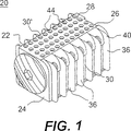
本発明を実施例を参照して詳しく説明する。図中、28、28’のようなダッシュを付記した同じ参照番号は同じインプラントの同じ部分に対して参照されるものとする。
図1及び図2A〜図2Fを参照するに、本発明の好ましい実施例に従う椎体間融合用のインプラントが全体を番号20で示されている。インプラントは、挿通端部24と、後端部26と、対向する各側壁28、28’と、対向する上方壁及び下方壁30、30’とを含む胴部22を有する。胴部22の各側壁28、28’は、各接合部位置で上方壁及び下方壁30、30’と交差する。各接合部は、直径位置で対向する2つの角部32、32’と、直径位置で対向する弧状部34、34’とであるのが好ましい。上方壁及び下方壁30、30’の各一方から外側方向に指状突起、即ちフィン36、36’が伸延し、これらの指状突起36、36’が、インプラント20を回転した場合に隣り合う各椎体の終板に貫入するようになっており、一方、上方壁及び下方壁30、30’は隣り合う各椎体の終板を支持する。
【0021】
本発明のインプラント20の構造的特徴部分の機能を強調するために、インプラントの1実施例の好ましい使用方法を簡単に説明する。
円盤状空間を破除して示す図3Aを参照するに、インプラント20が、円盤状空間内に完全に収納されるまで直線方向に前進され、側壁28、28’が隣り合う円盤状空間の各椎体の各終板と対向する状態とされている。インプラント20の弧状部34、34’が、インプラント20を長手方向軸線を中心として90°回転させた場合に、立法形の、台形の、あるいはその他形状であるインプラントの胴部の寸法形状が、インプラント20の胴部22よりも高くならず、その“高さ寸法”がインプラント20のもっと低い上方壁及び下方壁30、30’の間の寸法となることを保証する。この、図3Bに最も良く示される特徴により、上方壁及び下方壁30、30’は、隣り合う各椎体の円盤状空間を過剰に伸張させることなくあるいは損傷させることなく、これらの各椎体の各終板と接触し且つ支持する状態に配置されるようになる。“過剰に伸張させることなく”なる表現の意味の曖昧化を回避するために、この表面及び個々の文言は本明細書内では通常あるいは普通に使用されるようには使用されず、本件出願での定義においてのみ使用されるものとする。
【0022】
図3Cの、インプラント20の胴部22の好ましい実施例の断面の幾何学的形態の概略図に最も良く示されるように、インプラント20は、対向する各側壁28、28’と、上方壁及び下方壁30、30’と、高さ寸法“X”と、幅寸法“Y”と、短いあるいは短縮された斜辺“RH”とを有している。短縮された斜辺RHは、改変されない斜辺Hよりもインプラント20の高さ寸法Xにずっと近い寸法となっている。高さ寸法Xは幅寸法Yよりもずっと大きいものとして示されるが、これは1例に過ぎず、限定的なものではない。高さ寸法Xはインプラント20の長さあるいは任意部分に沿った幅寸法Yと等しくあるいは若干短くすることもできる。
【0023】
短縮された斜辺RHは、本実施例では斜辺Hよりもずっと短く、かくして、インプラント20を挿通位置から展開位置へと、本プロセス中に過剰な伸延を生じさせることなく回転させることができる。短縮された斜辺RHは本実施例では弓形に例示されているが、この短縮された斜辺RHを形成するためのインプラント20の胴部22の形態は、本発明の意図する目的のために十分な寸法形状の回転された斜辺RHが得られる限りに於いて、弧状部分、アール、面取り、角度付けした一連の表面その他任意の形状を含む色々な形態のものとすることができる。短縮された斜辺RHは、インプラント20の胴部22の高さ寸法Xよりは著しく大きくなく、高さ寸法THと等しいあるいはそれ未満の寸法の対角線を有する。短縮された斜辺RHは、フィン36、36’を含むインプラント20の全高THより短く、またもっと好ましくは、インプラント20の、フィン36、36’の全高THよりもずっと短い対角線をも有する。
【0024】
斜辺(真の斜辺)は、直角三角形の直角と対向する側辺である。ここで、斜辺あるいは短縮された斜辺とは、インプラントの、真の斜辺に重なる、対角線方向に対向する各部分間における理論線の対角線方向寸法に対して参照されるものとする。側壁28、28’と上方壁及び下方壁30、30’は交差される必要はないが、実際上は、各側辺が側壁28’及び下方壁30’に夫々相当する状態で形成される直角三角形の真の斜辺と重なり且つもっと短い理論線を形成させるための例として、逃げ、アール、あるいは面取り構成を有し得る。図3Cに示されるように、斜辺Hは、胴部22上で、側壁28’と下方壁30’とを各平面内で仮に延長させて図3CのX及びYで表すように直角に交差させた場合に形成される直角を横断する、点32及び32’間の線の寸法を表す。短縮された斜辺RHは、理論的な直角三角形の角部がアール付けした接合部であることから、胴部22上の点34、34、間の線の寸法を表す。斜辺を、直角を横断するものとして参照したが、側壁と上方壁及び下方壁が本発明の目的上、直角以外の角度で交差する場合、90°以外の角度によって形成される三角形の長い側辺を斜辺と称するものとする。
【0025】
短縮された斜辺RHが高さ寸法Xよりも若干大きい実施例により、インプラント20を然るべき位置に錠止するオーバーセンター効果の利益が提供される。この場合、インプラント20を回転し、短縮された斜辺RHからなる対角線を通過させると、インプラントを最終の展開位置から初期の挿通位置初期に逆回転させるためには、短縮された斜辺RHを高さ寸法Hと等しくあるいはそれ未満とした場合の実施例におけるよりもずっと大きな力が必要となる。
フィン36、36’の高さ寸法はインプラントの胴部の上方壁及び下方壁30、30’間で測った高さ寸法よりもずっと高い。フィン36、36’は、回転操作によって終板を貫いて駆動された後、隣り合う各椎体の内部に位置付けられる。フィン36、36’を椎体の海綿骨質領域内に突き刺すことにより、インプラントを終板下部の骨の血管質にアクセス可能とし、かくして、フィン36、36’が椎体内でアンカーとして作用する状態での、インプラント20の著しい安定性を提供させ得るようになる。フィン36、36’によって、各椎体のインプラント20と接触する表面積は平坦な表面と比較して大きく増大される。
【0026】
インプラント20の上方壁及び下方壁30、30’は、椎体の終板領域の骨を支持するような形態とされる。既に伸張され、その高さ寸法が胴部22の高さ寸法に相当する円盤状空間にインプラント20を挿通すると、胴部22から突出するフィン36、36’が各端部プレートを通して回転し、椎体内に駆動される。フィン36、36’によるこの切削作用は、フィン36、36’の前縁部の形状を尖らせる、鋭利化する、あるいはその両方により更に増長され得る。
【0027】
インプラント20の構造上、上方壁及び下方壁30、30’を、その間部分の距離が、最適状態に伸張された円盤状空間の高さ寸法に相当するような形態とすることができる。上方壁及び下方壁30、30’は、隣り合う各椎体の終板と一致する表面形態を有するものとして形成し、かくして、各椎体とインプラントとを最適状態で接触及び支持させることができる。上方壁及び下方壁30、30’を貫く、少なくとも1つの、あるいは複数の開口を設け得る。これにより、インプラントを貫いて隣り合う各椎体の一方から他方へと骨が連続的に成長できるようになり、かくして各椎体を相互に融合させることができるようになる。インプラントの各側壁28、28’は、開口を1つあるいは複数有し得、あるいは有さなくとも良い。
図1及び図1Aに示すように、各側壁28、28’はインプラント20を脊椎内に挿通するに際し、隣り合う各椎体と接触するような間隔を有するのが好ましい。各側壁28、28’は相互に全体に平行である。
【0028】
直径位置で対向する弧状部34、34’は、必ずしもそうする必要はないが、複数半径からなる複数の弧状部として形成するのが好ましい。弧状部34、34’は、図1及び図2Eに示すような同一半径のものとするのが更に好ましく、同一円の弧状部とするのが最も好ましい。各弧状部34、34’は同一円の四分円を含み得る。弧状部34、34’間の距離は、上方壁及び下方壁30、30’間の距離に近似し、かくして、インプラント20をその初期の挿通位置から最終の展開位置に回転させた場合、隣り合う各椎体間の空間が何ら伸張されず、しかも各椎体が損傷されないことが好ましい。
【0029】
フィン36、36’は、インプラント20の長手方向の中心軸線Lから測定した高さ寸法Hを有する。1実施例では、この高さ寸法Hはインプラント20の一部分に沿ってあるいは長さ全体に於いて実質的に一様なものであり得る。あるいは、フィン36、36’は、上方壁及び下方壁30、30’から測定した、インプラント20の長さ方向に沿って実質的に一定の高さ寸法H’を有し得る。高さ寸法、そしてフィンの形態のその他の変形例は当業者、即ち、脊椎外科医には容易に認識し得よう。フィン36、36’は、インプラント20が回転されるに際して各椎体に貫入するための鋭利な前縁部40、40’を有するのが好ましい。各前縁部40、40’は尖らせる及び又は傾斜付けしても良い。フィン36、36’は、その長さの任意部分に沿って鋭利化し、フィン36、36’が椎体を貫いての海綿質領域内への差し込みを容易化させることができる。フィン36、36’は、インプラント20を然るべき位置にしっかりと錠止するために各後端位置を肉厚化することができる。例えば、フィン36、36’を、異なる形状及び配列のものとしても良い。例えば、例示目的上であってこれに限定するものではないが、フィン36、36’を、上方壁及び下方壁30、30’の少なくとも一部分に沿って等間隔に配置した指状突起の形状のものとすることができる。螺旋の一部或はセグメントであるフィン36、36’、あるいは、インプラントの長さ方向に沿った間隔が不等間隔のフィン36、36’も本発明の範囲内のものとする。フィン36、36’は、本明細書で言及するような意図目的のために好適な様々な形状の任意のものであり得る。
【0030】
図1ではインプラント20は単一方向に回転する形態を有している。図3A及び図3Bに最も良く示されるようなこの例での実施例では、適宜に伸張された空間内でインプラント20を反時計方向に回転させようとすると、角部32、32’間の対角線の長さが円盤状空間の高さ寸法を上回るという事実により、インプラントの回転は阻止されることが分かる。逆に、時計方向では、弧状部34、34’間の対角線が円盤空間の長さ未満あるいは等しいことから、インプラントを回転させることができる。
【0031】
インプラント20の胴部22は中空部分42を含んでいるのが好ましい。この中空部分42は、これに限定するものではないが、任意の様々な形態での骨、ハイドロキシアパタイト、サンゴ、骨形態形成タンパク質、骨芽細胞あるいは骨形成のための細胞を誘導する能力を有する原因物質を含む、融合促進材料を収納するようになっている。本発明のインプラントは、意図目的上好適な且つ人体の脊椎に移植するために適宜の任意の材料から作製することができる。そうした材料には、これに限定するものではないが、骨自体、特に、人間の皮質性骨が含まれる。人間の皮質性骨は、意図目的のための十分な強度を有している限りに於いて、解剖用死体の大腿骨のような部分から入手され得る。本発明のインプラントは、例えば、ラクトン、ポリラクトン、ガラクトン等からの人工骨部品や生物再吸収性(時間と共に分解して人体に吸収される)のプラスチック、あるいは、骨片どうしを結合して、十分な強度を有し且つ脊椎融合用のインプラントを介して椎体を融合する意図目的のために十分長い期間作用する材料を形成することのできる、任意のそうしたプラスチックを含む新規な材料から作製することができる。そうした新規な材料の中では、必ずしもそうである必要はないが、好ましくは長さが幅寸法よりも著しく大きい、フィブリスの形態を有するようにした、カーボンファイバ配合物によく似た皮質ストリップ状の人間の骨片が好ましい。これらのフィブリスはランダム配置され、層化されるかあるいは、シート状、あるいはパッドあるいはメッシュ状に織られ、再吸収性プラスチックと結合されてインプラントの材料を形成する。インプラントは、材料から注型され、機械加工され、あるいはそれらの組み合わせにより形成される。
【0032】
先に言及したように、インプラント20は少なくとも1つの、あるいは複数の、上方壁及び下方壁30、30’を貫く開口にして、ここではインプラントの胴部を貫いて中空部分42と連通する開口38、38’を有する。これらの開口は、インプラント20を通過する開口を提供すると共に、インプラントの上方壁及び下方壁30、30’を貫き、かくして、インプラントを介しての、隣り合う各椎体の一方から他方への骨の連続的な成長を可能とする。側壁28、28’もまた、これらの側壁を貫いて中空部分42と連通する開口44、44’を含み得る。上方壁及び下方壁30、30’を貫く開口38、38’のみならず、各側壁28、28’の開口44、44’が、インプラントを通しての融合を生じさせるという意図目的のために好適な、任意の寸法形状、形態あるいは配置を有し得ることを容易に認識されよう。本実施例では、開口38、38’及び44、44’の少なくとも幾つかは肉眼で見える寸法、即ち、横断方向寸法が1.0mm以上のものである。本発明のインプラントは、顕微鏡的寸法の開口、即ち約40ミクロン未満の開口も含み得る。顕微鏡的とは、構造の詳細を認識するために拡大操作が必要なほどに十分小さい寸法として定義され、ここでは最大寸法が1mm未満のものとして使用される。
【0033】
インプラント20は、インプラント20の挿通端24に螺合するネジ溝を有するキャップ46を含むのが好ましい。キャップ46は、中空部分42に対するアクセスを提供するべく取り外し自在であり、かくして、中空部分42に任意の天然あるいは人工の、骨伝導性の、骨誘導性の、骨生成性の、その他融合を増長する材料を充填(所望であれば加圧負荷下に)することができるようになる。そうした材料の幾つかの例には、患者若しくはその他から採取した骨、あるいはこれに限定するものではないが、例えば、ヒドロキシアパタイト、ヒドロキシアパタイトトリカルシウムホスフェート、骨形態形成タンパク質のような骨成長誘導材料、あるいは、骨形成のための遺伝子コーディングがある。
【0034】
キャップ46及び又はインプラント20は、コバルトクロム、ステンレス鋼、チタン、プラスチック、セラミック、それらの複合物のような金属を含む人体埋設のために適宜の任意の材料で作製され得、及び又は、これに限定するものではないが、ヒドロキシアパタイトあるいはヒドロキシアパタイトトリカルシウムホスフェートあるいはその他の、骨形成用の細胞及び又は細胞による骨の形成を刺激するための、骨形態形成タンパク質その他の遺伝子材料(骨製造のための遺伝子コーディング)を含む、骨伝導性の、骨誘導性の、骨生成性のあるいはその他の融合増長用の、骨の内部成長を誘起する材料で作製され、及び又は充填され、及び又はコーティングされ得る。キャップ46とインプラント20とは、部分的に、あるいは全体的に生物再吸収性のものであり得る。キャップ46は、ネジ溝連結するものに限定されるものではない。インプラント20及びキャップ46は、意図目的のために且つ当業者に既知の任意の好適な様式下に、一方が他方に協働する状態で係合するように各々構成され得る。インプラントは端部開口が不要であり、様々の実施例においては単一の開口を含み、この開口を通して容易に負荷され得る。キャップ46もまた、このキャップ46をインプラント20と係合させるための、あるいはインプラント20を円盤状空間内及び隣接する各椎体内に挿通及び回転させるための駆動体と協動状態で係合するための形態のものであり得る。キャップ46には、血管質へのアクセス及びそこを通しての骨の成長を提供しつつ、インプラント20内の融合促進物質を保持するための孔を形成することもできる。
【0035】
腰椎で使用するための好ましい実施例では、前後ろに、あるいは後ろ前に配置したインプラント20は、26〜28mmを好ましい長さとする状態での、約20〜34mmの範囲の全長を有する。インプラント22の、上方壁及び下方壁30、30’間の距離として定義される胴部22は、腰椎で使用する場合は約6〜20mmの高さ寸法を有する。この高さ寸法はインプラントの長さ次第で変化させることができる。フィン36、36’は、胴部22から測定して、1〜5mmの範囲の高さ寸法を有するのが好ましい。側壁28、28’は、約6〜20mmの範囲の距離、相互に離間しているのが好ましい。フィン36は、上方壁及び下方壁30、30’から伸延され、フィン36の先端からフィン36’の先端までの距離は、上方壁及び下方壁30、30’間の距離よりも大きい。頸椎用のインプラントは長さが10〜22mmであり、胴部の高さ寸法が5〜12mm、フィンの高さ寸法が0.5〜2.5mm、胴部の幅寸法は5〜12mmであるのが好ましい。
【0036】
本発明の好ましい実施例には、インプラント駆動体係合手段と係合するための手段が含まれる。これに限定するものではないが、この係合手段は、インプラント20の後端部26に位置付けられ、インプラントを挿通させるに先立って全負荷状態とすることができることが好ましい。インプラント駆動体係合手段は、インプラント20をインプラント駆動体に固定可能とし、かくして、駆動体を不慮に脱係合させることなく、押し引き、のみならず回転できるようにするものであることも好ましい。そうしたインプラント駆動体係合手段の一例が図2Dに示される。図2Dでは、インプラント20はその後端部26の位置に、挿通機器を受けるための凹型の長孔48を有する。長孔48は、インプラント20を挿通するに際して使用するための機器をネジ取り付けするためのネジ溝付き開口50を有する。その他の数多くの形式の係合手段を使用し得、それらも本発明の範囲内のものとする。
【0037】
図4及び図5A〜図5E、特に図5Aを参照して説明する本発明の他の好ましい実施例では、インプラント120が、胴部122の挿通端部124から後端部126にかけて相互に角度的に拡開する関係で配置された上方壁及び下方壁130、130’を含んでいる。この拡開関係により、脊椎の前側から挿通した場合における、腰椎あるいは頸椎のセグメントの前湾症が保全され及び又は修復される。図4のインプラント120は、このインプラント120の長手方向の中心軸線Lから測定した高さ寸法Hが実質的に一様なフィン136、136’を有し、かくして、フィン136、136’の全高は長手方向の中心軸線Lと実質的に平行な寸法形状を有する。フィン136、136’の、上方壁及び下方壁130、130’から測定した高さ寸法H’は、インプラント120の長さ方向に沿って変化する。あるいは、フィン136、136’の、インプラント120の長手方向の中心軸線Lから測定した高さ寸法Hはインプラント120の長さ方向に於いて変化され得る。
【0038】
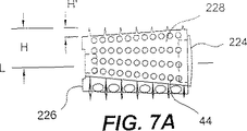
図6及び図7A〜図7Eを参照して以下に説明する本発明の更に他の好ましい実施例では、インプラント220は上方壁及び下方壁230、230’が、胴部222の挿通端部224から後端部226にかけて角度的に収縮する関係で配置されている。本実施例では、脊椎の挿通位置のセグメントでの自然の前湾症を修復するべく、インプラント220を脊椎の後方側から挿通した場合に、インプラント220の胴部222が挿通端部224に最も近い位置の高さ寸法が最も高く、後端部226に最も近い位置の高さ寸法が最小である。そうした修復は、インプラント220がその側面を下にして円盤状空間に導入されること、及び、胴部222の側面から側面にかけての寸法形状が好ましくは一様であるという事実により容易化される。
【0039】
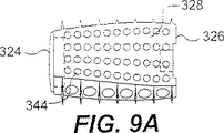
本発明の、図8及び図9A〜図9Eを参照して以下に説明する更に他の実施例では、インプラント320は、融合するべき隣り合う各椎体の各終板の本来の輪郭と実質的に合致する形態に全体的に解剖学的に形状付けされた上方壁及び下方壁330、330’を含んでいる。この解剖学的形状は図8及び図9Aに最も良く示され、上方壁及び下方壁330、330’は、挿通端部324から後端部326にかけて湾曲状態で配向されている。この、上方壁及び下方壁330、330’における全体的に解剖学的な形状は、インプラント320の側面から側面にかけての輪郭にも含まれ得る。
【0040】
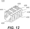
図10及び図11A〜図11Dに示される本発明の他の実施例では、インプラント420は、インプラントを時計及び反時計の何れの方向にも回転させ得るようにアール付けされた、直径位置で対向する4つの接合部を含み得る。インプラント420のこのアール付けされた接合部は、円の一部に限定される必要はない。あるいは、これらの接合部をテーパ付けし、若しくは、その他幾つかの様式で、先に説明したアール付けされた領域に類似する様式で作用するための逃げ領域あるいは切り欠き領域を設け、かくして、短縮された斜辺が、対角線方向に対向する他の接合部間の他の斜辺、即ち、短くされず、改変されず、あるいは、理論的な斜辺若しくは、短縮された斜辺よりも少ない程度に短縮された少なくとも1つの斜辺であるところの他の斜辺よりも実質的に短くなるようにすることができる。
【0041】
図12及び図13Bのインプラント420では、上方の壁430を貫いてインプラントに入り、下方の壁430’の開口438’を貫く3つの大きな開口438が使用される。これらの開口により、インプラント420を通しての、隣り合う各椎体間での骨の連続的な成長が許容される。上方壁及び下方壁430、430’は、図示されるよりも少ないあるいは多い数の開口438、438’を有し得る。そうした別態様は、インプラントの主たる特徴ではない端部開口に頼ることなく、骨のような骨形成性材料を容易に装填し易い。
【0042】
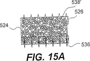
図14及び図15A〜図15Dに示す本発明の他の好ましい実施例では、インプラント520は多孔質材料から構成され、その表面には一般に1.0あるいはそれ未満の直径の複数の開口538、538’が設けられている。開口538、538’は、インプラント520全体を貫くチャンネルの各端部であり、かくして、上方壁及び下方壁530、530’間を通しての、各椎体間での骨の成長が許容される。インプラント520はその多孔質性によって、融合促進材料を保持し得る他に、隣り合う各椎体間に対面して接触し且つ係合する表面積が大きくなる。表面積及び接触面積が共に大きくなることで、インプラント520は椎体間の融合プロセスを一層促進する。この特定のインプラントでは、外側表面552の孔の少なくとも有効部分は直径が50〜500ミクロンの範囲内のものであり、中でも250〜500ミクロンの直径の部分が有効である。インプラント520はその多孔質性故に、宿主における骨形成を誘起するための生物活性の融合促進物質、例えば、骨形態形成タンパク質あるいは遺伝子材料のコーティングもし易い。そうした遺伝子材料には、シトシン、グアニン、アデニン、チミン(CGAT)からなる核酸シーケンスが含まれる。図14及び図15〜図15Dではインプラント520は中実のものとして示されるが、インプラント520を実質的に中空のあるいは部分的に中空のものとして作製することもできる。
【0043】
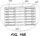
図16A及び図16Bには、先に第3のインプラント820あるいは中間インプラントとして参照した、本発明の別態様が示される。この第3のインプラントは、上述した各実施例に従う第1のインプラント620及び第2のインプラント720間で使用するためのものである。インプラント組み合わせの好ましい実施例では、第1のインプラント620が、例示目的のみに於いて第1の方向に回転する形態のものとされ、第2のインプラント720が、やはり例示目的のみに於いて、第1の方向と反対の第2の方向に回転する形態のものとされる。第1のインプラント620及び第2のインプラント720の各々は、より中心的な位置から、より横方向の位置に回転する。かくして、図16Cに最も良く示されるように、本実施例では第1のインプラント620は時計方向に回転し、第2のインプラント720は半時計方向に回転する。第3のインプラント820は、第1及び第2の各インプラント620、720の間に配置される形態とされ、第1及び第2の各インプラント620、720の各隣り合う側壁628、728と接触するための接触表面860、860’を夫々有している。
【0044】
図17及び図18A〜図18Dに最も良く示されるように、第3のインプラント820は、隣り合う各椎体を通しての骨の成長を許容するための開口838、838’と、第3のインプラント820と第1及び第2の各インプラント620、720との間での血管質及び骨の成長を許容するための開口844及び844’を各側壁828、828’に有している。第3のインプラント820は、隣り合う各椎体と接触するために上方壁及び下方壁830及び830’を既に正しく配向した脊椎に挿通することから、回転しやすいような形態のものとはされない。上方の壁830及び下方の壁830’は、隣り合う各椎体と係合するための嶺部864その他の表面突起を含むのが好ましい。第3のインプラント820の側壁828、828’は、第1のインプラント628及び第2のインプラント720の夫々の側壁628及び728’上の相補する表面突起と係合するための表面突起を含む。本実施例は、第3のインプラント820を第1及び第2の各インプラント620、720間で容易に摺動させ得るが、しかし挿通とは逆の方向への抜けに対しては抵抗する前面ラチェット機構が形成されるのが好ましい。図16B及び図18Eには、第3のインプラント820の側壁の前面ラチェット機構が第1及び第2の各インプラント620、720の側壁の逆向きのラチェット機構と協働してこれら3つのインプラントを並列結合する状況が示される。
【0045】
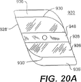
図20A及び図20Bに例示される本発明の好ましい他の実施例では、インプラント920が、初期の挿通位置から90°未満の角度に於いて最終の展開位置に回転される形態を有している。本発明のこの実施例は、約70度の角度回転を有するのが好ましい。90°未満の角度で回転するための形態を有するインプラントは、90°回転する形態の匹敵するインプラントよりも上方壁及び下方壁930、930’と接触する表面積が大きくなり得る。
【0046】
図21に示す本発明の更に他の好ましい実施例では、インプラント1020は、他のインプラント112と合致する形態の少なくとも1つの側壁1028を有している。実際上、図21には、インプラント1120と協働して合致するための少なくとも1つの凹型の側壁1028を有し、筒状の、部分的に筒状の、テーパ付け、ネジ溝付け、あるいは押し込み式の何れかとした、椎体間で使用するための本発明の実施例の後端面図が例示される。側壁1028は、インプラント1120を収受するために凹型とし得、あるいは、インプラント1020及び1120の合計幅寸法がこれらインプラントの各最大幅寸法を合わせた値よりも小さくなるようにするための開口を、または開口でない場合には逃げ部を提供する不完全形状とすることができる。あるいは、図22に示す更に他の実施例では、隣り合うネジ溝付けした椎体間用のインプラント1320からのネジ溝を協動状態で受けるようにした、少なくとも1つの側壁1228内の溝1280を有するインプラント1220を含んでいる。インプラント1320はテーパ付けした設計形状を有するが、多少とも円筒形状とし、また、表面突起をネジ溝以外のものとすることもできる。
【0047】
本発明の幾つかの好ましい実施例を説明したが、以下に、本発明のインプラントを展開させるための方法を詳しく説明する。本発明の方法には、隣り合う各椎体間から円盤の少なくとも一部分を除去することにより、これらの隣り合う各椎体の終板の少なくとも一部を露出させること、挿通端部と、後端部と、側隙と、上方壁及び下方壁と、必ずしもそうである必要はないが、対向する上下の前記壁から外側に伸延する形態であるのが好ましい突起と、を有する第1のインプラントを提供すること、が含まれる。上方壁及び下方壁は、これらの上方壁及び下方壁を貫いて伸延する少なくとも1つの、あるいは複数の開口を有し、かくして、隣り合う各椎体の一方から他方へと、このインプラントを貫いて骨を連続的に成長させることができるのが好ましい。インプラントは、各側壁が、対向する接合部位置で上方壁及び下方壁と交差する状態での断面を含む。前記接合部の2つは、直径位置で対向する弧状部であるのが好ましい。本発明の方法には、隣り合う各椎体間で第1のインプラントを、その各側壁を各椎体の終板と対向する状態下に直線的に前進させ、次いで、この第1のインプラントを90°回転させて展開位置とし、隣り合う各椎体の終板にフィンを貫入させるインプラント挿通段階が含まれる。インプラントは、この展開された状態では、フィンを突出させた上方壁及び下方壁が隣り合う各椎体の終板領域と接触し、また、この隣り合う各椎体の終板領域を介して、終板自体を支持する。
【0048】
インプラント挿通段階は、インプラントを長手方向軸線を中心として90°回転することにより、隣り合う各椎体を相互に相対角度位置に位置決めすることを含み得る。本方法には、第1のインプラントに、このインプラントを挿通する以前に、骨形成性材料を充填することが含まれ得る。また本方法には、挿通に先立ってインプラントの内部に融合促進材料を圧入することが更に含まれ得る。インサートを回転させるに際しては、インサートを、直径位置で対向し複数半径を有する2つの弧状部を、隣り合う各椎体と夫々最も接近する方向に回転を開始させる2次段階が更に含まれ得る。更に、この回転に際しては、挿通後の第1のインプラントを、隣り合う各椎体を実質的に追加的に伸張させることなく展開位置に回転させることが含まれ得る。
【0049】
本発明の方法には、第1のインプラントに駆動体を取り付けることが更に含まれ得る。駆動体は、インプラントを時計及び反時計の両方向に回転させる間、インプラントを押し引きし得るものであるのが好ましい。本発明には、この駆動体を使用して、インプラントを、円盤貫通用の延長部付きのあるいは延長部無しの、あるいは、米国特許第5,484,437号及び同第5,797,909号に記載されるような伸延装置と組み合わせたガードを通して挿通することが更に含まれ得る。
【0050】
本発明の方法には、挿通端部と、後端部と、側壁と、上方壁及び下方壁と、これら上方壁及び下方壁から外側方向に伸延するフィンと、を有する第2のインプラントを提供することが更に含まれ得る。上方壁及び下方壁は、これら各壁を貫く開口にして、これらの開口並びに、椎体の一方から他方への、インプラントを貫いての骨の連続成長を許容する形態の開口を有するのが好ましい。第2のインプラントは、各側壁が、上方壁及び下方壁の接合部位置で交差する断面を有する。接合部の2つは直径方向に対向する弧状部分であるのが好ましい。第2のインプラントは、その各側壁が隣り合う各椎体に隣り合う方向に向いた状態でこれら隣り合う各椎体間に挿通され、次いで展開位置へと90°回転される。かくして、上方壁及び下方壁は隣り合う各椎体と接触してこれを支持し、一方、上方壁及び下方壁から伸延するフィンが各椎体の終板を貫通するように駆動される。インプラントが回転されるとフィンが各椎体の物質中に駆動される。
本方法の2次的段階として、第1のインプラントを第1の方向に90°回転させ、一方、第2のインプラントを第1の方向と同じ方向若しくは反対方向の何れかに回転させて展開させ得る。
【0051】
本発明の方法には、第1のインプラント及び第2のインプラントをラテラライズ、即ち横方向移動させ、これら各インプラント間に空間を提供させることが更に含まれ得る。本発明の方法には、この空間内に、第3のインプラントにして、直線方向に前進させることにより挿通される設計形状を有するが、回転させることにより然るべく配置するような設計形状は有さない点で第1及び第2の各インプラントとは構造の異なる、特殊な第3のインプラントを配置することが更に含まれ得る。この特殊構造の第3のインプラントは、隣り合う各椎体の各々と接触するための上方壁及び下方壁を有するのが好ましい。これらの上方壁及び下方壁は、骨が、隣り合う各椎体の一方から他方にむけて第3のインプラントを貫いて成長することができるようにするための少なくとも1つの開口を有するのが好ましい。第3のインプラントは、第1及び第2の各インプラント間で、且つ、対向する上方壁及び下方壁を隣り合う各椎体に向けた状態で、隣り合う各椎体間に挿通されるのが好ましい。第3のインプラントを挿通する段階には、第1及び第2の各インプラントを第3のインプラントの各側壁と接触させる2次的段階と、この第3のインプラントを第1及び第2の各インプラントに固定する2次的段階とが含まれ得る。第3のインプラントを第1及び第2の各インプラントに固定する2次的段階には、第1〜第3の各インプラントの各側壁に沿って、少なくとも、これらの各インプラントが相互に接触する部分に協働する係合表面を提供する2次的段階が含まれるのが好ましい。
【0052】
各インプラントを90°回転させる間、各インプラントは内部空間を過剰に伸張させることはなく、しかも尚、隣り合う各椎体を貫く、インプラント自体の幅寸法の1.5倍のものであり得るフィンのための通路を創出する。第1〜第3の各インプラントを円盤状空間に挿通させると、第1及び第2の各インプラントが先に説明したようにそれらの幅寸法の約50パーセントの寸法に於いて横方向に移動し、第3のインプラントのための、第1及び第2の各インプラントと同じ幅寸法の空間を創出する。第3のインプラントは、第1及び第2の各インプラントの各々が切削した50パーセントの追加領域を使用する。隣り合う各椎体に第1及び第2の各インプラントのフィンによって切削された軌道は、これらのインプラントを横方向に摺動可能とするための、抵抗の小さい通路として作用する。本発明の範囲を逸脱することなく、第1及び第2の各インプラントの幅寸法よりも幅寸法の大きい第3のインプラントを使用することもできる。
【0053】
これらの各インプラントを挿通するための方法には、インプラントと類似の模様付けを施した、しかしインプラントよりも強度が高いか、若しくはもっと鋭利な材料で作製した切削工具を使用することも含まれ得る。例えば、仮にインプラントをカーボンファイバあるいは生物再吸収性のプラスチックあるいは骨から作製した場合、回転ブローチのような切削工具を使用して、インプラントのフィンが占有するがフィンの実際の切削作用は生じない通路を切削するのが望ましい。
本発明の方法には、インプラントを挿通する以前に、終板自体の最も外側の面の深さの血管質にアクセスするために、終板上で、少なくとも皮質が部分的に除去されるまでの、終板上でのスクラッピングあるいはそうでない場合には加工段階が更に含まれ得る。この加工段階には、環状繊維及び髄核を共に含む十分な量の円盤材料を隣り合う各椎体間から除去することによる、隣り合う各椎体の各終板を露出させる段階を含み得る。第1のインプラントを提供する段階には、第1のインプラントにして、この第1のインプラントの胴部の挿通端部及び後端部の少なくとも一方が開口を通して中空部分と連通され且つキャップと協動状態で係合するようになっている第1のインプラントを提供することが含まれ得る。第1のインプラントを提供する段階には、第1のインプラントを、インプラントの胴部の挿通端部及び後端部の少なくとも一方における開口を閉じるための取り外し自在のキャップとの組み合わせに於いて提供することも含まれ得る。本発明の方法には、インプラントに骨形成性材料を圧縮充填あるいは装填する段階が更に含まれ得る。
【0054】
インプラント挿通段階には、隣り合う各椎体間でインプラントを直線的に前進させる2次的段階が含まれる。この直線的前進には、隣り合う各椎体間でインプラントを押す、あるいは衝撃を使用して各椎体間に駆動することが含まれる。本発明の方法には、隣り合う各椎体を、インプラントの挿通段階に先立って、インプラントを挿通させるために十分伸張させることが更に含まれ得る。本発明の方法には、インサート挿通段階に先立ち、各椎体の後方側の硬膜サックを後退させる段階が更に含まれ得る。インプラント挿通段階は、脊椎の前面側から実施することが可能であり、この場合、インプラント挿通段階に先だって隣り合う各椎体の前面側の多数の血管が後退される。本発明の方法には、隣り合う各椎体間に回転ブローチを挿通する段階が更に含まれ得る。回転ブローチは、隣り合う各椎体と接触し状態で摺動するための対向する側面と、回転ブローチの長手方向軸線を横断して隣り合う各椎体の各々の内部にブローチ切削するための切削用部分とを有する。ブローチ切削段階には、回転ブローチを回転させ、切削要素を回転ブローチの切削部分の長さ方向に沿って回転させし、回転ブローチの長手方向軸線を横断する方向で隣り合う各椎体の各々の内部に駆動することが含まれる。
【0055】
(発明の効果)
椎体から椎体へとインプラントを通して骨を成長させることのできる、椎体間融合用のインプラントを提供することである。
【図面の簡単な説明】
【図1】 初期の挿通位置に配向され、隣り合う各椎体間の最終の展開位置に向けて時計方向に回転する形態を有する、本発明の特徴の幾つかを組み込んだ椎体間融合用のインプラントの1実施例の斜視図である。
【図2A】 インプラントを椎体間の最終の展開位置に配向した状態での図1のインプラントの側面図である。
【図2B】 インプラントを椎体間の最終の展開位置に配向した状態での図1のインプラントの下方からの平面図である。
【図2C】 インプラントを椎体間の最終の展開位置に配向した状態での図1のインプラントの上方からの平面図である。
【図2D】 インプラントを椎体間の最終の展開位置に配向した状態での図1のインプラントの後端面図である。
【図2E】 インプラントを椎体間の最終の展開位置に配向した状態での図1のインプラントの挿通端図である。
【図2F】 中空部分へのアクセスを提供するための、後端部における開口を例示する図2A〜図2Eのインプラントを挿通端方向から見た正面図である。
【図3A】 本発明のインプラントを初期の挿通位置に配向した状態での、脊椎セグメント(2つの椎体及びその間に介在する円盤状空間)の部分の斜視図である。
【図3B】 図3Bのインプラントを展開位置に配向し、インプラントの2つの指状突起を点線で示す、図3Aの脊椎部分の斜視図である。
【図3C】 図1及び図2のインプラントの胴部の断面の幾何学的形態を表す概略図である。
【図4】 初期の挿通位置に配向され、円盤状空間内で時計方向に回転する形態を有し、上方壁及び下方壁が、隣り合う各椎体の角形成を誘起するために相互に傾斜された本発明のインプラントの別態様の斜視図である。
【図5A】 展開位置に配向された図4のインプラントの側面図である。
【図5B】 展開位置に配向された図4のインプラントの下方からの平面図である。
【図5C】 展開位置に配向された図4のインプラントの上方からの平面図である。
【図5D】 展開位置に配向された図4のインプラントの後端面図である。
【図5E】 展開位置に配向された図4のインプラントの挿通端面図である。
【図6】 初期の挿通位置に配向され、円盤状空間内で時計方向に回転する形態とされ、上方壁及び下方壁が、隣り合う各椎体間の角度付けを誘起するために相互に傾斜された、後方挿通用の、本発明のインプラントの別態様の斜視図である。
【図7A】 展開位置に配向された、図6のインプラントの側面図である。
【図7B】 展開位置に配向された、図6のインプラントの下方からの平面図である。
【図7C】 展開位置に配向された、図6のインプラントの上方からの平面図である。
【図7D】 展開位置に配向された、図6のインプラントの後端面図である。
【図7E】 展開位置に配向された、図6のインプラントの挿通端面図である。
【図8】 初期の挿通位置に配向され、融合するべき2つの隣り合う各椎体の各終板の自然の輪郭に全体的に良好に合致させるための形態とされた、解剖学的に形状付けされた上方壁及び下方壁を有する、本発明のインプラントの別態様の斜視図である。
【図9A】 展開位置に配向された、図8のインプラントの側面図である。
【図9B】 展開位置に配向された、図8のインプラントの上方からの平面図である。
【図9C】 展開位置に配向された、図8のインプラントの下方からの平面面図である。
【図9D】 展開位置に配向された、図8のインプラントの後端面図である。
【図9E】 展開位置に配向された、図8のインプラントの挿通端面図である。
【図10】 初期の挿通位置に配向され、円盤状空間内で両方向に回転して最終の展開位置に向かう形態とされた、本発明のインプラントの別態様の斜視図である。
【図11A】 展開位置に配向した状態での、図10のインプラントの側面図である。
【図11B】 展開位置に配向した状態での、図10のインプラントの下方からの平面図である。
【図11C】 展開位置に配向した状態での、図10のインプラントの後端面図である。
【図11D】 展開位置に配向した状態での、図10のインプラントの挿通端面図である。
【図12】 初期の挿通位置に配向され、円盤状空間内で両方向に回転して最終の展開位置に向かう形態とされた、本発明のインプラントの別態様の斜視図である。
【図13A】 展開位置に配向された、図12のインプラントの側面図である。
【図13B】 展開位置に配向された、図12のインプラントの下方からの平面図である。
【図13C】 展開位置に配向された、図12のインプラントの後端面図である。
【図13D】 展開位置に配向された、図12のインプラントの挿通端面図である。
【図14】 初期の挿通位置に配向され、多孔質材料で作製された本発明のインプラントの別態様の斜視図である。
【図15A】 展開位置に配向した状態での、図14のインプラントの側面図である。
【図15B】 展開位置に配向した状態での、図14のインプラントの上方からの平面図である。
【図15C】 展開位置に配向した状態での、図14のインプラントの後端面図である。
【図15D】 展開位置に配向した状態での、図14のインプラントの挿通端面図である。
【図16A】 非回転式の第3のインプラントを間部分に挿通するべく位置付け且つ相互に離間して位置決めされた、時計方向回転式のインプラント及び半時計方向回転式のインプラントの平面図である。
【図16B】 円盤状空間内で、第3のインプラントを時計方向回転式のインプラントと半時計方向回転式のインプラントとの間に展開させた状態での図16Aの各インプラントの平面図である。
【図16C】 隣り合う各椎体間で展開された、図16A及び図16Bの各インプラントの後端面図である。
【図17】 本発明の、図16A及び図16Bに示す第3のインプラントの、側面を下にして配置した状態での斜視図である。
【図18A】 展開位置に配向した状態での、図17の第3のインプラントの側面図である。
【図18B】 展開位置に配向した状態での、図17の第3のインプラントの上方からの平面図である。
【図18C】 展開位置に配向した状態での、図17の第3のインプラントの後端面図である。
【図18D】 展開位置に配向した状態での、図17の第3のインプラントの挿通端面図である。
【図18E】 図18Bの第3のインプラントの協動用側面の部分拡大図である。
【図19A】 図17、図18A、図18B及び図18Eに示す第3のインプラントの協動用表面と係合するための協動用表面を有する、本発明の1実施例のインプラントの側面図である。
【図19B】 図17、図18A、図18B及び図18Eに示す第3のインプラントの協動用表面と係合するための協動用表面を有する、本発明の1実施例のインプラントの上方からの平面図である。
【図19C】 図19Bのインプラントの協動用表面の部分拡大図である。
【図20A】 本発明のインプラントの別態様の後端面図である。
【図20B】 図20Aのインプラントの別態様の挿通端面図である。
【図21】 隣り合うインプラントを協動状態で受ける形態とされた本発明のインプラントの別態様の後端面図である。
【図22】 隣り合うインプラントを協動状態で受ける形態とされた本発明のインプラントの別態様の上方からの平面図である。
【符号の説明】
20、120、220、320、420、520 インプラント
22、122、222、322、422、522 胴部
24、124、224、324、424 挿通端部
26、126、226、326、426 後端部
28、28’、128、128’228、228’、328、328’、428
428’528,528’ 側壁
30、130、230、330、430 上壁
30’130’、230’、330’、430’ 下壁
34、34’ 弧状部
36、136、36’136’ フィン
42 中空部分
44、44’ 開口
46 キャップ
48 長孔
50 ネジ溝付き開口
438、438’ 開口
552 外側表面
820 第3のインプラント
620 第1のインプラント
720 第2のインプラント
838、838’、844、844’ 開口[0001]
(Field of Invention)
The present invention generally relates to an improved implant for fusion between vertebral bodies for fixing adjacent vertebral bodies and a method of expanding the same, and more particularly to the dense endplates and subchondral structures of adjacent vertebral bodies. In order to effectively maintain the structural support of the bone region, the endplate is used to access the subchondral vascular bone to achieve interbody fusion at least partially through the implant itself. The present invention relates to an intervertebral body fusion implant to be penetrated and a method of expanding the same.
[0002]
(Conventional technology)
Interbody fusion is surgically performed by bridging the bone tissue between adjacent vertebral bodies across the discoidal space and performing relative movement between these adjacent vertebral bodies. It is a method to eliminate it. Here, the “disk-shaped space” refers to a space between vertebral bodies that is normally occupied by the vertebra. The vertebral disk, usually located between adjacent vertebral bodies, maintains the space between the vertebral bodies, and a healthy spine allows normal relative movement between the vertebral bodies.
A number of implants to facilitate interbody fusion are described by Croward, Brantigan, Michelson et al., And are known to those skilled in the art. Interbody fusion has also been achieved using bone grafts placed between vertebral bodies, as taught and practiced by Dr. Croward. In general, cylindrical implants, which can be screwed, have the advantage of adapting to easily tuned host bone that penetrates each adjacent vertebral body across the discoid space. Such host bone can be created using a drill, but drilling the bone removes a portion of the endplate and subchondral bone.
[0003]
The human vertebral body has a dense outer cancellous bone (hereinafter also referred to as cortex) hard outer shell and a relatively soft, cancellous inner mass. The portion immediately below the cortex and adjacent to the discoid space is a bone region that will be referred to as the “subchondral zone”. To avoid ambiguity, the outer cortical shell adjacent to the spinal disc (the endplate of bone) and the lower subchondral zone of the cortex are both referred to herein as the “endplate area” of the bone, and For purposes of the present invention, such a definition will be used. The endplate region constitutes the densest bone available to support the fusion implant throughout its length, but when the vertebral body is perforated to remove this endplate region, the implant becomes dense It is much smaller than that of the vertebral body, and it is placed on soft cancellous bone that is much deeper than the endplate.
[0004]
In addition, vertebral fusion implants incorporating a modified cylindrical shape, ie, a tapered cylindrical shape, are also known. However, this tapered implant still requires the use of a drill to create a perforation that traverses the disc space, and eventually a portion of the endplate is removed. As long as the surfaces of these types of implants that contact the upper and lower vertebral bodies are arcuate, the vertebral host floor must be arcuate to obtain the degree of contact required to fuse the implants. Is possible. When the vertebral body is so bowed to receive the implant, the endplate is removed.
It is also known in the art to push a non-cylindrical implant into a disc space after discectomy. Such push-in implants have the benefit of supporting each adjacent vertebral body by contacting a substantial portion of the endplate of the vertebral body, but in a cylindrical screw-in implant that screws into a perforation in each adjacent vertebral body. There is no associated benefit, i.e. the benefit that the implant is finally held more firmly in the fully seated position. Moreover, the vertebral bodies do not fuse unless the endplate is at least partially decorrelated, i.e., processed, to access the vasculature at the depth of the outermost face of the endplate itself.
[0005]
Non-cylindrical vertebral body fusion implants are also known that are inserted between adjacent vertebral bodies and rotated accordingly by 90 °. However, this cross-sectional shape of the implant leads to situations where the vertebral bodies are undesirably overstretched when the implant is rotated, or between the vertebral bodies after rotation. For example, an implant with a roughly square or rectangular cross section can rotate the disk clockwise or counterclockwise to create a discoid space when the implant diagonal forms a right angle (90 °) with the endplate of each adjacent vertebral body. Stretch to the maximum. This amount of extension is greater than when either of the opposing sides of the implant is in contact with each adjacent vertebral body. If the space between adjacent vertebral bodies is too small or the expected extension is too large, the implant cannot be rotated or the vertebral bodies are destroyed. If the space between adjacent vertebral bodies is large enough to allow the implant to rotate, the implant is rotated to its final position and the opposite sides of the implant contact each adjacent vertebral body, but these Since the height dimension between the sides is smaller than the aforementioned diagonal rotating through the same space, the extension occurring between the vertebral bodies is much smaller. It is highly desirable that the extension between the vertebral bodies is within the elastic deformation range. This is because elastic deformation fixes and stabilizes the implant between adjacent vertebral bodies and provides maximum space for the passage and drainage of neural elements through these vertebral body segments.
Thus, while maintaining the endplate between adjacent vertebral bodies, it provides access to the vascularity of the subchondral bone and rotates 90 ° within the discoid space to provide an elastic deformation range of the vertebral bodies. There is a need for an implant for vertebral body fusion that achieves optimal stretching within and does not cause plastic deformation and tissue damage.
[0006]
(Issue to solve)
According to the present invention, an intervertebral body fusion implant is provided that allows bone to grow through the implant between vertebral bodies. The implant according to the invention is designed to be pushed into a discoid space in which the endplate regions of each adjacent vertebral body are substantially preserved. This does not mean that the end plate should be left in its initial state. Rather, the implants contemplated in the preferred embodiments described herein are rather designed for use in a discoidal space that leaves the subplatelet subchondral region in a structurally significant amount. A preferred implant of the present invention, when rotated 90 ° about the longitudinal axis of the implant, is such that the torso portion of the implant is in contact with the endplate region of each adjacent vertebral body, such as fins or blade-like processes. The process is driven and then deployed so as to penetrate into the deeper medial side of these vertebral bones. The problem to be solved by the present invention is to provide an improved implant for vertebral body fusion that can fuse vertebral bodies through an implant. The implant of the present invention is inserted between adjacent vertebral bodies and then rotated 90 ° so that each vertebral body is properly positioned without excessive stretching and pulling away, while Penetration accesses the bone vascularity of the subchondral bone and locks the implant in place, thus stabilizing each adjacent vertebral body with respect to the implant and with respect to each other. Here, “not excessively stretched” is defined as stretching each vertebral body within the range of the elastic bias and without plastically deforming and destroying the tissue. In order to avoid ambiguity in the meaning of “without being overly distracted”, such expressions and individual terms are not intended to be used normally or generally, but are defined only herein. Used as.
[0007]
Another problem to be solved is not necessarily so, but can be inserted through the discoidal space and without the need to drill into each adjacent vertebral body, thus the end of each adjacent vertebral body. To provide an improved implant for interbody fusion that provides substantial access to the subchondral bone vascularity, which is important for interbody fusion, while substantially conserving the disc area. It is.
The objects and benefits of the present invention are described in part below. These challenges and benefits will be apparent in part from their description or may be appreciated through practice of the invention. The objects and advantages of the invention may be realized and attained by means of the elements and combinations particularly pointed out in the appended claims.
The following description is for illustrative purposes only, and is not intended to be limiting, and various modifications within the scope of the present invention may be foreseen in accordance with the teachings thereof.
[0008]
(Means for solving the problem)
In order to solve the above-mentioned problems, according to the present invention, an improved implant for interbody fusion is provided for insertion through a discoid space between adjacent vertebral bodies of a human body. The In one embodiment, the implant has a barrel with an insertion end, a sidewall, an upper wall and a lower wall, where the sidewall is at two corner positions opposed in diameter position and at a diameter position. The cross section intersects with the upper wall and the lower wall at the positions of two arcs opposed to each other. The implant of this example also has one or more fin-like projections extending outwardly from the upper and lower walls so that when the implant is rotated about 90 degrees to the final position between each vertebral body, these A fin-like process penetrates into the end plate of each adjacent vertebral body. The implant can be configured to rotate only in a single direction or in a symmetric direction. When the implant is rotatable in both directions about its longitudinal axis, i.e. symmetrically rotatable, the intersection of each side wall with the upper and lower walls is preferably arcuate. Here, the “side wall” refers to a portion extending between the vertebral bodies after the implant is rotated and finally positioned in the space between the adjacent vertebral bodies. Here, “upper” and “lower” refer to each vertebral body in the head direction and the tail direction when the implant is rotated to the final position in the discoid space, and the fin-like projections. The surface portion that supports each vertebral body by inserting
[0009]
There are various modifications to the implants described above. For illustrative purposes only, the sidewall, upper wall, and lower wall are each generally parallel to one another. The sidewall can be in physical contact with each adjacent vertebral body early in the insertion between the vertebral bodies prior to rotating the implant to its final position. The side walls and / or the upper and lower walls can be configured with openings to allow bone to grow therethrough. The implant can also have a hollow portion that can be loaded with a fusion promoting material to promote fusion between adjacent vertebral bodies. The upper and lower walls can be angled in various directions to accommodate the anterior vertebral bay and / or have a contour that matches the natural contour of each endplate of each adjacent vertebral body. It can have.
[0010]
Implants may be made from any suitable material that is suitable and strong enough to act for the intended purpose within the spine of the human body. These materials include, but are not limited to, cortical bone, bone composites, plastics, carbon fiber and other composites, ceramics, surgical grade implant quality metals such as titanium and titanium alloys, tantalum, Chrome alloys are included. The implant may further include a bioresorbable material and a material that promotes bioactivity, ie, the formation of bone important for fusion. These materials are within the implant material and can be included in the structure of the implant, or can be, but are not limited to, bone morphogenetic proteins, genetic factors ( Genetic material coding to generate bone), osteoblasts and other conversion factors to stimulate and / or activate the formation, recruitment, or formation of cells or cellular mechanisms for bone development.
[0011]
The diametrically opposed joints are preferably arcuate, in particular arcs that can be shaped in different ways. For example, each arc can be of multiple radii, or each can have the same radius. Alternatively, each arc can be the same circular chord or quadrant. Similarly, another junction that is diametrically opposed can be a corner that can form a right angle. This other diametrically opposed joint may be removed, chamfered or rounded if it is desired to rotate the implant in any direction about the longitudinal axis.
[0012]
The fins can have a variety of forms. Another form of fin is a central longitudinal axis through the implant or a height along a portion of the length of the implant as measured from the upper and lower walls of the implant barrel from which the fin protrudes. Includes dimensions that are different, equal, or variable. The fins or protrusions may be variable or have a constant thickness, or the distance between fins may be variable or constant. The fin or process may have a sharp anterior edge and / or posterior surface to facilitate incision into the endplate region of the spine when the implant is rotated, and in a preferred form The leading edge is knife-like, inclined, thin and sharp, and the trailing edge is thick and not sharp. Here, in order to avoid obscuring the meaning of the trunk having the upper and lower surfaces and the fins protruding from the upper and lower surfaces, the upper and lower surfaces and the protruding fins are difficult to distinguish. Even within the scope of this application. Even in this case, there is an area between the fins that is positioned to support each vertebral body at each surface position adjacent to the disc-like space.
[0013]
The implant of the present invention need not be used alone. Rather, the implants of the present invention can be used with complementary implants that provide additional stability and fusion enhancement. The complementary implant is itself novel and constitutes another embodiment of the present invention. For example, a second implant of the type described above can be rotated in the same direction as the first implant (ie, clockwise or counterclockwise), or preferably, in the opposite direction to the first implant. The direction of rotation of the implant depends on the position of the joints that are opposite in diameter, preferably arcuate portions of multiple radii. A preferred embodiment implant having a unidirectional rotational configuration, when rotated about 45 degrees, engages the endplate with a multi-radius arc rather than a corner, thus, this multi-radius Use arc geometry to avoid over-extension.
[0014]
When two such implants are inserted in the disc space between the adjacent vertebral bodies, a special third implant can be inserted between the two implants, but the third implant is seated. A space is created that cannot be rotated for wearing. Therefore, the preferred third complementary implant has a ratchet mechanism on each of the upper and lower surfaces thereof, which engages with the end plate of each adjacent vertebral body to increase the stability in the disc space. Also preferably, each side has a ratchet mechanism that matches a ratchet mechanism similarly spaced on each side wall of each of the first and second implants, and is thus locked into each adjacent vertebral body. Each of these implants is locked in place. Each implant may be interdigitated otherwise. The third implant forcibly pulls the first and second implants apart and is captured in the gap, and thus each of the adjacent vertebral bodies as well as each of the first and second implants. Improve implant and mutual stability. Although a ratchet mechanism is preferred, knurling and other surfaces that mechanically interfit implants to adjacent vertebral bodies and adjacent implants are also within the scope of the present invention.
[0015]
The present invention also provides a method for deploying at least one interbody fusion implant across each discoid space into each adjacent vertebral body in the human spine. The method includes at least a portion between adjacent vertebral bodies from each vertebral body to the endplate of each adjacent vertebral body at a depth that is at least greater than the length of the implant and preferably the length of the implant. With a depth of the above dimensions and a width dimension of at least the same dimension as the height of the implant measured between the fin tips opposite the fin tip, which is the maximum height of the implant Removing the disc, as the first implant, the insertion end, the rear end, the side wall, and the upper wall and the lower side where the projections, which are not necessarily so, preferably extend in the outward direction, respectively. And providing a first implant having a wall. The upper and lower walls pass through the upper and lower walls, and thus at least one or more to allow continuous bone growth through the implant from one side of each adjacent vertebral body to the other. It is preferable to have an opening. The implant includes a cross section where each side wall intersects at the junction of the upper and lower walls. The crossing position of the upper wall and the lower wall is preferably a position of two arcs facing each other in the diameter position. In the method of the present invention, the insert is linearly advanced between adjacent vertebral bodies with each side wall facing the endplate of each adjacent vertebral body and then rotated 90 ° about the longitudinal axis. And moving the surfaces extending from the upper and lower walls into and out of the bones of each adjacent vertebral body, thus penetrating each fin into each endplate of each adjacent vertebral body. . When the implant is deployed, the upper and lower walls from which the fins are distracted are placed in contact and support with the endplates of each adjacent vertebral body.
[0016]
Other embodiments of the invention include removing the disc material as described above, attaching the implant to a hand-held drive device, including but not limited to neural structures, vascular structures, and living organs. A hand-held insertion device that provides contactless access to the space created by distracting any human tissue, and that can provide the implant with both engagement and rotation in a linear direction In the space created between each adjacent vertebral body, with the side face adjacent to the endplate of each adjacent vertebral body, and advance linearly to a sufficient depth that does not protrude from the spine The implant, preferably using an insertion device, to rotate the implant, and thus the joint of the upper wall and the posterior wall, preferably consisting of parts of an arc opposed in diameter Contacting each adjacent vertebral body, continuing to rotate the implant and driving the upper and lower wall fingers into the adjacent surfaces of each adjacent vertebral body until the implant rotates approximately 90 degrees Insertion, and / or disengagement of the rotating tool without reverse rotation of the implant.
[0017]
The present invention has an insertion end portion, a rear end portion, a side wall, and an upper wall and a lower wall formed by extending fins outward. At least the upper wall and the lower wall are formed from a vertebral body to a vertebral body. Providing a second implant having a dimensionally shaped opening sufficient to allow continuous bone growth formed in a structurally significant manner to significantly support a load on the Each side wall of the implant is made to be a joint position between the upper wall and the lower wall, and is intersected at a joint position that is preferably an arcuate portion opposed in diameter, and each side wall is adjacent to each other between adjacent vertebral bodies. Inserting the second implant in an orientation to each mating vertebral body, then rotating the second implant 90 ° to the deployed position, thus making the upper and lower walls the endplate region of each vertebral body In contact with and supporting the upper wall and lower Causing drilled fins extending from the wall to the endplates of each vertebral body, preferably it included stage.
[0018]
As a secondary step in the method, the first implant can be rotated 90 ° in the first direction and deployed to provide a space between the first and second implants. In this method, the first implant is designed in such a manner that the third implant is inserted into the space while being advanced and inserted in a linear direction, but is not properly positioned when rotated. It may further include placing a third implant having a different structure from each of the two implants. This special third implant has a protrusion (ratchet mechanism) on the outer wall for engaging the third implant with each adjacent vertebral body and with the first and second implants. Can be included. The third implant preferably has an upper wall and a lower wall for contacting each adjacent vertebral body. The upper and lower walls preferably have at least one opening to allow continuous bone growth in a mechanically significant manner through the third implant from one to the other of each adjacent vertebral body. . In addition, the preferred secondary stage for use when the implant is made from a material such as cortical bone, carbon fiber or any material that is less strong than a titanium alloy uses a rotating broach or rotating tap. And providing a long hole in each vertebral body for guiding the fin.
[0019]
When the first and second implants are rotated in opposite directions away from each other, the fins cut through the surface of each adjacent vertebral body to a longer path occupied by the implant in the deployed state. . This allows the implant to slide open without chipping over or twisting, or to move forward as the fin slides laterally from the center of the longitudinal axis. In a preferred method, the disc material of the present invention includes a very strong annular fibrous portion that has a tendency to resist each lateral movement of the implant and bring the first and second implants back to the center. Thus, according to the third implant, the first and second implants are pushed apart by the wedge action, provided for themselves and for other implants and provided to each adjacent vertebral body. Very high stability is obtained.
[0020]
(Aspect of the Invention)
The present invention will be described in detail with reference to examples. In the figures, the same reference numbers with dashes such as 28, 28 'are referred to the same parts of the same implant.
1 and 2A-2F, an interbody fusion implant according to a preferred embodiment of the present invention is generally designated 20. The implant has a
[0021]
In order to emphasize the function of the structural features of the
Referring to FIG. 3A, where the discoid space is broken away, the
[0022]
As best shown in the cross-sectional geometry schematic diagram of the preferred embodiment of the
[0023]
The shortened hypotenuse RH is much shorter than the hypotenuse H in this embodiment, and thus the
[0024]
The hypotenuse (true hypotenuse) is the side that faces the right angle of the right triangle. Here, the hypotenuse or shortened hypotenuse is referred to the diagonal dimension of the theoretical line between the diagonally opposite portions of the implant that overlap the true hypotenuse. The
[0025]
An embodiment in which the shortened hypotenuse RH is slightly larger than the height dimension X provides the benefit of an over-center effect that locks the
The height dimension of the
[0026]
The upper and
[0027]
Due to the structure of the
As shown in FIGS. 1 and 1A, each
[0028]
The
[0029]
The
[0030]
In FIG. 1, the
[0031]
The
[0032]
As previously mentioned, the
[0033]
The
[0034]
[0035]
In a preferred embodiment for use with the lumbar spine, the anterior-posterior or anterior-
[0036]
Preferred embodiments of the present invention include means for engaging with implant driver engaging means. Although not limited thereto, the engaging means is preferably positioned at the
[0037]
In another preferred embodiment of the invention described with reference to FIGS. 4 and 5A-5E, and in particular with reference to FIG. 5A, the
[0038]
In yet another preferred embodiment of the present invention described below with reference to FIGS. 6 and 7A-7E, the
[0039]
In yet another embodiment of the present invention described below with reference to FIGS. 8 and 9A-9E, the
[0040]
In another embodiment of the invention shown in FIGS. 10 and 11A-11D, the
[0041]
12 and 13B, three
[0042]
In another preferred embodiment of the present invention shown in FIGS. 14 and 15A-15D, the
[0043]
16A and 16B illustrate another aspect of the present invention, previously referred to as the
[0044]
As best shown in FIGS. 17 and 18A-18D, the
[0045]
In another preferred embodiment of the present invention illustrated in FIGS. 20A and 20B, the
[0046]
In yet another preferred embodiment of the present invention shown in FIG. 21, the
[0047]
Having described several preferred embodiments of the present invention, the following describes in detail the method for deploying the implant of the present invention. In the method of the present invention, at least a part of the disc is removed from between the adjacent vertebral bodies to expose at least a part of the end plates of the adjacent vertebral bodies, the insertion end, and the rear end. A first implant having a portion, a lateral gap, an upper wall and a lower wall, but not necessarily, but preferably a projection extending outwardly from the opposing upper and lower walls. Providing. The upper and lower walls have at least one or more openings extending through the upper and lower walls, thus penetrating the implant from one to the other of each adjacent vertebral body. Preferably, the bone can be continuously grown. The implant includes a cross section with each side wall intersecting the upper and lower walls at opposing joint locations. It is preferable that two of the joint portions are arc-shaped portions facing each other at a diameter position. In the method of the present invention, the first implant is linearly advanced between adjacent vertebral bodies under the condition that each side wall thereof faces the endplate of each vertebral body, and then the first implant is An implant insertion step is included in which the fin is inserted into the endplate of each adjacent vertebral body by rotating 90 ° to the deployed position. In this deployed state, the implant is in contact with the endplate region of each adjacent vertebral body with the upper and lower walls from which the fins protrude, and through the endplate region of each adjacent vertebral body, Support the end plate itself.
[0048]
The implant insertion step may include positioning adjacent vertebral bodies at relative angular positions relative to each other by rotating the implant 90 degrees about the longitudinal axis. The method can include filling the first implant with an osteogenic material prior to inserting the implant. The method can further include press-fusing a fusion-promoting material into the implant prior to insertion. The rotation of the insert may further include a secondary stage in which the insert starts rotating in a direction closest to each adjacent vertebral body, with the two arcuate portions facing each other in diameter and having a plurality of radii. Further, this rotation may include rotating the inserted first implant into the deployed position without substantially expanding each adjacent vertebral body.
[0049]
The method of the present invention may further include attaching a driver to the first implant. The driver is preferably capable of pushing and pulling the implant while rotating the implant in both the clockwise and counterclockwise directions. The present drive is used in the present invention to implant the implant with or without a disc penetrating extension, or US Pat. Nos. 5,484,437 and 5,797,909. Further may be included through a guard in combination with a distraction device as described in.
[0050]
The method of the present invention provides a second implant having an insertion end, a rear end, a side wall, upper and lower walls, and fins extending outwardly from the upper and lower walls. Can further include. The upper and lower walls preferably have openings through each of these walls, and the openings are configured to allow continuous growth of bone through the implant from one side of the vertebral body to the other. . The second implant has a cross section where each side wall intersects at the junction of the upper and lower walls. Two of the joints are preferably arcuate portions that are diametrically opposed. The second implant is inserted between each adjacent vertebral body with each side wall facing in a direction adjacent to each adjacent vertebral body, and then rotated 90 ° to the deployed position. Thus, the upper and lower walls contact and support each adjacent vertebral body, while the fins extending from the upper and lower walls are driven through the endplates of each vertebral body. As the implant is rotated, the fins are driven into the material of each vertebral body.
As a secondary step of the method, the first implant is rotated 90 ° in the first direction, while the second implant is rotated in either the same direction as the first direction or in the opposite direction to deploy. obtain.
[0051]
The method of the present invention can further include lateralizing, i.e., laterally moving the first and second implants to provide space between each of these implants. In the method of the present invention, the third implant has a design shape that is inserted by advancing linearly in this space, but there is a design shape that can be appropriately arranged by rotating. It may further include placing a special third implant that differs in structure from the first and second implants in that it does not. This specially constructed third implant preferably has an upper wall and a lower wall for contacting each adjacent vertebral body. These upper and lower walls preferably have at least one opening to allow bone to grow through the third implant from one side of each adjacent vertebral body to the other. . The third implant is inserted between the adjacent vertebral bodies between the first and second implants and with the upper and lower walls facing each other toward the adjacent vertebral bodies. preferable. The step of inserting the third implant includes a secondary step of bringing the first and second implants into contact with the side walls of the third implant, and the third implant in the first and second implants. And a secondary step of fixing to. In the secondary stage of fixing the third implant to each of the first and second implants, at least the portions where these implants contact each other along the side walls of the first to third implants. Preferably, a secondary step is provided that provides a cooperating engagement surface.
[0052]
While each implant is rotated 90 °, each implant does not over-extend the internal space and yet passes through each adjacent vertebral body and may be 1.5 times the width of the implant itself Create a passage for As the first through third implants are inserted through the disc space, the first and second implants move laterally in the dimension of about 50 percent of their width dimension as previously described. , Creating a space for the third implant of the same width as each of the first and second implants. The third implant uses 50 percent additional area cut by each of the first and second implants. The trajectory cut by the fins of the first and second implants in each adjacent vertebral body acts as a low resistance path to allow these implants to slide laterally. It is also possible to use a third implant having a width that is larger than the width of each of the first and second implants without departing from the scope of the present invention.
[0053]
Methods for inserting each of these implants can also include using a cutting tool that is patterned similar to the implant, but made of a material that is stronger or sharper than the implant. . For example, if the implant is made of carbon fiber or bioresorbable plastic or bone, a cutting tool such as a rotary broach can be used to occupy the fin of the implant but not the actual cutting action of the fin It is desirable to cut.
The method of the present invention involves prior to insertion of the implant, until the cortex is at least partially removed on the endplate to access the vascularity at the depth of the outermost surface of the endplate itself. Further, scraping on the endplate or otherwise a processing step can be included. This processing step may include exposing each endplate of each adjacent vertebral body by removing a sufficient amount of disc material including both the annular fibers and nucleus pulposus from between each adjacent vertebral body. In providing the first implant, the first implant has at least one of the insertion end and the rear end of the trunk of the first implant communicated with the hollow portion through the opening and cooperates with the cap. Providing a first implant that is adapted to engage in a state may be included. Providing the first implant includes providing the first implant in combination with a removable cap for closing an opening at at least one of the insertion end and the rear end of the implant barrel. Can also be included. The method of the present invention may further include compressing or loading the implant with an osteogenic material.
[0054]
The implant insertion phase includes a secondary phase in which the implant is linearly advanced between adjacent vertebral bodies. This linear advancement includes pushing the implant between adjacent vertebral bodies or using an impact to drive between vertebral bodies. The method of the present invention may further include extending each adjacent vertebral body sufficiently to insert the implant prior to the implant insertion step. The method of the present invention may further include retracting the dural sac on the posterior side of each vertebral body prior to the insert insertion step. The implant insertion stage can be performed from the front side of the spine, in which case a number of blood vessels on the front side of each adjacent vertebral body are retracted prior to the implant insertion stage. The method of the present invention may further include inserting a rotating broach between each adjacent vertebral body. Rotating broach has opposing side surfaces for sliding in contact with each adjacent vertebral body and cutting for broaching into each adjacent vertebral body across the longitudinal axis of the rotating broach Part. During the broach cutting stage, the rotating broach is rotated, the cutting element is rotated along the length of the cutting portion of the rotating broach, and each vertebral body adjacent in the direction transverse to the longitudinal axis of the rotating broach is It includes driving inside.
[0055]
(The invention's effect)
It is to provide an implant for interbody fusion that allows bone to grow through the implant from vertebral body to vertebral body.
[Brief description of the drawings]
FIG. 1 for interbody fusion incorporating some of the features of the present invention, oriented in an initial insertion position and configured to rotate clockwise toward a final deployed position between adjacent vertebral bodies 1 is a perspective view of one embodiment of the implant.
2A is a side view of the implant of FIG. 1 with the implant oriented in a final deployed position between vertebral bodies. FIG.
2B is a plan view from below of the implant of FIG. 1 with the implant oriented in a final deployed position between the vertebral bodies. FIG.
2C is a top plan view of the implant of FIG. 1 with the implant oriented in a final deployed position between the vertebral bodies. FIG.
2D is a posterior end view of the implant of FIG. 1 with the implant oriented in a final deployed position between the vertebral bodies. FIG.
2E is an insertion end view of the implant of FIG. 1 with the implant oriented in a final deployed position between the vertebral bodies.
2F is a front view of the implant of FIGS. 2A-2E illustrating the opening at the posterior end for providing access to the hollow portion as viewed from the insertion end. FIG.
FIG. 3A is a perspective view of a portion of a spinal segment (two vertebral bodies and a discoid space interposed therebetween) with the implant of the present invention oriented in an initial insertion position.
3B is a perspective view of the spinal portion of FIG. 3A with the implant of FIG. 3B oriented in the deployed position and the two finger processes of the implant shown in dotted lines.
3C is a schematic diagram representing a cross-sectional geometry of the trunk of the implant of FIGS. 1 and 2. FIG.
FIG. 4 is oriented to an initial insertion position and has a configuration that rotates clockwise in a discoid space, with the upper and lower walls tilting relative to each other to induce angulation of adjacent vertebral bodies FIG. 6 is a perspective view of another embodiment of the prepared implant of the present invention.
5A is a side view of the implant of FIG. 4 oriented in a deployed position. FIG.
5B is a plan view from below of the implant of FIG. 4 oriented in a deployed position. FIG.
5C is a plan view from above of the implant of FIG. 4 oriented in the deployed position. FIG.
5D is a posterior end view of the implant of FIG. 4 oriented in a deployed position. FIG.
5E is an insertion end view of the implant of FIG. 4 oriented in a deployed position. FIG.
FIG. 6 is oriented to an initial insertion position and is configured to rotate clockwise in a discoid space with the upper and lower walls tilting relative to each other to induce angling between adjacent vertebral bodies FIG. 6 is a perspective view of another embodiment of the implant of the present invention for posterior insertion.
7A is a side view of the implant of FIG. 6 oriented in a deployed position. FIG.
7B is a plan view from below of the implant of FIG. 6 oriented in a deployed position. FIG.
7C is a plan view from above of the implant of FIG. 6 oriented in a deployed position. FIG.
7D is a posterior end view of the implant of FIG. 6 oriented in a deployed position. FIG.
7E is an insertion end view of the implant of FIG. 6 oriented in a deployed position. FIG.
FIG. 8: An anatomical shape oriented to an initial insertion position and configured to better fit the natural contour of each endplate of each two adjacent vertebral bodies to be fused together FIG. 6 is a perspective view of another embodiment of the implant of the present invention having attached upper and lower walls.
9A is a side view of the implant of FIG. 8 oriented in a deployed position. FIG.
9B is a plan view from above of the implant of FIG. 8 oriented in a deployed position. FIG.
9C is a plan view from below of the implant of FIG. 8 oriented in a deployed position. FIG.
9D is a posterior end view of the implant of FIG. 8 oriented in a deployed position. FIG.
9E is an insertion end view of the implant of FIG. 8 oriented in a deployed position. FIG.
FIG. 10 is a perspective view of another embodiment of the implant of the present invention oriented in the initial insertion position and configured to rotate in both directions within the discoid space toward the final deployed position.
11A is a side view of the implant of FIG. 10 oriented in a deployed position. FIG.
FIG. 11B is a plan view from below of the implant of FIG. 10 with the orientation in the deployed position.
11C is a rear end view of the implant of FIG. 10 with the orientation in the deployed position. FIG.
FIG. 11D is an insertion end view of the implant of FIG. 10 with the orientation in the deployed position.
FIG. 12 is a perspective view of another aspect of the implant of the present invention oriented in the initial insertion position and configured to rotate in both directions within the discoid space toward the final deployed position.
13A is a side view of the implant of FIG. 12 oriented in a deployed position. FIG.
13B is a plan view from below of the implant of FIG. 12 oriented in a deployed position. FIG.
13C is a posterior end view of the implant of FIG. 12 oriented in a deployed position. FIG.
13D is an insertion end view of the implant of FIG. 12 oriented in a deployed position. FIG.
FIG. 14 is a perspective view of another embodiment of an implant of the present invention oriented in the initial insertion position and made of a porous material.
15A is a side view of the implant of FIG. 14 oriented in a deployed position. FIG.
15B is a plan view from above of the implant of FIG. 14 in a state oriented to the deployed position. FIG.
15C is a posterior end view of the implant of FIG. 14 with the orientation in the deployed position. FIG.
FIG. 15D is an insertion end view of the implant of FIG. 14 with the orientation in the deployed position.
FIG. 16A is a plan view of a clockwise and a counterclockwise rotating implant positioned and spaced apart from each other to pass a non-rotating third implant through the interposer.
16B is a plan view of each implant of FIG. 16A with the third implant deployed between the clockwise and counterclockwise implants in the disc space.
FIG. 16C is a posterior end view of each implant of FIGS. 16A and 16B deployed between adjacent vertebral bodies.
FIG. 17 is a perspective view of the third implant shown in FIGS. 16A and 16B according to the present invention, with the side face disposed downward.
18A is a side view of the third implant of FIG. 17 oriented in a deployed position. FIG.
18B is a plan view from above of the third implant of FIG. 17 with the orientation in the deployed position. FIG.
18C is a posterior end view of the third implant of FIG. 17 with the orientation in the deployed position. FIG.
18D is an insertion end view of the third implant of FIG. 17 with the orientation in the deployed position. FIG.
18E is a partially enlarged view of the cooperating side of the third implant of FIG. 18B.
19A is a side view of an implant of one embodiment of the present invention having a cooperating surface for engaging the cooperating surface of the third implant shown in FIGS. 17, 18A, 18B and 18E. FIG. .
19B is a top plan view of the implant of one embodiment of the present invention having a cooperating surface for engaging the cooperating surface of the third implant shown in FIGS. 17, 18A, 18B, and 18E. FIG.
19C is a partially enlarged view of the cooperating surface of the implant of FIG. 19B.
20A is a rear end view of another embodiment of an implant of the present invention. FIG.
20B is an insertion end view of another embodiment of the implant of FIG. 20A.
FIG. 21 is a rear end view of another embodiment of an implant of the present invention configured to receive adjacent implants in a cooperative state.
FIG. 22 is a plan view from above of another embodiment of the implant of the present invention configured to receive adjacent implants in a cooperative state.
[Explanation of symbols]
20, 120, 220, 320, 420, 520 implant
22, 122, 222, 322, 422, 522
24, 124, 224, 324, 424 Insertion end
26, 126, 226, 326, 426 Rear end
28, 28 ', 128, 128'228, 228', 328, 328 ', 428
428'528, 528 'sidewall
30, 130, 230, 330, 430 Upper wall
30 '130', 230 ', 330', 430 'Lower wall
34, 34 'arcuate part
36, 136, 36'136 'fins
42 Hollow part
44, 44 'opening
46 cap
48 long hole
50 Threaded opening
438, 438 'opening
552 outer surface
820 Third implant
620 First implant
720 second implant
838, 838 ', 844, 844' opening
Claims (16)
挿通端部と、後端部と、上方壁と、下方壁と、対向する側壁と、を有し、該挿通端部と後端部との間には中心軸線が通る胴部にして、上方壁及び下方壁の間で測定される最大高さ寸法と、側壁間で測定される最大幅寸法とを有し、前記側壁が、上方壁及び下方壁と4つの接合部位置で交差し、対角線位置で対向する一対の第1の接合部間の距離が、前記胴部の最大高さ寸法及び最大幅寸法と実質的に同一であり、対角線位置で対向する一対の第2の接合部間の距離が、第1の接合部間の距離よりも大きい胴部と、
対向する上方壁及び下方壁から外側方向に且つ前記中心軸線を横断する方向に伸延するフィンにして、初期の挿通位置から最終の展開位置に約90°インプラントを回転させるに際し、隣り合う各椎体の各終板内に差し込まれ且つ伸延するようになっているフィンと、
を含み、
前記上方壁及び下方壁が、インプラントを通して隣り合う椎体の一方から他方への骨の成長を許容する少なくとも一つの開口を有するンプラント。An intervertebral body fusion implant for traversing between adjacent vertebral bodies of a human spine,
An insertion end, a rear end, an upper wall, a lower wall, possess opposed side walls, and in the barrel central axis Ru passing between the insertion passage end portion and the rear end portion, Having a maximum height dimension measured between the upper and lower walls and a maximum width dimension measured between the sidewalls, said sidewalls intersecting the upper and lower walls at four joint locations; The distance between the pair of first joints facing each other at the diagonal position is substantially the same as the maximum height dimension and the maximum width dimension of the body part, and between the pair of second joint parts facing at the diagonal position. A body having a distance greater than the distance between the first joints;
Each adjacent vertebral body is rotated by about 90 ° from the initial insertion position to the final deployment position with fins extending outwardly from the opposing upper and lower walls and in a direction transverse to the central axis. Fins inserted into and extended in each end plate of
Including
An implant wherein the upper and lower walls have at least one opening that allows bone growth from one side of the adjacent vertebral body through the implant.
Applications Claiming Priority (3)
| Application Number | Priority Date | Filing Date | Title |
|---|---|---|---|
| US10621698P | 1998-10-30 | 1998-10-30 | |
| US60/106,216 | 1998-10-30 | ||
| PCT/US1999/025292 WO2000025707A1 (en) | 1998-10-30 | 1999-10-29 | Self-broaching, rotatable, push-in interbody fusion implant and method for deployment thereof |
Publications (3)
| Publication Number | Publication Date |
|---|---|
| JP2003521273A JP2003521273A (en) | 2003-07-15 |
| JP2003521273A5 JP2003521273A5 (en) | 2006-12-07 |
| JP4197094B2 true JP4197094B2 (en) | 2008-12-17 |
Family
ID=22310169
Family Applications (1)
| Application Number | Title | Priority Date | Filing Date |
|---|---|---|---|
| JP2000579154A Expired - Fee Related JP4197094B2 (en) | 1998-10-30 | 1999-10-29 | Self-broaching, rotary push-in implant for interbody fusion |
Country Status (8)
| Country | Link |
|---|---|
| US (4) | US6537320B1 (en) |
| EP (2) | EP1131020B1 (en) |
| JP (1) | JP4197094B2 (en) |
| AT (2) | ATE293411T1 (en) |
| CA (1) | CA2344891C (en) |
| DE (2) | DE69924864T2 (en) |
| ES (1) | ES2297558T3 (en) |
| WO (1) | WO2000025707A1 (en) |
Families Citing this family (238)
| Publication number | Priority date | Publication date | Assignee | Title |
|---|---|---|---|---|
| US5609635A (en) * | 1988-06-28 | 1997-03-11 | Michelson; Gary K. | Lordotic interbody spinal fusion implants |
| WO1998020939A2 (en) | 1996-11-15 | 1998-05-22 | Advanced Bio Surfaces, Inc. | Biomaterial system for in situ tissue repair |
| CA2344891C (en) * | 1998-10-30 | 2008-01-08 | Gary Karlin Michelson | Self-broaching, rotatable, push-in interbody fusion implant and method for deployment thereof |
| WO2000042898A2 (en) * | 1999-01-25 | 2000-07-27 | Michelson Gary K | Instrument and method for creating an intervertebral space for receiving an implant |
| CA2363254C (en) * | 1999-03-07 | 2009-05-05 | Discure Ltd. | Method and apparatus for computerized surgery |
| US8323341B2 (en) | 2007-09-07 | 2012-12-04 | Intrinsic Therapeutics, Inc. | Impaction grafting for vertebral fusion |
| EP1624832A4 (en) | 1999-08-18 | 2008-12-24 | Intrinsic Therapeutics Inc | Devices and method for augmenting a vertebral disc nucleus |
| US7717961B2 (en) | 1999-08-18 | 2010-05-18 | Intrinsic Therapeutics, Inc. | Apparatus delivery in an intervertebral disc |
| US7094258B2 (en) | 1999-08-18 | 2006-08-22 | Intrinsic Therapeutics, Inc. | Methods of reinforcing an annulus fibrosis |
| US7972337B2 (en) | 2005-12-28 | 2011-07-05 | Intrinsic Therapeutics, Inc. | Devices and methods for bone anchoring |
| IL155494A0 (en) | 1999-08-18 | 2003-11-23 | Intrinsic Therapeutics Inc | Devices and method for nucleus pulposus augmentation and retention |
| US7998213B2 (en) | 1999-08-18 | 2011-08-16 | Intrinsic Therapeutics, Inc. | Intervertebral disc herniation repair |
| CA2387042A1 (en) * | 1999-10-20 | 2001-04-26 | Sdgi Holdings, Inc. | Impacted orthopedic bone support implant |
| WO2002002022A1 (en) | 2000-06-30 | 2002-01-10 | Stephen Ritland | Polyaxial connection device and method |
| WO2002009597A2 (en) * | 2000-08-01 | 2002-02-07 | Regeneration Technologies, Inc. | Diaphysial cortical dowel |
| US7166073B2 (en) | 2000-09-29 | 2007-01-23 | Stephen Ritland | Method and device for microsurgical intermuscular spinal surgery |
| US6468311B2 (en) * | 2001-01-22 | 2002-10-22 | Sdgi Holdings, Inc. | Modular interbody fusion implant |
| US20020116064A1 (en) * | 2001-02-21 | 2002-08-22 | Lance Middleton | Apparatus for fusing adjacent bone structures |
| CA2356535A1 (en) * | 2001-09-04 | 2003-03-04 | Sylvio Quesnel | Intervertebral fusion device |
| US6991632B2 (en) | 2001-09-28 | 2006-01-31 | Stephen Ritland | Adjustable rod and connector device and method of use |
| AU2002327801B2 (en) | 2001-09-28 | 2008-03-06 | Stephen Ritland | Connection rod for screw or hook polyaxial system and method of use |
| US6923830B2 (en) * | 2002-02-02 | 2005-08-02 | Gary K. Michelson | Spinal fusion implant having deployable bone engaging projections |
| CA2475200C (en) | 2002-02-20 | 2011-02-15 | Stephen Ritland | Pedicle screw connector apparatus and method |
| FR2836373B1 (en) | 2002-02-26 | 2005-03-25 | Materiel Orthopedique En Abreg | CONNECTING INTERSOMATIC IMPLANTS FOR INSERTING BONE GRAFT FOR REALIZING INTERVERTEBRAL FUSION, INSTRUMENTS FOR CONNECTING THESE IMPLANTS |
| US6966910B2 (en) | 2002-04-05 | 2005-11-22 | Stephen Ritland | Dynamic fixation device and method of use |
| ATE552789T1 (en) | 2002-05-08 | 2012-04-15 | Stephen Ritland | DYNAMIC FIXATION DEVICE |
| JP2006516199A (en) * | 2002-09-24 | 2006-06-29 | ボゴミール ゴレンセク | Stabilization apparatus and method for intervertebral disc |
| EP1430858B1 (en) * | 2002-12-19 | 2012-11-14 | coLigne AG | A pair of lumbar interbody implants and method of fusing together adjoining vertebrae bodies |
| WO2004084742A1 (en) * | 2003-03-24 | 2004-10-07 | Theken Surgical Llc | Spinal implant adjustment device |
| US8262571B2 (en) | 2003-05-22 | 2012-09-11 | Stephen Ritland | Intermuscular guide for retractor insertion and method of use |
| US7537617B2 (en) * | 2003-06-05 | 2009-05-26 | Warsaw Orthopedic, Inc. | Bone strip implants and method of making same |
| AU2003240354A1 (en) * | 2003-06-24 | 2005-01-04 | Synthes Gmbh | Implant for the intervertebral space |
| US7753958B2 (en) | 2003-08-05 | 2010-07-13 | Gordon Charles R | Expandable intervertebral implant |
| US7909869B2 (en) | 2003-08-05 | 2011-03-22 | Flexuspine, Inc. | Artificial spinal unit assemblies |
| US7799082B2 (en) | 2003-08-05 | 2010-09-21 | Flexuspine, Inc. | Artificial functional spinal unit system and method for use |
| US20050154467A1 (en) * | 2004-01-09 | 2005-07-14 | Sdgi Holdings, Inc. | Interconnected spinal device and method |
| US20050171608A1 (en) | 2004-01-09 | 2005-08-04 | Sdgi Holdings, Inc. | Centrally articulating spinal device and method |
| US7771479B2 (en) | 2004-01-09 | 2010-08-10 | Warsaw Orthopedic, Inc. | Dual articulating spinal device and method |
| ATE481035T1 (en) | 2004-02-09 | 2010-10-15 | Depuy Spine Inc | SYSTEMS FOR SPINE SURGERY |
| US8236034B2 (en) | 2004-04-19 | 2012-08-07 | Globus Medical, Inc. | Bone fixation plate |
| US7963981B2 (en) * | 2004-04-19 | 2011-06-21 | Globus Medical, Inc. | Bone fixation plate |
| US8444693B2 (en) | 2004-08-09 | 2013-05-21 | Si-Bone Inc. | Apparatus, systems, and methods for achieving lumbar facet fusion |
| US8388667B2 (en) | 2004-08-09 | 2013-03-05 | Si-Bone, Inc. | Systems and methods for the fixation or fusion of bone using compressive implants |
| US20070156241A1 (en) | 2004-08-09 | 2007-07-05 | Reiley Mark A | Systems and methods for the fixation or fusion of bone |
| US8425570B2 (en) | 2004-08-09 | 2013-04-23 | Si-Bone Inc. | Apparatus, systems, and methods for achieving anterior lumbar interbody fusion |
| US9662158B2 (en) | 2004-08-09 | 2017-05-30 | Si-Bone Inc. | Systems and methods for the fixation or fusion of bone at or near a sacroiliac joint |
| US9949843B2 (en) | 2004-08-09 | 2018-04-24 | Si-Bone Inc. | Apparatus, systems, and methods for the fixation or fusion of bone |
| US8470004B2 (en) | 2004-08-09 | 2013-06-25 | Si-Bone Inc. | Apparatus, systems, and methods for stabilizing a spondylolisthesis |
| US20180228621A1 (en) | 2004-08-09 | 2018-08-16 | Mark A. Reiley | Apparatus, systems, and methods for the fixation or fusion of bone |
| US8414648B2 (en) | 2004-08-09 | 2013-04-09 | Si-Bone Inc. | Apparatus, systems, and methods for achieving trans-iliac lumbar fusion |
| US20060036251A1 (en) | 2004-08-09 | 2006-02-16 | Reiley Mark A | Systems and methods for the fixation or fusion of bone |
| US7799081B2 (en) * | 2004-09-14 | 2010-09-21 | Aeolin, Llc | System and method for spinal fusion |
| US7481840B2 (en) * | 2004-09-29 | 2009-01-27 | Kyphon Sarl | Multi-piece artificial spinal disk replacement device with selectably positioning articulating element |
| US7794500B2 (en) * | 2004-10-27 | 2010-09-14 | Felix Brent A | Surgical implant |
| US20060111786A1 (en) * | 2004-11-22 | 2006-05-25 | Orthopedic Development Corporation | Metallic prosthetic implant for use in minimally invasive acromio-clavicular shoulder joint hemi-arthroplasty |
| US20060111779A1 (en) * | 2004-11-22 | 2006-05-25 | Orthopedic Development Corporation, A Florida Corporation | Minimally invasive facet joint fusion |
| US8021392B2 (en) * | 2004-11-22 | 2011-09-20 | Minsurg International, Inc. | Methods and surgical kits for minimally-invasive facet joint fusion |
| US20060111780A1 (en) * | 2004-11-22 | 2006-05-25 | Orthopedic Development Corporation | Minimally invasive facet joint hemi-arthroplasty |
| ATE524121T1 (en) | 2004-11-24 | 2011-09-15 | Abdou Samy | DEVICES FOR PLACING AN ORTHOPEDIC INTERVERTEBRAL IMPLANT |
| WO2006069089A2 (en) | 2004-12-21 | 2006-06-29 | Packaging Service Corporation Of Kentucky | Cervical plate system |
| US8323348B2 (en) * | 2005-02-22 | 2012-12-04 | Taiyen Biotech Co., Ltd. | Bone implants |
| US8673006B2 (en) * | 2005-03-24 | 2014-03-18 | Igip, Llc | Spinal implant |
| US8016887B1 (en) | 2005-03-24 | 2011-09-13 | Cardinal Spine, Llc | Spinal implant with overlay |
| US8986383B2 (en) * | 2005-03-24 | 2015-03-24 | Igip, Llc | End cap and connector for a spinal implant |
| US8361149B2 (en) | 2005-03-24 | 2013-01-29 | Cardinal Spine, Llc | Wedge-like spinal implant |
| US8246683B2 (en) * | 2005-03-24 | 2012-08-21 | Cardinal Spine, Llc | Spinal implant |
| US9456907B1 (en) | 2005-03-24 | 2016-10-04 | Igip, Llc | Extendable spinal implant |
| US8226718B2 (en) * | 2005-03-24 | 2012-07-24 | Cardinal Spine, Llc | Spinal implant and method of using spinal implant |
| US7435261B1 (en) | 2005-03-24 | 2008-10-14 | Frank Castro | Spinal implant and method of using spinal implant |
| US9801733B2 (en) | 2005-03-31 | 2017-10-31 | Life Spine, Inc. | Expandable spinal interbody and intravertebral body devices |
| US9034041B2 (en) | 2005-03-31 | 2015-05-19 | Life Spine, Inc. | Expandable spinal interbody and intravertebral body devices |
| US8940048B2 (en) | 2005-03-31 | 2015-01-27 | Life Spine, Inc. | Expandable spinal interbody and intravertebral body devices |
| US7731751B2 (en) * | 2005-03-31 | 2010-06-08 | Life Spine, Inc. | Expandable spinal devices and method of insertion |
| US8147547B2 (en) * | 2005-04-29 | 2012-04-03 | Warsaw Orthopedic, Inc. | Spinal implant |
| US7867277B1 (en) * | 2005-07-15 | 2011-01-11 | Nuvasive Inc. | Spinal fusion implant and related methods |
| US8623088B1 (en) | 2005-07-15 | 2014-01-07 | Nuvasive, Inc. | Spinal fusion implant and related methods |
| JP4988735B2 (en) | 2005-07-19 | 2012-08-01 | リットランド、ステファン | Rod extension for elongating fusion structures |
| US20070050028A1 (en) * | 2005-08-26 | 2007-03-01 | Conner E S | Spinal implants and methods of providing dynamic stability to the spine |
| US20070244562A1 (en) * | 2005-08-26 | 2007-10-18 | Magellan Spine Technologies, Inc. | Spinal implants and methods of providing dynamic stability to the spine |
| US7815682B1 (en) | 2005-09-24 | 2010-10-19 | Nuvasive, Inc. | Spinal fusion implant and related methods |
| US7901409B2 (en) * | 2006-01-20 | 2011-03-08 | Canaveral Villegas Living Trust | Intramedullar devices and methods to reduce and/or fix damaged bone |
| US7811326B2 (en) | 2006-01-30 | 2010-10-12 | Warsaw Orthopedic Inc. | Posterior joint replacement device |
| US8118869B2 (en) | 2006-03-08 | 2012-02-21 | Flexuspine, Inc. | Dynamic interbody device |
| US7850736B2 (en) * | 2006-04-13 | 2010-12-14 | Warsaw Orthopedic, Inc. | Vertebral fusion implants and methods of use |
| US7727276B2 (en) * | 2006-04-14 | 2010-06-01 | Machiraju Venkat R | System and method for heart valve replacement |
| US8303660B1 (en) | 2006-04-22 | 2012-11-06 | Samy Abdou | Inter-vertebral disc prosthesis with variable rotational stop and methods of use |
| US8477658B2 (en) * | 2006-04-25 | 2013-07-02 | The Hong Kong University Of Science And Technology | Intelligent peer-to-peer media streaming |
| US8002837B2 (en) | 2006-05-19 | 2011-08-23 | Pioneer Surgical Technology | Spinal stabilization device and methods |
| US8771355B2 (en) | 2006-05-26 | 2014-07-08 | M. S. Abdou | Inter-vertebral disc motion devices and methods of use |
| TWM303719U (en) * | 2006-05-30 | 2007-01-01 | Kung-Chia Li | Spine repositioning device capable of being placed medicament therein |
| US7959564B2 (en) | 2006-07-08 | 2011-06-14 | Stephen Ritland | Pedicle seeker and retractor, and methods of use |
| USD741488S1 (en) | 2006-07-17 | 2015-10-20 | Nuvasive, Inc. | Spinal fusion implant |
| WO2008021319A2 (en) | 2006-08-11 | 2008-02-21 | Abdou M Samy | Spinal motion preservation devices and methods of use |
| US8454621B2 (en) * | 2006-09-19 | 2013-06-04 | Warsaw Orthopedic, Inc. | Instruments and methods for spinal implant revision |
| US20080161923A1 (en) * | 2006-09-28 | 2008-07-03 | Matthew Parsons | Intervertebral Motion Disc Having A Resorbable Keel |
| NL1032851C2 (en) * | 2006-11-10 | 2008-05-14 | Fondel Finance B V | Kit and method for fixing a prosthesis or part thereof and / or filling bony defects. |
| US9737414B2 (en) | 2006-11-21 | 2017-08-22 | Vertebral Technologies, Inc. | Methods and apparatus for minimally invasive modular interbody fusion devices |
| WO2008073447A2 (en) | 2006-12-11 | 2008-06-19 | Abdou M Samy | Dynamic spinal stabilization systems and methods of use |
| US8597358B2 (en) | 2007-01-19 | 2013-12-03 | Flexuspine, Inc. | Dynamic interbody devices |
| CN101015477B (en) * | 2007-02-16 | 2010-05-26 | 王建华 | Minimally Invasive lumbar fusion device |
| US9138328B2 (en) | 2007-03-29 | 2015-09-22 | Life Spine, Inc. | Radially expandable spinal interbody device and implantation tool |
| US9610172B2 (en) | 2007-03-29 | 2017-04-04 | Life Spine, Inc. | Radially expandable spinal interbody device and implantation tool |
| US10251759B2 (en) | 2007-03-29 | 2019-04-09 | Life Spine, Inc. | Radially expandable spinal interbody device and implantation tool |
| US11298241B2 (en) | 2007-03-29 | 2022-04-12 | Life Spine, Inc. | Radially expandable spinal interbody device and implantation tool |
| US8491656B2 (en) * | 2007-04-05 | 2013-07-23 | George R. Schoedinger, III | Arthrodesis of vertebral bodies |
| US8231656B2 (en) | 2007-04-10 | 2012-07-31 | Life Spine, Inc. | Adjustable spine distraction implant |
| US8864832B2 (en) | 2007-06-20 | 2014-10-21 | Hh Spinal Llc | Posterior total joint replacement |
| US10821003B2 (en) | 2007-06-20 | 2020-11-03 | 3Spline Sezc | Spinal osteotomy |
| US8292958B1 (en) | 2007-07-02 | 2012-10-23 | Theken Spine, Llc | Spinal cage having deployable member |
| US10342674B2 (en) | 2007-07-02 | 2019-07-09 | Theken Spine, Llc | Spinal cage having deployable member |
| US8142508B1 (en) | 2007-07-02 | 2012-03-27 | Theken Spine, Llc | Spinal cage having deployable member which is removable |
| US8545562B1 (en) | 2007-07-02 | 2013-10-01 | Theken Spine, Llc | Deployable member for use with an intervertebral cage |
| US8864829B1 (en) | 2007-07-02 | 2014-10-21 | Theken Spine, Llc | Spinal cage having deployable member |
| ES2628055T3 (en) | 2007-07-27 | 2017-08-01 | R Tree Innovations, Llc | Intercorporeal Implantation System |
| US8808380B2 (en) * | 2007-08-27 | 2014-08-19 | William Casey Fox | Method and apparatus for an osteotomy fixation or arthrodesis cage |
| US20090062928A1 (en) * | 2007-09-05 | 2009-03-05 | Mark Pitkin | In-bone implantable shaft for prosthetic joints or for direct skeletal attachment of external limb prostheses and method of its installation |
| US20110196492A1 (en) | 2007-09-07 | 2011-08-11 | Intrinsic Therapeutics, Inc. | Bone anchoring systems |
| US8182514B2 (en) | 2007-10-22 | 2012-05-22 | Flexuspine, Inc. | Dampener system for a posterior stabilization system with a fixed length elongated member |
| US8157844B2 (en) | 2007-10-22 | 2012-04-17 | Flexuspine, Inc. | Dampener system for a posterior stabilization system with a variable length elongated member |
| US8267965B2 (en) | 2007-10-22 | 2012-09-18 | Flexuspine, Inc. | Spinal stabilization systems with dynamic interbody devices |
| US8523912B2 (en) | 2007-10-22 | 2013-09-03 | Flexuspine, Inc. | Posterior stabilization systems with shared, dual dampener systems |
| US8187330B2 (en) | 2007-10-22 | 2012-05-29 | Flexuspine, Inc. | Dampener system for a posterior stabilization system with a variable length elongated member |
| US8162994B2 (en) | 2007-10-22 | 2012-04-24 | Flexuspine, Inc. | Posterior stabilization system with isolated, dual dampener systems |
| WO2009058736A1 (en) | 2007-10-29 | 2009-05-07 | Life Spine, Inc. | Foldable orthopedic implant |
| US8267997B2 (en) | 2007-11-12 | 2012-09-18 | Theken Spine, Llc | Vertebral interbody compression implant |
| US20090149959A1 (en) * | 2007-11-19 | 2009-06-11 | Magellan Spine Technologies, Inc. | Spinal implants and methods |
| US20090164020A1 (en) * | 2007-11-28 | 2009-06-25 | Pioneer Surgical Technology, Inc. | Device for Securing an Implant to Tissue |
| EP2231074B1 (en) * | 2008-01-15 | 2012-03-07 | Henry Graf | Intervertebral stabilization assembly for arthrodesis, comprising an impaction cage body, and an ancillary device for implanting same |
| GB0802289D0 (en) * | 2008-02-07 | 2008-03-12 | Rumsby Philip T | Method and appartus for making a partially transparent solar panel |
| US8313528B1 (en) | 2008-03-27 | 2012-11-20 | Spinelogik, Inc. | Intervertebral fusion device and method of use |
| US8333804B1 (en) | 2008-03-27 | 2012-12-18 | Spinelogik, Inc. | Intervertebral fusion device and method of use |
| FR2929502B1 (en) * | 2008-04-04 | 2011-04-08 | Clariance | NUCLEIC IMPLANT. |
| US9301788B2 (en) | 2008-04-10 | 2016-04-05 | Life Spine, Inc. | Adjustable spine distraction implant |
| EP2285312A4 (en) | 2008-05-01 | 2014-03-12 | Columna Pty Ltd | Systems methods and apparatuses for formation and insertion of tissue prostheses |
| CN102016575B (en) * | 2008-05-07 | 2014-12-03 | 斯特拉斯克莱德大学 | A system and method for cell characterisation |
| EP2328519B1 (en) * | 2008-06-05 | 2014-12-31 | Alphatec Spine, Inc. | Modular anterior locking interbody cage |
| US8808294B2 (en) | 2008-09-09 | 2014-08-19 | William Casey Fox | Method and apparatus for a multiple transition temperature implant |
| US9220547B2 (en) | 2009-03-27 | 2015-12-29 | Spinal Elements, Inc. | Flanged interbody fusion device |
| US8287597B1 (en) | 2009-04-16 | 2012-10-16 | Nuvasive, Inc. | Method and apparatus for performing spine surgery |
| ES2563172T3 (en) * | 2009-07-09 | 2016-03-11 | R Tree Innovations, Llc | Flexible intersomatic implant |
| US8998954B2 (en) * | 2009-08-03 | 2015-04-07 | Life Spine, Inc. | Spinous process spacer |
| USD731063S1 (en) | 2009-10-13 | 2015-06-02 | Nuvasive, Inc. | Spinal fusion implant |
| FR2955249A1 (en) * | 2009-11-09 | 2011-07-22 | Skymed Sa | MEDIAN INTERSOMATIC CAGE |
| US8764806B2 (en) | 2009-12-07 | 2014-07-01 | Samy Abdou | Devices and methods for minimally invasive spinal stabilization and instrumentation |
| US9480511B2 (en) | 2009-12-17 | 2016-11-01 | Engage Medical Holdings, Llc | Blade fixation for ankle fusion and arthroplasty |
| WO2011098634A1 (en) * | 2010-02-12 | 2011-08-18 | Alonso Abajo Antonio Magin | Device for the treatment of spine pathologies |
| US9427324B1 (en) | 2010-02-22 | 2016-08-30 | Spinelogik, Inc. | Intervertebral fusion device and method of use |
| WO2011116136A1 (en) | 2010-03-16 | 2011-09-22 | Pinnacle Spine Group, Llc | Intervertebral implants and graft delivery systems and methods |
| US8906097B2 (en) | 2010-06-02 | 2014-12-09 | Spinecraft, LLC | Intervertebral implant facilitating unilateral placement, instruments and methods |
| US8641769B2 (en) | 2010-07-15 | 2014-02-04 | Spine Wave, Inc. | Plastically deformable inter-osseous device |
| US9402734B2 (en) | 2010-07-30 | 2016-08-02 | Igip, Llc | Spacer for spinal implant |
| DE102010035832A1 (en) * | 2010-08-30 | 2012-03-01 | Spontech Spine Intelligence Group Ag | Instrumentation for inserting an implant into an intervertebral disc space |
| WO2012083205A1 (en) | 2010-12-16 | 2012-06-21 | Medicinelodge, Inc. Dba Imds Co-Innovation | Arthroplasty systems and methods |
| US9358122B2 (en) | 2011-01-07 | 2016-06-07 | K2M, Inc. | Interbody spacer |
| US20120197402A1 (en) * | 2011-01-27 | 2012-08-02 | Warsaw Orthopedic, Inc | Intervertebral implant with rotating member |
| US8388687B2 (en) | 2011-03-25 | 2013-03-05 | Flexuspine, Inc. | Interbody device insertion systems and methods |
| US8679184B2 (en) * | 2011-04-07 | 2014-03-25 | 5K Ip-1 Llc | Interbody cage for spinal fusion and method of implanting interbody cages into spines |
| US8845728B1 (en) | 2011-09-23 | 2014-09-30 | Samy Abdou | Spinal fixation devices and methods of use |
| FR2980358B1 (en) * | 2011-09-27 | 2014-07-04 | Kasios | INTERSOMATIC CAGE AND ASSEMBLY COMPRISING SUCH A CAGE AND A POSITION ANCILLARY |
| US9198765B1 (en) | 2011-10-31 | 2015-12-01 | Nuvasive, Inc. | Expandable spinal fusion implants and related methods |
| US9254130B2 (en) | 2011-11-01 | 2016-02-09 | Hyun Bae | Blade anchor systems for bone fusion |
| US9615856B2 (en) | 2011-11-01 | 2017-04-11 | Imds Llc | Sacroiliac fusion cage |
| US9380932B1 (en) | 2011-11-02 | 2016-07-05 | Pinnacle Spine Group, Llc | Retractor devices for minimally invasive access to the spine |
| US9526627B2 (en) | 2011-11-17 | 2016-12-27 | Exactech, Inc. | Expandable interbody device system and method |
| US20130226240A1 (en) | 2012-02-22 | 2013-08-29 | Samy Abdou | Spinous process fixation devices and methods of use |
| US10363140B2 (en) | 2012-03-09 | 2019-07-30 | Si-Bone Inc. | Systems, device, and methods for joint fusion |
| US8778026B2 (en) | 2012-03-09 | 2014-07-15 | Si-Bone Inc. | Artificial SI joint |
| IN2014DN06946A (en) | 2012-03-09 | 2015-04-10 | Si Bone Inc | |
| US9510953B2 (en) | 2012-03-16 | 2016-12-06 | Vertebral Technologies, Inc. | Modular segmented disc nucleus implant |
| US10238382B2 (en) | 2012-03-26 | 2019-03-26 | Engage Medical Holdings, Llc | Blade anchor for foot and ankle |
| JP6629068B2 (en) | 2012-05-04 | 2020-01-15 | エスアイ−ボーン・インコーポレイテッドSi−Bone, Inc. | Fenestrated implant |
| EP2877129B1 (en) | 2012-07-25 | 2017-10-11 | Spineology, Inc. | Mesh spacer hybrid |
| US9198767B2 (en) | 2012-08-28 | 2015-12-01 | Samy Abdou | Devices and methods for spinal stabilization and instrumentation |
| US9320617B2 (en) | 2012-10-22 | 2016-04-26 | Cogent Spine, LLC | Devices and methods for spinal stabilization and instrumentation |
| US9445918B1 (en) | 2012-10-22 | 2016-09-20 | Nuvasive, Inc. | Expandable spinal fusion implants and related instruments and methods |
| US9492288B2 (en) | 2013-02-20 | 2016-11-15 | Flexuspine, Inc. | Expandable fusion device for positioning between adjacent vertebral bodies |
| US10383741B2 (en) | 2013-03-13 | 2019-08-20 | Life Spine, Inc. | Expandable spinal interbody assembly |
| US11304818B2 (en) | 2013-03-13 | 2022-04-19 | Life Spine, Inc. | Expandable spinal interbody assembly |
| US10154911B2 (en) | 2013-03-13 | 2018-12-18 | Life Spine, Inc. | Expandable implant assembly |
| US10426632B2 (en) | 2013-03-13 | 2019-10-01 | Life Spine, Inc. | Expandable spinal interbody assembly |
| WO2014159739A1 (en) | 2013-03-14 | 2014-10-02 | Pinnacle Spine Group, Llc | Interbody implants and graft delivery systems |
| WO2014145902A1 (en) | 2013-03-15 | 2014-09-18 | Si-Bone Inc. | Implants for spinal fixation or fusion |
| US11147688B2 (en) | 2013-10-15 | 2021-10-19 | Si-Bone Inc. | Implant placement |
| WO2015057866A1 (en) | 2013-10-15 | 2015-04-23 | Si-Bone Inc. | Implant placement |
| TWI607736B (en) * | 2013-11-29 | 2017-12-11 | 財團法人金屬工業研究發展中心 | Intervertebral implant and its manufacturing method |
| US9730802B1 (en) | 2014-01-14 | 2017-08-15 | Nuvasive, Inc. | Spinal fusion implant and related methods |
| US10213231B2 (en) | 2014-01-28 | 2019-02-26 | Life Spine, Inc. | System and method for reducing and stabilizing a bone fracture |
| US9757248B2 (en) | 2014-04-08 | 2017-09-12 | Degen Medical, Inc. | Intervertebral spacers |
| US10398565B2 (en) | 2014-04-24 | 2019-09-03 | Choice Spine, Llc | Limited profile intervertebral implant with incorporated fastening and locking mechanism |
| US9517144B2 (en) | 2014-04-24 | 2016-12-13 | Exactech, Inc. | Limited profile intervertebral implant with incorporated fastening mechanism |
| WO2016044731A1 (en) | 2014-09-18 | 2016-03-24 | Si-Bone Inc. | Implants for bone fixation or fusion |
| JP6542362B2 (en) * | 2014-09-18 | 2019-07-10 | エスアイ−ボーン・インコーポレイテッドSi−Bone, Inc. | Matrix implant |
| US10028841B2 (en) | 2015-01-27 | 2018-07-24 | K2M, Inc. | Interbody spacer |
| AU2016200443B2 (en) | 2015-01-27 | 2020-09-10 | K2M, Inc. | Spinal implant |
| US10376206B2 (en) | 2015-04-01 | 2019-08-13 | Si-Bone Inc. | Neuromonitoring systems and methods for bone fixation or fusion procedures |
| US10449051B2 (en) | 2015-04-29 | 2019-10-22 | Institute for Musculoskeletal Science and Education, Ltd. | Implant with curved bone contacting elements |
| US9918849B2 (en) | 2015-04-29 | 2018-03-20 | Institute for Musculoskeletal Science and Education, Ltd. | Coiled implants and systems and methods of use thereof |
| US10709570B2 (en) | 2015-04-29 | 2020-07-14 | Institute for Musculoskeletal Science and Education, Ltd. | Implant with a diagonal insertion axis |
| US10492921B2 (en) | 2015-04-29 | 2019-12-03 | Institute for Musculoskeletal Science and Education, Ltd. | Implant with arched bone contacting elements |
| US10857003B1 (en) | 2015-10-14 | 2020-12-08 | Samy Abdou | Devices and methods for vertebral stabilization |
| US10292825B2 (en) * | 2016-06-27 | 2019-05-21 | Globus Medical, Inc. | Intervertebral spacer with chamfered edges |
| US10292834B2 (en) * | 2016-06-27 | 2019-05-21 | Globus Medical, Inc. | Intervertebral spacer with chamfered edges |
| US10258483B2 (en) | 2016-08-19 | 2019-04-16 | Degen Medical, Inc. | Laminate implantable medical devices |
| US10390955B2 (en) | 2016-09-22 | 2019-08-27 | Engage Medical Holdings, Llc | Bone implants |
| US10478312B2 (en) | 2016-10-25 | 2019-11-19 | Institute for Musculoskeletal Science and Education, Ltd. | Implant with protected fusion zones |
| US10744000B1 (en) | 2016-10-25 | 2020-08-18 | Samy Abdou | Devices and methods for vertebral bone realignment |
| US10973648B1 (en) | 2016-10-25 | 2021-04-13 | Samy Abdou | Devices and methods for vertebral bone realignment |
| US11540928B2 (en) | 2017-03-03 | 2023-01-03 | Engage Uni Llc | Unicompartmental knee arthroplasty |
| US10456272B2 (en) | 2017-03-03 | 2019-10-29 | Engage Uni Llc | Unicompartmental knee arthroplasty |
| US10213317B2 (en) | 2017-03-13 | 2019-02-26 | Institute for Musculoskeletal Science and Education | Implant with supported helical members |
| US10512549B2 (en) | 2017-03-13 | 2019-12-24 | Institute for Musculoskeletal Science and Education, Ltd. | Implant with structural members arranged around a ring |
| US10357377B2 (en) | 2017-03-13 | 2019-07-23 | Institute for Musculoskeletal Science and Education, Ltd. | Implant with bone contacting elements having helical and undulating planar geometries |
| US10667924B2 (en) | 2017-03-13 | 2020-06-02 | Institute for Musculoskeletal Science and Education, Ltd. | Corpectomy implant |
| AU2018203667B2 (en) | 2017-05-25 | 2022-09-29 | Stryker European Operations Holdings Llc | Fusion cage with integrated fixation and insertion features |
| US11006981B2 (en) | 2017-07-07 | 2021-05-18 | K2M, Inc. | Surgical implant and methods of additive manufacturing |
| US11896494B2 (en) | 2017-07-10 | 2024-02-13 | Life Spine, Inc. | Expandable implant assembly |
| US11033403B2 (en) | 2017-07-10 | 2021-06-15 | Life Spine, Inc. | Expandable implant assembly |
| JP2020533070A (en) | 2017-09-08 | 2020-11-19 | パイオニア サージカル テクノロジー インコーポレイテッド | Intervertebral implants, instruments, and methods |
| US11801144B2 (en) | 2017-09-14 | 2023-10-31 | Degen Medical, Inc. | Methods of making medical devices |
| US11116519B2 (en) | 2017-09-26 | 2021-09-14 | Si-Bone Inc. | Systems and methods for decorticating the sacroiliac joint |
| USD907771S1 (en) | 2017-10-09 | 2021-01-12 | Pioneer Surgical Technology, Inc. | Intervertebral implant |
| US10744001B2 (en) | 2017-11-21 | 2020-08-18 | Institute for Musculoskeletal Science and Education, Ltd. | Implant with improved bone contact |
| US10940015B2 (en) | 2017-11-21 | 2021-03-09 | Institute for Musculoskeletal Science and Education, Ltd. | Implant with improved flow characteristics |
| US10695192B2 (en) | 2018-01-31 | 2020-06-30 | Institute for Musculoskeletal Science and Education, Ltd. | Implant with internal support members |
| BR112021005206A2 (en) | 2018-09-20 | 2021-06-08 | Spinal Elements, Inc. | spinal implant device |
| US11179248B2 (en) | 2018-10-02 | 2021-11-23 | Samy Abdou | Devices and methods for spinal implantation |
| US11123198B2 (en) | 2018-11-13 | 2021-09-21 | Degen Medical, Inc. | Expandable spacers |
| US11234829B2 (en) | 2019-01-21 | 2022-02-01 | Degen Medical, Inc. | Expandable intervertebral spacers |
| EP3923829A4 (en) | 2019-02-14 | 2022-12-14 | SI-Bone, Inc. | Implants for spinal fixation and or fusion |
| US11369419B2 (en) | 2019-02-14 | 2022-06-28 | Si-Bone Inc. | Implants for spinal fixation and or fusion |
| US11382764B2 (en) | 2019-06-10 | 2022-07-12 | Life Spine, Inc. | Expandable implant assembly with compression features |
| US11547575B2 (en) | 2019-09-27 | 2023-01-10 | Degen Medical, Inc. | Expandable intervertebral spacers |
| WO2021108590A1 (en) | 2019-11-27 | 2021-06-03 | Si-Bone, Inc. | Bone stabilizing implants and methods of placement across si joints |
| US11857432B2 (en) | 2020-04-13 | 2024-01-02 | Life Spine, Inc. | Expandable implant assembly |
| US11602439B2 (en) | 2020-04-16 | 2023-03-14 | Life Spine, Inc. | Expandable implant assembly |
| US11602440B2 (en) | 2020-06-25 | 2023-03-14 | Life Spine, Inc. | Expandable implant assembly |
| US11911284B2 (en) | 2020-11-19 | 2024-02-27 | Spinal Elements, Inc. | Curved expandable interbody devices and deployment tools |
| AU2021397743A1 (en) | 2020-12-09 | 2023-06-22 | Si-Bone Inc. | Sacro-iliac joint stabilizing implants and methods of implantation |
Family Cites Families (33)
| Publication number | Priority date | Publication date | Assignee | Title |
|---|---|---|---|---|
| SU1107854A1 (en) | 1983-03-30 | 1984-08-15 | Харьковский Научно-Исследовательский Институт Ортопедии И Травматологии Им.Проф.М.И.Ситенко | Spine fixative |
| US4834757A (en) | 1987-01-22 | 1989-05-30 | Brantigan John W | Prosthetic implant |
| US5015247A (en) | 1988-06-13 | 1991-05-14 | Michelson Gary K | Threaded spinal implant |
| CA1333209C (en) * | 1988-06-28 | 1994-11-29 | Gary Karlin Michelson | Artificial spinal fusion implants |
| US5458638A (en) * | 1989-07-06 | 1995-10-17 | Spine-Tech, Inc. | Non-threaded spinal implant |
| US5306309A (en) | 1992-05-04 | 1994-04-26 | Calcitek, Inc. | Spinal disk implant and implantation kit |
| DE69420947T2 (en) * | 1993-02-10 | 2000-05-18 | Sulzer Spine Tech Inc | TOOL SET TO STABILIZE THE SPINE |
| US5379505A (en) * | 1993-06-16 | 1995-01-10 | Lock-N-Stitch International | Method for repairing cracks |
| BE1007549A3 (en) * | 1993-09-21 | 1995-08-01 | Beckers Louis Francois Charles | Implant. |
| FR2710519B1 (en) * | 1993-09-29 | 1996-01-05 | Dominique Robine | Lumbar interbody fusion cage (CH). |
| CN1156255C (en) * | 1993-10-01 | 2004-07-07 | 美商-艾克罗米德公司 | Spinal implant |
| US5443514A (en) | 1993-10-01 | 1995-08-22 | Acromed Corporation | Method for using spinal implants |
| US5653762A (en) | 1994-03-18 | 1997-08-05 | Pisharodi; Madhavan | Method of stabilizing adjacent vertebrae with rotating, lockable, middle-expanded intervertebral disk stabilizer |
| DE69516279T2 (en) * | 1994-05-23 | 2000-08-10 | Sulzer Spine Tech Inc | IMPLANT FOR INTERVERTEBRAL FUSION |
| US5766252A (en) * | 1995-01-24 | 1998-06-16 | Osteonics Corp. | Interbody spinal prosthetic implant and method |
| US5782919A (en) * | 1995-03-27 | 1998-07-21 | Sdgi Holdings, Inc. | Interbody fusion device and method for restoration of normal spinal anatomy |
| US5865845A (en) * | 1996-03-05 | 1999-02-02 | Thalgott; John S. | Prosthetic intervertebral disc |
| US6120506A (en) * | 1997-03-06 | 2000-09-19 | Sulzer Spine-Tech Inc. | Lordotic spinal implant |
| US5876457A (en) * | 1997-05-20 | 1999-03-02 | George J. Picha | Spinal implant |
| US5904719A (en) * | 1997-07-24 | 1999-05-18 | Techsys Medical, Llc | Interbody fusion device having partial circular section cross-sectional segments |
| US6241771B1 (en) * | 1997-08-13 | 2001-06-05 | Cambridge Scientific, Inc. | Resorbable interbody spinal fusion devices |
| US6143033A (en) * | 1998-01-30 | 2000-11-07 | Synthes (Usa) | Allogenic intervertebral implant |
| US6224631B1 (en) * | 1998-03-20 | 2001-05-01 | Sulzer Spine-Tech Inc. | Intervertebral implant with reduced contact area and method |
| US6290724B1 (en) | 1998-05-27 | 2001-09-18 | Nuvasive, Inc. | Methods for separating and stabilizing adjacent vertebrae |
| US5928284A (en) * | 1998-07-09 | 1999-07-27 | Mehdizadeh; Hamid M. | Disc replacement prosthesis |
| DE69916280T2 (en) * | 1998-08-03 | 2005-05-25 | Synthes Ag Chur, Chur | INTERVERTEBRAL allograft DISTANZSTÜCK |
| US6117174A (en) * | 1998-09-16 | 2000-09-12 | Nolan; Wesley A. | Spinal implant device |
| CA2344891C (en) * | 1998-10-30 | 2008-01-08 | Gary Karlin Michelson | Self-broaching, rotatable, push-in interbody fusion implant and method for deployment thereof |
| US6241770B1 (en) * | 1999-03-05 | 2001-06-05 | Gary K. Michelson | Interbody spinal fusion implant having an anatomically conformed trailing end |
| US6500205B1 (en) * | 2000-04-19 | 2002-12-31 | Gary K. Michelson | Expandable threaded arcuate interbody spinal fusion implant with cylindrical configuration during insertion |
| US6814756B1 (en) * | 2000-02-04 | 2004-11-09 | Gary K. Michelson | Expandable threaded arcuate interbody spinal fusion implant with lordotic configuration during insertion |
| US7029498B2 (en) * | 2000-03-31 | 2006-04-18 | Koenigsee Implantate Und Instrumente Zur Osteosynthese Gmbh | Variable height vertebral implant |
| US6635087B2 (en) * | 2001-08-29 | 2003-10-21 | Christopher M. Angelucci | Laminoplasty implants and methods of use |
-
1999
- 1999-10-29 CA CA002344891A patent/CA2344891C/en not_active Expired - Fee Related
- 1999-10-29 ES ES05008570T patent/ES2297558T3/en not_active Expired - Lifetime
- 1999-10-29 EP EP99960161A patent/EP1131020B1/en not_active Expired - Lifetime
- 1999-10-29 US US09/429,628 patent/US6537320B1/en not_active Expired - Lifetime
- 1999-10-29 JP JP2000579154A patent/JP4197094B2/en not_active Expired - Fee Related
- 1999-10-29 EP EP05008570A patent/EP1554995B1/en not_active Expired - Lifetime
- 1999-10-29 DE DE69924864T patent/DE69924864T2/en not_active Expired - Lifetime
- 1999-10-29 WO PCT/US1999/025292 patent/WO2000025707A1/en active IP Right Grant
- 1999-10-29 DE DE69937759T patent/DE69937759T2/en not_active Expired - Lifetime
- 1999-10-29 AT AT99960161T patent/ATE293411T1/en not_active IP Right Cessation
- 1999-10-29 AT AT05008570T patent/ATE380531T1/en not_active IP Right Cessation
-
2001
- 2001-06-15 US US09/882,454 patent/US20010047207A1/en not_active Abandoned
-
2003
- 2003-03-07 US US10/384,460 patent/US7056342B2/en not_active Expired - Lifetime
-
2005
- 2005-04-20 US US11/110,158 patent/US7396365B2/en not_active Expired - Lifetime
Also Published As
| Publication number | Publication date |
|---|---|
| EP1554995A3 (en) | 2005-07-27 |
| ES2297558T3 (en) | 2008-05-01 |
| AU1708900A (en) | 2000-05-22 |
| ATE293411T1 (en) | 2005-05-15 |
| WO2000025707A9 (en) | 2000-11-02 |
| JP2003521273A (en) | 2003-07-15 |
| DE69924864D1 (en) | 2005-05-25 |
| DE69937759D1 (en) | 2008-01-24 |
| EP1554995B1 (en) | 2007-12-12 |
| DE69937759T2 (en) | 2008-11-27 |
| US6537320B1 (en) | 2003-03-25 |
| AU741941B2 (en) | 2001-12-13 |
| ATE380531T1 (en) | 2007-12-15 |
| EP1131020A1 (en) | 2001-09-12 |
| WO2000025707A1 (en) | 2000-05-11 |
| DE69924864T2 (en) | 2006-02-23 |
| CA2344891A1 (en) | 2000-05-11 |
| US20010047207A1 (en) | 2001-11-29 |
| US20050216083A1 (en) | 2005-09-29 |
| EP1554995A2 (en) | 2005-07-20 |
| CA2344891C (en) | 2008-01-08 |
| US7396365B2 (en) | 2008-07-08 |
| EP1131020B1 (en) | 2005-04-20 |
| US7056342B2 (en) | 2006-06-06 |
| US20030149483A1 (en) | 2003-08-07 |
| EP1131020A4 (en) | 2003-06-11 |
Similar Documents
| Publication | Publication Date | Title |
|---|---|---|
| JP4197094B2 (en) | Self-broaching, rotary push-in implant for interbody fusion | |
| US11399955B2 (en) | Systems and techniques for restoring and maintaining intervertebral anatomy | |
| US5800550A (en) | Interbody fusion cage | |
| US7125425B2 (en) | Systems and techniques for restoring and maintaining intervertebral anatomy | |
| JP4295625B2 (en) | Spinal fusion implant with deployable bone engaging projection and instrument and method for using the same | |
| US7066961B2 (en) | Spinal implant | |
| ES2289640T3 (en) | APPLIANCE THAT INCLUDES A GUARD MEMBER THAT HAS A STEP WITH A NON-CIRCULAR SECTION TO PROVIDE PROTECTED ACCESS TO THE VERTEBRAL COLUMN. | |
| JP2007513718A (en) | Expandable intervertebral implant | |
| KR20020035005A (en) | Expandable fusion device and method | |
| AU755184B2 (en) | Self-broaching, rotatable, push-in interbody fusion implant and method for deployment thereof | |
| AU741941C (en) | Self-broaching, rotatable, push-in interbody fusion implant and method for deployment thereof |
Legal Events
| Date | Code | Title | Description |
|---|---|---|---|
| A711 | Notification of change in applicant |
Free format text: JAPANESE INTERMEDIATE CODE: A711 Effective date: 20051207 |
|
| A521 | Request for written amendment filed |
Free format text: JAPANESE INTERMEDIATE CODE: A523 Effective date: 20061017 |
|
| A621 | Written request for application examination |
Free format text: JAPANESE INTERMEDIATE CODE: A621 Effective date: 20061017 |
|
| A711 | Notification of change in applicant |
Free format text: JAPANESE INTERMEDIATE CODE: A712 Effective date: 20071030 |
|
| A131 | Notification of reasons for refusal |
Free format text: JAPANESE INTERMEDIATE CODE: A131 Effective date: 20071106 |
|
| A601 | Written request for extension of time |
Free format text: JAPANESE INTERMEDIATE CODE: A601 Effective date: 20080206 |
|
| RD04 | Notification of resignation of power of attorney |
Free format text: JAPANESE INTERMEDIATE CODE: A7424 Effective date: 20080206 |
|
| A602 | Written permission of extension of time |
Free format text: JAPANESE INTERMEDIATE CODE: A602 Effective date: 20080214 |
|
| A521 | Request for written amendment filed |
Free format text: JAPANESE INTERMEDIATE CODE: A523 Effective date: 20080225 |
|
| TRDD | Decision of grant or rejection written | ||
| A01 | Written decision to grant a patent or to grant a registration (utility model) |
Free format text: JAPANESE INTERMEDIATE CODE: A01 Effective date: 20080909 |
|
| A01 | Written decision to grant a patent or to grant a registration (utility model) |
Free format text: JAPANESE INTERMEDIATE CODE: A01 |
|
| A61 | First payment of annual fees (during grant procedure) |
Free format text: JAPANESE INTERMEDIATE CODE: A61 Effective date: 20080924 |
|
| FPAY | Renewal fee payment (event date is renewal date of database) |
Free format text: PAYMENT UNTIL: 20111010 Year of fee payment: 3 |
|
| R150 | Certificate of patent or registration of utility model |
Free format text: JAPANESE INTERMEDIATE CODE: R150 |
|
| FPAY | Renewal fee payment (event date is renewal date of database) |
Free format text: PAYMENT UNTIL: 20121010 Year of fee payment: 4 |
|
| FPAY | Renewal fee payment (event date is renewal date of database) |
Free format text: PAYMENT UNTIL: 20131010 Year of fee payment: 5 |
|
| R250 | Receipt of annual fees |
Free format text: JAPANESE INTERMEDIATE CODE: R250 |
|
| R250 | Receipt of annual fees |
Free format text: JAPANESE INTERMEDIATE CODE: R250 |
|
| LAPS | Cancellation because of no payment of annual fees |