JP4196172B2 - Detection device and lock control device - Google Patents
Detection device and lock control device Download PDFInfo
- Publication number
- JP4196172B2 JP4196172B2 JP2003004665A JP2003004665A JP4196172B2 JP 4196172 B2 JP4196172 B2 JP 4196172B2 JP 2003004665 A JP2003004665 A JP 2003004665A JP 2003004665 A JP2003004665 A JP 2003004665A JP 4196172 B2 JP4196172 B2 JP 4196172B2
- Authority
- JP
- Japan
- Prior art keywords
- detection
- output
- signal
- detection area
- turned
- Prior art date
- Legal status (The legal status is an assumption and is not a legal conclusion. Google has not performed a legal analysis and makes no representation as to the accuracy of the status listed.)
- Expired - Fee Related
Links
Images


Classifications
-
- B—PERFORMING OPERATIONS; TRANSPORTING
- B60—VEHICLES IN GENERAL
- B60R—VEHICLES, VEHICLE FITTINGS, OR VEHICLE PARTS, NOT OTHERWISE PROVIDED FOR
- B60R25/00—Fittings or systems for preventing or indicating unauthorised use or theft of vehicles
- B60R25/20—Means to switch the anti-theft system on or off
- B60R25/24—Means to switch the anti-theft system on or off using electronic identifiers containing a code not memorised by the user
- B60R25/246—Means to switch the anti-theft system on or off using electronic identifiers containing a code not memorised by the user characterised by the challenge triggering
Description
【0001】
【発明の属する技術分野】
本発明は、例えば車両のパッシブエントリーシステムの自動開錠動作のきっかけ(トリガ)を生成するために、ドアハンドルを操作しようとする車両ユーザの手の接近を検知するなどの用途に好適な検知装置及びこれを利用した錠制御装置に関する。
【0002】
【従来の技術】
近年、車両のエントリーシステムなどでは、車両ユーザが携帯する携帯機と車両に搭載された本体機との間で双方向通信を行って、必要な照合確認を行った上で車両装備の自動動作を実現する装置が提案され、一部実用化されている。
このような双方向通信式のものでは、本体機から送信されるリクエスト信号(例えば、携帯機を起動させる起動信号)に対して必要なコードを含むアンサー信号を携帯機から本体機に対して自動送信することが可能となるので、使用者がなんら操作をしなくても、車両装備の所定の動作を実現することができる。例えば、車両のエントリーシステムでは、携帯機を携帯した使用者が対応する本体機を搭載した特定の車両のドアに近づくだけで、上記双方向通信が成立して施錠状態にあったそのドアの錠装置に開錠指令が自動的に出力され、自動的に車両ドアが開錠されるといったことが可能となる。なお、このように基本的に使用者の意識的な操作を要さず車両ドアの開錠又は施錠動作を実現するより利便性の高いエントリーシステムは、一般的なキーレスエントリーシステムの発展型として、パッシブエントリーシステム(或いは、スマートエントリーシステム)などと呼ばれ、車両の商品価値を高めるものとして市場ニーズが高まっている。
【0003】
ところで、例えばこのようなパッシブエントリーシステムでは、本体機からのリクエスト信号をなるべく必要なときだけ送信して車両のバッテリ電力を節約しようとすると、車両ユーザの車両(例えば、ドアハンドル部分)への接近或いは接触を検知する検知装置を設けるなどの必要がある。
ところが従来、このような検知装置としては、光学式又は静電容量式のセンサなどが使用されていた。また、例えば降車時の自動施錠動作のトリガ生成のために、ドアハンドル又はその周辺にユーザが操作する押しボタン式のスイッチを設けることが行なわれていた。
【0004】
ここで、光学式のセンサは、発光素子から出力された光が例えば車両ユーザの手で遮られることによる受光素子の出力変化、或いは発光素子から出力された光が例えば車両ユーザの手で反射した反射光が受光素子に入射することによる受光素子の出力変化に基づいて、例えば車両ユーザの手のドアハンドルへの接近を検知するものである。
また静電容量式のセンサは、いわゆるタッチセンサであり、例えば特許文献1に開示されているように、車両ユーザの手の接触によってセンサ内のコンデンサ容量が変化することに基づいて、例えば車両ユーザの手のドアハンドルへの接触を検知するものである。
なお、非接触式の近距離センサとしては、例えば特許文献2に開示されているように、地雷探知などに利用されるインパルスレーダ(マイクロコンピュータを使って反射波を分析して検知判定を行うもの)が知られている。
【0005】
【特許文献1】
特開2002−295064号公報
【特許文献2】
国際公開第00/023762号
【0006】
【発明が解決しようとする課題】
ところが、上述したような検知装置やスイッチを設ける従来技術は、以下のような課題を有していた。
(イ)光学式センサの場合には、汚れや異物(例えば、雨や枯葉など)の存在によって誤動作する恐れがある。
(ロ)光学式又は静電容量式のセンサの場合、検知エリアが狭い(検知距離が短い)ので、十分な応答性を得ることが困難であり、適用システムの動作に不具合が生じる恐れがある。例えば、車両のパッシブエントリーシステムにおけるリクエスト信号送信のトリガを得るために、車両ドアのハンドルに前記センサが設けられる場合、ユーザの手がセンサに接触する程度に接近しないと検知されない(即ち、リクエスト信号が出力されない)ので、ユーザがドアを開けようとドアハンドルを引き始めたのに、自動開錠がまだなされておらず、すぐにドアが開かない不具合(即ち、パッシブエントリーシステムを利用して施錠状態のドアを開けようとしても、自動開錠までの動作が遅れてすぐにドアが開かず、引っかかるような手応えをユーザが感じてしまう現象)が生じる恐れがあった。
【0007】
(ハ)物体の接近を検知しようとする部位(例えば、車両のドアハンドル)に比較的大型で内蔵が困難なセンサ要素を設ける必要があるので、物体の接近を検知しようとする部位の形状や大きさを相当変更する必要があり、その部位のデザインの自由度も大きく制限される。
(ニ)また、ユーザが操作するスイッチによって、例えば車両のパッシブエントリーシステムにおける前記トリガを生成させる場合には、やはりスイッチを取り付ける部分(例えば、車両ドアやドアハンドル等)のデザインの自由度が大きく制限されるとともに、ユーザのスイッチ操作が必要となって不便であり操作性が良くないという問題があった。
【0008】
なお、検知エリアが大きく設定でき、汚れなどの影響を受けない非接触式の近距離センサとしては、前述したインパルスレーダのような電波式センサが知られており、発明者らはこの電波式センサを前述した検知装置として適用することを検討した。
しかし、電波式センサを用いたとしても、次のような課題があった。
(ホ)検知エリアの規定が困難であるため、前述の(ロ)の問題を解決すべく検知エリアを大きくすると、ドアハンドルへの寄りかかり等によるユーザ意図に関係無いトリガ発生の可能性があるとともに、強い外乱ノイズ(例えば携帯電話からの電波)により誤動作する恐れがあった。
(ヘ)従来の電波式センサは、検知エリアの大きさが一つの設定しかない。このため、適用するシステムの状態に応じて最適な検知エリアの大きさとすることが不可能であった。例えば、車両のパッシブエントリーシステムにおける自動開錠動作のトリガとしては、前述した(ロ)の問題を解消すべく、ユーザの手(対象物)の接近を比較的広い検知エリアで早めに検知する必要があるが、同システムにおける自動施錠動作のトリガとしては、前述の(ロ)の問題が無いために、比較的狭い検知エリアでユーザの手の接近を誤動作なく確実に検知することが望ましい。ところが、検知エリアが一つの設定しかないと、このような使い分けは不可能であり、その結果、例えば前述したようなスイッチを自動施錠動作のトリガ生成用にやはり設置する必要があり、前述の(ニ)の問題が残る。
【0009】
なお、単純に電波式センサを複数設けることよって、検知エリアを複数設定することが考えられる。しかしこの場合、例えばドアハンドル又はその近傍に、送受信用のアンテナを複数組設置する必要が生じて、構成が複雑化し、前述の(ハ)の問題等が十分解決できない。またこの場合、電波式センサを一つ設ける場合に比べて、検知装置の消費電力が2倍、3倍と増えることになるという不利もある。
そこで本発明は、電波式レーダの技術を利用し、動作信頼性や応答性、或いはユーザの操作性、さらには車両等への搭載性(大きさやデザイン或いは消費電力などの面での優位性)の点で優れた検知装置、及びこれを利用した錠制御装置を提供することを目的としている。
【0010】
【課題を解決するための手段】
本願の第1の検知装置は、検知エリア内に対象物が接近したことを検知する検知装置であって、
大きさの異なる複数の検知エリアを有し、
送信波を所定の送信タイミングで出力する送信波出力手段と、この送信波出力手段が出力した送信波を電磁波として空間に放射する送信アンテナと、この送信アンテナから放射されて対象物から反射された電磁波を受信する受信アンテナと、前記大きさの異なる検知エリア毎に設けられた複数の検波手段と、これら検波手段毎に設けられ、各検波手段の出力に基づいて、対象物が接近したことを示す検知出力をオンにする複数の判定手段とを備え、
前記検波手段は、前記受信アンテナが受信した信号に、前記送信波に対応する検波信号を、前記検知エリアを実現するサンプリングタイミングで混合して出力することを特徴とするものである。
【0011】
ここで「対象物」とは、例えば人の手である。なお、本願の検知装置は、例えば、車両等の開閉部を有する物に搭載し、開閉部(例えば車両のドアやトランクなど)のハンドル(ノブ)に接近する車両ユーザの手を対象物として検知する用途(例えば、車両におけるパッシブエントリーシステムのトリガ生成用)に好適なものである
また、「判定手段」は、例えば前記検波手段の出力信号のうち、対象物が移動する速度範囲に対応する周波数範囲内にある信号成分の振幅レベルが、対象物の物性(電波の反射特性に影響を与える性質であり、具体的には主に誘電率)に対応した所定範囲内にあると、検知出力をオンにするものが好ましい。このような判定手段は、例えば、前記検波手段の出力信号のうち、前記周波数範囲内にある信号成分のみを出力するフィルタ(例えば、バンドパスフィルタ)と、このフィルタの出力の振幅レベルを、前記所定範囲の境界に相当するしきい値と比較し、このしきい値に対して前記振幅レベルが前記所定範囲側にあると検知出力をオンにする回路とにより、簡素かつ小型な構成で実現できる。
【0012】
この検知装置によれば、次のような効果が得られる。
(1)電波式レーダの技術を利用して対象物の接近を非接触で検知するため、汚れによって誤検知が起こる恐れがなく、また異物(例えば、雨や枯葉など)の存在によって誤検知が起こる可能性も、従来の光学式センサ等に比較して格段に少ない。
(2)送信出力、受信感度、及びサンプリングタイミングなどの設定により、検知エリアを十分広く(検知距離を十分長く)適度な大きさに設定できるので、十分な応答性を得ることが容易である。
【0013】
(3)電波式レーダを利用しているので、物体の接近を検知しようとする所定部位(例えば、車両のドアハンドル)に必ずしも検知装置の全要素を設ける必要がない。即ち、少なくともアンテナを所定部位又はその近傍に設置すればよい。このため、所定部位(或いはその近傍)の形状や大きさを変更する必要性が少なく、そのデザインの自由度も大きく制限されない。
(4)大きさの異なる複数の検知エリアを有し、各検知エリア毎に対象物の接近を検知して各検知出力をそれぞれオンとする構成である。このため、各検知出力の状態(同時期に複数がオンになっているか否か)によって、外乱ノイズなどによる不正常な検知出力のオン状態を判別し、外乱ノイズなどによる適用システムの誤動作を防止することが可能となる。
(5)また、大きさの異なる複数の検知エリアを有するので、適用するシステムの状態に応じて最適な検知エリアの大きさとすることが可能となる。
(6)また、この検知装置は、異なるサンプリングタイミングをもつ検波手段と、これに対応する判定手段だけを複数設けることによって、送信波出力手段やアンテナなどの要素を複数設けることなく、複数の検知エリアを実現している。このため、単純に電波式センサを複数設ける構成に比べて、小型で簡素、かつ消費電力の少ないものとすることができる。したがって、消費電力の低減、デザインの自由度向上などの効果を高く発揮できる。
【0014】
次に、本願の第1の検知装置の好ましい態様としては、前記複数の判定手段の前記検知出力が同時期にオンすると、検知結果を否定的とする検知出力修正手段を備えた態様としてもよい。
この構成であると、検知出力修正手段によって、外乱ノイズなどによる検知出力の不正常なオン動作を検知装置内で修正し、外乱ノイズなどによる誤検知(ひいては、適用システムの誤動作)を防止することができる。
【0015】
また、本願の第2の検知装置は、検知エリア内に対象物が接近したことを検知する検知装置であって、
大きさの異なる複数の検知エリアを有し、
送信波を所定の送信タイミングで出力する送信波出力手段と、この送信波出力手段が出力した送信波を電磁波として空間に放射する送信アンテナと、この送信アンテナから放射されて対象物から反射された電磁波を受信する受信アンテナと、この受信アンテナが受信した信号に前記送信波に対応する検波信号を指定されたサンプリングタイミングで混合して出力する検波手段と、この検波手段の出力に基づいて、対象物が接近したことを示す検知出力をオンにする判定手段と、前記サンプリングタイミングを前記複数の検知エリアを実現するサンプリングタイミングに指定する制御手段と、を備えることを特徴とする。
【0016】
この第2の検知装置では、検波手段のサンプリングタイミングの指定を切り替えることによって、検知エリアの大きさが切り替わる。このため実質的には、この検知装置も、第1の検知装置と同様に、大きさの異なる複数の検知エリアを有し、各検知エリア毎に対象物の接近を検知して検知出力をオンにするものとなる。したがって、前述した第1の検知装置の効果(1)〜(5)と同様の効果が得られる。
しかも、この検知装置は、検波手段や判定手段を含む全要素を複数設けることなく、複数の検知エリアを実質的に実現している。このため、前述の第1の検知装置に比べて、さらに小型化や簡素化或いは省エネが実現される。
【0017】
次に、本願の第1の錠制御装置は、開閉部を有する物(例えば車両)に装備されるパッシブエントリーシステムなどの制御装置であって、開閉部のハンドルに接近するユーザの手を対象物として検知する手段として、前述の第1の検知装置を備え、この検知装置の検知出力をシステムの動作(自動開錠動作)のトリガとして利用したものである。
即ち、前述の第1の検知装置と、開閉部を有する物に設けられる本体機とを備え、この本体機は、前記開閉部が施錠状態にある場合に、前記検知装置の最小でない特定の検知エリアに対応する検知出力がオンになると、ユーザが携帯する携帯機に対する所定のリクエスト信号を無線送信し、このリクエスト信号に対する前記携帯機からのアンサー信号を受信し、受信したアンサー信号が適正なものであることを少なくとも含む開錠条件の成立を確認した上で、前記開閉部を開錠する開錠制御を実行することを特徴とする。
【0018】
この錠制御装置によれば、前述の第1の検知装置によってハンドルに接近した手を信頼性高くかつ応答性良く検知し、これをトリガとして乗物等に装備された本体機から、ユーザが携帯する携帯機にリクエスト信号が送信され、携帯機から所定のアンサー信号が本体機に送信されて開錠条件が成立すると、自動開錠動作(施錠状態のドア等の開閉部を自動開錠する動作)が実行される。
このため、システムの利便性が十分発揮されるとともに、誤検知(誤ったトリガの発生)によって不必要にシステムが動作してしまう不具合(リクエスト信号が不必要に送信されたり、開錠動作が不必要に実行されて、乗物のバッテリが無駄に消耗する不具合)の発生可能性を格段に低減できる。また、開閉部のハンドルの形状や大きさを変更する必要性が少なく、そのデザインの自由度も大きく制限されない。
【0019】
なお、前記開錠条件には、前記特定の検知エリアに対応する検知出力がオンになった後、前記特定の検知エリアよりも小さい検知エリアに対応する検知出力がオンになることが含まれているとよい。この態様であると、特定の検知エリアと、それより小さい検知エリアで、順に検知出力がオンしたときだけ(即ち、ドアを開けようとするユーザの手がドアハンドルに正常に接近してきたと確実に推定されるときだけ)、自動開錠動作が実行される。したがって、応答性を高めるべく特定の検知エリアを十分広く設定したとしても、寄りかかり等による不正常な検知出力と区別して、ドアを開けようとするユーザの手の接近のみをより確実に判定して、自動開錠動作を的確に行うことができる。
【0020】
また、前記本体機は、前記開閉部が開錠状態にある場合に、前記検知装置の特定の検知エリアよりも小さい検知エリアに対応する検知出力がオンになると、ユーザが携帯する携帯機に対する所定のリクエスト信号を無線送信し、このリクエスト信号に対する前記携帯機からのアンサー信号を受信し、受信したアンサー信号が適正なものであることを確認した上で、前記開閉部を施錠する施錠制御を実行する構成であることが望ましい。
このようにすると、前記検知装置を自動施錠動作のトリガとしても良好に機能させることができるので、従来のようなユーザが操作するスイッチを設ける必要がなくなり、この点でもデザインの自由度が高まるとともに、ユーザのスイッチ操作が不要となって操作性が良くなる。なおこの場合、ドアの自動開錠動作のトリガとしては、応答性の良い比較的広い検知エリア(特定の検知エリア)が使用され、ドアの自動施錠動作のトリガとしては、信頼性の高い比較的狭い検知エリア(特定の検知エリアよりも小さな検知エリア)が使用されている。このため、システムの状態に応じた最適な検知エリアの大きさとすることが可能となる。
【0021】
次に、本願の第2の錠制御装置は、前述の第2の検知装置と、前記開閉部を有する物に設けられる本体機とを備え、この本体機は、前記制御手段として前記サンプリングタイミングを指定する機能を持ち、前記開閉部が施錠状態にある場合には、前記検知エリアが比較的大きくなるように前記検波手段のサンプリングタイミングを設定し、この状態で前記検知装置の検知出力がオンになると、ユーザが携帯する携帯機に対する所定のリクエスト信号を無線送信し、このリクエスト信号に対する前記携帯機からのアンサー信号を受信し、受信したアンサー信号が適正なものであることを少なくとも含む開錠条件の成立を確認した上で、前記開閉部を開錠する開錠制御を実行する、
また、前記開閉部が開錠状態にある場合には、前記検知エリアが比較的小さくなるように前記検波手段のサンプリングタイミングを設定し、この状態で前記検知装置の検知出力がオンになると、ユーザが携帯する携帯機に対する所定のリクエスト信号を無線送信し、このリクエスト信号に対する前記携帯機からのアンサー信号を受信し、受信したアンサー信号が適正なものであることを確認した上で、前記開閉部を施錠する施錠制御を実行するものである。
【0022】
この第2の錠制御装置では、前述の第2の検知装置によってハンドルに接近した手を信頼性高くかつ応答性良く検知し、これをトリガとして乗物等に装備された本体機から、ユーザが携帯する携帯機にリクエスト信号が送信され、携帯機から所定のアンサー信号が本体機に送信されると、自動開錠動作や自動施錠動作が実行される。なお、自動開錠動作は、アンサー信号の照合確認を少なくとも含む開錠条件の成立が前提となる。またこの場合、ドアの自動開錠動作のトリガとしては応答性の良い比較的広い検知エリアが使用され、ドアの自動施錠動作のトリガとしては信頼性の高い比較的狭い検知エリアが使用されている。
このため、この第2の錠制御装置によっても、前述の第1の錠制御装置と同様の効果を得ることができる。
【0023】
なお、この第2の錠制御装置における前記開錠条件には、前記検知エリアが比較的大きくなるように前記検波手段のサンプリングタイミングが設定された状態で、前記検知出力がオンになった後、前記検知エリアが比較的小さくなるように前記検波手段のサンプリングタイミングを設定し、この状態で前記検知出力がオンになることが含まれているとよい。
この態様であると、大きい検知エリアと、それより小さい検知エリアで、順に検知出力がオンしたときだけ、自動開錠動作が実行される。したがって、応答性を高めるべく特定の検知エリアを十分広く設定したとしても、寄りかかり等による不正常な検知出力と区別して、ドアを開けようとするユーザの手の接近のみをより確実に判定して、自動開錠動作を的確に行うことができる。
【0024】
【発明の実施の形態】
以下、本発明の実施の形態を図面に基づいて説明する。
(第1形態例)
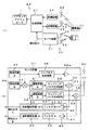
まず、第1形態例を説明する。本形態例は、車両の例えば運転席ドアのパッシブエントリーシステムの制御装置に本発明を適用した例である。このシステムは、図1(a)に示すように、携帯機10と、車両に搭載される本体機20及び検知装置30とよりなる。
携帯機10は、図示省略しているが、例えば100〜150kHz程度の低周波(LF)の起動信号を受信するためのアンテナや受信回路と、高周波(例えばUHFバンド内の周波数)で後述するアンサー信号や操作信号(施錠操作信号又は開錠操作信号)を無線送信するための送信回路及びアンテナと、少なくとも認証コード(IDコードなどとも呼ばれる)を記憶する携帯機側記憶手段(例えば、EEPROM)と、携帯機全体の制御や必要な情報処理を行うマイコンを含む制御回路と、内蔵電池とを備える。
なお、ここでいう起動信号は、携帯機10のマイコンをWAITモード(電力消費を押さえるための低消費電力モード、スリープ状態ともいう)から起動させる信号である。この場合、携帯機10のマイコンは、この起動信号により起動すると上記認証コードを含むアンサー信号(携帯機アンサー信号)を高周波の電波に載せて無線送信するようプログラムされており、この意味において上記起動信号は本発明のリクエスト信号に相当する。
またこの場合、携帯機10に必要な電力(少なくとも起動時の電力)は、本体機からの電力伝送でまかなうようにしてもよい。この場合、本体機20から携帯機10への送信周波数が低周波なので、この電波を使って電力伝送が比較的効率よく可能であり、携帯機10で必要な電力を全て本体機からの電力伝送でまかなうことも原理的には可能であり、そうすれば携帯機の内蔵電池が不要になる。
【0025】
また、携帯機10の表面には、押しボタン式の操作部である施錠用スイッチや開錠用スイッチ(図示省略)が設けられており、通常のキーレスエントリーシステム(単方向通信式のもの)としての遠隔操作が可能な構成となっていてもよい。即ち携帯機10は、上述した起動信号を受けて起動して前記アンサー信号を所定回数送信する機能を有するとともに、上記施錠用スイッチ又は開錠用スイッチが操作されると起動して、認証コードを含む施錠操作信号、或いは認証コードを含む開錠操作信号を無線送信する機能を有していてもよい。そして、これら施錠操作信号又は開錠操作信号が送信され、これらが本体機20で受信されると、本体機20の制御機能で照合確認がなされた上で車両のドアを即座に施錠又は開錠する動作が実行される構成となっていてもよい。
なお、本例の携帯機10は、必要な動作(例えば、上記アンサー信号の送信)を終了するとWAITモードに自動復帰し、その後に起動信号の受信等があるまでWAITモードを継続して電力消費を抑制する態様であるが、必ずしもこのような態様に限定されない。例えば携帯機10が、定常時はスタンバイモードとして待機し、所定タイミング毎に動作モードに移行して間欠的に受信回路を作動させて受信動作を間欠的に行う。そして、この間欠的な受信動作のいずれかで本体機20から無線送信される所定のリクエスト信号(起動信号ではなく単にアンサー信号を要求する信号であって、低周波に限らず高周波信号でもよい)を受信すると、これに応答して携帯機側記憶手段に登録された認証コードを含むアンサー信号を所定回数無線送信する態様でもよい。
【0026】
一方、本体機20は、図1(a)に示すように、制御回路21と、送信回路22及び送信アンテナ23(本体機送信アンテナ)と、受信回路24及び受信アンテナ25(本体機受信アンテナ)とを備える。この場合の送信回路22及び送信アンテナ23は、前述した低周波数の起動信号を送信するためのものであり、受信回路24及び受信アンテナ25は前述した高周波のアンサー信号や操作信号を受信するためのものである。制御回路21は、本体機全体の制御や車両のドアロックアクチュエータ1の制御に必要な処理を行うマイコンを含むものであり、この場合には、認証コードを記憶する本体機側記憶手段(例えば、EEPROM)を内蔵する。
なお、制御回路21、送信回路22、及び受信回路24は、例えば車両のドア内部等に配置される制御ユニット(ECU)内に設けられる。また、送信アンテナ23と受信アンテナ25は、上記制御ユニットに設けられてもよいが、送信回路22や受信回路24とともに、或いは送信回路22や受信回路24とは分離されて、上記制御ユニットとは別の位置(例えば、ルームミラー、ドアミラー、或いはドアハンドルなど)に設けられてもよい。
【0027】
次に、検知装置30について説明する。
この場合の検知装置30は、インパルスレーダの技術を利用して、車両のドアハンドルに接近した車両ユーザの身体(例えば手や指)を検出し、ドアの自動開錠動作や自動施錠動作のトリガとなる検知出力を生成するためのドアハンドルセンサであり、図1(b)に示す構成となっている。即ち、大きく分けてセンサ回路31と、送信アンテナ32と、受信アンテナ33とよりなる。
そしてセンサ回路31は、発振回路A(送信クロック生成回路)34と、インパルス生成回路35と、送信アンプ35aと、発振回路B(受信クロック生成回路)36と、ビート生成回路37と、検波回路部38,39と、判定回路部40,41とを有する。
なお、送信クロック生成回路34とインパルス生成回路35と送信アンプ35aは、本発明の送信波出力手段を構成する。また、受信クロック生成回路36とビート生成回路37は、本発明の検波信号を生成する要素である。また、検波回路部38,39は、本発明の検波手段に相当する要素である。また、判定回路部40,41は、本発明の判定手段に相当する。
また、センサ回路31は、制御回路21などとともに前述の制御ユニット内に設けてもよいが、送信アンテナ32や受信アンテナ33とともに、或いはこれらと分離させてドア又はドアハンドル内に収納することも可能である。
また、送信アンテナ32及び受信アンテナ33は、例えばドアハンドル形状に合わせた単純バー型であり、ドアハンドル若しくはドアの内面に並列若しくは分離して埋め込んだ状態(或いは張り付けた状態)で設けられている。なお、これらアンテナの構成(形状、配置、製法など)については、各種の態様があり得るが、それについては説明を省略する。
【0028】
ここで、送信クロック生成回路34は、インパルスレーダの基準波(例えば、455kHz)を生成する回路であり、例えば水晶振動子を発振源とする発振回路によって構成されている。また、受信クロック生成回路36は、インパルスレーダのビート波(例えば、1kHz)を生成する回路であり、例えば変形コルピッツ型低消費電流発振器によって、送信クロック生成回路34とは別個に構成されている。
なお、地雷探知装置等に使用されている従来のインパルスレーダは、基準波の生成回路の出力を多数回分周する分周回路を設けることによって、基準波からビート波を生成していたが、この場合分周回路で多くの電流を消費することになるので、従来のインパルスレーダを物体検知装置30としてそのまま車両へ適用することは困難である(車両のバッテリあがりの恐れがある)。しかし、本例のように低消費電流タイプの別個の発振回路によってビート波を生成するようにすれば、このような問題を解消できる。
【0029】
次に、インパルス生成回路35は、送信クロック生成回路34で生成された波形を整形し、所定の矩形波(パルス)として送信アンプ35aを介して送信アンテナ32に入力する。これにより、送信アンテナ32が、周期的にオンオフされ、所定の送信タイミングで所定の電磁波(送信アンテナ32の帯域幅による制限を受けた周波数成分で、高調波を含む)が放射される。
また、ビート生成回路37は、基準波にビート波を混合し、基準波の波形をビート波によって変化させたサンプリングパルス(ビート波に対応したゆらぎ成分を有するもの)を生成する回路である。
なお、サンプリングパルスにビート波に対応したゆらぎ成分を付加する技術は、インパルスレーダにおいて適正な反射波を効率よく受信するための一つの手法である。
【0030】
次に、検波回路部38は、遅延回路A51とサンプリングパルス生成回路52とサンプルホールド回路53とを有し、検波回路部39は、遅延回路B54とサンプリングパルス生成回路55とサンプルホールド回路56とを有する。
遅延回路A51は、前述した送信波の送信タイミングに対するサンプリングタイミングとして、図2(a)に示す比較的広い検知エリアAを実現するサンプリングタイミングAを設定するもので、一方、遅延回路B54は、図2(a)に示す比較的狭い検知エリアBを実現するサンプリングタイミングB(検知距離が短い分だけサンプリングタイミングAよりも早いタイミング)を設定するものである。ここで、検知エリアBは、例えばドアハンドル内側に設定されており、ドアハンドル内側に手が挿入又は接触されたときにオンする検知エリアに設定されている。このように検知エリアが設定されていると、寄りかかり等によって検知エリアAでの検知出力(後述する検知出力A)がオンしても、検知エリアBの検知出力(後述する検知出力B)がオフの状態を維持できるので、後述する如く寄りかかり対策が可能となる。
また、サンプリングパルス生成回路52は、ビート生成回路37で生成され、遅延回路A51を介して入力された波形を整形し、検波信号としてサンプルホールド回路53に入力する。そして、サンプルホールド回路53では、所定のサンプリングタイミングAで、受信アンテナ33からの入力にサンプリングパルス整形回路52の出力が混合され、受信アンテナ33からの入力のうちの所定の低周波成分(対象物の動きに起因する反射波の信号成分を含むもの)が取り出されて出力される。
一方、サンプリングパルス整形回路55は、ビート生成回路37で生成され、遅延回路B54を介して入力されたサンプリングパルスの波形を整形し、サンプルホールド回路56に入力する。そして、サンプルホールド回路56では、所定のサンプリングタイミングBで、受信アンテナ33からの入力にサンプリングパルス整形回路55の出力(本発明の検波信号)が混合され、受信アンテナ33からの入力のうちの所定の低周波成分(対象物の動きに起因する反射波の信号成分を含むもの)が取り出されて出力される。
【0031】
次に、判定回路部40は、図1(b)に示すように、低域増幅回路61と、バンドパスフィルタ(BPF)62と、波形整形回路63とよりなる。
ここで、低域増幅回路61は、サンプルホールド回路53の出力を扱い易いレベルに増幅するアンプであり、原理的には必ずしも必須な要素ではない。
また、バンドパスフィルタ62は、低域増幅回路61の出力のうち、検知しようとする対象物(この場合、人の手)の移動速度範囲に対応する周波数範囲(この場合、1Hz〜数10Hz)内にある信号成分のみを出力するフィルタ回路である。
波形整形回路63は、バンドパスフィルタ62の出力の振幅レベルを、この場合人の手の物性(主に誘電率)に対応した所定範囲の下限に相当するしきい値と比較し、このしきい値に対して前記振幅レベルが前記所定範囲側にあると(即ちこの場合には、しきい値を超えていると)、その出力(検知出力A)をオンにする回路である。
また判定回路部41は、図1(b)に示すように、判定回路部40と同様にサンプルホールド回路56の出力を処理して検知出力Bをオンにするものであり、低域増幅回路64と、バンドパスフィルタ(BPF)65と、波形整形回路66とよりなる。
【0032】
以上説明した検知装置30では、この検知装置30(少なくとも、アンテナ32,33)が設置された箇所(この場合、ドアハンドル)に対して、検知しようとする対象物(人の手)が検知エリアAの内側の距離まで接近すると、低域増幅回路61の出力特性値(周波数と振幅レベル)が、バンドパスフィルタ62と波形整形回路63の特性範囲に入り、波形整形回路63の出力(検知出力A)がオンになる。そして、対象物(人の手)が検知エリアBの内側の距離まで接近すると、低域増幅回路64の出力特性値(周波数と振幅レベル)が、バンドパスフィルタ65と波形整形回路66の特性範囲に入り、波形整形回路66の出力(検知出力B)がオンになる。
なお、対象物(人の手)が検知エリアA内に接近したが、検知エリアB外にある時には、検波手段39のサンプリングタイミングBが反射波の受信タイミングと合わないために、低域増幅回路64の出力特性値が前記特性範囲に入らず、波形整形回路66の出力(検知出力B)はオフのままとなる。また、対象物(人の手)が検知エリアB内の所定距離まで接近した時には、検波手段38のサンプリングタイミングAが反射波の受信タイミングと合わなくなるため、低域増幅回路61の出力特性値が前記特性範囲に入らなくなり、波形整形回路63の出力(検知出力A)はオフとなる。
【0033】
したがって、上記検知装置30が設置されたドアハンドルにユーザが手を接近させ、このドアハンドルをユーザが把持するまでの過程では、例えば図2(b)に示すように検知出力の状態が変化する。即ち、検知出力Aがオンとなった後、相応の時間経過後に検知出力Bがオンする。
ところが、例えば近くに携帯電話が存在するなど、上記検知出力をオンさせる強い外乱ノイズがある場合には、上述したような検知エリアの違いが問題にならなくなり、例えば図2(c)に示すように各検知出力の状態がほぼ同時に変化する可能性が高い。即ち、検知出力Aと検知出力Bがほぼ同時にオンする可能性が高い。
【0034】
なお、前述した振幅レベルは、受信波(反射波)の受信強度に相当するパラメータであり、アンテナからの距離の違いを無視すれば主に接近した物体の誘電率に応じて増減する。このため、対象物と誘電率の違う異物による波形成分は、周波数(即ち異物の接近速度)が対象物と仮に同程度だとしても、前記しきい値を下回って判定領域に入らず検知されない。この場合、例えば水や紙或いはプラスチックなどは、人の手よりも格段に誘電率が低いので、上記波形整形回路63の処理によって信頼性高く排除できる。即ち、例えば紙切れや枯葉などが、人の手の移動と同程度の速度でアンテナ32,33に接近したとしても、検知出力がオンとなる誤検知は発生しない。
また、低域増幅回路61の出力特性値のうちの周波数(移動する対象物の反射による成分の周波数)は、既述したように接近した物体の移動速度に対応する。このため、対象物と移動速度の違う異物による波形成分は、振幅レベル(即ち異物の誘電率)が対象物と仮に同程度だとしても、バンドパスフィルタ62,65の特性範囲から外れて検知されない。この場合、例えば人の手よりも早く移動する落下物や、極端にゆっくり移動する物体(停止物含む)は、人の手と同程度の誘電率をもつ物体(例えば、金属)だとしても、上記バンドパスフィルタ62,65の作用によって信頼性高く排除できる。例えば、金属製の柱などにアンテナ32,33が接近した状態で車両が駐車されたときでも、その金属製の柱が手と誤って検知され続けることはない。また、万が一誘電率の高い雨滴などが落下してきたとしても、高い確率で誤検知を回避できる。
【0035】
したがって、この場合の検知装置30によれば、人の手が接近したときには確実に検知出力がオンとなり、その他の異物の接近などによっては、ほとんどの場合誤検知又は誤動作が生じない(少なくとも、誤検知や誤動作が繰り返し継続するような不具合は、信頼性高く回避される)。
また、人の手が通常の速度で接近した正常時には、前述したように検知出力AとBが相応の時間をおいて順にオンし、外乱ノイズなどによって異常に検知出力がオンする場合には、検知出力AとBがほぼ同時にオンする。このため、このような検知動作の違いに応じて検知結果を修正する検知出力修正手段(例えば、各検知出力が規定時間以内の同時期にオンすると、検知出力AとBを何れもオフに反転させて制御回路21に入力する回路)を設けることによって、外乱ノイズなどによる誤検知(ひいてはシステムの誤動作)も防止することができる。なお、上記検知出力修正手段は、例えば後述するような制御回路21の処理機能によって実現することもできる(後述のステップS2参照)。本例では、制御回路21の処理によって上記検知出力修正手段が実現されている場合を説明する。
【0036】
次に、制御回路21の機能、及び本システムの動作について説明する。
上記制御回路21は、例えば以下のような処理動作を実行する機能を有する。即ち基本的には、車両のドアが施錠状態にある場合(ドアロックアクチュエータ1が作動状態の場合)には、検知装置30の検知出力Aがオンになると、送信回路22及び送信アンテナ23により前述の起動信号を所定回数送信するとともに、受信回路24を機能させて受信動作を実行する。そして、起動信号の送信後に携帯機10からアンサー信号を受信すると、このアンサー信号に含まれる認証コードが本体機側記憶手段に予め登録された認証コードに対応しているか否かを判定し、この判定結果が肯定的であれば、さらに検知出力Bがオンになったことを条件として、ドアロックアクチュエータ1を制御し、施錠状態にある車両のドアを開錠する。
また、本例の制御回路21は、車両のドアが開錠状態にある場合に、検知装置30の検知出力Bがオンになると、やはり起動信号を送信するとともにアンサー信号を受信し、認証コードの照合確認がなされたことを条件として、ドアロックアクチュエータ1を制御し、開錠状態にある車両のドアを施錠する。
【0037】
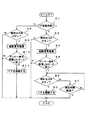
なお図3は、制御回路21の上述した制御処理を実現するフローチャートの一例である。この場合、制御回路21は、図3に示す処理を例えば周期的に実行する。
まずステップS1では、ドアが施錠状態か否か判定し、施錠状態でなければ(即ち、開錠状態であれば)ステップS8に進む。施錠状態の場合には、ステップS2で、検知エリアA内で手が検知されたか否か(即ち、検知装置30の検知出力Aがオンになっているか否か)を判定する。そして、検知されていない場合には、1シーケンスの処理を終了し、検知されている場合には、ステップS3に進む。但し、このステップS2では、同時に検知出力Bの状態も確認し、検知出力AとBが規定時間以内の同時期にオンになっている場合には、判定結果を否定的として、1シーケンスの処理を終了する。なお、1シーケンスの処理を終了すると、次の実行タイミングでステップS1から処理を繰り返す。
【0038】
そしてステップS3では、送信回路22を制御して前記起動信号を所定回数送信する。
次にステップS4では、アンサー信号を受信しこのアンサー信号に含まれる認証コードの照合確認が適正に行われたか否かを判定する。照合結果が適正であれば、ステップS5に進む。
次いでステップS5では、ステップS2で検知出力Aがオンになった後に、検知エリアB内で手が検知されたか否か(即ち、検知装置30の検知出力Bがオンになっているか否か)を判定し、検知されている場合にはステップS6に進み、検知されていない場合にはステップS7に進む。
そして、ステップS6では、ドアロックアクチュエータ1を制御してドアを開錠する。また、ステップS7では、検知出力Aがオンになった時点からの経過時間が規定時間に到達したか否か判定し、規定時間に到達していれば、1シーケンスの処理を終了する。なお、規定時間に到達していなければ、ステップS5に戻って処理を繰り返す。
【0039】
一方、ステップS8では、検知エリアB内で手が検知されたか否かを判定し、検知されている場合にはステップS9に進み、検知されていない場合には、1シーケンスの処理を終了する。
そして、ステップS9では、ステップS3と同様に前記起動信号を送信し、次のステップS10では、ステップS4と同様にアンサー信号の受信及びその照合確認を行う。そして、照合結果が適正であれば、ステップS11に進み、ドアロックアクチュエータ1を制御してドアを施錠する。
なお、ステップS4,S10で、判定結果が否定的の場合にも、1シーケンスの処理を終了する。
【0040】
以上説明した本形態例の検知装置30及びこれを利用した錠制御装置では、次のような効果が得られる。
(1)インパルスレーダの技術を利用してドアハンドルに接近した手を非接触で検知するため、汚れによって誤検知が起こる恐れがなく、また異物(例えば、雨や枯葉など)の存在によって誤検知が起こる可能性も、従来の光学式センサ等に比較して格段に少ない。特に本装置では、反射波の受信強度(振幅レベル)と周波数の両方に基づいて、人の手を他の異物と識別して検知しているので、手以外の異物を誤検知する可能性が極めて低い。このため、誤検知によって不必要に装置が動作してしまう不具合(この場合、前記起動信号が不必要に送信され、車両のバッテリが無駄に消耗するなどの不具合)の発生可能性を格段に低減できる。
(2)送信出力、受信感度、及びサンプリングタイミングなどの設定により、検知エリアを十分広く(検知距離を十分長く)適度な大きさに設定できるので、十分な応答性を得ることが容易である。この場合、ドアハンドルに接触する位置よりも十分前の位置でユーザの手を検知できるので、ユーザがドアを開けようとドアハンドルを引き始めたときには、施錠状態にあった車両ドアが確実に自動開錠されており、パッシブエントリーシステムの利便性が十分発揮される。
特に本例では、複数ある検知エリアのうち、最小でない特定の検知エリア(この場合、広い検知エリアA)に対応する検知出力(検知出力A)がオンになった時に、前記起動信号(リクエスト信号)を送信して携帯機10との通信を開始し、その後に開錠条件(携帯機10のIDコードの照合確認等)の成立を確認した上で、自動開錠動作を行う構成となっている(前述のステップS2〜S6参照)。即ち、複数ある検知エリアのうち、より大きな検知エリアで対象物である手が検知されたときに、すぐに携帯機10を起動させて携帯機10との通信を開始するため、ユーザの手がドアハンドルに接触するまでには、時間のかかる携帯機10との通信や照合確認処理を確実に完了させ、自動開錠動作を実行することが可能であり、応答性が良い。
【0041】
(3)電波式レーダを利用しているので、物体の接近を検知しようとする所定部位(この場合、車両のドアハンドル)に必ずしも検知装置30の全要素(この場合、センサ回路31など)を設ける必要がない。即ち、少なくともアンテナ32,33を所定部位(ドアハンドル)又はその近傍に設置すればよい。また本装置では、反射波信号の周波数と振幅レベルによって検知判定を行い、判定処理にマイコンを使用しない構成であるため、センサ回路31の構成が格段に簡素かつ小型になっており、センサ回路31を含めた検知装置30全体をドアハンドルに内蔵させることも比較的容易である。このため、所定部位であるドアハンドル(或いはその近傍)の形状や大きさを変更する必要性が少なく、そのデザインの自由度も大きく制限されない。
【0042】
(4)検知装置30は、上述したように判定処理にマイコンを使用しない構成である。具体的には、バンドパスフィルタなどよりなる簡素な判定回路部40,41における簡単な処理によって、検知判定が信頼性高く行われる。このため、マイコンによる複雑な波形分析や判定処理を行う従来のインパルスレーダよりも消費電力が格段に少なくなり、パッシブエントリーシステムのトリガ生成用として問題なく車両に搭載することができる(車両のバッテリ上がりの問題が解消できる)。特に本形態例の場合には、インパルスレーダの送信クロック生成回路34と受信クロック生成回路36を、別個の発振回路により構成しており、ビート波生成のために基準波を多段階に分周する処理が不要となっている。このため、この点でも電力が節約されており、検知装置30の消費電力が特に小さくなっている。
(5)検知装置30が大きさの異なる複数の検知エリア(この場合、二つの検知エリアA,B)を有し、各検知エリア毎に対象物の接近を検知して各検知出力(検知出力A,B)をそれぞれオンとする構成であり、各検知エリアに対する検知出力A,Bの両方が同時期にオンすると、検知結果を否定的とする検知出力修正手段(この場合、制御回路21の前述のステップS2における処理機能)が設けられている。このため、既述したように、強い外乱ノイズなどによる誤動作を、相当の信頼性で回避することができる。
【0043】
(6)複数ある検知エリアのうち、特定の検知エリア(この場合、検知エリアA)に対応する検知出力(検知出力A)がオンになった後、前記特定の検知エリアよりも小さい検知エリア(検知エリアB)に対応する検知出力(検知出力B)が順番にオンになることが、自動開錠動作の条件(開錠条件)として含まれている(前述のステップS2及びS5参照)。このため、応答性を高めるべく特定の検知エリアAを十分広く設定したとしても、寄りかかり等による不正常な検知出力と区別して、ドアを開けようとするユーザの手の接近のみを、より確実に判定して自動開錠動作を的確に行うことができる。
【0044】
(7)検知装置30が大きさの異なる二つの検知エリアA,Bを有し、ドアの自動開錠動作のトリガとしては応答性の良い広い検知エリアAが使用され(前述のステップS2)、ドアの自動施錠動作のトリガとしては信頼性の高い狭い検知エリアBが使用されている(前述のステップS8)。このため、システムの状態に応じた最適な検知エリアの大きさとすることができる。
(8)上述したように、検知装置30を自動施錠動作のトリガとしても良好に機能させることができるので、従来のようなユーザが操作するスイッチを設ける必要がなくなり、この点でもデザインの自由度が高まるとともに、ユーザのスイッチ操作が不要となって操作性が良くなる。
(9)また、本例の検知装置30は、異なるサンプリングタイミングをもつ検波手段(検波回路部38,39)と、これに対応する判定手段(判定回路部40,41)だけを複数(この場合、二つ)設けることによって、アンテナや発振回路などの要素を複数設けることなく、複数の検知エリアを実現している。このため、単純に電波式センサを複数設ける構成に比べて、小型で簡素、かつ消費電力の少ないものとなっている。したがって、既述した効果(消費電力の低減、デザインの自由度向上など)を十分高く発揮できる。
【0045】
(第2形態例)
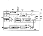
次に、図4及び図5により、第2形態例を説明する。本形態例は、第1形態例の変形であり、検波手段や判定手段を一組の回路で構成したものである。なお、第1形態例と同様の要素には同符号を使用して、重複する説明を省略する。
本例の検知装置30は、図4に示すように、一つの検波回路部38aと、これに対する一つの判定回路部40とを備える。
検波回路部38aは、遅延回路51aとサンプリングパルス生成回路52とサンプルホールド回路53とを有する。
【0046】
ここで、遅延回路51aは、前述した送信波の送信タイミングに対するサンプリングタイミングとして、制御回路21からの入力信号で指定されたサンプリングタイミング(前述の検知エリアAを実現するサンプリングタイミングAと、検知エリアBを実現するサンプリングタイミングBの何れか一方)を設定するものである。
本例の検知装置30では、遅延回路51aによりサンプリングタイミングAが設定されている状態で、検知しようとする対象物(人の手)が検知エリアAの内側の距離まで接近すると、判定回路部40の検知出力がオンになる。
また、遅延回路51aによりサンプリングタイミングBが設定されている状態で、対象物(人の手)が検知エリアBの内側の距離まで接近すると、判定回路部40の検知出力がオンになる。
【0047】
次に、本形態例における制御回路21の機能、及びシステムの動作について説明する。
この場合、制御回路21は、例えば以下のような処理動作を実行する機能を有する。即ち基本的には、車両のドアが施錠状態にある場合(ドアロックアクチュエータ1が作動状態の場合)には、サンプリングタイミングAを設定し、この状態で検知装置30の検知出力がオンになると、送信回路22及び送信アンテナ23により前述の起動信号を所定回数送信するとともに、受信回路24を機能させて受信動作を実行する。そして、起動信号の送信後に携帯機10からアンサー信号を受信すると、このアンサー信号に含まれる認証コードが本体機側記憶手段に予め登録された認証コードに対応しているか否かを判定し、この判定結果が肯定的であれば、さらにサンプリングタイミングBでの検知出力がオンになったことを条件として、ドアロックアクチュエータ1を制御し、施錠状態にある車両のドアを開錠する。
また、車両のドアが開錠状態にある場合には、サンプリングタイミングBを設定し、この状態で検知装置30の検知出力がオンになると、やはり起動信号を送信するとともにアンサー信号を受信し、認証コードの照合確認がなされたことを条件として、ドアロックアクチュエータ1を制御し、開錠状態にある車両のドアを施錠する制御を実行する。
【0048】
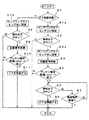
なお図5は、制御回路21の上述した制御処理を実現するフローチャートの一例である。この場合、制御回路21は、図5に示す処理を例えば周期的に実行する。なお、図3の処理と同様のステップには同符号を付し、場合により説明を省略する。
まず、ステップS1の判定で、施錠状態でなければステップS1bに進み、施錠状態の場合にはステップS1aに進む。
そしてステップS1aでは、サンプリングタイミングAが設定されていない場合、遅延回路51aへの入力信号を切り替えてサンプリングタイミングAを設定する。
ステップS1aを経ると、ステップS2で、検知エリア内で手が検知されたか否か(即ち、検知装置30の検知出力がオンになっているか否か)を判定する。そして、検知されていない場合には、1シーケンスの処理を終了し、検知されている場合には、ステップS2aに進む。
次にステップS2aでは、遅延回路51aへの入力信号を切り替えてサンプリングタイミングBを設定する。
なお、このステップS2aの次に、ステップS2と同様に検知出力を判定し、検知出力がオンになっている場合には、1シーケンスの処理を終了するステップを設けてもよい。このようにすると、検知エリアAでの手の検知の直後に検知エリアBでも手が検知されたこと(即ち、複数の検知エリアの検知出力が同時期にオンになり、誤検知であると推定されること)を判定して、不正常な自動開錠動作を中止できる(即ち、外乱ノイズなどによる誤動作を回避できる)。
【0049】
そしてステップS2aを経ると、ステップS3,S4で、起動信号を送信し、アンサー信号を受信し、このアンサー信号に含まれる認証コードの照合確認を行い、照合結果が適正であれば、ステップS5に進む。
次いでステップS5では、検知エリアA内で手が検知された後に、検知エリアB内で手が検知されたか否か(即ち、検知装置30の検知出力がオンになっているか否か)を判定し、検知されている場合にはステップS6に進んでドアを開錠し、検知されていない場合にはステップS7に進む。
一方、ステップS1bでは、サンプリングタイミングBが設定されていない場合、遅延回路51aへの入力信号を切り替えてサンプリングタイミングBを設定する。
ステップS1bを経ると、ステップS8で、検知エリアBで手が検知されたか否かを判定し、検知されている場合にはステップS9に進み、検知されていない場合には、1シーケンスの処理を終了する。
【0050】
そして、ステップS9では、ステップS3と同様に前記起動信号を送信し、次のステップS10では、ステップS4と同様にアンサー信号の受信及びその照合確認を行う。そして、照合結果が適正であれば、ステップS11に進み、ドアロックアクチュエータ1を制御してドアを施錠する。
以上説明した本形態例によれば、第1形態例と同様の効果に加え、次のような効果がある。即ち、検波手段と判定手段が一組の回路(検波回路部38a、判定回路部40)によって実現されるため、さらなる小型化、簡素化及び省エネが可能となる。
【0051】
なお、本発明は上記形態例に限定されるものでなく、各種の変形や態様があり得る。
例えば、上記実施の形態では車両ドアの開錠動作等についてしか具体例を挙げなかったが、本発明は車両ドアの開錠等に限られず、各種の制御対象や制御内容があり得る。例えば、本発明の検知装置により、車両におけるトランクの開閉用ハンドルに接近するユーザの手を検知するようにして、トランクの自動開錠又は自動施錠等にも適用できる。また、車両以外でも、例えば船舶や小型飛行機などの乗物や、或いは建物のドアの自動開錠等にも応用できる。
また前記実施の形態では、人の手を検知する場合を例示したが、判定手段の特性(例えば、バンドパスフィルタなどの特性)を変更することで、人の手以外の物体(例えば、雨粒)を対象物として他の物と識別して検知することも可能である。
【0052】
また上記形態例では、狭い検知エリアBでの1回の検知出力(検知出力Bの1回のオン)を、自動施錠動作のトリガとしているが、これに限られない。例えば図6(a)に示すように、検知出力Aだけが1回オンすると、これをトリガとして自動施錠動作を実行するようにしてもよい。或いは、例えば図6(b)に示すように、規定時間内に検知出力Aだけが2回オンすると(即ち、ユーザが検知エリアA内に手を出したり引っ込めたりする動作を2回実行すると)、これをトリガとして自動施錠動作が実行される構成としてもよい。
また、検知装置や本体機の各アンテナは、金属或いは導電性樹脂等によって取付部位と別部品として製作し、圧入やネジ止め等によって取付部位(例えば、ドアハンドル又はドアの内部或いは表面)に固定してもよいが、例えば樹脂製のドアハンドルやドアにインサート成形してもよい。また、例えば樹脂製のドアハンドルやドアに、いわゆる2色成型によって導電性樹脂よりなるアンテナを作り込んでもよい。また、樹脂上にメッキすることによって、上記アンテナを形成してもよい。
【0053】
また、本発明のリクエスト信号は、携帯機等をスリープ状態(マイコンのWAIT状態)から起動させる起動信号に限らず、すでに起動状態(マイコンの待機状態含む)にある携帯機に対して、単に所定のアンサー信号の送信を要求する信号であってもよい。また、このリクエスト信号の無線周波数は、LF帯に限らず、その以外の帯域(例えば、UHF帯)であってもよい。但しLF帯は、電波の回り込みが少ないという点で有利であり、電力伝送も比較的効率よく行える。
また、リクエスト信号には、なんらかの固有コード(防犯性の観点から開錠等のための認証コードでないことが好ましい)を含ませてもよい。例えば、車両のエントリーシステムでは、同種のエントリーシステムを搭載した他の車両が近くに複数台存在しているような状況で使われることが十分あり得るため、このような状況で他車の本体機から送出されたリクエスト信号を携帯機が受信し、その都度認証コードを含むアンサー信号を携帯機が送信しないように、他車との識別のために携帯機においても上記固有コードの照合確認を行った上でアンサー信号を返信するようにしてもよい。
また、使用する周波数帯等の違いに問題がなければ、本体機のアンテナと、検知装置のアンテナを、共通のアンテナにより構成することができる。
【0054】
【発明の効果】
本発明によれば、電波式レーダの技術を利用し、動作信頼性や応答性、ユーザの操作性、さらには車両などへの搭載性(大きさやデザイン或いは消費電力などの面での優位性)の点で優れた検知装置、及びこれを利用した優れた錠制御装置(パッシブエントリーシステムの制御装置)を提供することができる。
【図面の簡単な説明】
【図1】錠制御装置及び検知装置の構成を示す図である。
【図2】検知装置の検知エリアや動作を説明する図である。
【図3】錠制御装置の制御内容を示すフローチャートである。
【図4】検知装置(第2形態例)の構成を示す図である。
【図5】錠制御装置の制御内容(第2形態例)を示すフローチャートである。
【図6】他の形態例の動作を説明する図である。
【符号の説明】
10 携帯機
20 本体機
21 制御回路
30 検知装置
32 送信アンテナ
33 受信アンテナ
34 発振回路A(送信波出力手段)
35 インパルス生成回路(送信波出力手段)
35a 送信アンプ(送信波出力手段)
36 発振回路B
37 ビート生成回路
38,38a,39 検波回路部(検波手段)
40,41 判定回路部(判定手段)[0001]
BACKGROUND OF THE INVENTION
The present invention is a detection device suitable for applications such as detecting the approach of a vehicle user's hand trying to operate a door handle in order to generate a trigger (trigger) for an automatic unlocking operation of a passive entry system of a vehicle, for example. And a lock control device using the same.
[0002]
[Prior art]
In recent years, in vehicle entry systems, etc., two-way communication is carried out between a portable device carried by a vehicle user and a main body mounted on the vehicle, and after confirming necessary verification, automatic operation of the vehicle equipment is performed. A device to be realized has been proposed and partially put into practical use.
In such a bidirectional communication type, an answer signal including a necessary code for a request signal transmitted from the main unit (for example, an activation signal for starting the portable unit) is automatically transmitted from the portable unit to the main unit. Since it becomes possible to transmit, predetermined | prescribed operation | movement of vehicle equipment is realizable even if a user does not operate at all. For example, in a vehicle entry system, a user who carries a portable device only approaches the door of a specific vehicle equipped with the corresponding main unit, and the door lock is locked when the bidirectional communication is established. An unlock command is automatically output to the device, and the vehicle door can be automatically unlocked. In addition, a more convenient entry system that realizes the unlocking or locking operation of the vehicle door without requiring the user's conscious operation basically as an advanced type of a general keyless entry system, This is called a passive entry system (or smart entry system), and market needs are increasing as it increases the commercial value of vehicles.
[0003]
By the way, in such a passive entry system, if a request signal from the main unit is transmitted as much as possible to save battery power of the vehicle, the vehicle user approaches the vehicle (for example, the door handle portion). Alternatively, it is necessary to provide a detection device that detects contact.
However, conventionally, as such a detection device, an optical or capacitance sensor or the like has been used. In addition, for example, a push button type switch operated by a user is provided on the door handle or the vicinity thereof in order to generate a trigger for an automatic locking operation when getting off.
[0004]
Here, in the optical sensor, the output change of the light receiving element caused by the light output from the light emitting element being blocked by the hand of the vehicle user, for example, or the light output from the light emitting element is reflected by the hand of the vehicle user, for example. Based on the change in the output of the light receiving element caused by the reflected light entering the light receiving element, for example, the approach of the vehicle user's hand to the door handle is detected.
Further, the capacitive sensor is a so-called touch sensor, for example, as disclosed in
In addition, as a non-contact type short-range sensor, as disclosed in
[0005]
[Patent Document 1]
JP 2002-295064 A
[Patent Document 2]
International Publication No. 00/023762
[0006]
[Problems to be solved by the invention]
However, the conventional technique in which the above-described detection device and switch are provided has the following problems.
(B) In the case of an optical sensor, there is a risk of malfunction due to the presence of dirt or foreign matter (for example, rain or dead leaves).
(B) In the case of an optical or capacitive sensor, since the detection area is narrow (the detection distance is short), it is difficult to obtain sufficient responsiveness, and there is a risk of malfunction in the operation of the application system. . For example, in order to obtain a trigger for request signal transmission in a vehicle passive entry system, when the sensor is provided on the handle of a vehicle door, it is not detected unless the user's hand is close enough to touch the sensor (ie, the request signal Is not output, but the user has started to pull the door handle to open the door, but the automatic unlocking has not yet been performed, and the door does not open immediately (ie, locked using the passive entry system) Even if an attempt is made to open the door in a state, there is a possibility that the door will not be opened immediately after the operation until automatic unlocking is delayed, and the user may feel a catching response).
[0007]
(C) Since it is necessary to provide a relatively large sensor element that is difficult to incorporate in a part (for example, a vehicle door handle) that is to detect the approach of an object, The size needs to be changed considerably, and the degree of freedom in designing the part is greatly limited.
(D) Also, when the trigger is generated in a passive entry system of a vehicle by a switch operated by a user, for example, the degree of freedom of design of a part to which the switch is attached (for example, a vehicle door or a door handle) is large. In addition to being limited, there is a problem in that the switch operation of the user is necessary, which is inconvenient and the operability is not good.
[0008]
In addition, as a non-contact type short-range sensor that can set a large detection area and is not affected by dirt or the like, a radio wave sensor such as the impulse radar described above is known, and the inventors have used this radio wave sensor. Was applied to the above-mentioned detection device.
However, even if the radio wave sensor is used, there are the following problems.
(E) Since it is difficult to define the detection area, if the detection area is enlarged to solve the above-mentioned problem (b), there is a possibility that a trigger will occur regardless of the user's intention due to leaning on the door handle. There is a risk of malfunction due to strong disturbance noise (for example, radio waves from a mobile phone).
(F) The conventional radio wave sensor has only one setting for the size of the detection area. For this reason, it has been impossible to obtain an optimal detection area size according to the state of the system to be applied. For example, as a trigger for automatic unlocking operation in a vehicle passive entry system, it is necessary to detect the approach of the user's hand (object) early in a relatively wide detection area in order to solve the problem (b) described above. However, as the trigger of the automatic locking operation in the system, since there is no problem (b) described above, it is desirable to reliably detect the approach of the user's hand without malfunction in a relatively narrow detection area. However, if there is only one setting for the detection area, it is impossible to use it properly. As a result, for example, it is necessary to install a switch as described above for generating a trigger for the automatic locking operation. D) The problem remains.
[0009]
Note that it is conceivable to set a plurality of detection areas by simply providing a plurality of radio wave sensors. However, in this case, for example, a plurality of transmission / reception antennas need to be installed at or near the door handle, the configuration becomes complicated, and the above-mentioned problem (c) cannot be solved sufficiently. In addition, in this case, there is a disadvantage that the power consumption of the detection device is increased by a factor of two or three compared to a case where one radio wave sensor is provided.
Therefore, the present invention uses radio wave radar technology to provide operational reliability, responsiveness, user operability, and mountability to vehicles, etc. (advantages in terms of size, design, power consumption, etc.) It is an object of the present invention to provide a detection device that is superior in terms of the above and a lock control device that uses the detection device.
[0010]
[Means for Solving the Problems]
The first detection device of the present application is a detection device that detects that an object has approached the detection area,
It has multiple detection areas with different sizes,
A transmission wave output means for outputting a transmission wave at a predetermined transmission timing, a transmission antenna that radiates the transmission wave output from the transmission wave output means to space as an electromagnetic wave, and a radiation emitted from the transmission antenna and reflected from an object A receiving antenna for receiving electromagnetic waves;A plurality of detection means provided for each of the detection areas of different sizes;Provided for each of these detection means, based on the output of each detection means, comprising a plurality of determination means for turning on the detection output indicating that the object has approached,
The detection means mixes a signal received by the receiving antenna with a detection signal corresponding to the transmission wave at a sampling timing for realizing the detection area, and outputs the mixed signal.It is characterized by this.
[0011]
Here, the “object” is, for example, a human hand. The detection device of the present application is mounted on an object having an opening / closing part such as a vehicle, and detects a vehicle user's hand approaching a handle (knob) of the opening / closing part (for example, a vehicle door or trunk) as an object. Suitable for applications (for example, trigger generation for passive entry systems in vehicles)
In addition, "determination means"For exampleAmong the output signals of the detection means, the amplitude level of the signal component within the frequency range corresponding to the speed range in which the object moves is a property that affects the physical properties (radio wave reflection characteristics) of the object. In this case, it is preferable to turn on the detection output when it is within a predetermined range mainly corresponding to the dielectric constant. Such a determination means includes, for example, a filter (for example, a bandpass filter) that outputs only a signal component within the frequency range of the output signal of the detection means, and the amplitude level of the output of the filter, Compared with a threshold value corresponding to a boundary of a predetermined range, a circuit that turns on a detection output when the amplitude level is on the predetermined range side with respect to the threshold value can be realized with a simple and small configuration. .
[0012]
According to this detection device, the following effects can be obtained.
(1) Since the approach of an object is detected in a non-contact manner using radio wave radar technology, there is no risk of false detection due to dirt, and false detection due to the presence of foreign matter (for example, rain or dead leaves). The possibility of occurrence is much less than that of a conventional optical sensor or the like.
(2) Since the detection area can be set to a sufficiently large size (with a sufficiently long detection distance) by setting the transmission output, reception sensitivity, sampling timing, etc., it is easy to obtain sufficient responsiveness.
[0013]
(3) Since the radio wave type radar is used, it is not always necessary to provide all elements of the detection device at a predetermined part (for example, a door handle of a vehicle) where an approach of an object is to be detected. That is, at least the antenna may be installed at or near a predetermined site. For this reason, there is little need to change the shape and size of a predetermined part (or the vicinity thereof), and the degree of freedom of design is not greatly limited.
(4) A configuration having a plurality of detection areas of different sizes, detecting the approach of the object for each detection area, and turning on each detection output. For this reason, abnormal detection output ON status due to disturbance noise, etc., is determined according to the status of each detection output (whether multiple are ON at the same time), preventing malfunction of the application system due to disturbance noise, etc. It becomes possible to do.
(5) Moreover, since it has several detection areas from which a magnitude | size differs, it becomes possible to set it as the optimal detection area magnitude | size according to the state of the system to apply.
(6) Further, this detection apparatus is provided with a plurality of detection means having different sampling timings and a plurality of determination means corresponding to the detection means, thereby providing a plurality of detection without providing a plurality of elements such as transmission wave output means and antennas. Realize the area. For this reason, compared with the structure which provides a plurality of radio wave type sensors simply, it can be small, simple, and consume less power. Therefore, effects such as reduction of power consumption and improvement of design freedom can be exhibited.
[0014]
next,As a preferable aspect of the first detection device of the present application, the plurality of determination means may be configured as described above.When the detection output is turned on at the same time, equipped with detection output correction means to make the detection result negativeIt is good also as an aspect.
With this configuration,The detection output correction means corrects an abnormal on-operation of the detection output due to disturbance noise or the like in the detection device, thereby preventing erroneous detection due to disturbance noise or the like (and thus a malfunction of the applied system).
[0015]
Also,Second of this applicationThe detection device is a detection device that detects that an object has approached the detection area, and
It has multiple detection areas with different sizes,
A transmission wave output means for outputting a transmission wave at a predetermined transmission timing, a transmission antenna that radiates the transmission wave output from the transmission wave output means to space as an electromagnetic wave, and a radiation emitted from the transmission antenna and reflected from an object A receiving antenna that receives electromagnetic waves, a detection means that mixes and outputs a detection signal corresponding to the transmission wave to a signal received by the receiving antenna at a specified sampling timing, and an object based on the output of the detection means Determining means for turning on detection output indicating that an object has approached;Control means for designating the sampling timing as sampling timing for realizing the plurality of detection areas.It is characterized by that.
[0016]
thisSecondIn the detection device, the size of the detection area is switched by switching the designation of the sampling timing of the detection means. Therefore, in effect, this detection device is alsoFirstSimilar to the detection device, it has a plurality of detection areas with different sizes, detects the approach of the object for each detection area, and turns on the detection output. Therefore, the same effects as the effects (1) to (5) of the first detection device described above can be obtained.
Moreover, this detection apparatus substantially realizes a plurality of detection areas without providing a plurality of all elements including the detection means and the determination means. For this reason, compared with the above-mentioned 1st detection apparatus, size reduction, simplification, or energy saving is implement | achieved.
[0017]
Next, the first lock control device of the present application is a control device such as a passive entry system equipped on an object having an opening / closing part (for example, a vehicle), and a user's hand approaching the handle of the opening / closing part is an object. As a means to detect as described aboveFirstA detection device is provided, and the detection output of the detection device is used as a trigger for system operation (automatic unlocking operation).
That is, the above-mentionedFirstA detection device and a main body provided on an object having an opening / closing portion, wherein the main body has a detection output corresponding to a specific detection area that is not a minimum of the detection device when the opening / closing portion is in a locked state. When turned on, the wireless communication device transmits a predetermined request signal to a portable device carried by the user, receives an answer signal from the portable device in response to the request signal, and at least includes that the received answer signal is proper. An unlocking control for unlocking the opening / closing part is executed after confirming the establishment of the locking condition.
[0018]
According to this lock control device, the aforementionedFirstThe detection device detects a hand approaching the handle with high reliability and responsiveness, and using this as a trigger, a request signal is transmitted from the main body equipped on the vehicle or the like to the portable device carried by the user, from the portable device. When the unlocking signal is transmitted to the main body and the unlocking condition is satisfied, an automatic unlocking operation (an operation for automatically unlocking an opening / closing part such as a locked door) is performed.
For this reason, the convenience of the system is fully demonstrated, and the malfunction that the system operates unnecessarily due to erroneous detection (occurrence of erroneous trigger) (request signal is transmitted unnecessarily, unlocking operation is not performed). The possibility of occurrence of a problem that the vehicle battery is unnecessarily exhausted if necessary is greatly reduced. In addition, there is little need to change the shape and size of the handle of the opening / closing part, and the degree of freedom of design is not greatly limited.
[0019]
The unlocking condition includes that the detection output corresponding to the detection area smaller than the specific detection area is turned on after the detection output corresponding to the specific detection area is turned on. It is good to be. In this mode, only when the detection output is turned on in order in a specific detection area and a smaller detection area (that is, it is ensured that the user's hand trying to open the door has normally approached the door handle). An automatic unlocking action is performed only when estimated). Therefore, even if a specific detection area is set to be sufficiently wide to improve responsiveness, it is more reliably determined only from the approach of the user's hand trying to open the door, as distinguished from abnormal detection output due to leaning or the like. Automatic unlocking operation can be performed accurately.
[0020]
In addition, when the detection output corresponding to a detection area smaller than a specific detection area of the detection device is turned on when the opening / closing unit is in the unlocked state, the main body unit is configured to perform a predetermined operation on a portable device carried by the user. The request signal is transmitted wirelessly, the answer signal from the portable device corresponding to the request signal is received, and after confirming that the received answer signal is appropriate, the locking control for locking the opening / closing unit is executed. It is desirable that the configuration be
In this way, the detection device can function well as a trigger for the automatic locking operation, so there is no need to provide a switch that is operated by the user as in the prior art, and this also increases the degree of freedom in design. This eliminates the need for a user's switch operation and improves operability. In this case, a relatively wide detection area (specific detection area) with good responsiveness is used as a trigger for the automatic unlocking operation of the door, and a highly reliable and relatively reliable trigger for the automatic locking operation of the door. A narrow detection area (a detection area smaller than a specific detection area) is used. For this reason, it becomes possible to make it the size of the optimal detection area according to the state of the system.
[0021]
Next, the second lock control device of the present applicationSecondA detection device and a main body provided on an object having the opening / closing portion, the main body,Having the function of specifying the sampling timing as the control means;When the opening / closing part is in the locked state, the sampling timing of the detection means is set so that the detection area becomes relatively large, and the user carries the detection output of the detection device in this state. After wirelessly transmitting a predetermined request signal to the portable device, receiving an answer signal from the portable device in response to the request signal, and confirming that the unlocking condition including at least that the received answer signal is proper is satisfied And performing unlocking control for unlocking the opening and closing unit,
In addition, when the opening / closing part is in the unlocked state, the sampling timing of the detection means is set so that the detection area becomes relatively small, and when the detection output of the detection device is turned on in this state, Wirelessly transmits a predetermined request signal to a portable device carried by the mobile device, receives an answer signal from the portable device in response to the request signal, and confirms that the received answer signal is appropriate, The locking control for locking is executed.
[0022]
In this second lock control device, the aforementionedSecondThe detection device detects a hand approaching the handle with high reliability and responsiveness, and using this as a trigger, a request signal is transmitted from the main body equipped on the vehicle or the like to the portable device carried by the user, from the portable device. When the answer signal is transmitted to the main unit, an automatic unlocking operation or an automatic locking operation is executed. Note that the automatic unlocking operation is premised on the establishment of the unlocking condition including at least the verification check of the answer signal. Further, in this case, a relatively wide detection area with good responsiveness is used as a trigger for the automatic unlocking operation of the door, and a relatively narrow detection area with high reliability is used as a trigger for the automatic door locking operation. .
For this reason, the same effect as the above-mentioned 1st lock control device can be acquired also by this 2nd lock control device.
[0023]
In the unlocking condition in the second lock control device, after the detection output is turned on with the sampling timing of the detection means set so that the detection area becomes relatively large, It is preferable that the sampling timing of the detection means is set so that the detection area becomes relatively small, and the detection output is turned on in this state.
In this mode, the automatic unlocking operation is executed only when the detection output is sequentially turned on in the large detection area and the smaller detection area. Therefore, even if a specific detection area is set to be sufficiently wide to improve responsiveness, it is more reliably determined only from the approach of the user's hand trying to open the door, as distinguished from abnormal detection output due to leaning or the like. Automatic unlocking operation can be performed accurately.
[0024]
DETAILED DESCRIPTION OF THE INVENTION
Hereinafter, embodiments of the present invention will be described with reference to the drawings.
(First embodiment)
First, the first embodiment will be described. This embodiment is an example in which the present invention is applied to a control device of a passive entry system for a vehicle door, for example, a driver's door. As shown in FIG. 1A, this system includes a
Although not shown, the
The activation signal here is a signal for activating the microcomputer of the
In this case, the power necessary for the portable device 10 (at least power at the time of activation) may be provided by power transmission from the main device. In this case, since the transmission frequency from the
[0025]
In addition, on the surface of the
Note that the
[0026]
On the other hand, as shown in FIG. 1A, the
The control circuit 21, the
[0027]
Next, the
In this case, the
The sensor circuit 31 includes an oscillation circuit A (transmission clock generation circuit) 34, an
The transmission
The sensor circuit 31 may be provided in the above-described control unit together with the control circuit 21 or the like, but may be housed in the door or the door handle together with the
The transmitting
[0028]
Here, the transmission
The conventional impulse radar used in landmine detection devices, etc., generates a beat wave from the reference wave by providing a frequency dividing circuit that divides the output of the reference wave generating circuit many times. In this case, since a large amount of current is consumed by the frequency dividing circuit, it is difficult to apply the conventional impulse radar as it is to the vehicle as the object detection device 30 (there is a risk that the battery of the vehicle will rise). However, such a problem can be solved if the beat wave is generated by a separate oscillation circuit of a low current consumption type as in this example.
[0029]
Next, the
The
The technique of adding a fluctuation component corresponding to the beat wave to the sampling pulse is one method for efficiently receiving an appropriate reflected wave in the impulse radar.
[0030]
Next, the
The delay circuit A51 sets the sampling timing A for realizing the relatively wide detection area A shown in FIG. 2A as the sampling timing for the transmission timing of the transmission wave described above, while the delay circuit B54 is shown in FIG. Sampling timing B (timing earlier than sampling timing A by a short detection distance) that realizes a relatively narrow detection area B shown in 2 (a) is set. Here, the detection area B is set, for example, inside the door handle, and is set as a detection area that turns on when a hand is inserted or touched inside the door handle. When the detection area is set in this way, even if the detection output in detection area A (detection output A described later) is turned on due to leaning or the like, the detection output in detection area B (detection output B described later) is turned off. Since this state can be maintained, it is possible to take measures against leaning as will be described later.
The sampling
On the other hand, the sampling pulse shaping circuit 55 shapes the waveform of the sampling pulse generated by the
[0031]
Next, as shown in FIG. 1B, the
Here, the low-frequency amplifier circuit 61 is an amplifier that amplifies the output of the sample hold circuit 53 to a level that is easy to handle, and is not necessarily an essential element in principle.
The band pass filter 62 is a frequency range (in this case, 1 Hz to several tens Hz) corresponding to a moving speed range of an object to be detected (in this case, a human hand) among outputs of the low-frequency amplifier circuit 61. It is a filter circuit that outputs only the signal components inside.
The
Further, as shown in FIG. 1B, the
[0032]
In the
When the object (human hand) approaches the detection area A but is outside the detection area B, the sampling timing B of the detection means 39 does not match the reception timing of the reflected wave. The output characteristic value of 64 does not fall within the characteristic range, and the output of the waveform shaping circuit 66 (detection output B) remains off. Also, when the object (human hand) approaches a predetermined distance in the detection area B, the sampling timing A of the detection means 38 does not match the reception timing of the reflected wave, so the output characteristic value of the low-frequency amplifier circuit 61 is The output from the waveform shaping circuit 63 (detection output A) is turned off because the characteristic range is not entered.
[0033]
Therefore, in the process until the user brings his / her hand close to the door handle on which the
However, when there is a strong disturbance noise that turns on the detection output, for example, when there is a mobile phone nearby, the difference in detection area as described above does not become a problem. For example, as shown in FIG. It is highly possible that the state of each detection output changes almost simultaneously. That is, there is a high possibility that the detection output A and the detection output B are turned on almost simultaneously.
[0034]
The amplitude level described above is a parameter corresponding to the reception intensity of the received wave (reflected wave), and increases or decreases according to the dielectric constant of an object that is close to the object, if the difference in distance from the antenna is ignored. For this reason, a waveform component due to a foreign substance having a dielectric constant different from that of the object is not detected even if the frequency (that is, the approaching speed of the foreign substance) is substantially the same as that of the object and falls below the threshold value and does not enter the determination region. In this case, for example, water, paper, plastic, or the like has a dielectric constant much lower than that of human hands, and therefore can be removed with high reliability by the processing of the
Further, the frequency (frequency of the component due to reflection of the moving object) in the output characteristic value of the low-frequency amplifier circuit 61 corresponds to the moving speed of the approaching object as described above. For this reason, a waveform component due to a foreign substance having a moving speed different from that of the object is not detected outside the characteristic range of the bandpass filters 62 and 65 even if the amplitude level (that is, the dielectric constant of the foreign substance) is substantially the same as that of the object. . In this case, for example, a falling object that moves faster than a human hand or an object that moves extremely slowly (including a stationary object) is an object (for example, metal) having a dielectric constant comparable to that of a human hand. The operation of the bandpass filters 62 and 65 can be eliminated with high reliability. For example, even when the vehicle is parked with the
[0035]
Therefore, according to the
In addition, when the human hand approaches at a normal speed and is normal, as described above, the detection outputs A and B are sequentially turned on after an appropriate time, and when the detection output is abnormally turned on due to disturbance noise or the like, The detection outputs A and B are turned on almost simultaneously. For this reason, detection output correction means for correcting the detection result according to such a difference in detection operation (for example, when each detection output is turned on at the same time within a specified time, both detection outputs A and B are turned off. Thus, by providing a circuit that is input to the control circuit 21, it is possible to prevent erroneous detection (and thus malfunction of the system) due to disturbance noise or the like. The detection output correcting means can be realized by a processing function of the control circuit 21 as described later (see step S2 described later). In this example, a case where the detection output correcting means is realized by the processing of the control circuit 21 will be described.
[0036]
Next, the function of the control circuit 21 and the operation of this system will be described.
The control circuit 21 has a function of executing, for example, the following processing operation. That is, basically, when the vehicle door is in a locked state (when the
In addition, when the vehicle door is in the unlocked state and the detection output B of the
[0037]
FIG. 3 is an example of a flowchart for realizing the above-described control process of the control circuit 21. In this case, the control circuit 21 periodically executes the process shown in FIG.
First, in step S1, it is determined whether or not the door is locked. If the door is not locked (that is, if the door is unlocked), the process proceeds to step S8. In the locked state, in step S2, it is determined whether or not a hand is detected in the detection area A (that is, whether or not the detection output A of the
[0038]
In step S3, the
Next, in step S4, the answer signal is received, and it is determined whether or not the verification check of the authentication code included in the answer signal has been properly performed. If the collation result is appropriate, the process proceeds to step S5.
Next, in step S5, it is determined whether or not a hand is detected in the detection area B after the detection output A is turned on in step S2 (that is, whether or not the detection output B of the
In step S6, the
[0039]
On the other hand, in step S8, it is determined whether or not a hand is detected in the detection area B. If it is detected, the process proceeds to step S9. If not detected, the process of one sequence is terminated.
In step S9, the activation signal is transmitted in the same manner as in step S3. In the next step S10, the answer signal is received and verified in the same manner as in step S4. And if a collation result is appropriate, it will progress to Step S11 and will control
Note that even if the determination result is negative in steps S4 and S10, the processing of one sequence is terminated.
[0040]
The
(1) Since the hand approaching the door handle is detected without contact using impulse radar technology, there is no risk of false detection due to dirt, and false detection due to the presence of foreign matter (for example, rain or dead leaves) Is much less likely to occur than conventional optical sensors or the like. In particular, in this device, since a human hand is identified and detected from another foreign object based on both the reception intensity (amplitude level) and frequency of the reflected wave, there is a possibility that a foreign object other than the hand will be erroneously detected. Very low. For this reason, the possibility of occurrence of a malfunction that causes the device to operate unnecessarily due to erroneous detection (in this case, such a malfunction that the start signal is transmitted unnecessarily and the battery of the vehicle is wasted) is significantly reduced. it can.
(2) Since the detection area can be set to a sufficiently large size (with a sufficiently long detection distance) by setting the transmission output, reception sensitivity, sampling timing, etc., it is easy to obtain sufficient responsiveness. In this case, the user's hand can be detected at a position sufficiently before the position in contact with the door handle, so that when the user starts pulling the door handle to open the door, the locked vehicle door is surely automatically It is unlocked and the convenience of the passive entry system is fully demonstrated.
In particular, in this example, when a detection output (detection output A) corresponding to a specific detection area (in this case, a wide detection area A) that is not the minimum among a plurality of detection areas is turned on, the activation signal (request signal) ) To start communication with the
[0041]
(3) Since the radio wave type radar is used, all elements (in this case, the sensor circuit 31 and the like) of the
[0042]
(4) The
(5) The
[0043]
(6) Among a plurality of detection areas, after a detection output (detection output A) corresponding to a specific detection area (in this case, detection area A) is turned on, a detection area smaller than the specific detection area ( The fact that the detection output (detection output B) corresponding to detection area B) is turned on in turn is included as a condition (unlocking condition) of the automatic unlocking operation (see steps S2 and S5 described above). For this reason, even if the specific detection area A is set to be sufficiently wide in order to improve the responsiveness, only the approach of the user's hand trying to open the door is more reliably distinguished from the abnormal detection output due to leaning or the like. The automatic unlocking operation can be accurately performed by determining.
[0044]
(7) The
(8) As described above, the
(9) In addition, the
[0045]
(Second embodiment)
Next, a second embodiment will be described with reference to FIGS. The present embodiment is a modification of the first embodiment, in which the detection means and the determination means are configured by a set of circuits. In addition, the same code | symbol is used for the element similar to a 1st form example, and the overlapping description is abbreviate | omitted.
As shown in FIG. 4, the
The detection circuit unit 38 a includes a delay circuit 51 a, a sampling
[0046]
Here, the delay circuit 51a uses the sampling timing specified by the input signal from the control circuit 21 as the sampling timing for the transmission timing of the transmission wave described above (the sampling timing A for realizing the detection area A and the detection area B). Any one of sampling timings B for realizing the above is set.
In the
When the sampling timing B is set by the delay circuit 51a and the object (human hand) approaches a distance inside the detection area B, the detection output of the
[0047]
Next, the function of the control circuit 21 and the operation of the system in this embodiment will be described.
In this case, the control circuit 21 has a function of executing the following processing operation, for example. That is, basically, when the door of the vehicle is in a locked state (when the
Further, when the vehicle door is in the unlocked state, the sampling timing B is set, and when the detection output of the
[0048]
FIG. 5 is an example of a flowchart for realizing the above-described control process of the control circuit 21. In this case, the control circuit 21 periodically executes the process shown in FIG. Note that the same steps as those in the processing of FIG.
First, if it is determined in step S1 that it is not locked, the process proceeds to step S1b. If it is locked, the process proceeds to step S1a.
In step S1a, when the sampling timing A is not set, the sampling timing A is set by switching the input signal to the delay circuit 51a.
After step S1a, it is determined in step S2 whether or not a hand has been detected in the detection area (that is, whether or not the detection output of the
Next, in step S2a, the sampling timing B is set by switching the input signal to the delay circuit 51a.
After step S2a, a detection output may be determined in the same manner as in step S2, and when the detection output is on, a step of ending one sequence of processing may be provided. In this way, immediately after the detection of the hand in the detection area A, the hand is detected in the detection area B (that is, the detection outputs of the plurality of detection areas are turned on at the same time, and it is estimated that the detection is erroneous. The abnormal automatic unlocking operation can be stopped (that is, malfunction due to disturbance noise or the like can be avoided).
[0049]
Then, after step S2a, in steps S3 and S4, an activation signal is transmitted, an answer signal is received, an authentication code included in the answer signal is verified, and if the verification result is appropriate, the process proceeds to step S5. move on.
Next, in step S5, it is determined whether or not a hand is detected in the detection area B after the hand is detected in the detection area A (that is, whether or not the detection output of the
On the other hand, in step S1b, when the sampling timing B is not set, the sampling timing B is set by switching the input signal to the delay circuit 51a.
After step S1b, it is determined in step S8 whether or not a hand has been detected in the detection area B. If detected, the process proceeds to step S9. If not detected, one sequence of processing is performed. finish.
[0050]
In step S9, the activation signal is transmitted in the same manner as in step S3. In the next step S10, the answer signal is received and verified in the same manner as in step S4. And if a collation result is appropriate, it will progress to Step S11 and will control
According to the present embodiment described above, in addition to the same effects as those of the first embodiment, the following effects can be obtained. That is, since the detection means and the determination means are realized by a set of circuits (detection circuit unit 38a, determination circuit unit 40), further miniaturization, simplification, and energy saving are possible.
[0051]
In addition, this invention is not limited to the said example of a form, There can be various deformation | transformation and aspects.
For example, in the above embodiment, a specific example has been given only for the unlocking operation of the vehicle door, but the present invention is not limited to the unlocking of the vehicle door and the like, and there may be various control objects and control contents. For example, the detection device of the present invention can be applied to automatic unlocking or automatic locking of a trunk by detecting a user's hand approaching a trunk opening / closing handle in a vehicle. In addition to vehicles, the present invention can also be applied to vehicles such as ships and small airplanes, or automatic unlocking of building doors.
Moreover, although the case where a human hand was detected was illustrated in the said embodiment, objects (for example, raindrops) other than a human hand are changed by changing the characteristic (for example, characteristics, such as a band pass filter) of a determination means. It is also possible to distinguish and detect as an object from other objects.
[0052]
In the above embodiment, one detection output in the narrow detection area B (one turn-on of the detection output B) is used as a trigger for the automatic locking operation. However, the present invention is not limited to this. For example, as shown in FIG. 6A, when only the detection output A is turned on once, the automatic locking operation may be executed using this as a trigger. Alternatively, for example, as shown in FIG. 6B, when only the detection output A is turned on twice within a specified time (that is, when the user performs an action of putting out or retracting the detection area A twice). The automatic locking operation may be executed using this as a trigger.
In addition, each antenna of the detection device and the main unit is manufactured as a separate part from the mounting part with metal or conductive resin, and fixed to the mounting part (for example, inside or surface of door handle or door) by press-fitting or screwing. For example, it may be insert-molded on a resin door handle or door. Further, for example, an antenna made of a conductive resin may be built into a resin door handle or door by so-called two-color molding. Further, the antenna may be formed by plating on a resin.
[0053]
In addition, the request signal of the present invention is not limited to the activation signal that activates the portable device or the like from the sleep state (the WAIT state of the microcomputer) but is simply predetermined for the portable device that is already in the activated state (including the microcomputer standby state). It may be a signal requesting transmission of the answer signal. Further, the radio frequency of the request signal is not limited to the LF band, but may be a band other than that (for example, the UHF band). However, the LF band is advantageous in that there is little wraparound of radio waves, and power transmission can be performed relatively efficiently.
The request signal may include some unique code (preferably not an authentication code for unlocking from the viewpoint of crime prevention). For example, a vehicle entry system can be used in a situation where there are multiple other vehicles equipped with the same type of entry system nearby. The portable device receives the request signal sent from the mobile phone and checks the unique code in the portable device for identification with other vehicles so that the portable device does not send the answer signal including the authentication code each time. In addition, an answer signal may be returned.
If there is no problem in the difference in the frequency band to be used, the antenna of the main body and the antenna of the detection device can be configured by a common antenna.
[0054]
【The invention's effect】
According to the present invention, using radio wave radar technology, operation reliability and responsiveness, user operability, and mountability to a vehicle (advantage in terms of size, design, power consumption, etc.) Therefore, it is possible to provide a detection device that is excellent in terms of the above, and an excellent lock control device (a control device for a passive entry system) using the detection device.
[Brief description of the drawings]
FIG. 1 is a diagram showing a configuration of a lock control device and a detection device.
FIG. 2 is a diagram for explaining detection areas and operations of the detection device.
FIG. 3 is a flowchart showing the control content of the lock control device.
FIG. 4 is a diagram showing a configuration of a detection device (second embodiment).
FIG. 5 is a flowchart showing control contents (second embodiment) of the lock control device;
FIG. 6 is a diagram for explaining the operation of another embodiment.
[Explanation of symbols]
10 Mobile devices
20 Main unit
21 Control circuit
30 Detector
32 Transmitting antenna
33 Receiving antenna
34 Oscillator A (Transmission wave output means)
35 Impulse generation circuit (transmission wave output means)
35a Transmission amplifier (transmission wave output means)
36 Oscillation circuit B
37 Beat generation circuit
38, 38a, 39 Detection circuit section (detection means)
40, 41 determination circuit unit (determination means)
Claims (10)
大きさの異なる複数の検知エリアを有し、
送信波を所定の送信タイミングで出力する送信波出力手段と、この送信波出力手段が出力した送信波を電磁波として空間に放射する送信アンテナと、この送信アンテナから放射されて対象物から反射された電磁波を受信する受信アンテナと、前記大きさの異なる検知エリア毎に設けられた複数の検波手段と、これら検波手段毎に設けられ、各検波手段の出力に基づいて、対象物が接近したことを示す検知出力をオンにする複数の判定手段とを備え、
前記検波手段は、前記受信アンテナが受信した信号に、前記送信波に対応する検波信号を、前記検知エリアを実現するサンプリングタイミングで混合して出力することを特徴とする検知装置。A detection device for detecting that an object has approached a detection area,
It has multiple detection areas with different sizes,
A transmission wave output means for outputting a transmission wave at a predetermined transmission timing, a transmission antenna that radiates the transmission wave output from the transmission wave output means to space as an electromagnetic wave, and a radiation emitted from the transmission antenna and reflected from an object A receiving antenna for receiving electromagnetic waves, a plurality of detection means provided for each of the detection areas having different sizes , and provided for each of the detection means, based on the output of each detection means, that the object has approached A plurality of determination means for turning on the detection output shown,
The detection device mixes and outputs a detection signal corresponding to the transmission wave to a signal received by the reception antenna at a sampling timing for realizing the detection area .
大きさの異なる複数の検知エリアを有し、
送信波を所定の送信タイミングで出力する送信波出力手段と、この送信波出力手段が出力した送信波を電磁波として空間に放射する送信アンテナと、この送信アンテナから放射されて対象物から反射された電磁波を受信する受信アンテナと、この受信アンテナが受信した信号に前記送信波に対応する検波信号を指定されたサンプリングタイミングで混合して出力する検波手段と、この検波手段の出力に基づいて、対象物が接近したことを示す検知出力をオンにする判定手段と、前記サンプリングタイミングを前記複数の検知エリアを実現するサンプリングタイミングに指定する制御手段と、を備えることを特徴とする検知装置。A detection device for detecting that an object has approached a detection area,
It has multiple detection areas with different sizes,
A transmission wave output means for outputting a transmission wave at a predetermined transmission timing, a transmission antenna that radiates the transmission wave output from the transmission wave output means to space as an electromagnetic wave, and a radiation emitted from the transmission antenna and reflected from an object A receiving antenna that receives electromagnetic waves, a detection means that mixes and outputs a detection signal corresponding to the transmission wave to a signal received by the receiving antenna at a specified sampling timing, and an object based on the output of the detection means objects and determination means for turning on the detection output indicating that the approaching sensing apparatus according to claim Rukoto and a control unit, a designating the sampling timing in the sampling timing for realizing the plurality of detection areas.
前記本体機は、
前記開閉部が施錠状態にある場合に、前記検知装置の最小でない特定の検知エリアに対応する検知出力がオンになると、ユーザが携帯する携帯機に対する所定のリクエスト信号を無線送信し、このリクエスト信号に対する前記携帯機からのアンサー信号を受信し、受信したアンサー信号が適正なものであることを少なくとも含む開錠条件の成立を確認した上で、前記開閉部を開錠する開錠制御を実行することを特徴とする錠制御装置。A detection device according to claim 3, and a main body provided in an object having the opening / closing portion,
The main unit is
When the detection output corresponding to a specific detection area that is not the minimum of the detection device is turned on when the opening / closing part is in a locked state, a predetermined request signal for a portable device carried by the user is wirelessly transmitted, and this request signal An unlocking control for unlocking the opening / closing unit is performed after confirming that the unlocking condition including at least that the received answer signal is proper is received. A lock control device characterized by that.
前記開閉部が開錠状態にある場合に、前記検知装置の前記特定の検知エリアよりも小さい検知エリアに対応する検知出力がオンになると、ユーザが携帯する携帯機に対する所定のリクエスト信号を無線送信し、このリクエスト信号に対する前記携帯機からのアンサー信号を受信し、受信したアンサー信号が適正なものであることを確認した上で、前記開閉部を施錠する施錠制御を実行することを特徴とする請求項6又は7に記載の錠制御装置。The main unit is
When the detection output corresponding to a detection area smaller than the specific detection area of the detection device is turned on when the opening / closing part is in the unlocked state, a predetermined request signal is wirelessly transmitted to the portable device carried by the user And receiving an answer signal from the portable device in response to the request signal, and confirming that the received answer signal is proper, and then performing a locking control for locking the opening / closing part. The lock control device according to claim 6 or 7.
前記本体機は、
前記制御手段として前記サンプリングタイミングを設定する機能を持ち、
前記開閉部が施錠状態にある場合には、前記検知エリアが比較的大きくなるように前記検波手段のサンプリングタイミングを設定し、この状態で前記検知装置の検知出力がオンになると、ユーザが携帯する携帯機に対する所定のリクエスト信号を無線送信し、このリクエスト信号に対する前記携帯機からのアンサー信号を受信し、受信したアンサー信号が適正なものであることを少なくとも含む開錠条件の成立を確認した上で、前記開閉部を開錠する開錠制御を実行する、
また、前記開閉部が開錠状態にある場合には、前記検知エリアが比較的小さくなるように前記検波手段のサンプリングタイミングを設定し、この状態で前記検知装置の検知出力がオンになると、ユーザが携帯する携帯機に対する所定のリクエスト信号を無線送信し、このリクエスト信号に対する前記携帯機からのアンサー信号を受信し、受信したアンサー信号が適正なものであることを確認した上で、前記開閉部を施錠する施錠制御を実行することを特徴とする錠制御装置。The detection apparatus according to claim 5, and a main body provided on an object having the opening / closing part,
The main unit is
Having the function of setting the sampling timing as the control means;
When the opening / closing part is in the locked state, the sampling timing of the detection means is set so that the detection area becomes relatively large, and the user carries the detection output of the detection device in this state. After wirelessly transmitting a predetermined request signal to the portable device, receiving an answer signal from the portable device in response to the request signal, and confirming that the unlocking condition including at least that the received answer signal is proper is satisfied And performing unlocking control for unlocking the opening and closing unit,
In addition, when the opening / closing part is in the unlocked state, the sampling timing of the detection means is set so that the detection area becomes relatively small, and when the detection output of the detection device is turned on in this state, Wirelessly transmits a predetermined request signal to a portable device carried by the mobile device, receives an answer signal from the portable device in response to the request signal, and confirms that the received answer signal is appropriate, A lock control device that executes lock control for locking the lock.
前記検知エリアが比較的大きくなるように前記検波手段のサンプリングタイミングが設定された状態で、前記検知出力がオンになった後、
前記検知エリアが比較的小さくなるように前記検波手段のサンプリングタイミングを設定し、この状態で前記検知出力がオンになることが含まれることを特徴とする請求項9記載の錠制御装置。The unlocking conditions include
After the detection output is turned on with the sampling timing of the detection means set so that the detection area is relatively large,
The lock control device according to claim 9, wherein the sampling timing of the detection means is set so that the detection area becomes relatively small, and the detection output is turned on in this state.
Priority Applications (2)
| Application Number | Priority Date | Filing Date | Title |
|---|---|---|---|
| JP2003004665A JP4196172B2 (en) | 2003-01-10 | 2003-01-10 | Detection device and lock control device |
| US10/754,450 US7071812B2 (en) | 2003-01-10 | 2004-01-09 | Detector and lock controller using same |
Applications Claiming Priority (1)
| Application Number | Priority Date | Filing Date | Title |
|---|---|---|---|
| JP2003004665A JP4196172B2 (en) | 2003-01-10 | 2003-01-10 | Detection device and lock control device |
Related Child Applications (1)
| Application Number | Title | Priority Date | Filing Date |
|---|---|---|---|
| JP2008206875A Division JP4793944B2 (en) | 2008-08-11 | 2008-08-11 | Detection device and lock control device |
Publications (3)
| Publication Number | Publication Date |
|---|---|
| JP2004219163A JP2004219163A (en) | 2004-08-05 |
| JP2004219163A5 JP2004219163A5 (en) | 2006-02-23 |
| JP4196172B2 true JP4196172B2 (en) | 2008-12-17 |
Family
ID=32895583
Family Applications (1)
| Application Number | Title | Priority Date | Filing Date |
|---|---|---|---|
| JP2003004665A Expired - Fee Related JP4196172B2 (en) | 2003-01-10 | 2003-01-10 | Detection device and lock control device |
Country Status (2)
| Country | Link |
|---|---|
| US (1) | US7071812B2 (en) |
| JP (1) | JP4196172B2 (en) |
Families Citing this family (19)
| Publication number | Priority date | Publication date | Assignee | Title |
|---|---|---|---|---|
| JPWO2005045473A1 (en) * | 2003-11-10 | 2007-05-17 | オムロン株式会社 | Processing device and object detection device |
| US20060066439A1 (en) * | 2004-09-24 | 2006-03-30 | Thomas Keeling | Smart key entry system |
| JP2006205853A (en) * | 2005-01-27 | 2006-08-10 | Aisin Seiki Co Ltd | Electric running board for vehicle |
| DE202005001566U1 (en) * | 2005-01-31 | 2005-08-25 | Ident Technology Ag | Electrical circuit arrangement |
| FR2897708B1 (en) * | 2006-02-21 | 2008-06-13 | Siemens Vdo Automotive Sas | METHOD AND DEVICE FOR AUTOMATICALLY CONDEMNIZING THE DOORS OF A VEHICLE |
| US20080174446A1 (en) * | 2006-11-30 | 2008-07-24 | Lear Corporation | Multi-channel passive vehicle activation system |
| JP4932631B2 (en) * | 2007-07-26 | 2012-05-16 | オムロンオートモーティブエレクトロニクス株式会社 | Sensor |
| US20090278655A1 (en) * | 2008-05-06 | 2009-11-12 | The Abraham Joshua Heschel School | Method for inhibiting egress from a chamber containing contaminants |
| DE102009002566A1 (en) * | 2009-04-22 | 2010-10-28 | Huf Hülsbeck & Fürst Gmbh & Co. Kg | Sensor electronics in a motor vehicle door handle |
| KR101743790B1 (en) * | 2009-07-17 | 2017-06-05 | 후프 휼스벡 운트 휘르스트 게엠베하 운트 콤파니 카게 | Sensor device and modular unit therefor |
| WO2011024559A1 (en) * | 2009-08-31 | 2011-03-03 | スミダコーポレーション株式会社 | Capacitance type detection device, sensor unit, and control system for detecting approach of object, and method for same |
| US20110221606A1 (en) * | 2010-03-11 | 2011-09-15 | Laser Technology , Inc. | System and method for detecting a moving object in an image zone |
| NZ607522A (en) * | 2010-08-05 | 2015-05-29 | Sargent & Greenleaf | High security lock |
| US8760300B2 (en) * | 2012-04-25 | 2014-06-24 | Gabriel Sezanayev | System and method for preventing driving of a vehicle by an alcohol intoxicated person |
| US9957737B2 (en) * | 2012-06-29 | 2018-05-01 | Ford Global Technologies, Llc | Flush-mounted door handle for vehicles |
| DE102012108004A1 (en) * | 2012-08-30 | 2014-03-06 | Huf Hülsbeck & Fürst Gmbh & Co. Kg | Safety system for a motor vehicle door of a motor vehicle with at least two sensors |
| US20150235492A1 (en) * | 2014-02-14 | 2015-08-20 | Double Secured, Inc. | Triple Password Proximity-Interrogative Smart Fob Switching Of Electrical Device |
| CN104950272A (en) * | 2014-03-28 | 2015-09-30 | 西门子(深圳)磁共振有限公司 | Transmitting antenna level sensor for magnetic resonance imaging system, and magnetic resonance imaging system |
| EP3627456A1 (en) * | 2018-09-24 | 2020-03-25 | Hoppe Ag | Actuating handle with access control system |
Family Cites Families (10)
| Publication number | Priority date | Publication date | Assignee | Title |
|---|---|---|---|---|
| US5973611A (en) * | 1995-03-27 | 1999-10-26 | Ut Automotive Dearborn, Inc. | Hands-free remote entry system |
| US5767793A (en) * | 1995-04-21 | 1998-06-16 | Trw Inc. | Compact vehicle based rear and side obstacle detection system including multiple antennae |
| JPH11190779A (en) * | 1997-12-26 | 1999-07-13 | Osaka Gas Co Ltd | Radar-type underground-prospecting device |
| JP3533966B2 (en) * | 1998-06-18 | 2004-06-07 | トヨタ自動車株式会社 | Vehicle control system |
| DE19912319C1 (en) * | 1999-03-19 | 2000-10-12 | Daimler Chrysler Ag | Electronic locking system, in particular vehicle locking system |
| FR2791933B1 (en) * | 1999-04-06 | 2001-06-01 | Valeo Securite Habitacle | MOTOR VEHICLE EQUIPPED WITH A HANDS-FREE ACCESS SYSTEM |
| DE19957536C2 (en) * | 1999-11-30 | 2003-04-03 | Siemens Ag | Anti-theft system for a motor vehicle and method for operating an anti-theft system |
| JP3387472B2 (en) * | 2000-02-29 | 2003-03-17 | オムロン株式会社 | Human body detection device and bed provided with the same |
| US6825752B2 (en) * | 2000-06-13 | 2004-11-30 | Siemens Vdo Automotive Corporation | Effortless entry system and method |
| JP4227743B2 (en) * | 2001-11-19 | 2009-02-18 | 株式会社デンソー | Anti-theft system |
-
2003
- 2003-01-10 JP JP2003004665A patent/JP4196172B2/en not_active Expired - Fee Related
-
2004
- 2004-01-09 US US10/754,450 patent/US7071812B2/en not_active Expired - Lifetime
Also Published As
| Publication number | Publication date |
|---|---|
| JP2004219163A (en) | 2004-08-05 |
| US7071812B2 (en) | 2006-07-04 |
| US20040183651A1 (en) | 2004-09-23 |
Similar Documents
| Publication | Publication Date | Title |
|---|---|---|
| JP4196172B2 (en) | Detection device and lock control device | |
| JP4300470B2 (en) | Object detection device and control device | |
| JP4096178B2 (en) | Detection device and lock control device | |
| US9972150B2 (en) | Method of verifying user intent in activation of a device in a vehicle | |
| US10212557B2 (en) | Position-based limited-response mode operation in a vehicle communication system | |
| US7471187B2 (en) | Door control system and method | |
| JP4793944B2 (en) | Detection device and lock control device | |
| EP3005655B1 (en) | Vehicle communication system | |
| US20090261945A1 (en) | Passive entry system and method for performing function thereof | |
| US20150314756A1 (en) | Passive access system for a motor vehicle and corresponding method | |
| US11691594B2 (en) | Automotive authorization control | |
| JP2001254549A (en) | Control device | |
| JP4085322B2 (en) | Lock control device | |
| JP5365845B2 (en) | Vehicle door control system and vehicle door control method | |
| JP4066811B2 (en) | Detection device and lock control device | |
| JP2012025253A (en) | Control system for vehicle | |
| KR100767477B1 (en) | Smart key system for vehicle having touch sensor | |
| JP7159652B2 (en) | Vehicle notification device | |
| JP2010196335A (en) | Detecting system, locking/unlocking system and security system | |
| CN112236572A (en) | Method for managing locking elements of a vehicle openable member and vehicle for implementing the method |
Legal Events
| Date | Code | Title | Description |
|---|---|---|---|
| A521 | Request for written amendment filed |
Free format text: JAPANESE INTERMEDIATE CODE: A523 Effective date: 20051227 |
|
| A621 | Written request for application examination |
Free format text: JAPANESE INTERMEDIATE CODE: A621 Effective date: 20051227 |
|
| A977 | Report on retrieval |
Free format text: JAPANESE INTERMEDIATE CODE: A971007 Effective date: 20070404 |
|
| A131 | Notification of reasons for refusal |
Free format text: JAPANESE INTERMEDIATE CODE: A131 Effective date: 20080613 |
|
| A521 | Request for written amendment filed |
Free format text: JAPANESE INTERMEDIATE CODE: A523 Effective date: 20080811 |
|
| TRDD | Decision of grant or rejection written | ||
| A01 | Written decision to grant a patent or to grant a registration (utility model) |
Free format text: JAPANESE INTERMEDIATE CODE: A01 Effective date: 20080903 |
|
| A01 | Written decision to grant a patent or to grant a registration (utility model) |
Free format text: JAPANESE INTERMEDIATE CODE: A01 |
|
| A61 | First payment of annual fees (during grant procedure) |
Free format text: JAPANESE INTERMEDIATE CODE: A61 Effective date: 20080916 |
|
| FPAY | Renewal fee payment (event date is renewal date of database) |
Free format text: PAYMENT UNTIL: 20111010 Year of fee payment: 3 |
|
| R150 | Certificate of patent or registration of utility model |
Ref document number: 4196172 Country of ref document: JP Free format text: JAPANESE INTERMEDIATE CODE: R150 Free format text: JAPANESE INTERMEDIATE CODE: R150 |
|
| FPAY | Renewal fee payment (event date is renewal date of database) |
Free format text: PAYMENT UNTIL: 20111010 Year of fee payment: 3 |
|
| S111 | Request for change of ownership or part of ownership |
Free format text: JAPANESE INTERMEDIATE CODE: R313111 |
|
| FPAY | Renewal fee payment (event date is renewal date of database) |
Free format text: PAYMENT UNTIL: 20111010 Year of fee payment: 3 |
|
| R350 | Written notification of registration of transfer |
Free format text: JAPANESE INTERMEDIATE CODE: R350 |
|
| FPAY | Renewal fee payment (event date is renewal date of database) |
Free format text: PAYMENT UNTIL: 20121010 Year of fee payment: 4 |
|
| R250 | Receipt of annual fees |
Free format text: JAPANESE INTERMEDIATE CODE: R250 |
|
| FPAY | Renewal fee payment (event date is renewal date of database) |
Free format text: PAYMENT UNTIL: 20131010 Year of fee payment: 5 |
|
| R250 | Receipt of annual fees |
Free format text: JAPANESE INTERMEDIATE CODE: R250 |
|
| R250 | Receipt of annual fees |
Free format text: JAPANESE INTERMEDIATE CODE: R250 |
|
| R250 | Receipt of annual fees |
Free format text: JAPANESE INTERMEDIATE CODE: R250 |
|
| R250 | Receipt of annual fees |
Free format text: JAPANESE INTERMEDIATE CODE: R250 |
|
| R250 | Receipt of annual fees |
Free format text: JAPANESE INTERMEDIATE CODE: R250 |
|
| R250 | Receipt of annual fees |
Free format text: JAPANESE INTERMEDIATE CODE: R250 |
|
| R250 | Receipt of annual fees |
Free format text: JAPANESE INTERMEDIATE CODE: R250 |
|
| R250 | Receipt of annual fees |
Free format text: JAPANESE INTERMEDIATE CODE: R250 |
|
| LAPS | Cancellation because of no payment of annual fees |