JP4195376B2 - Booster actuator - Google Patents
Booster actuator Download PDFInfo
- Publication number
- JP4195376B2 JP4195376B2 JP2003514123A JP2003514123A JP4195376B2 JP 4195376 B2 JP4195376 B2 JP 4195376B2 JP 2003514123 A JP2003514123 A JP 2003514123A JP 2003514123 A JP2003514123 A JP 2003514123A JP 4195376 B2 JP4195376 B2 JP 4195376B2
- Authority
- JP
- Japan
- Prior art keywords
- force
- output
- input
- booster actuator
- booster
- Prior art date
- Legal status (The legal status is an assumption and is not a legal conclusion. Google has not performed a legal analysis and makes no representation as to the accuracy of the status listed.)
- Expired - Fee Related
Links
Images


Classifications
-
- F—MECHANICAL ENGINEERING; LIGHTING; HEATING; WEAPONS; BLASTING
- F15—FLUID-PRESSURE ACTUATORS; HYDRAULICS OR PNEUMATICS IN GENERAL
- F15B—SYSTEMS ACTING BY MEANS OF FLUIDS IN GENERAL; FLUID-PRESSURE ACTUATORS, e.g. SERVOMOTORS; DETAILS OF FLUID-PRESSURE SYSTEMS, NOT OTHERWISE PROVIDED FOR
- F15B15/00—Fluid-actuated devices for displacing a member from one position to another; Gearing associated therewith
- F15B15/20—Other details, e.g. assembly with regulating devices
- F15B15/22—Other details, e.g. assembly with regulating devices for accelerating or decelerating the stroke
-
- F—MECHANICAL ENGINEERING; LIGHTING; HEATING; WEAPONS; BLASTING
- F16—ENGINEERING ELEMENTS AND UNITS; GENERAL MEASURES FOR PRODUCING AND MAINTAINING EFFECTIVE FUNCTIONING OF MACHINES OR INSTALLATIONS; THERMAL INSULATION IN GENERAL
- F16K—VALVES; TAPS; COCKS; ACTUATING-FLOATS; DEVICES FOR VENTING OR AERATING
- F16K31/00—Actuating devices; Operating means; Releasing devices
- F16K31/02—Actuating devices; Operating means; Releasing devices electric; magnetic
- F16K31/06—Actuating devices; Operating means; Releasing devices electric; magnetic using a magnet, e.g. diaphragm valves, cutting off by means of a liquid
- F16K31/10—Actuating devices; Operating means; Releasing devices electric; magnetic using a magnet, e.g. diaphragm valves, cutting off by means of a liquid with additional mechanism between armature and closure member
-
- F—MECHANICAL ENGINEERING; LIGHTING; HEATING; WEAPONS; BLASTING
- F16—ENGINEERING ELEMENTS AND UNITS; GENERAL MEASURES FOR PRODUCING AND MAINTAINING EFFECTIVE FUNCTIONING OF MACHINES OR INSTALLATIONS; THERMAL INSULATION IN GENERAL
- F16K—VALVES; TAPS; COCKS; ACTUATING-FLOATS; DEVICES FOR VENTING OR AERATING
- F16K31/00—Actuating devices; Operating means; Releasing devices
- F16K31/003—Actuating devices; Operating means; Releasing devices operated without a stable intermediate position, e.g. with snap action
-
- F—MECHANICAL ENGINEERING; LIGHTING; HEATING; WEAPONS; BLASTING
- F16—ENGINEERING ELEMENTS AND UNITS; GENERAL MEASURES FOR PRODUCING AND MAINTAINING EFFECTIVE FUNCTIONING OF MACHINES OR INSTALLATIONS; THERMAL INSULATION IN GENERAL
- F16K—VALVES; TAPS; COCKS; ACTUATING-FLOATS; DEVICES FOR VENTING OR AERATING
- F16K31/00—Actuating devices; Operating means; Releasing devices
- F16K31/44—Mechanical actuating means
- F16K31/56—Mechanical actuating means without stable intermediate position, e.g. with snap action
-
- H—ELECTRICITY
- H01—ELECTRIC ELEMENTS
- H01H—ELECTRIC SWITCHES; RELAYS; SELECTORS; EMERGENCY PROTECTIVE DEVICES
- H01H3/00—Mechanisms for operating contacts
- H01H3/22—Power arrangements internal to the switch for operating the driving mechanism
- H01H3/30—Power arrangements internal to the switch for operating the driving mechanism using spring motor
- H01H3/3031—Means for locking the spring in a charged state
- H01H2003/3036—Means for locking the spring in a charged state using of balls or rollers in the locking device
-
- Y—GENERAL TAGGING OF NEW TECHNOLOGICAL DEVELOPMENTS; GENERAL TAGGING OF CROSS-SECTIONAL TECHNOLOGIES SPANNING OVER SEVERAL SECTIONS OF THE IPC; TECHNICAL SUBJECTS COVERED BY FORMER USPC CROSS-REFERENCE ART COLLECTIONS [XRACs] AND DIGESTS
- Y10—TECHNICAL SUBJECTS COVERED BY FORMER USPC
- Y10T—TECHNICAL SUBJECTS COVERED BY FORMER US CLASSIFICATION
- Y10T292/00—Closure fasteners
- Y10T292/08—Bolts
- Y10T292/0801—Multiple
- Y10T292/0814—Double acting
- Y10T292/0815—Roller
-
- Y—GENERAL TAGGING OF NEW TECHNOLOGICAL DEVELOPMENTS; GENERAL TAGGING OF CROSS-SECTIONAL TECHNOLOGIES SPANNING OVER SEVERAL SECTIONS OF THE IPC; TECHNICAL SUBJECTS COVERED BY FORMER USPC CROSS-REFERENCE ART COLLECTIONS [XRACs] AND DIGESTS
- Y10—TECHNICAL SUBJECTS COVERED BY FORMER USPC
- Y10T—TECHNICAL SUBJECTS COVERED BY FORMER US CLASSIFICATION
- Y10T292/00—Closure fasteners
- Y10T292/14—Ball
-
- Y—GENERAL TAGGING OF NEW TECHNOLOGICAL DEVELOPMENTS; GENERAL TAGGING OF CROSS-SECTIONAL TECHNOLOGIES SPANNING OVER SEVERAL SECTIONS OF THE IPC; TECHNICAL SUBJECTS COVERED BY FORMER USPC CROSS-REFERENCE ART COLLECTIONS [XRACs] AND DIGESTS
- Y10—TECHNICAL SUBJECTS COVERED BY FORMER USPC
- Y10T—TECHNICAL SUBJECTS COVERED BY FORMER US CLASSIFICATION
- Y10T74/00—Machine element or mechanism
- Y10T74/11—Tripping mechanism
- Y10T74/111—Speed controlled
- Y10T74/113—Valve gear trips [e.g., steam engine "Corliss" type]
-
- Y—GENERAL TAGGING OF NEW TECHNOLOGICAL DEVELOPMENTS; GENERAL TAGGING OF CROSS-SECTIONAL TECHNOLOGIES SPANNING OVER SEVERAL SECTIONS OF THE IPC; TECHNICAL SUBJECTS COVERED BY FORMER USPC CROSS-REFERENCE ART COLLECTIONS [XRACs] AND DIGESTS
- Y10—TECHNICAL SUBJECTS COVERED BY FORMER USPC
- Y10T—TECHNICAL SUBJECTS COVERED BY FORMER US CLASSIFICATION
- Y10T74/00—Machine element or mechanism
- Y10T74/11—Tripping mechanism
- Y10T74/114—Retarded
- Y10T74/115—Plural, sequential, trip actuations
-
- Y—GENERAL TAGGING OF NEW TECHNOLOGICAL DEVELOPMENTS; GENERAL TAGGING OF CROSS-SECTIONAL TECHNOLOGIES SPANNING OVER SEVERAL SECTIONS OF THE IPC; TECHNICAL SUBJECTS COVERED BY FORMER USPC CROSS-REFERENCE ART COLLECTIONS [XRACs] AND DIGESTS
- Y10—TECHNICAL SUBJECTS COVERED BY FORMER USPC
- Y10T—TECHNICAL SUBJECTS COVERED BY FORMER US CLASSIFICATION
- Y10T74/00—Machine element or mechanism
- Y10T74/18—Mechanical movements
- Y10T74/18992—Reciprocating to reciprocating
Landscapes
- Engineering & Computer Science (AREA)
- General Engineering & Computer Science (AREA)
- Mechanical Engineering (AREA)
- Physics & Mathematics (AREA)
- Fluid Mechanics (AREA)
- Magnetically Actuated Valves (AREA)
- Braking Systems And Boosters (AREA)
- Electromagnets (AREA)
- Reciprocating, Oscillating Or Vibrating Motors (AREA)
- Transmission Devices (AREA)
- Glass Compositions (AREA)
- Valve Device For Special Equipments (AREA)
- Fluid-Damping Devices (AREA)
- Connection Of Motors, Electrical Generators, Mechanical Devices, And The Like (AREA)
- Fire-Extinguishing By Fire Departments, And Fire-Extinguishing Equipment And Control Thereof (AREA)
- Actuator (AREA)
- Diaphragms For Electromechanical Transducers (AREA)
- Saccharide Compounds (AREA)
- Bipolar Transistors (AREA)
Abstract
Description
本発明は、低エネルギ入力によって作動されるようになっており、作動されるべき装置に高いエネルギを出力する装置に関する。更に詳細には、本発明は、機械的に蓄えられたエネルギを使用し、様々な種類の装置を作動するのに十分な力及びストロークでアクチュエータシャフトを移動するブースターアクチュエータに関する。 The present invention relates to a device adapted to be activated by a low energy input and outputting high energy to the device to be activated. More particularly, the present invention relates to a booster actuator that uses mechanically stored energy and moves an actuator shaft with sufficient force and stroke to operate various types of devices.
装置を作動するためにブーストを提供し、即ちエネルギレベルを増大する装置をシステムに設けることが長いこと必要とされてきた。ソレノイドへの電気エネルギの入力は、出力される力と正比例する。これにより、実際には、従来の低電力電気システムでソレノイドを使用することが制限される。比較的小型で安価な電気ソレノイドは、ソレノイドのプランジャーを往復動する信号を送出するが、プランジャーの力及び/又は往復動は、多くの場合、装置を所期の通りに作動するには不十分である。従って、ソレノイド等の低エネルギ製品と、所期の装置を作動するための所望のエネルギレベルを提供するために作動されるべき装置との間でブースターが使用されてきた。 It has long been necessary to provide a system in the system that provides a boost to operate the device, i.e., increases the energy level. The input of electrical energy to the solenoid is directly proportional to the output force. This in practice limits the use of solenoids in conventional low power electrical systems. A relatively small and inexpensive electric solenoid sends a signal to reciprocate the plunger of the solenoid, but the force and / or reciprocation of the plunger often causes the device to operate as intended. It is insufficient. Accordingly, boosters have been used between low energy products such as solenoids and devices that are to be activated to provide the desired energy level for operating the intended device.
火災防止産業では、装置が手動で又は自動で作動されたときに加圧ガスを放出できる様々な装置が考案されてきた。幾つかの用途では、ブースター又はブースターアクチュエータをソレノイドとバルブとの間に位置決めし、前記バルブを作動し、CO 2 、又は窒素、アルゴン、及び二酸化炭素の混合物といった薬剤を危険な領域内に放出する。 In the fire prevention industry, various devices have been devised that can release pressurized gas when the device is operated manually or automatically. In some applications, a booster or booster actuator is positioned between the solenoid and the valve and the valve is activated to release a drug such as CO 2 or a mixture of nitrogen, argon, and carbon dioxide into the hazardous area. .
従来技術のブースターアクチュエータは、アクチュエータを設定位置即ち作動準備位置に保持するために磁気構成要素を使用してきた。これらのアクチュエータの多くは、所望の出力と比例した入力を必要とするか或いはアクチュエータを設定位置に戻すための追加の電気回路を必要とする。 Prior art booster actuators have used magnetic components to hold the actuator in a set or ready position. Many of these actuators require an input proportional to the desired output or require additional electrical circuitry to return the actuator to the set position.
従来技術のアクチュエータは、更に、加圧ガスカートリッジを含む。これらのカートリッジに穴を開けることによる加圧ガスの放出を使用して空気圧装置を作動し、薬剤ガスを危険な領域に放出できる。他の種類のアクチュエータは、バルブを作動させること等により薬剤ガスを危険な領域に放出するために大きなエネルギを発生するため、爆薬構成要素を使用する。 The prior art actuator further includes a pressurized gas cartridge. Pressurized gas release by piercing these cartridges can be used to actuate the pneumatic device and release the drug gas to the hazardous area. Other types of actuators use explosive components because they generate large amounts of energy to release drug gas to the hazardous area, such as by actuating a valve.
多くの従来技術のブースト装置には、その使用を制限する大きな欠点がある。従来技術のブースト装置は比較的複雑であり及び/又は信頼性が高くなく、他の装置のリセットを容易に行うことができない。更に別のブースター装置では、ブースト装置を作動する力を変化させ及び/又はブースト装置からの出力を変化させるのが困難である。従来技術の欠点は本発明によって解決され、改良ブースターアクチュエータを以下に開示する。 Many prior art boost devices have major drawbacks that limit their use. Prior art boost devices are relatively complex and / or unreliable and other devices cannot be easily reset. In yet another booster device, it is difficult to change the force that operates the boost device and / or to change the output from the boost device. The disadvantages of the prior art are solved by the present invention and an improved booster actuator is disclosed below.
代表的な用途では、本発明のブースターアクチュエータは、ソレノイドとバルブとの間に配置される。アクチュエータ本体は、コイルばねで初期入力位置に押圧されたカムシャフト即ち力入力部材を収容する。本体は、更に、複数のディスクばねによって作動出力位置に押圧されたアクチュエータシャフト即ち力出力部材を収容する。周方向に間隔が隔てられた複数のリンクが、力入力部材と一端で係合し、力出力部材と他端で係合し、カムシャフトの移動に応じてディスクばねから出力部材に解放された力を制御する。別の実施例では、電気コイルがカムシャフトの周囲に設けられており、そのためソレノイド及びブースターの組み合わせが提供される。 In a typical application, the booster actuator of the present invention is placed between a solenoid and a valve. The actuator body accommodates a camshaft, that is, a force input member that is pressed to an initial input position by a coil spring. The body further houses an actuator shaft or force output member that is pressed into the actuation output position by a plurality of disc springs. A plurality of circumferentially spaced links are engaged with the force input member at one end, engaged with the force output member at the other end, and released from the disk spring to the output member as the camshaft moves. Control the power. In another embodiment, an electrical coil is provided around the camshaft so that a combination solenoid and booster is provided.
本発明の一つの目的は、アクチュエータ本体に対して各々が移動自在の力入力部材及び力出力部材、この力出力部材を作動出力位置に押圧するための押圧部材、及び力入力部材と力出力部材との間に設けられた少なくとも一つのリンク部材を含むブースター装置を提供することである。リンク部材は、本体に関し、係合位置から、押圧部材に応答して力出力部材を作動出力位置に解放する係合解除位置まで枢動自在である。リンク部材は、所望の機能を果たすため、力入力部材及び力出力部材の両方と係合し、入力部材及び出力部材の凹所と協働する。 One object of the present invention is to provide a force input member and a force output member that are respectively movable with respect to the actuator body, a pressing member for pressing the force output member to the operation output position, and the force input member and the force output member. And a booster device including at least one link member provided between the two. The link member is pivotable with respect to the body from an engagement position to an engagement release position that releases the force output member to the actuation output position in response to the pressing member. The link member engages both the force input member and the force output member and cooperates with the recesses in the input member and output member to perform the desired function.
本発明の別の特徴は、力入力部材、この入力部材に押圧力を及ぼすための低力押圧部材、力出力部材、高い押圧力を力出力部材に及ぼすための別の押圧部材、及び力入力部材と力出力部材との間のリンク部材を含むブースターアクチュエータを提供することである。アクチュエータの制御は、各々が他方の押圧部材とは別個に入力部材又は出力部材に力を及ぼす二つの押圧部材を提供することによって確実に行うことができる。 Another feature of the present invention is a force input member, a low force pressing member for exerting a pressing force on the input member, a force output member, another pressing member for exerting a high pressing force on the force output member, and a force input A booster actuator is provided that includes a link member between the member and the force output member. Control of the actuator can be ensured by providing two pressing members, each exerting a force on the input member or output member separately from the other pressing member.
本発明の特徴は、アクチュエータの残りを再設計することなく、アクチュエータからの出力を容易に変化できる、ブースターアクチュエータを提供することである。更に、出力の変化は、ブースターの作動をトリガーするのに必要なエネルギとは別個であり、アクチュエータのトリガーに必要な入力エネルギは、アクチュエータからの出力の必要に関して別個に選択してもよい。 A feature of the present invention is to provide a booster actuator that can easily change the output from the actuator without redesigning the rest of the actuator. Furthermore, the change in output is separate from the energy required to trigger the operation of the booster, and the input energy required to trigger the actuator may be selected separately with respect to the need for output from the actuator.
本発明の別の特徴は、ブースターアクチュエータの信頼性が高く、電気装置を使用しないで機械的にリセットできるということである。リセットは、迅速に且つ容易に行うことができ、交換部品を必要としない。 Another feature of the present invention is that the booster actuator is reliable and can be mechanically reset without the use of an electrical device. The reset can be done quickly and easily and does not require replacement parts.
本発明の別の特徴は、アクチュエータ本体に対する力入力部材の移動を制御するため、ソレノイドコイルが設けられたブースターアクチュエータを提供することである
本発明の利点は、ブースター装置が非常に信頼性が高く、経済的に製造できるということである。ブースター本体は、好ましくは、内部構成要素を環境から保護する。
Another feature of the present invention is to provide a booster actuator provided with a solenoid coil to control the movement of the force input member relative to the actuator body. An advantage of the present invention is that the booster device is very reliable. It can be manufactured economically. The booster body preferably protects internal components from the environment.
本発明のこれらの及び他の目的、特徴、及び利点は、添付図面を参照してなされた以下の詳細な説明から明らかになるであろう。 These and other objects, features and advantages of the present invention will become apparent from the following detailed description made with reference to the accompanying drawings.
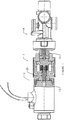
図1を参照すると、ブースターアクチュエータ10は、ソレノイド12又は他の電気的に作動する装置の本体に一端が螺着されており、同様に、危険状態の検出に応じてガスを所定領域に放出するようになったバルブ14に他端が連結されている。かくして、ブースター装置は、周囲環境を監視し、検出された状態に応じて電気信号を出力し、ソレノイド12を作動し、選択されたガス、例えば火災消火用のガスを放出する、比較的低エネルギの電気システムと関連して使用できる。図1に示すように、ソレノイド12は、ブースターアクチュエータ10の本体20に対して移動自在のプランジャー13を含む。アクチュエータ10は、この低エネルギ入力を受け取ってバルブ14の制御プランジャー15に高いエネルギを出力し、これによってバルブ14を作動し、圧縮ガスを環境に放出する。
Referring to FIG. 1, a
アクチュエータ10は、図2に示すように、力受け取り入力端22及び力送出出力端24を持つ本体20を含む。外スリーブ25は、従来のシール26と係合して本体の内部を密封するために設けられている。カムシャフト即ち力入力部材28は、ソレノイドのプランジャーの移動に応じ、本体に対し、図2に示す初期入力位置から作動出力位置まで移動できる。力出力部材30は、同様に、本体に対し、図2に示す初期出力位置から作動出力位置まで移動できる。4つのリンク32が力入力部材及び力出力部材の両方を中心として90°間隔で等間隔に間隔が隔てられている。これらのリンクの各々は、本体20に支持されたピン34を中心として枢動自在である。コイルばね46が力入力部材を初期入力位置に押圧し、ディスクばね48等の複数のディスクばねが出力部材30を作動出力位置に押圧する。
The
力入力部材28は、従来のO−リング50によって本体に関して密封されており、初期入力位置では、コイルばね46によって押圧され、本体の肩部52と係合する。入力部材28は、係合解除位置にあるときにリンク部材32の各々の上端を受け入れるための環状凹所54を含み、これによって、通常は各リンク部材の下端によって初期位置に保持された力出力部材30を解放できる。図2に示すように、各リンク32の上端に上ローラー56が設けられ、各リンクの下端に同様のローラー58が設けられている。アクチュエータが初期位置にあるとき、上ローラーの各々は、かくして、入力部材28の円筒形の外面64と係合しているのに対し、各下ローラー58は力出力部材30の環状凹所66内に少なくとも部分的に嵌まる。各ローラーは、リンクに固定された夫々のピン60でリンクに回転自在に取り付けられており、各リンク自体は、アクチュエータ本体20に支持されたピン34を中心として枢動自在である。かくして、入力部材28の位置により、四つのリンクの各々が図2に示す位置に保持される。これにより、力出力部材30がディスクばね48の作用で下方に移動しないようにする。
The
ストッププレート62には、力出力装置30のプランジャー68を受け入れる大きさの中央穴が設けられており、このストッププレートは本体にねじ70で相互連結されている。ストッププレートには、このストッププレートを所定位置にねじ込むのに適した工具を受け入れるため、従来のポート72が設けられており、ストッププレートは、その最終位置では、スナップリング74に載止する。O−リング76がストッププレート内の所定位置にバックアップリング及び保持リング78の組み合わせによって保持され、プランジャー68とストッププレート62との間を密封係合させる。
The stop plate 62 is provided with a central hole sized to receive the
本発明の特定的特徴は、コイルばね46の選択を変えることによって、入力部材28の移動に必要な力を容易に調節できるということである。コイルばねの大きさは、ブースターシステムに一般的に伝達される振動、揺さぶり、及び他の力に応じてアクチュエータが誤って作動されることがないように定められている。しかしながら、ばね46についてのコイルの数の選択及びコイルの材料の選択は、好ましくは複数のディスクばねである押圧部材48の選択とは別個に行われる。ディスクばねの数及びこれらのばねの互いに関する配向が、力出力部材を作動位置に移動する力及びストロークに影響する。これによって、プランジャーをストッププレートから延長し、例示の用途では、図1に示すバルブを作動する。この例示の実施例では、力出力部材が図2に示す初期位置から表面81がスナップリング74と係合する位置まで移動できるということは理解されるべきである。かくして、ローラー58の各々が移動して凹所66と係合した状態から外れたとき、力出力部材30を作動出力位置へ移動する。その結果、凹所から転がって出たローラー58の各々が力出力部材30の円筒形表面67と係合する。これと同時に、上ローラー56が力入力部材の円筒形表面64と係合した状態から転がって出て、これらのローラーを受け入れる大きさの環状凹所54内に少なくとも部分的に転がって入る。かくして、この作用によりリンク32を枢動させ、力出力部材を作動位置に解放する。
A particular feature of the present invention is that the force required to move the
図3は、適当なアクチュエータ本体20の構造、特にディスクばね48を受け入れるためのキャビティ80を詳細に示す。かくして、図2に示す最も上のディスクばねは、図3に示す表面82に当たる。図3及び図4もまた、周方向に間隔が隔てられた4対の案内プレート86及び88を示す。これによって、適当なリンク32を受け入れるためのスロット90をその間に形成する。図4は、更に、適当なリンクピン34を受け入れるための各案内プレート対の整合した通孔92を示す。本体20の下フランジ94は、本体20をソレノイドに容易に螺着するために従来の工具と係合する、六角形形体等の適当な外部形体を備えていてもよい。
FIG. 3 shows in detail the structure of a
本発明の一つの特徴は、本体20の内部及びかくして本体内の可動構成要素の各々が周囲環境からシールされているということである。この目的は、スリーブ25と本体との間を密封する従来のシール26によって、及び力入力部材及び力出力部材の夫々を密封するシール50及び76によって達成される。ねじの作用により、本体20とストッププレート62との間に十分な密封が形成されるが、所望であれば、ストッププレートと本体との間を密封するため、別のO−リングシールを設けてもよい。
One feature of the present invention is that the interior of the
好ましい実施例では、少なくとも三リンク部材が、力入力部材及び力出力部材を中心として周方向に配置されている。加わった力を入力部材及び出力部材を中心として等しく分配することによって120°間隔の三つのリンク部材が高い信頼性をもたらす。添付図面に示す好ましい実施例は90°間隔の四つのリンク部材を使用する。リンク部材の端部に設けられたローラー56及び58は、力出力部材30を初期出力位置に保持する図2に示す係合位置から、力出力部材を作動出力位置に解放する係合解除位置までリンク部材を移動するときの摩擦力を減少する。変形例では、ローラーをなくしてもよく、又は力入力部材及び力出力部材との摩擦を減少するための他の従来の部材と交換してもよい。
In a preferred embodiment, at least three link members are arranged circumferentially about the force input member and the force output member. Three link members spaced 120 ° provide high reliability by equally distributing the applied force about the input and output members. The preferred embodiment shown in the accompanying drawings uses four link members spaced 90 ° apart. The
コイルばね46は、力出力部材30と力入力部材28との間で作用する。このばねの力は、ブースター10の作動に必要な力を変化させるためにブースターアクチュエータの他の構成要素を変更することなく、容易に変化させることができる。同様に、ディスクばね48の大きさ、配向、及び数を変化させ、ストローク長及び/又は作動出力位置に移動したときにプランジャー68が出力する力に影響を及ぼすことができる。別の種類のばね又は他の押圧部材を使用してもよい。
The
本発明のブースターアクチュエータは、入力部材と出力部材とを機械的に離間する。コイルばね46は入力部材を初期位置に押圧するが、これにより、出力部材に加わる力はばね48の押圧力と比べて小さい。入力部材と出力部材との間を機械的に直接連結しないことにより、バルブに作用し、ブースターの作動中に力出力部材に戻される反作用力が力入力部材に、及び次いでソレノイドに伝達しないようにする。かくして、コイルばねは、出力部材に作用する反作用力を入力部材に加えられる力から分離し、ラッチソレノイド機構を使用してブースターをこれらの反作用力による損傷の恐れなしに作動できる。
The booster actuator of the present invention mechanically separates the input member and the output member. Although the
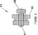
ブースターを作動した後、ブースターは、電子的装置を使用せずに、及び部品交換なしに容易にリセットできる。バルブ14をブースター本体から取り外し、図5に示すリセット装置94を本体に設けられたねじ70に連結できる。リセット外本体96をストッププレート62に当たるまでねじ込んだ後、ボルト98を外本体96に対して回転し、ピン97をストッププレート62に向かって突出させることができる。チップ97は、これによってプランジャー68の端部と強制的に係合され、これによって力出力部材30を図2に示す初期位置に押し戻す。力出力部材を初期位置に戻すことによって、コイルばねに作用する力を増大し、力入力部材を初期位置に戻す。
After activating the booster, the booster can be easily reset without using electronic devices and without changing parts. The valve 14 can be removed from the booster body and the
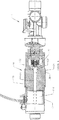
図6は、ソレノイド及びブースターアクチュエータの組み合わせを提供する本発明の別の実施例を示す。力入力部材128の右側までのブースター10の部分は上文中に説明した通りである。しかしながら、この実施例では、長さを延長した力入力部材128がソレノイドコイル114内に位置決めされるように、力入力部材を延長する。ソレノイドコイルは、磁気ラッチサブアッセンブリとも呼ばれ、電力を受け取って入力部材128を選択的に移動する。図示の長さを延長した力入力部材を使用でき、又はソレノイドプランジャーと力入力部材との間に二部品又は多部品の機械的相互連結部を形成できるということは当業者には理解されよう。かくして、コイル114を賦勢することにより、この場合に力入力部材128であるソレノイドプランジャーの移動を開始する。力入力部材128は、力入力部材の移動を制限するために表面132と係合するためのストップ130を含む。図6は、ソレノイド114を包囲するスリーブ134、スリーブ134をスリーブ25に連結する本体136を示す。
FIG. 6 illustrates another embodiment of the present invention that provides a combination solenoid and booster actuator. The portion of the
本発明の好ましい実施例を詳細に示したが、当業者は、ここに提案した実施例の変形及び変更を思いつくであろうということは明らかである。しかしながら、このような変形及び変更は、以下の特許請求の範囲に記載された本発明の精神及び範囲内にあるということは理解されよう。 Although preferred embodiments of the present invention have been shown in detail, it will be apparent to those skilled in the art that variations and modifications of the proposed embodiments may be envisaged. However, it will be understood that such variations and modifications are within the spirit and scope of the invention as set forth in the following claims.
10 ブースターアクチュエータ
12 ソレノイド
13 プランジャー
14 バルブ
15 制御プランジャー
20 本体
22 力受け取り入力端
24 力送出出力端
25 外スリーブ
26 シール
28 力入力部材
30 力出力部材
32 リンク
34 ピン
46 コイルばね
48 ディスクばね
50 O−リング
52 肩部
54 環状凹所
56 上ローラー
58 下ローラー
60 ピン
62 ストッププレート
64 外面
66 環状凹所
68 プランジャー
70 ねじ
72 ポート
74 スナップリング
76 O−リング
78 保持リング
DESCRIPTION OF
Claims (15)
力受け取り入力端及び力送出出力端を持つ本体と、
低エネルギ入力に応じて、初期入力位置から作動入力位置まで、前記本体の中で直線的に移動可能の力入力部材と、
前記力入力部材の移動に応じて初期出力位置から作動出力位置まで、前記本体の中で移動可能の力出力部材であって、前記高エネルギ出力は、前記低エネルギ入力に対して別個である、力出力部材と、
前記力入力部材を前記初期入力位置に押圧するための、前記本体の中にある入力押圧部材と、
前記力出力部材を押圧するための出力押圧部材と、
前記力入力部材と前記力出力部材との間に延びるリンク部材であって、当該リンク部材は、前記本体に対し、前記力出力部材を前記初期出力位置に保持するための係合位置から、前記力出力部材を前記作動出力位置に解放するための係合解除位置まで、移動可能であり、前記リンク部材は、前記力入力部材と係合する入力端及び前記力出力部材と係合する出力端を含み、前記リンク部材は、前記入力端と前記出力端との間の前記リンク部材の枢動位置で、前記本体に回転可能に連結される、リンク部材とを有する、ブースターアクチュエータ。In the booster actuator for outputting a high energy output receive low energy input,
A body having a force receiving input end and a force sending output end;
A force input member that is linearly movable within the body from an initial input position to an actuation input position in response to a low energy input;
A force output member movable within the body from an initial output position to an actuation output position in response to movement of the force input member, wherein the high energy output is separate from the low energy input; A force output member;
An input pressing member in the body for pressing the force input member to the initial input position;
An output pressing member for pressing the force output member;
A link member extending between the force input member and the force output member, the link member from the engagement position for holding the force output member at the initial output position relative to the main body; The link member is movable to an engagement disengagement position for releasing the force output member to the operation output position, and the link member has an input end engaged with the force input member and an output end engaged with the force output member. And the link member has a link member rotatably connected to the body at a pivot position of the link member between the input end and the output end.
前記力出力部材は、前記係合位置にある場合に、前記リンク部材の出力端を受け入れるための出力部材凹所を含む、ブースターアクチュエータ。The booster actuator according to claim 1,
The booster actuator, wherein the force output member includes an output member recess for receiving an output end of the link member when in the engaged position.
前記力入力部材は、前記係合解除位置にあるときに、前記リンク部材の入力端を受け入れるための入力部材凹所を含み、これによって前記リンク部材の前記出力端を前記出力部材凹所と係合した状態から外すことができる、ブースターアクチュエータ。The booster actuator according to claim 2,
The force input member includes an input member recess for receiving the input end of the link member when in the disengaged position, thereby engaging the output end of the link member with the output member recess. Booster actuator that can be removed from the combined state.
前記本体に対して各々が枢動可能の少なくとも三つのリンク部材が、前記力入力部材及び力出力部材を中心として周方向に配置されている、ブースターアクチュエータ。The booster actuator according to claim 1,
A booster actuator, wherein at least three link members each pivotable with respect to the main body are arranged in a circumferential direction around the force input member and the force output member.
四つのリンク部材が、前記力入力部材及び力出力部材を中心として周方向に約90°間隔で間隔が隔てられている、ブースターアクチュエータ。The booster actuator according to claim 4,
A booster actuator in which four link members are spaced apart at an interval of about 90 ° in the circumferential direction around the force input member and the force output member.
複数のディスクばねを含む前記出力押圧部材を更に含む、ブースターアクチュエータ。The booster actuator according to claim 1,
The booster actuator further comprising the output pressing member including a plurality of disk springs.
加えられた電気エネルギの変化により前記力入力部材を前記作動入力位置に移動するように、前記力入力部材を取り囲む電気コイルを更に含む、ブースターアクチュエータ。The booster actuator according to claim 1,
A booster actuator further comprising an electrical coil surrounding the force input member to move the force input member to the actuated input position by a change in applied electrical energy.
前記力入力部材及び前記力出力部材の夫々と係合するためのローラーが、前記リンク部材の前記入力端及び前記出力端の各々に設けられている、ブースターアクチュエータ。The booster actuator according to claim 1,
A booster actuator, wherein a roller for engaging with each of the force input member and the force output member is provided at each of the input end and the output end of the link member.
前記本体の前記力送出出力端にはねじ山が設けられており、前記送出出力端にねじ込んだリセット部材を、前記本体に対して回転させて前記力出力部材と強制的に係合させて、前記力出力部材を前記作動位置から前記初期位置まで移動する、ブースターアクチュエータ。The booster actuator according to claim 1,
The force delivery output end of the main body is provided with a thread, and a reset member screwed into the delivery output end is rotated with respect to the main body to forcibly engage with the force output member, A booster actuator that moves the force output member from the operating position to the initial position.
前記リンク部材は、前記力出力部材を前記初期出力位置に保持するための係合位置から、前記力出力部材を前記作動出力位置に解放するための係合解除位置まで移動可能である、ブースターアクチュエータ。The booster actuator according to claim 2,
The link member is movable from an engagement position for holding the force output member at the initial output position to an engagement release position for releasing the force output member to the operation output position. .
前記本体と前記力入力部材との間のシールを更に含む、ブースターアクチュエータ。The booster actuator according to claim 1,
A booster actuator further comprising a seal between the body and the force input member.
前記入力押圧部材はコイルばねであり、前記出力押圧部材は複数のディスクばねを含む、ブースターアクチュエータ。The booster actuator according to claim 1,
The booster actuator, wherein the input pressing member is a coil spring, and the output pressing member includes a plurality of disc springs.
前記低エネルギ入力を電気作動装置から受け取り、前記高エネルギ出力は、危険な領域への加圧ガスの放出を賦勢する、ブースターアクチュエータ。The booster actuator according to claim 1,
A booster actuator that receives the low energy input from an electrical actuator and the high energy output energizes the release of pressurized gas into a hazardous area.
Applications Claiming Priority (2)
| Application Number | Priority Date | Filing Date | Title |
|---|---|---|---|
| US09/907,195 US6722216B2 (en) | 2001-07-17 | 2001-07-17 | Booster actuator |
| PCT/US2002/015904 WO2003008810A1 (en) | 2001-07-17 | 2002-05-20 | Booster actuator |
Publications (3)
| Publication Number | Publication Date |
|---|---|
| JP2004537686A JP2004537686A (en) | 2004-12-16 |
| JP2004537686A5 JP2004537686A5 (en) | 2005-12-22 |
| JP4195376B2 true JP4195376B2 (en) | 2008-12-10 |
Family
ID=25423673
Family Applications (1)
| Application Number | Title | Priority Date | Filing Date |
|---|---|---|---|
| JP2003514123A Expired - Fee Related JP4195376B2 (en) | 2001-07-17 | 2002-05-20 | Booster actuator |
Country Status (18)
| Country | Link |
|---|---|
| US (3) | US6722216B2 (en) |
| EP (1) | EP1407149B1 (en) |
| JP (1) | JP4195376B2 (en) |
| KR (1) | KR100908509B1 (en) |
| CN (1) | CN100374739C (en) |
| AT (1) | ATE435979T1 (en) |
| AU (1) | AU2002320034B2 (en) |
| BR (1) | BR0211153B1 (en) |
| CA (1) | CA2453576C (en) |
| DE (1) | DE60232881D1 (en) |
| DK (1) | DK1407149T3 (en) |
| ES (1) | ES2328798T3 (en) |
| HK (1) | HK1068388A1 (en) |
| MX (1) | MXPA04000383A (en) |
| NO (1) | NO329075B1 (en) |
| RU (1) | RU2285820C2 (en) |
| WO (1) | WO2003008810A1 (en) |
| ZA (1) | ZA200400291B (en) |
Families Citing this family (7)
| Publication number | Priority date | Publication date | Assignee | Title |
|---|---|---|---|---|
| US6722216B2 (en) * | 2001-07-17 | 2004-04-20 | Ansul Incorporated | Booster actuator |
| US7380755B2 (en) * | 2005-05-26 | 2008-06-03 | Goodrich Corporation | Frangible pneumatic latch |
| RU2459977C1 (en) * | 2010-12-08 | 2012-08-27 | Георгий Владимирович Варламов | Spring drive |
| US8640783B2 (en) | 2011-06-14 | 2014-02-04 | Tlx Technologies, Llc | Solenoid interlock for booster actuator |
| CN102829232B (en) * | 2011-06-14 | 2016-02-24 | Tlx技术有限公司 | For the solenoid interlock of booster actuator |
| US9038742B2 (en) * | 2011-08-02 | 2015-05-26 | Kidde Technologies, Inc. | Suppressant actuator |
| US8757191B2 (en) * | 2011-12-08 | 2014-06-24 | Kiddie Technologies, Inc. | High rate discharge (HRD) valve opening mechanism for a fire and explosion protection |
Family Cites Families (20)
| Publication number | Priority date | Publication date | Assignee | Title |
|---|---|---|---|---|
| US3610050A (en) * | 1970-01-19 | 1971-10-05 | Ibm | Mechanical interlock mechanism for a carriage assembly |
| US3638501A (en) * | 1970-04-27 | 1972-02-01 | Gen Motors Corp | Sensor |
| DE2741166C2 (en) * | 1977-09-13 | 1985-11-07 | A. Ott Gmbh, 8960 Kempten | Device for actuating a clamping head |
| CH622837A5 (en) * | 1977-12-06 | 1981-04-30 | Saurer Ag Adolph | |
| US4309022A (en) * | 1980-04-14 | 1982-01-05 | Consolidated Controls Corporation | Poppet valve actuator apparatus |
| JPH0248841Y2 (en) * | 1983-10-14 | 1990-12-21 | ||
| US4549719A (en) * | 1984-02-02 | 1985-10-29 | Baumann Hans D | Mechanical amplifying means for valves and other devices |
| FR2575524B1 (en) * | 1985-01-03 | 1987-01-30 | Commissariat Energie Atomique | OPERATING DEVICE FOR USE IN A HIGH PRESSURE FLUID |
| FR2612570A1 (en) * | 1987-03-17 | 1988-09-23 | Alsthom | MECHANICAL ENERGY STORAGE DEVICE HAVING NULL ACCELERATION STRENGTH |
| US4881745A (en) * | 1988-04-25 | 1989-11-21 | Peters Roger D | Mechanical plate clamp |
| US5119841A (en) * | 1991-02-26 | 1992-06-09 | Mcgill James C | Safety shut off apparatus |
| US5141405A (en) * | 1991-11-20 | 1992-08-25 | Francart Jr Armand | Leak proof, preloaded, high-biasing force float-operated over-center valve actuating mechanism |
| US5445501A (en) * | 1993-03-17 | 1995-08-29 | Tlv Co., Ltd. | Snap action float valve assembly for liquid feeding device |
| DE4431624C1 (en) * | 1994-09-05 | 1996-01-04 | Immanuel Jeschke | Gas inlet into building |
| JP3616855B2 (en) * | 1995-03-13 | 2005-02-02 | 株式会社フジキン | Controller |
| US5771742A (en) * | 1995-09-11 | 1998-06-30 | Tini Alloy Company | Release device for retaining pin |
| TW379155B (en) * | 1997-10-31 | 2000-01-11 | Kosmek Kk | Transmission apparatus |
| JP3954704B2 (en) * | 1997-10-31 | 2007-08-08 | 株式会社コスメック | Clamping device |
| DE19808301A1 (en) * | 1998-02-27 | 1998-09-10 | Ulrich Dr Stahl | Force increaser for cylinder |
| US6722216B2 (en) * | 2001-07-17 | 2004-04-20 | Ansul Incorporated | Booster actuator |
-
2001
- 2001-07-17 US US09/907,195 patent/US6722216B2/en not_active Expired - Lifetime
-
2002
- 2002-05-20 CA CA 2453576 patent/CA2453576C/en not_active Expired - Fee Related
- 2002-05-20 CN CNB028144031A patent/CN100374739C/en not_active Expired - Lifetime
- 2002-05-20 ES ES02749532T patent/ES2328798T3/en not_active Expired - Lifetime
- 2002-05-20 EP EP20020749532 patent/EP1407149B1/en not_active Expired - Lifetime
- 2002-05-20 KR KR1020047000720A patent/KR100908509B1/en active IP Right Grant
- 2002-05-20 DK DK02749532T patent/DK1407149T3/en active
- 2002-05-20 JP JP2003514123A patent/JP4195376B2/en not_active Expired - Fee Related
- 2002-05-20 AT AT02749532T patent/ATE435979T1/en not_active IP Right Cessation
- 2002-05-20 RU RU2004104947A patent/RU2285820C2/en active
- 2002-05-20 MX MXPA04000383A patent/MXPA04000383A/en active IP Right Grant
- 2002-05-20 AU AU2002320034A patent/AU2002320034B2/en not_active Expired
- 2002-05-20 DE DE60232881T patent/DE60232881D1/en not_active Expired - Lifetime
- 2002-05-20 BR BRPI0211153-5A patent/BR0211153B1/en not_active IP Right Cessation
- 2002-05-20 WO PCT/US2002/015904 patent/WO2003008810A1/en active IP Right Grant
-
2004
- 2004-01-14 ZA ZA200400291A patent/ZA200400291B/en unknown
- 2004-01-16 NO NO20040190A patent/NO329075B1/en not_active IP Right Cessation
- 2004-03-15 US US10/800,520 patent/US7021166B2/en not_active Expired - Lifetime
- 2004-10-29 US US10/977,981 patent/US7444893B2/en not_active Expired - Lifetime
-
2005
- 2005-01-13 HK HK05100321A patent/HK1068388A1/en not_active IP Right Cessation
Also Published As
| Publication number | Publication date |
|---|---|
| CA2453576C (en) | 2011-01-11 |
| US20040173768A1 (en) | 2004-09-09 |
| RU2285820C2 (en) | 2006-10-20 |
| CN100374739C (en) | 2008-03-12 |
| US20070163369A9 (en) | 2007-07-19 |
| US6722216B2 (en) | 2004-04-20 |
| ATE435979T1 (en) | 2009-07-15 |
| KR100908509B1 (en) | 2009-07-20 |
| ES2328798T3 (en) | 2009-11-18 |
| BR0211153B1 (en) | 2011-02-22 |
| NO20040190L (en) | 2004-03-11 |
| RU2004104947A (en) | 2005-05-20 |
| US7444893B2 (en) | 2008-11-04 |
| MXPA04000383A (en) | 2004-07-23 |
| DK1407149T3 (en) | 2009-10-05 |
| ZA200400291B (en) | 2004-10-19 |
| US20050199081A1 (en) | 2005-09-15 |
| HK1068388A1 (en) | 2005-04-29 |
| AU2002320034B2 (en) | 2007-07-26 |
| CN1533481A (en) | 2004-09-29 |
| DE60232881D1 (en) | 2009-08-20 |
| EP1407149B1 (en) | 2009-07-08 |
| KR20040017311A (en) | 2004-02-26 |
| WO2003008810A1 (en) | 2003-01-30 |
| EP1407149A1 (en) | 2004-04-14 |
| NO329075B1 (en) | 2010-08-16 |
| BR0211153A (en) | 2005-05-10 |
| JP2004537686A (en) | 2004-12-16 |
| US7021166B2 (en) | 2006-04-04 |
| US20030015049A1 (en) | 2003-01-23 |
| CA2453576A1 (en) | 2003-01-30 |
Similar Documents
| Publication | Publication Date | Title |
|---|---|---|
| JP4195376B2 (en) | Booster actuator | |
| US8640783B2 (en) | Solenoid interlock for booster actuator | |
| KR101354780B1 (en) | Suppressant actuator | |
| WO1996023979A1 (en) | Brake system for linearly movable bodies | |
| AU2002320034A1 (en) | Booster actuator | |
| JP2002154024A (en) | Clamping device | |
| CN102829232A (en) | Solenoid interlock for booster actuator | |
| KR100834197B1 (en) | Pin puller device | |
| JP2001299951A (en) | Opening device for differential pressure type gas cylinder valve | |
| SG187371A1 (en) | Suppressant actuator | |
| US11854753B2 (en) | Safety switch actuation device | |
| JPS5912909B2 (en) | Valve operating mechanism | |
| JP2006118599A (en) | Axial one-way clutch | |
| JP2006125498A (en) | Axial one-way clutch |
Legal Events
| Date | Code | Title | Description |
|---|---|---|---|
| A521 | Request for written amendment filed |
Free format text: JAPANESE INTERMEDIATE CODE: A523 Effective date: 20050218 |
|
| A621 | Written request for application examination |
Free format text: JAPANESE INTERMEDIATE CODE: A621 Effective date: 20050218 |
|
| A977 | Report on retrieval |
Free format text: JAPANESE INTERMEDIATE CODE: A971007 Effective date: 20070131 |
|
| A131 | Notification of reasons for refusal |
Free format text: JAPANESE INTERMEDIATE CODE: A131 Effective date: 20070206 |
|
| A601 | Written request for extension of time |
Free format text: JAPANESE INTERMEDIATE CODE: A601 Effective date: 20070207 |
|
| A602 | Written permission of extension of time |
Free format text: JAPANESE INTERMEDIATE CODE: A602 Effective date: 20070215 |
|
| A521 | Request for written amendment filed |
Free format text: JAPANESE INTERMEDIATE CODE: A523 Effective date: 20070801 |
|
| A131 | Notification of reasons for refusal |
Free format text: JAPANESE INTERMEDIATE CODE: A131 Effective date: 20080401 |
|
| A601 | Written request for extension of time |
Free format text: JAPANESE INTERMEDIATE CODE: A601 Effective date: 20080630 |
|
| A602 | Written permission of extension of time |
Free format text: JAPANESE INTERMEDIATE CODE: A602 Effective date: 20080707 |
|
| A601 | Written request for extension of time |
Free format text: JAPANESE INTERMEDIATE CODE: A601 Effective date: 20080731 |
|
| A602 | Written permission of extension of time |
Free format text: JAPANESE INTERMEDIATE CODE: A602 Effective date: 20080807 |
|
| A521 | Request for written amendment filed |
Free format text: JAPANESE INTERMEDIATE CODE: A523 Effective date: 20080811 |
|
| A521 | Request for written amendment filed |
Free format text: JAPANESE INTERMEDIATE CODE: A523 Effective date: 20080812 |
|
| TRDD | Decision of grant or rejection written | ||
| A01 | Written decision to grant a patent or to grant a registration (utility model) |
Free format text: JAPANESE INTERMEDIATE CODE: A01 Effective date: 20080909 |
|
| A01 | Written decision to grant a patent or to grant a registration (utility model) |
Free format text: JAPANESE INTERMEDIATE CODE: A01 |
|
| A61 | First payment of annual fees (during grant procedure) |
Free format text: JAPANESE INTERMEDIATE CODE: A61 Effective date: 20080925 |
|
| R150 | Certificate of patent or registration of utility model |
Ref document number: 4195376 Country of ref document: JP Free format text: JAPANESE INTERMEDIATE CODE: R150 Free format text: JAPANESE INTERMEDIATE CODE: R150 |
|
| FPAY | Renewal fee payment (event date is renewal date of database) |
Free format text: PAYMENT UNTIL: 20111003 Year of fee payment: 3 |
|
| FPAY | Renewal fee payment (event date is renewal date of database) |
Free format text: PAYMENT UNTIL: 20111003 Year of fee payment: 3 |
|
| S111 | Request for change of ownership or part of ownership |
Free format text: JAPANESE INTERMEDIATE CODE: R313111 |
|
| FPAY | Renewal fee payment (event date is renewal date of database) |
Free format text: PAYMENT UNTIL: 20111003 Year of fee payment: 3 |
|
| R360 | Written notification for declining of transfer of rights |
Free format text: JAPANESE INTERMEDIATE CODE: R360 |
|
| FPAY | Renewal fee payment (event date is renewal date of database) |
Free format text: PAYMENT UNTIL: 20111003 Year of fee payment: 3 |
|
| R360 | Written notification for declining of transfer of rights |
Free format text: JAPANESE INTERMEDIATE CODE: R360 |
|
| R371 | Transfer withdrawn |
Free format text: JAPANESE INTERMEDIATE CODE: R371 |
|
| S111 | Request for change of ownership or part of ownership |
Free format text: JAPANESE INTERMEDIATE CODE: R313111 |
|
| FPAY | Renewal fee payment (event date is renewal date of database) |
Free format text: PAYMENT UNTIL: 20111003 Year of fee payment: 3 |
|
| R350 | Written notification of registration of transfer |
Free format text: JAPANESE INTERMEDIATE CODE: R350 |
|
| FPAY | Renewal fee payment (event date is renewal date of database) |
Free format text: PAYMENT UNTIL: 20121003 Year of fee payment: 4 |
|
| R250 | Receipt of annual fees |
Free format text: JAPANESE INTERMEDIATE CODE: R250 |
|
| FPAY | Renewal fee payment (event date is renewal date of database) |
Free format text: PAYMENT UNTIL: 20131003 Year of fee payment: 5 |
|
| R250 | Receipt of annual fees |
Free format text: JAPANESE INTERMEDIATE CODE: R250 |
|
| R250 | Receipt of annual fees |
Free format text: JAPANESE INTERMEDIATE CODE: R250 |
|
| R250 | Receipt of annual fees |
Free format text: JAPANESE INTERMEDIATE CODE: R250 |
|
| R250 | Receipt of annual fees |
Free format text: JAPANESE INTERMEDIATE CODE: R250 |
|
| R250 | Receipt of annual fees |
Free format text: JAPANESE INTERMEDIATE CODE: R250 |
|
| R250 | Receipt of annual fees |
Free format text: JAPANESE INTERMEDIATE CODE: R250 |
|
| R250 | Receipt of annual fees |
Free format text: JAPANESE INTERMEDIATE CODE: R250 |
|
| R250 | Receipt of annual fees |
Free format text: JAPANESE INTERMEDIATE CODE: R250 |
|
| R250 | Receipt of annual fees |
Free format text: JAPANESE INTERMEDIATE CODE: R250 |
|
| LAPS | Cancellation because of no payment of annual fees |