JP4189552B2 - Structure of the inner collar and the collar cover - Google Patents
Structure of the inner collar and the collar cover Download PDFInfo
- Publication number
- JP4189552B2 JP4189552B2 JP2000258236A JP2000258236A JP4189552B2 JP 4189552 B2 JP4189552 B2 JP 4189552B2 JP 2000258236 A JP2000258236 A JP 2000258236A JP 2000258236 A JP2000258236 A JP 2000258236A JP 4189552 B2 JP4189552 B2 JP 4189552B2
- Authority
- JP
- Japan
- Prior art keywords
- piece
- cover
- roof
- pressing member
- pressing
- Prior art date
- Legal status (The legal status is an assumption and is not a legal conclusion. Google has not performed a legal analysis and makes no representation as to the accuracy of the status listed.)
- Expired - Fee Related
Links
Images


Landscapes
- Roof Covering Using Slabs Or Stiff Sheets (AREA)
Description
【0001】
【発明の属する技術分野】
本願は、第1〜第3の発明及びこれらの組み合わせの発明から成り、第1の発明は、一般住宅、学校、集会所、病院等の大型屋根の内樋の構造に関し、更に詳細には、寒暖の差による屋根材の伸縮亀裂を防止し、更に、降雪に対して滑り落ち防止効果を備えた内樋の構造に関し、次いで、第2の発明は、上記内樋の開放上面を覆って、上記内樋の施工後でも取り付けが容易なカバーの構造に関し、更に、第3の発明は、該カバーが構造が簡潔で且つ雪止め効果を有するカバーの構造に関する。更に、これら第1〜第3の発明を組み合わせた発明に関する。
【0002】
【従来の技術】
内樋とは、軒先の設けられる一般の雨樋に対し、軒先から若干屋根の上部(内側)に配される樋をいう。
該内樋は、一般に、上側を開放した断面コの字型で横方向に延長させてトタン材を屈曲させて成形し、これを接合部で重ね合わせ、その接合部を釘打ち等して結合させている。
そして、その成形は多く、現場施工であり、屋根の内樋を設けるべき位置に溝を形成し、そこに防水シートを覆う方法に頼っている。
又、上記内樋には落ち葉等が侵入して詰まりの原因となるので網のキャップを施すのが望ましいが、上記内樋を形成した後に現場で網体を成形してキャップに加工しなければならず、極めて面倒な作業とならざるを得ない。
【0003】
しかし、上記構造及び手法によれば、(a)春夏及び昼夜の寒暖の差によって、トタン材等の金属製素材の屋根部材には熱膨張及び収縮が生じ、結合部に亀裂が起こり易く、漏水を惹起する大きな原因となる。(b)比較的複雑な形状の内樋の溝に合わせて現場でトタン等を加工することは、熟練した職人の技を必要とすると共に、作業効率が悪く、施工費が高価なものとなる等の欠点があった。
【0004】
又、第二の問題は、上記内樋は、上側が開放されているので、そこから落ち葉等が侵入して、詰まりを起こす原因となるので、上面を覆うカバーを付設させる必要が生じるが、該カバーは上記内樋を取り付けた後で取り付けねばならず、作業が極めて困難であった。
【0005】
更に、第三には屋根に降雪があった場合に、その落下を防止する為に屋根に雪止めが必要であり、従来、この雪止めは屋根材の一部に突起を出して滑動を防ぐのが一般的であるが、構造的に複雑であり、工事費用が高いものとなっていた。
【0006】
【発明が解決しようとする課題】
これら欠点を解消すべく本発明はなされたもので、(a)寒暖差による熱収縮があっても雨漏れを起こさず、且つ、工場生産したものを現場で組み立て可能な内樋の構造を開発し、(b)該内樋の施工後にあっても、取り付けが容易な樋カバーの構造を開発し、(c)更に、該樋カバーがそれ自身で雪止め効果を備える樋カバーを開発し、更にこれらを組み合わせによる相乗的効果を導き出そうとするものである。
【0007】
【課題を解決するための手段】
本願第1の内樋の発明は、軒先より内側に形成される屋根の内樋において、上面開放の箱形で独立して雨水を貯留可能な受樋本体を内樋用凹部に沿って連設し、隣接する該受樋本の間に寒暖差による受樋本体の熱伸縮を吸収し得る幅寸法を有する断面コの字状のジョイント部を上側から跨設し、該受樋本体の一部に貯留した雨水を地下部へと導くドレンを付設したことを特徴として構成される。
【0008】
又、第2の樋カバーの構造の発明は、(a)開放された受樋本体の上部を覆う有孔樋カバーと、(b)突出部の上側に載って屋根材を上から押さえる屋根押止片と、内樋側に入って樋カバーを上側から挟み込むカバー挟片とから成る押さえ部材上片と、該突出部の上側に載った屋根押止片と、内樋側に載って樋カバーを下側から挟み込むカバー挟片と、その中間で上記押さえ部材上片より樋カバーの厚みに対応させて長い段部を設けた押さえ部材下片とから成る上側押さえ部材と、(c)屋根材の突出部の下側に沿って、これを下側から押さえる屋根押さえ片と、上記屋根押さえ片の下側に沿ってこれを支える押片と、ナットの回転を抑止するナット抑え片と、中間段部とから成る下側押さえ部材と、(d)上記上側押さえ部材及び下側押さえ部材の内樋側には、ボルト用通孔及び位置調整の為の長孔を穿設すると共に締結用のボルト・ナットを配して成る。
【0009】
上記第1と第2の発明を組み合わせて、(イ)軒先より内側に形成される屋根の内樋において、上面開放の箱形で独立して雨水を貯留可能な受樋本体を内樋用凹部に沿って連設し、隣接する該受樋本の間に寒暖差による受樋本体の熱伸縮を吸収し得る幅寸法を有する断面コの字状のジョイント部を上側から跨設し、該受樋本体の一部に貯留した雨水を地下部へと導くドレンを付設し、(ロ)(a)開放された受樋本体の上部を覆う有孔樋カバーと、(b)突出部の上側に載って屋根材を上から押さえる屋根押止片と、内樋側に入って樋カバーを上側から挟み込むカバー挟片とから成る押さえ部材上片と、該突出部の上側に載った屋根押止片と、内樋側に載って樋カバーを下側から挟み込むカバー挟片と、その中間で上記押さえ部材上片より樋カバーの厚みに対応させて長い段部を設けた押さえ部材下片とから成る上側押さえ部材と、(c)屋根材の突出部の下側に沿って、これを下側から押さえる屋根押さえ片と、上記屋根押さえ片の下側に沿ってこれを支える押片と、ナットの回転を抑止するナット抑え片と、中間段部とから成る下側押さえ部材と、(d)上記上側押さえ部材及び下側押さえ部材の内樋側には、ボルト用通孔及び位置調整の為の長孔を穿設すると共に締結用のボルト・ナットを配して成る内樋の発明を構成する。
【0010】
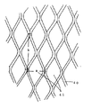
更に、第3の樋カバー発明は、菱形に形成したエキスパンドメタルから成り、その菱形が12×30.5〜34×76.2mmの範囲で、且つ、菱形の長手方向が上下縦方向となるよう配設して雪止め効果を有することを特徴として構成される。
【0011】
更に、上記第1の発明と第2の発明と第3の発明を組み合わせて、(イ)軒先より内側に形成される屋根の内樋において、上面開放の箱形で独立して雨水を貯留可能な受樋本体を内樋用凹部に沿って連設し、隣接する該受樋本の間に寒暖差による受樋本体の熱伸縮を吸収し得る幅寸法を有する断面コの字状のジョイント部を上側から跨設し、該受樋本体の一部に貯留した雨水を地下部へと導くドレンを付設し、(ロ)(a)開放された受樋本体の上部を覆う有孔樋カバーと、(b)突出部の上側に載って屋根材を上から押さえる屋根押止片と、内樋側に入って樋カバーを上側から挟み込むカバー挟片とから成る押さえ部材上片と、該突出部の上側に載った屋根押止片と、内樋側に載って樋カバーを下側から挟み込むカバー挟片と、その中間で上記押さえ部材上片より樋カバーの厚みに対応させて長い段部を設けた押さえ部材下片とから成る上側押さえ部材と、(c)屋根材の突出部の下側に沿って、これを下側から押さえる屋根押さえ片と、上記屋根押さえ片の下側に沿ってこれを支える押片と、ナットの回転を抑止するナット抑え片と、中間段部とから成る下側押さえ部材と、(d)上記上側押さえ部材及び下側押さえ部材の内樋側には、ボルト用通孔及び位置調整の為の長孔を穿設すると共に締結用のボルト・ナットを配して成り、(c)該樋カバーが菱形に形成したエキスパンドメタルから成り、その菱形が12×30.5〜34×76.2mmの範囲で、且つ、菱形の長手方向が上下縦方向となるよう配設して雪止め効果を有することを特徴とする内樋の構造の発明を構成する。
【0012】
【発明の実施の形態】
本願第1の発明の実施の形態を説明すると、前後左右に壁面を形成し、それ単独で雨水を貯留可能な箱形を形成する受樋本体10と、それを左右に連続させるべく結合させるジョイント部20と、貯留した雨水を地下へと導くドレン部30とから成る。
【0013】
先ず、受樋本体10は、底面11の前後に前壁12、後壁13を配し、左右に側壁14,15を配設して、上面開放の、それ単独で雨水を貯留可能な箱形に形成する。
即ち、横方向に連続させて雨水を流下させるべき従来の樋の構造を廃し、受樋本体を幾つかの独立した箱体に区分させるべき構造とし、そこに雨水を貯留させて、処理する構造とする。
該前壁12と後壁13とは、屋根の勾配に合わせて高さに差異を設け、側壁14,15にも勾配を付す。
又、該前壁12,後壁13には、内側又は外側に折り曲げて、屋根材との結合を図る突出部16,突出部17を形成するのが望ましい。図1、図2には、折曲片を内側に屈曲させた場合を示したが、図4、図8〜図10には、外側に屈曲させた場合を例示した。
【0014】
該受樋10,10の左右に連続する隣接部には、寒暖の差による受樋の伸縮を調整しつつ両者の隙間埋めて漏水を防止するジョイント部20を形成する。
該ジョイント部20は、先ず、左右の受樋の側壁14,14の上側を跨ぐべく下向きコの字状の胴体21を形成し、該胴体21のコの字の幅は、受樋本体10,10の寒暖の差による熱伸縮を充分に吸収し得る幅寸法とする。
そして、該胴体21の前に前壁12と当接する当接片22と、突出部17と接するジョイント折曲片23とを形成する。
【0015】
該ジョイント部20は、上記形態のものを一つでも良いが、望ましくは図1に示す如く、上下二つに分割し、コの字型胴体21に若干の太細の違い設けて、胴体同士が摺動してスライド自在とし、そのスライドによって上下方向に長さ調整が可能な態様とするのが望ましい。
【0016】
上記受樋本体10は、左右いずれか一方に若干の高低差を付し、その下流の溜まり部に、箱形の受樋本体10に貯留した雨水を地下部に流下させるドレン30を連結させる。
【0017】
次に、上記内樋に関する第1の発明に対して、落ち葉等の侵入を防止する為の孔空き樋カバーの構造に関する第2の発明の実施の形態を説明する。
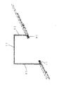
内樋とは、図3に示す如くで、軒先から若干屋根側に入った位置に雨等を収集して排出するトタン等で形成する受樋本体10を配設する。
そのとき、樋の下端側には樋内側に向けて突き出る突出部16を形成し、例えば図1,図2の如く折曲片でも良いが、図4に示す如く葺き板16aに唐草と呼ばれる役物16bをつかみ込んで形成して置くのが望ましい。
又、樋の内側上端部にも、突出部17を形成するが、例えば図1,2の如く折曲片に形成しても良いが、図4に示す如く屋根片から延設された上掛止片17aと、同様に屋根片から一定間隔を保って下側に並設させる下掛止片17bとから成る突出部17を形成して置くのが望ましい。
上記内樋は、上側が開放されているので、そこから落ち葉等が侵入し、詰まりを起こす原因となるので、雨水を通しつつこれらを防止する有孔の樋カバー40を配設する。
【0018】
更に、該樋カバー40には、該樋カバーを屋根部材に固定させる上側押さえ部材50と下側押さえ部材60を配設する。
即ち、上側押さえ部材50は、図5に示す如く、突出部の上側に載って屋根部材を上から押さえる屋根押止片51aと、内樋側に入って樋カバーを上側から挟み込む上カバー挟片51bと、その中間の段部51cとから成る押さえ部材上片51と、同様に突出部の上側に載った屋根押止片52aと、内樋側に載って樋カバーを下側から挟み込む下カバー挟片52bと、その中間で上記押さえ部材上片より長い段部52cを形成した押さえ部材下片52とから成る。
このとき、該押さえ部材上片51の段部51cは必要に応じて設けるものであるが、押さえ部材下片52の段部52cは樋カバーを挟む為に不可欠なものである。
【0019】
下側押さえ部材60は、屋根部材の突出部20の下側に沿って、これを下側から押さえる屋根押止片60aと、上記屋根押止片60aの下側に沿ってこれを支える押片60bと、ナットの回転を抑止するナット抑え片60dと、中間段部60eとから成る。
この上部押さえ部材50及び下側押さえ部材60の内樋側には、ボルト用通孔を穿設し、該下側押さえ部材60の通孔60dは位置調整の為の長孔とする。
【0020】
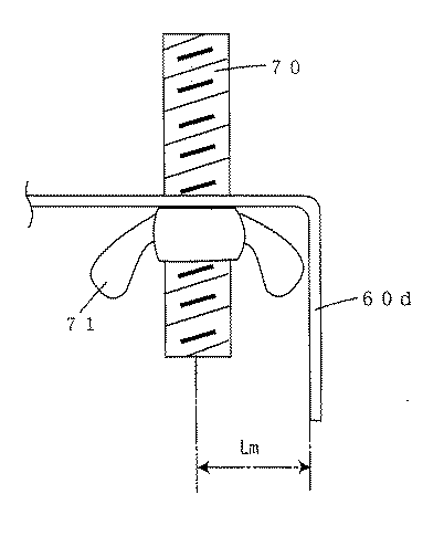
そして、上述の如く、上側押さえ部材50及び下側押さえ部材60の通孔には、ボルト70を挿通させてナット71の締付けによって両者の結合を図るが、このとき重要なのは、下側押さえ部材60とナット71との関係である。
先ず、図6及び図7に示す如く、ナット71には、その長径(RA)と短径(RB)とが異なる形状の異径ナットを用い、少なくとも円形ナットの使用は排する。
そして、そのナット71の中心位置からナット抑え片60d迄の距離をLmとしたとき、
RB<Lm<RA
の条件を満たすナット抑え片を形成しなければならない。
【0021】
尚、受樋本体10の上側には、当該樋カバー40を受ける為の支持片80を配設し、一方が屋根材と結合し、他方が樋カバー40を嵌入させる形態とする。
又、折曲片を外側に屈曲させた場合には、前壁12に添わせて鈎型の掛止片12aを配設し、屋根部材を屈曲させて雨仕舞いさせるのが望ましい。
【0022】
更に、第3の樋カバー発明は、菱形に形成したエキスパンドメタルから成り、その菱形が、図11に示すごとく、12×30.5〜34×76.2mm(横幅×縦幅)の範囲とし、菱形の長手方向が上下縦方向となるよう配設する。
【0023】
本発明内樋は、受樋本体及びジョイント部を、工場で一定規格の基に量産が可能であり、予め工場生産によって生産した受樋本体等を建築現場に搬送する。そして、それを屋根部材の受樋本体10の内樋用凹部に形成された屋根の所定位置に据え置く。このとき、受樋本体10の突出部16及び突出部17と屋根葺きトタンとを互いに屈曲嵌合させて結合させる。受樋本体10が比較的小さい場合には、図6の如く、野地板に釘打ち等で支えるべく突出部16及び突出部17を外側に屈曲させ、受樋本体10が大型で重い場合には、図3の如く、周辺を柱材で支持しつつ突出部16及び突出部17を内側に屈曲させる。
【0024】
斯くして受樋本体を並列に配設した後、その並設させた受樋の隣り同士にジョイント部20を介設させる。
該ジョイント部20の取り付けは、断面コの字状の胴体21を隣接する受樋本体10の側壁14,14に跨らせて嵌入し、両者間の隙間を上側から傘のように覆う形態とし、上下に分割させた場合には、二つの胴体21,21を摺動させつつ、前方の当接片22を受樋本体10の前壁12に当て、後方の当接片23を受樋本体10の後壁13に当接させる。
最後に、受樋本体10のドレン40を所定の地下部へと導いて、本発明内樋の取り付けは完了する。
【0025】
そして、樋として作用させるに、降雨があった場合、傾斜した屋根から雨水が流下して受樋本体10へと流れ込み、これが一旦、箱型で互いに独立した受樋本体10に貯留される。このとき、受樋本体10の隙間に流下した雨水は、隣接する受樋本体10の隙間をジョイント部20が塞いで、左右いずれかの受樋本体10に導かれる。そして、該受樋本体10に貯留された雨水は、各受樋本体10に個別に配設されたドレン40によって地下部へと浸透する。
【0026】
ところで、該受樋本体10は、夏冬の季節の違い、又、昼夜の寒暖の差によって、長手方向に熱膨張及び収縮を数mm〜数cmの単位で繰り返す。すると、従来の内樋では、その動きによって結合部に亀裂等が生じてしまい、雨漏れの原因となっていた。
しかし、本発明内樋では、受樋が長手方向に伸びると、受樋本体10は互いに独立して形成され、両者間に隙間が介在するので、該隙間によって収縮分が吸収され、結合部での亀裂等を起こさない。且つ、その隙間は断面下向きコの字状のジョイント胴体21が両者間に跨って上から覆うので、丁度傘の役割を果たし、如何に受樋本体10に伸縮があっても、それはジョイント部20の下で伸縮するだけで、雨水の漏水をまったく起こさない。
又、互いに独立した受樋本体10は、従来の連続した樋のように、一部の亀裂に対し雨水が集中する弊害も起こさない。
【0027】
上記内樋の施工が完了した後、更に内樋下端の役物をつかみ込んだ突出部20を形成し、カバー掛止部材30を形成する。
【0028】
次いで、下側押さえ部材60の長孔60dに沿って左右の位置を調整しつつ全体を内樋10側へズラして、該下側押さえ部材60を突出部16の下側に潜らす(図8参照)。
樋カバー40の上側先端を、屋根片から延設された突出部17の上掛止片17a及び下掛止片17bの間に差し込み、一端上部を掛け止め状態にする。
この結果、樋カバー40の上側は突出部17によって支持されることになる。
【0029】
そこで、ボルト71の頭部を回転ドリル等の回転治具で締め付け方向に回転させる。
このとき、ナット抑え片60dとナット71とは、
RB<Lm<RA
の関係にあるので、ボルト71の回転に従ってナット71が従動しても、その長径側がナット抑え片60dに掛かり、回転が停止される。
【0030】
ナット71が固定された結果、該ナット71を固定点としてボルト71に刻設されたネジ部螺旋に従ってナット71が上昇運動し、その上昇に押されて、下側押さえ部材60全体が上昇する(図9参照)。
すると、中間段部60eの先に形成された屋根押止片60aが突出部16の葺き板16a及び役物16bの下側から押さえ、上記上側押さえ部材50の屋根押止片51a,52aとで突出部16を挟み込んでしっかりとこれを固定する(図10参照)。
【0031】
最後に、 第三の発明を説明すると、樋カバー40の孔41の形状は、金網系、メッシュ系、パンチング系鋼板等がある。
しかしこの中で降雪に対する効果を試みたところ、下表1の通りであった。
【表1】
【0032】
次に、上記エキスパンドメタルの菱形の孔41にあって、菱形の寸法を変えて雪止め効果の度合いを実験したところ、下表の通りであった。
【表2】
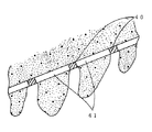
即ち、降雪があると、その底辺部は屋根からの熱及び自らの加重で一旦溶けて、それが再度の寒さで氷化することが多い。
この時、有孔カバーでは、その孔から雪が潜り込み、そこで溶けたものが再度氷結する等して固まり、丁度孔に杭を打ったのと同じ効果が得られるものと思料される(図12参照)。
そして、上記菱形の大きさが12×30.5〜34×76.2mmの範囲のものは、一旦溶けたものが再度氷化する際に杭状となるに適した表面張力を有するものと考えられる。
この結果、突起等を設けることなく、菱形の孔そのものに雪の落下防止効果をもたらすことができる。
【0033】
【発明の効果】
以上の如き構成及び作用に基づいて本発明は、
(a)熱膨張及び収縮を繰り返しても、両者間に介在する隙間によって吸収され、且つ、その隙間はコの字型のジョイントが両者間に跨って上から覆うので、丁度傘の役割を果たし、雨水漏水の問題を起こさない。
(b)内樋の施工が完了後、下側押さえ部材を長孔に沿って突出部の下側に潜らし、ボルトを締め付け方向に回転させると、ナット抑え片とナットとの関係からナットが固定され、ネジ部螺旋に従ってナットが上昇運動し、その上昇によって下側押さえ部材が上側押さえ部材との間で突出部を挟圧し、樋カバーを自動的且つ確実に固定することができる。
(c)12×30.5〜34×76.2mmの菱形に形成した樋カバーは、雪の底部融解に伴って杭打ち状となり雪の落下防止の効果を奏し、(d)更に、これらは組み合わされて多重的に効果を奏する。
【図面の簡単な説明】
【図1】本発明内樋の斜視図。
【図2】本発明ジョイント部を内樋に組み込んだ状態の一部部斜視図。
【図3】本発明内樋の縦断側面図。
【図4】 本発明内樋に樋カバーを装着した状態の縦断側面図。
【図5】樋カバーに上側押さえ部材と下側さえ部材とを組み込んだ状態の一部切欠分解斜視図。
【図6】抑え部材とナットとの関係を示す要部切欠側面図。
【図7】ナットの長径と短径の各態様を示す平面図。
【図8】上側押さえ部材と下側さえ部材とで樋カバーを装着する際の断面図で下側押さえ部材を移動させる前の状態を示す縦断側面図。
【図9】同上下側押さえ部材を左方に移動させた状態を示す縦断側面図。
【図10】下側押さえ部材で上方に締め付けた状態を示す縦断側面図。
【図11】菱形の樋カバーを拡大的に表した一部切欠正面図。
【図12】樋カバーが雪止め効果を発揮する状態を示す一部切欠縦断側面図。
【符号の説明】
10 受樋本体
11 底面
12 前壁
13 後壁
14,15 側壁
16 突出部
16a 葺板
16b 役物
17 カバー掛止部材
17a 上掛止片
17b 下掛止片
20 ジョイント部
21 胴体
22 当接片
23 ジョイント折曲片
30 ドレン
40 樋カバー
50 上側押さえ部材
51 押さえ部材上片
51a 屋根押止片
51b カバー挟片
51c 段部
51d ボルト用通孔
52 押さえ部材下片
52a 屋根押止片
52b カバー挟片
52c 段部
52d ボルト用通孔
60 下側押さえ部材
60a 屋根押さえ片
60b 押片
60c 通孔
60d ナット抑え片
60e 中間段部
70 ボルト
71 ナット[0001]
BACKGROUND OF THE INVENTION
This application consists of the invention of the 1st-3rd invention and these combination, and the 1st invention relates to the structure of the inside of a large roof of a general house, a school, a meeting place, a hospital, etc. The structure of the inner casing that prevents the expansion and contraction crack of the roofing material due to the difference in temperature and further has the effect of preventing slippage against snowfall, and then the second invention covers the open upper surface of the inner casing, The third aspect of the present invention relates to a cover structure having a simple structure and a snow-preventing effect. Furthermore, it is related with the invention which combined these 1st-3rd invention.
[0002]
[Prior art]
The inner wall is a wall that is arranged slightly above the roof (inside) from the eaves, compared to the general rain gutter where the eaves are provided.
The inner collar is generally formed by bending the tin material by extending it in the lateral direction with a U-shaped cross section with the upper side open, overlapping it at the joint, and nailing the joint, etc. I am letting.
And many of the moldings are on-site construction, and it relies on a method of forming a groove at a position where the inner lining of the roof should be provided and covering the waterproof sheet there.
In addition, it is desirable to apply a net cap because fallen leaves and the like may enter the inner casing and cause clogging. However, after forming the inner casing, a net body must be formed on site and processed into a cap. In other words, it must be an extremely troublesome task.
[0003]
However, according to the structure and method described above, (a) due to the difference in temperature between spring and summer and day and night, thermal expansion and contraction occur in the roof member made of a metal material such as tin, and a crack is likely to occur in the joint portion. This is a major cause of water leakage. (B) Machining the tin etc. on the site according to the relatively complicated shape of the inner gutter groove requires skill of skilled craftsmen, and the work efficiency is poor and the construction cost is high. There were disadvantages such as.
[0004]
In addition, the second problem is that the upper side of the inner casing is open, so fallen leaves and the like enter from there and cause clogging, so it is necessary to attach a cover that covers the upper surface. The cover had to be attached after the inner casing was attached, and the operation was extremely difficult.
[0005]
Third, when snow falls on the roof, a snow stop is required on the roof to prevent the fall. Conventionally, this snow stop has a protrusion on a part of the roof material to prevent sliding. Although it is general, it was structurally complex and the construction cost was high.
[0006]
[Problems to be solved by the invention]
The present invention has been made to eliminate these drawbacks. (A) The construction of an inner casing that does not cause rain leakage even if there is heat shrinkage due to temperature differences and can be assembled on the factory floor is developed. And (b) developing a structure of a kite cover that is easy to attach even after the construction of the inner kite, and (c) further developing a kite cover that itself has a snow stop effect, Furthermore, they try to derive a synergistic effect by combining them.
[0007]
[Means for Solving the Problems]
The invention of the first inner fence of the present application is that the inner body of the roof formed on the inner side of the eaves is provided with a receiving body that can store rainwater independently in a box shape with an open top surface along the inner cavity recess. A cross-sectionally U-shaped joint portion having a width dimension capable of absorbing the thermal expansion and contraction of the receiving body due to a difference in temperature between adjacent receiving books is straddled from the upper side, and part of the receiving body It is configured with a drain attached to guide the stored rainwater to the underground.
[0008]
In addition, the invention of the structure of the second saddle cover includes: (a) a perforated saddle cover that covers the upper part of the opened saddle receiving body; and (b) a roof pusher that is placed on the upper side of the protruding portion and presses the roof material from above. A pressing member upper piece comprising a stop piece, a cover holding piece that enters the inner hook side and sandwiches the upper cover from the upper side, a roof pressing piece placed on the upper side of the protruding portion, and an upper cover placed on the inner hook side An upper holding member comprising: a cover holding piece sandwiching the sheet from the lower side; and a holding member lower piece provided with a stepped portion corresponding to the thickness of the eaves cover in the middle of the holding member upper piece, and (c) a roofing material A roof pressing piece that holds this from the lower side along the lower side of the projecting portion, a pressing piece that supports this along the lower side of the roof holding piece, a nut holding piece that suppresses rotation of the nut, and the middle A lower pressing member comprising a step, and (d) the upper pressing member and the lower pressing member. The inner trough side members, and by arranging the bolts and nuts for fastening together bored long holes for the bolt holes and positioning.
[0009]
Combining the above first and second inventions, (a) In the inner lining of the roof formed inside the eaves, a receiving main body capable of storing rainwater independently in a box shape with an open top surface is used as an inner ridge recess. A joint portion having a U-shaped cross section having a width dimension capable of absorbing the thermal expansion and contraction of the receiving body due to a difference in temperature between the adjacent receiving books is straddled from the upper side, A drain that guides rainwater stored in a part of the main body to the basement is attached, and (b) (a) a perforated gutter cover that covers the upper part of the opened gutter body, and (b) placed on the upper side of the protrusion. A roof holding piece for holding the roof material from above, a cover holding piece that enters the inner fence side and sandwiches the fence cover from the upper side, and a roof holding piece placed on the upper side of the projecting portion, A cover sandwich piece that is placed on the inner collar side and sandwiches the collar cover from the lower side, and in the middle of the presser member upper piece An upper pressing member comprising a pressing member lower piece provided with a long step portion corresponding to the thickness of the bar; and (c) a roof pressing piece for pressing this from the lower side along the lower side of the protruding portion of the roof material; A lower pressing member comprising a pressing piece that supports the lower side of the roof pressing piece, a nut holding piece that inhibits rotation of the nut, and an intermediate step, and (d) the upper pressing member and the lower pressing member. On the inner flange side of the side pressing member, an invention of an inner flange is formed in which a bolt through hole and a long hole for position adjustment are formed and a bolt and nut for fastening are arranged.
[0010]
Further, the third cocoon cover invention is made of expanded metal formed in a rhombus, the rhombus is in the range of 12 × 30.5 to 34 × 76.2 mm, and the longitudinal direction of the rhombus is the vertical direction. Arranged to have a snow stop effect.
[0011]
Further, by combining the first invention, the second invention, and the third invention, (a) In the inner lining of the roof formed inside the eaves, rainwater can be stored independently in a box shape with an open top surface. And a joint portion having a U-shaped cross section having a width dimension capable of absorbing thermal expansion and contraction of the receiving body due to a temperature difference between adjacent receiving books. Stretched from the upper side, provided with a drain for guiding the rainwater stored in a part of the receiving body to the basement, (b) (a) a perforated fence cover covering the upper part of the opened receiving body, (B) a pressing member upper piece comprising a roof pressing piece that is placed on the upper side of the protruding portion and presses the roof material from above, a cover holding piece that enters the inner hook side and holds the hook cover from the upper side, In the middle of the roof holding piece placed on the upper side, the cover holding piece which is placed on the inner side and sandwiches the side cover from the lower side An upper pressing member comprising a pressing member lower piece provided with a stepped portion longer than the pressing member upper piece corresponding to the thickness of the eaves cover; and (c) the upper pressing member below the protruding portion of the roof material. A lower pressing member comprising a roof pressing piece pressed from the side, a pressing piece that supports the roof pressing piece along the lower side of the roof pressing piece, a nut holding piece that suppresses rotation of the nut, and an intermediate step portion; ) On the inner flange side of the upper pressing member and the lower pressing member, a bolt through hole and a long hole for position adjustment are formed and a bolt and nut for fastening are arranged, and (c) the The cover is made of expanded metal formed in a diamond shape, and the diamond shape is in the range of 12 × 30.5 to 34 × 76.2 mm, and the longitudinal direction of the diamond shape is the vertical and vertical direction to prevent snow. The invention of the structure of the inner casing characterized by having .
[0012]
DETAILED DESCRIPTION OF THE INVENTION
The embodiment of the first invention of the present application will be described. A wall body is formed on the front, rear, left, and right, and a
[0013]
First, the
In other words, the structure of the conventional bag that should flow down rainwater continuously in the lateral direction is abolished, the receiving body is divided into several independent boxes, and rainwater is stored and processed there. And
The front wall 12 and the
Further, it is desirable that the front wall 12 and the
[0014]
A
First, the
Then, a
[0015]
The
[0016]
The receiving
[0017]
Next, an embodiment of the second invention relating to the structure of the perforated rod cover for preventing the entry of fallen leaves and the like will be described with respect to the first invention related to the inner rod.
As shown in FIG. 3, the inner casing is provided with a receiving
At this time, a protruding
Moreover, although the
Since the upper side of the inner cage is open, fallen leaves and the like enter from there and cause clogging. Therefore, a
[0018]
Further, the
That is, as shown in FIG. 5, the upper pressing
At this time, the step portion 51c of the pressing member
[0019]
The lower pressing
Bolt holes are drilled on the inner flange side of the upper pressing
[0020]
As described above, the
First, as shown in FIGS. 6 and 7, for the nut 71, a different diameter nut having a different major axis (RA) and minor axis (RB) is used, and at least the use of a circular nut is eliminated.
When the distance from the center position of the nut 71 to the nut holding piece 60d is Lm,
RB <Lm <RA
A nut holding piece that satisfies the following conditions must be formed.
[0021]
A support piece 80 for receiving the eaves cover 40 is disposed on the upper side of the
Further, when the bent piece is bent outward, it is desirable that a hook-shaped hooking piece 12a is disposed along the front wall 12 and the roof member is bent to rain.
[0022]
Furthermore, the third cocoon cover invention is made of expanded metal formed in a rhombus, and the rhombus has a range of 12 × 30.5 to 34 × 76.2 mm (horizontal width × vertical width) as shown in FIG. It arrange | positions so that the longitudinal direction of a rhombus may become an up-down vertical direction.
[0023]
The inner casing of the present invention is capable of mass production of the receiving body and the joint portion based on a certain standard at the factory, and transports the receiving body and the like produced in advance by factory production to the construction site. And it puts it in the predetermined position of the roof formed in the recessed part for inner ridges of the receiving
[0024]
Thus, after arrange | positioning a receiving main body in parallel, the
The
Finally, the
[0025]
And when it rains in order to make it act as a kite, rain water flows down from the inclined roof, flows into the receptacle
[0026]
By the way, the receiving
However, in the inner collar of the present invention, when the collar extends in the longitudinal direction, the
In addition, the receiving
[0027]
After the construction of the inner casing is completed, the protruding
[0028]
Next, while adjusting the left and right positions along the long hole 60d of the lower pressing
The upper end of the eaves cover 40 is inserted between the upper hooking piece 17a and the lower hooking piece 17b of the projecting
As a result, the upper side of the
[0029]
Therefore, the head of the bolt 71 is rotated in the tightening direction with a rotary jig such as a rotary drill.
At this time, the nut holding piece 60d and the nut 71 are
RB <Lm <RA
Therefore, even if the nut 71 is driven in accordance with the rotation of the bolt 71, the longer diameter side of the nut 71 is engaged with the nut holding piece 60d, and the rotation is stopped.
[0030]
As a result of fixing the nut 71, the nut 71 moves upward according to the screw portion spiral engraved in the bolt 71 with the nut 71 as a fixing point, and is pushed by the upward movement, so that the entire lower pressing
Then, the roof pressing piece 60a formed at the end of the intermediate step portion 60e is pressed from the lower side of the striking plate 16a and the accessory 16b of the protruding
[0031]
Finally, to explain the third invention, the shape of the hole 41 of the eaves cover 40 includes a wire mesh system, a mesh system, a punching system steel plate, and the like.
However, when the effect on snowfall was tried, it was as shown in Table 1 below.
[Table 1]
Next, in the expanded metal rhombus hole 41, the degree of the snow stop effect was tested by changing the rhombus dimensions, and the results were as shown in the table below.
[Table 2]
In other words, when there is snow, the bottom of the snow melts once with the heat from the roof and its own load, and it often freezes in the cold again.
At this time, in the perforated cover, it is thought that the snow will dive from the hole, and the melted material solidifies there by freezing again, and the same effect is obtained as when the pile is just struck into the hole (see FIG. 12). ).
And when the size of the rhombus is in the range of 12 × 30.5 to 34 × 76.2 mm, it is considered that once melted, it has a surface tension suitable for becoming a stake when icing again. It is done.
As a result, the effect of preventing snow from falling can be provided to the diamond-shaped hole itself without providing a protrusion or the like.
[0033]
【The invention's effect】
Based on the above configuration and operation, the present invention provides:
(A) Even if thermal expansion and contraction are repeated, the gap is absorbed by the gap interposed between them, and the gap is covered with a U-shaped joint from above, so it acts just as an umbrella. Does not cause rainwater leakage problems.
(B) After the construction of the inner flange is completed, if the lower holding member is hidden under the protruding portion along the long hole and the bolt is rotated in the tightening direction, the nut will be released from the relationship between the nut holding piece and the nut. The nut is lifted according to the screw portion spiral, and the lower pressing member clamps the protruding portion with the upper pressing member by the lifting, so that the heel cover can be fixed automatically and reliably.
(C) The hail cover formed in a rhombus of 12 × 30.5 to 34 × 76.2 mm becomes a pile driving shape with the melting of the bottom of the snow, and has the effect of preventing the fall of the snow, (d) Combined to produce multiple effects.
[Brief description of the drawings]
FIG. 1 is a perspective view of an inner collar of the present invention.
FIG. 2 is a partial perspective view showing a state in which the joint portion of the present invention is incorporated in an inner collar.
FIG. 3 is a vertical side view of the inner collar of the present invention.
FIG. 4 is a vertical side view of a state in which the heel cover is attached to the inner heel of the present invention.
FIG. 5 is a partially cutaway exploded perspective view showing a state in which an upper pressing member and even a lower side member are incorporated in the heel cover.
FIG. 6 is a cutaway side view of a main part showing a relationship between a holding member and a nut.
FIG. 7 is a plan view showing each aspect of a long diameter and a short diameter of the nut.
FIG. 8 is a longitudinal sectional side view showing a state before the lower pressing member is moved in a cross-sectional view when the heel cover is mounted with the upper pressing member and the lower pressing member.
FIG. 9 is a longitudinal side view showing a state in which the upper and lower pressing members are moved leftward.
FIG. 10 is a longitudinal side view showing a state where the lower pressing member is tightened upward.
FIG. 11 is a partially cutaway front view showing an enlarged view of a rhombus ridge cover.
FIG. 12 is a partially cutaway longitudinal side view showing a state in which the eaves cover exhibits a snow stop effect.
[Explanation of symbols]
DESCRIPTION OF
Claims (2)
(b)突出部の上側に載って屋根材を上から押さえる屋根押止片と、内樋側に入って樋カバーを上側から挟み込むカバー挟片とから成る押さえ部材上片と、該突出部の上側に載った屋根押止片と、内樋側に載って樋カバーを下側から挟み込むカバー挟片と、その中間で上記押さえ部材上片より樋カバーの厚みに対応させて長い段部を設けた押さえ部材下片とから成る上側押さえ部材と、
(c)屋根材の突出部の下側に沿って、これを下側から押さえる屋根押さえ片と、上記屋根押さえ片の下側に沿ってこれを支える押片と、ナットの回転を抑止するナット抑え片と、中間段部とから成る下側押さえ部材と、
(d)上記上側押さえ部材及び下側押さえ部材の内樋側には、ボルト用通孔及び位置調整の為の長孔を穿設すると共に締結用のボルト・ナット配して成ることを特徴とする樋カバーの構造。(A) a perforated scissor cover that covers the upper part of the opened scissors body;
(B) a pressing member upper piece comprising a roof pressing piece that is placed on the upper side of the protruding portion and presses the roof material from above, a cover holding piece that enters the inner hook side and holds the hook cover from the upper side, A roof holding piece placed on the upper side, a cover holding piece that puts the eaves cover from the lower side on the inner eaves side, and a longer stepped portion corresponding to the thickness of the eaves cover than the upper piece of the holding member in the middle An upper pressing member comprising a pressing member lower piece;
(C) A roof pressing piece for holding the roof pressing member from the lower side along the lower side of the projecting portion of the roof material, a pressing piece for supporting the pressing member along the lower side of the roof pressing piece, and a nut for suppressing rotation of the nut. A lower holding member comprising a holding piece and an intermediate step,
(D) The inner pressing side of the upper pressing member and the lower pressing member is provided with a bolt hole and a long hole for position adjustment, and a bolt and nut for fastening are arranged. The structure of the heel cover.
(ロ)(a)開放された受樋本体の上部を覆う有孔樋カバーと、(b)突出部の上側に載って屋根材を上から押さえる屋根押止片と、内樋側に入って樋カバーを上側から挟み込むカバー挟片とから成る押さえ部材上片と、該突出部の上側に載った屋根押止片と、内樋側に載って樋カバーを下側から挟み込むカバー挟片と、その中間で上記押さえ部材上片より樋カバーの厚みに対応させて長い段部を設けた押さえ部材下片とから成る上側押さえ部材と、(c)屋根材の突出部の下側に沿って、これを下側から押さえる屋根押さえ片と、上記屋根押さえ片の下側に沿ってこれを支える押片と、ナットの回転を抑止するナット抑え片と、中間段部とから成る下側押さえ部材と、(d)上記上側押さえ部材及び下側押さえ部材の内樋側には、ボルト用通孔及び位置調整の為の長孔を穿設すると共に締結用のボルト・ナットを配し、
(ハ)該樋カバーが菱形に形成したエキスバンドメタルから成り、その菱形が12×30.5〜34×76.2mmの範囲で、且つ、菱形の長手方向が上下縦方向となるよう配設して雪止め効果を有すること、
を特徴とする内樋。(B) In the inner lining of the roof formed inside the eaves, a receiving body that can store rainwater independently in a box shape with an open top surface is provided continuously along the concave portion for the inner lining. A joint section with a U-shaped cross section having a width dimension capable of absorbing the thermal expansion and contraction of the receiving body due to the temperature difference between the main body is straddled from the upper side, and the rainwater stored in a part of the receiving body is underground With a drain leading to
(B) (a) A perforated rod cover that covers the upper part of the open receiving main body, (b) a roof pressing piece that sits on the upper side of the protruding portion and holds the roof material from above, and enters the inner rod side A pressing member upper piece composed of a cover sandwiching piece for sandwiching the eaves cover from the upper side, a roof pressing piece placed on the upper side of the projecting portion, a cover holding piece placed on the inner eaves side and sandwiching the eaves cover from the lower side, In the middle, an upper pressing member composed of a pressing member lower piece provided with a stepped portion corresponding to the thickness of the eaves cover from the pressing member upper piece, and (c) along the lower side of the protruding portion of the roof material, A lower pressing member comprising a roof pressing piece for pressing this from the lower side, a pressing piece for supporting the roof pressing piece along the lower side of the roof pressing piece, a nut holding piece for suppressing rotation of the nut, and an intermediate step portion; (D) On the inner flange side of the upper pressing member and the lower pressing member, It arranged bolts and nuts for fastening together bored long holes for holes and positioning,
(C) The heel cover is made of an expanded metal formed in a rhombus, and the rhombus is in a range of 12 × 30.5 to 34 × 76.2 mm, and the rhombus is arranged in the vertical direction in the vertical direction. And have a snow stop effect,
An inner shell characterized by
Priority Applications (1)
| Application Number | Priority Date | Filing Date | Title |
|---|---|---|---|
| JP2000258236A JP4189552B2 (en) | 2000-04-17 | 2000-08-28 | Structure of the inner collar and the collar cover |
Applications Claiming Priority (3)
| Application Number | Priority Date | Filing Date | Title |
|---|---|---|---|
| JP2000115734 | 2000-04-17 | ||
| JP2000-115734 | 2000-04-17 | ||
| JP2000258236A JP4189552B2 (en) | 2000-04-17 | 2000-08-28 | Structure of the inner collar and the collar cover |
Publications (2)
| Publication Number | Publication Date |
|---|---|
| JP2002004521A JP2002004521A (en) | 2002-01-09 |
| JP4189552B2 true JP4189552B2 (en) | 2008-12-03 |
Family
ID=26590263
Family Applications (1)
| Application Number | Title | Priority Date | Filing Date |
|---|---|---|---|
| JP2000258236A Expired - Fee Related JP4189552B2 (en) | 2000-04-17 | 2000-08-28 | Structure of the inner collar and the collar cover |
Country Status (1)
| Country | Link |
|---|---|
| JP (1) | JP4189552B2 (en) |
Families Citing this family (2)
| Publication number | Priority date | Publication date | Assignee | Title |
|---|---|---|---|---|
| CN111535520A (en) * | 2020-04-29 | 2020-08-14 | 浙江树人学院(浙江树人大学) | Metal roof gutter edge telescopic support and mounting method thereof |
| US20250137258A1 (en) * | 2022-02-08 | 2025-05-01 | Rain Harvesting Pty Ltd | Gutter mesh installation |
Family Cites Families (5)
| Publication number | Priority date | Publication date | Assignee | Title |
|---|---|---|---|---|
| JPS5724821Y2 (en) * | 1977-02-08 | 1982-05-29 | ||
| JPS63194079A (en) * | 1987-02-03 | 1988-08-11 | 株式会社 斎藤工務店 | Method for melting snow on roof |
| JPH0220651U (en) * | 1988-07-18 | 1990-02-09 | ||
| JPH02125120U (en) * | 1989-03-24 | 1990-10-16 | ||
| JP3034797B2 (en) * | 1996-05-22 | 2000-04-17 | 元旦ビューティ工業株式会社 | Roof structure with inner gutter |
-
2000
- 2000-08-28 JP JP2000258236A patent/JP4189552B2/en not_active Expired - Fee Related
Also Published As
| Publication number | Publication date |
|---|---|
| JP2002004521A (en) | 2002-01-09 |
Similar Documents
| Publication | Publication Date | Title |
|---|---|---|
| JPH11508339A (en) | Underlay elements for flat plate-like building elements | |
| JP4189552B2 (en) | Structure of the inner collar and the collar cover | |
| NL1012483C2 (en) | Gutter in gully of greenhouse roof has thermal insulation under rainwater channel to restrict condensation | |
| JPH0349214Y2 (en) | ||
| US20040231260A1 (en) | Under-deck grid-supported drainage system | |
| JP7171034B2 (en) | Eaves structure and its construction method | |
| JPH09137556A (en) | Method for construction for tile batten and tile, and roof structure | |
| JP3140835U (en) | Rain gutter with icicle prevention function | |
| JP4085226B2 (en) | The structure of the inner collar and the structure of the collar cover | |
| DE29701072U1 (en) | Lateral end element for flat roofs | |
| WO2004064496A1 (en) | Roof structure for greenhouses | |
| JPS5927445Y2 (en) | building roof | |
| JPS5921206Y2 (en) | Support metal fittings for ridge tiles, etc. | |
| JP3752666B2 (en) | Lifting device for concrete side groove and method for lifting and transporting concrete side groove using the same | |
| KR102184218B1 (en) | Installation system of vinyl house where ventilation skylight is installed | |
| JPH04327635A (en) | Discarded board for roofing material | |
| JPS6157751A (en) | Oblique flashing structure in traverse shingled roof | |
| JPS6328724Y2 (en) | ||
| JP3972215B2 (en) | Icicle prevention eaves | |
| JP2700763B2 (en) | Snow fall eaves | |
| JPS6117136Y2 (en) | ||
| JP2008138376A (en) | Cumulate snow drop prevention device for roof | |
| JPH0742783B2 (en) | Horizontal roof structure | |
| JPH0296046A (en) | Roof with solar energy collector | |
| JPS6036664Y2 (en) | roof structure |
Legal Events
| Date | Code | Title | Description |
|---|---|---|---|
| A621 | Written request for application examination |
Free format text: JAPANESE INTERMEDIATE CODE: A621 Effective date: 20050725 |
|
| A977 | Report on retrieval |
Free format text: JAPANESE INTERMEDIATE CODE: A971007 Effective date: 20070718 |
|
| A131 | Notification of reasons for refusal |
Free format text: JAPANESE INTERMEDIATE CODE: A131 Effective date: 20070724 |
|
| RD04 | Notification of resignation of power of attorney |
Free format text: JAPANESE INTERMEDIATE CODE: A7424 Effective date: 20070822 |
|
| A521 | Written amendment |
Free format text: JAPANESE INTERMEDIATE CODE: A523 Effective date: 20070821 |
|
| A521 | Written amendment |
Free format text: JAPANESE INTERMEDIATE CODE: A523 Effective date: 20070821 |
|
| A521 | Written amendment |
Free format text: JAPANESE INTERMEDIATE CODE: A523 Effective date: 20071112 |
|
| A131 | Notification of reasons for refusal |
Free format text: JAPANESE INTERMEDIATE CODE: A131 Effective date: 20080122 |
|
| A521 | Written amendment |
Free format text: JAPANESE INTERMEDIATE CODE: A523 Effective date: 20080205 |
|
| A131 | Notification of reasons for refusal |
Free format text: JAPANESE INTERMEDIATE CODE: A131 Effective date: 20080507 |
|
| A521 | Written amendment |
Free format text: JAPANESE INTERMEDIATE CODE: A523 Effective date: 20080630 |
|
| TRDD | Decision of grant or rejection written | ||
| A01 | Written decision to grant a patent or to grant a registration (utility model) |
Free format text: JAPANESE INTERMEDIATE CODE: A01 Effective date: 20080826 |
|
| A01 | Written decision to grant a patent or to grant a registration (utility model) |
Free format text: JAPANESE INTERMEDIATE CODE: A01 |
|
| A61 | First payment of annual fees (during grant procedure) |
Free format text: JAPANESE INTERMEDIATE CODE: A61 Effective date: 20080831 |
|
| FPAY | Renewal fee payment (event date is renewal date of database) |
Free format text: PAYMENT UNTIL: 20110926 Year of fee payment: 3 |
|
| R150 | Certificate of patent or registration of utility model |
Free format text: JAPANESE INTERMEDIATE CODE: R150 |
|
| FPAY | Renewal fee payment (event date is renewal date of database) |
Free format text: PAYMENT UNTIL: 20110926 Year of fee payment: 3 |
|
| FPAY | Renewal fee payment (event date is renewal date of database) |
Free format text: PAYMENT UNTIL: 20110926 Year of fee payment: 3 |
|
| FPAY | Renewal fee payment (event date is renewal date of database) |
Free format text: PAYMENT UNTIL: 20110926 Year of fee payment: 3 |
|
| FPAY | Renewal fee payment (event date is renewal date of database) |
Free format text: PAYMENT UNTIL: 20170926 Year of fee payment: 9 |
|
| LAPS | Cancellation because of no payment of annual fees |