JP4189236B2 - Cooking equipment top plate frame - Google Patents
Cooking equipment top plate frame Download PDFInfo
- Publication number
- JP4189236B2 JP4189236B2 JP2003052967A JP2003052967A JP4189236B2 JP 4189236 B2 JP4189236 B2 JP 4189236B2 JP 2003052967 A JP2003052967 A JP 2003052967A JP 2003052967 A JP2003052967 A JP 2003052967A JP 4189236 B2 JP4189236 B2 JP 4189236B2
- Authority
- JP
- Japan
- Prior art keywords
- frame
- top plate
- longitudinal direction
- frame material
- exhaust cover
- Prior art date
- Legal status (The legal status is an assumption and is not a legal conclusion. Google has not performed a legal analysis and makes no representation as to the accuracy of the status listed.)
- Expired - Fee Related
Links
Images


Description
【0001】
【発明の属する技術分野】
本発明は、ビルトインタイプのガスこんろ、電磁調理機器等の調理機器において、トッププレートの周縁に沿って取り付けるトッププレート枠の構造に関し、特にガラス板製のトッププレートの周縁に沿って取り付けるトッププレート枠の構造に関するものである。
【0002】
【従来の技術】
ガラス板のような材料にて形成せる矩形板状のトッププレートの周縁に矩形枠状のトッププレート枠が取り付けられる。この矩形枠状のトッププレート枠は金属にて形成されており、従来のトッププレート枠は次のように製造されている。
【0003】
その一例としては、前枠材と後枠材と両側の側枠材とを矩形状に配置し、これらの部材の端部を45°に切断して端面同士を突き合せ、接続金具等を介してスカーフジョイント方式で接続してある(例えば、特許文献1、特許文献2参照)。また他の例としては矩形枠状のトッププレート枠をプレス成形にて一体に形成することも行われている。
【0004】
【特許文献1】
特開平11−22981号公報
【特許文献2】
特開2002−13739号公報
【0005】
【発明が解決しようとする課題】
上記従来例の前者では、前枠材と後枠材と両側の側枠材との4つの部材を接続金具等を介して接続しているため、組み立てが複雑になるという問題があると共に接続に特別な部材を必要とするという問題があり、またコーナ部の継ぎ目に一体感がなくて外観が悪くなるという問題がある。また上記従来例の後者では、プレスで板を打ち抜いて成形するためにプレスするのに特別な金型を要して金型への投資コストがかかってコストアップになるという問題がある。
【0006】
本発明は上記の点に鑑みてなされたものであり、長尺の枠素材を曲げ加工することで容易に組み立てることができてコーナ部に継ぎ目がなくて外観よく形成できると共に安価に製造でき、また接続のための特別な部材を用いたりすることなく組み立てることができる調理機器のトッププレート枠を提供することを課題とするものである。
【0007】
【課題を解決するための手段】
上記課題を解決するための本発明の調理機器のトッププレート枠Aは、長尺の帯板状の枠素材1の長手方向と平行な一側縁に上面側に突出する凸条8を長手方向に亙って設け、枠素材1の凸条8のない他側縁から凸条8の手前まで至る折り曲げ溝2を枠素材1の長手方向に所定の間隔を隔てて形成すると共に折り曲げ溝2の部分で折り曲げ溝2がある側を内隅側として枠素材1を折り曲げて、前枠部3と両側の側枠部5と後枠部4とからなる矩形枠状に形成し、枠素材1の長手方向の両端同士を後枠部4の部分で突き合せ、排気カバー6を取り付けるための排気カバー受け7を後枠部4に沿って配置すると共に枠素材1の長手方向の両端の手前の部分を夫々排気カバー受け7に固着して枠素材1の長手方向の端部同士を連結したことを特徴とする。
【0008】
上記のように構成することにより、押し出し成形等にて形成せる枠素材1に折り曲げ溝2を形成し、この折り曲げ溝2の部分で曲げることで枠形状に曲げてトッププレート枠Aを組み立てることができる。これによりコーナ部は折り曲げ溝2にて折り曲げるだけでよく、組み立てが容易になると共に上記コーナ部は一体に繋がって外観よく形成できる。また一体にプレス成形したりするもののように特別な金型投資を要せず、コストダウンできる。またトッププレート枠Aの外周の上面に凸条8があるためにトッププレート9を嵌め込んだときトッププレート9の周囲の端面を凸条8にて支持できると共にトッププレート9の周囲の端面が見えないように外観よく仕舞うことができる。またトッププレート9の周囲の端面に沿って沿わせる凸条8を残して設けた折り曲げ溝2にてコーナ部を円滑に曲げることができる。
【0010】
更に、押し出し成形等にて形成せる枠素材1に折り曲げ溝2を形成し、この折り曲げ溝2の部分で曲げることで前枠部3と側枠部5と後枠部4とからなる矩形枠状に折り曲げると共に枠素材1の長手方向の端面同士を突き合せて排気カバー受け7に枠素材1の端部を固着することによりトッププレート枠Aを組み立てることができる。これにより四隅のコーナ部は折り曲げ溝2にて折り曲げるだけでよく、組み立てが容易になると共にコーナ部は一体に繋がって外観よく形成できる。また枠素材1の長手方向の端部同士は排気カバー6を受けるための排気カバー受け7にて接続することになり、特別な接続金具を用いたりする必要がなく、部品点数を削減することができると共にコストダウンを図ることができる。
【0011】
また枠素材1の長手方向の両端の手前の部分から排気カバー受け7にビスのような固着具16を打入して枠素材1を排気カバー受け7に固着したことを特徴とすることも好ましい。この場合、ビスのような固着具16を枠素材1から排気カバー受け7に打入するだけで枠素材1を排気カバー受け7に固着でき、枠素材1の長手方向の端部同士を連結する組み立てが容易にできる。
【0012】
またコーナ部で外隅部に位置する凸条8部分を平面から見て円弧状に曲げたことを特徴とすることも好ましい。この場合、コーナ部で外隅部に位置する凸条8部分を平面から円弧状に曲げるので凸条8部分を円滑に曲げることができると共にコーナ部分に丸みを持たせて外観よくできる。
【0013】
【発明の実施の形態】
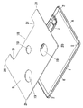
トッププレート枠Aを形成する枠素材1はアルミニウムのような材料にて押し出し成形することで形成されており、長手方向の全長に亙って同一断面になっている。この枠素材1は長尺の帯板状であり、この帯板状の枠素材1の両側の枠部材1の長手方向と平行な両側縁のうち一方の一側縁の上面側に長手方向に亙って断面直角三角形状の凸条8が設けられると共にこの一側縁の下面側に下方に突出する突縁10が長手方向に亙って設けられている。上記直角三角形状の凸条8は垂直面8aと斜面8bとを有している。
【0014】
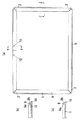
この枠素材1を矩形枠状に曲げることでトッププレート枠Aが組み立てられるのであるが、この枠部材1を折り曲げる部分には図2に示すように折り曲げ溝2が設けられるのであるが、枠素材1の両側の側縁のうち上記凸条8を設ける側と反対側である他側縁から凸条8のある側の一側縁に至る手前まで折り曲げ溝2を穿設してある。つまり、凸条8の部分を残すように穿設してある。この折り曲げ溝2は長手方向に所定の間隔を隔てて設けられ、折り曲げ溝2にて前枠部3と後枠部4と側枠部5に相当する部分に区画される。この折り曲げ溝2は略V字状の縦溝部2aと凸条8に沿う横溝部2bとで構成されている。
【0015】
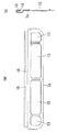
この枠素材1は凸条8がある部分が外側になるように折り曲げ溝2の部分で直角に折り曲げられ、図3に示すように矩形枠状に形成される。つまり、前枠部3に対して両側の側枠部5が直角に折り曲げられ、両側の側枠部5に対して後枠部4が直角に折り曲げられる。後枠部4の長手方向の中央となる部分では枠素材1の長手方向の端面同士が突き合せられる。折り曲げ溝2にて四隅のコーナ部を折り曲げるとき凸条8部分が円弧状になるように折り曲げられる。枠部材1の長手方向の端面同士は突き合せられるが、この端面の手前の部分には夫々取り付け孔12が穿孔されている。
【0016】
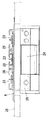
排気カバー6を受ける排気カバー受け7は図4に示すカバー受け本体7aと図5に示すような縁部材7bとをスポット溶接、かしめ等で一体に組み立てて形成されている。カバー受け本体7aは略矩形状の板材で形成されており、複数の排気孔13を設けてあり、一側縁から折り返した折り返し片14に一対のねじ孔15が形成されている。縁部材7bは全長に亙って突片部30を設けてある。
【0017】
図3のように枠素材1を矩形枠状に曲げた状態で、図6に示すように後枠部4に沿って排気カバー受け7が配置され、枠部材1の取り付け孔12と排気カバー受け7のねじ孔15とが対応させられ、ビスのような固着具16が取り付け孔12からねじ孔15に螺合され、後枠部4に排気カバー受け7が取り付けられると共に排気カバー受け7を介して枠部材1の端部同士が接合され、トッププレート枠Aが組み立てられる。
【0018】
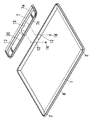
トッププレート9はガラス板にて略矩形板状に形成されており、トッププレート9の後部には排気口を設けるため略コ字状の切り欠き18が設けられており、またトッププレート9の適所にはこんろ用バーナを露出させるためのバーナ用開口19を穿孔してある。トッププレート9の四隅には円弧状の面取り20を設けてあり、切り欠き18の内隅にも円弧状の内隅部21が形成されている。このトッププレート9は図7に示すようにトッププレート枠Aの上方に配置され、凸条8や突片部30に囲まれる部分に嵌め込まれ、トッププレート9の外周の端面が凸条8の垂直面8aや突片部30に沿わせられる。このトッププレート9を取り付けるときには図8に示すように四隅で凸条8の垂直面8aの下部に対応する位置にスペーサ部材11が装着されると共に凸条8の垂直面8aや突片部30に沿ってシリコン接着剤のようなシール材29が塗布され、トッププレート9を嵌め込んだ状態でシール材29で接着されると共にこれらの間がシールされる。このようにして図9に示すようにトッププレート枠Aにトッププレート9が装着される。
【0019】
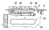
上記のような構造のトッププレート9を装着するガスこんろはビルトインタイプのものであり、図10乃至図12に示すようにケーシング22に複数個のこんろ用バーナ23やグリル24を組み込んでガスこんろ本体25が形成されており、台所キャビネットのカウンター26の開口からガスこんろ本体25をビルトインした状態でガスこんろ本体25の上面上に、トップレート枠Aを取り付けたトッププレート9が載設されている。このときトッププレート枠Aの下面側の突縁10の内側に沿って全周に当って装着したパッキン材27がカウンター26の上面に弾接させられる。このようにトッププレート9を載設した状態でこんろ用バーナ23がトッププレート9のバーナ用開口19から露出させられ、各こんろ用バーナ23に対応する位置でトッププレート9の上に五徳28が装着される。また排気カバー受け7には排気カバー6が被着される。
【0020】
なお、上記の実施の形態の説明では、ビルトインタイプのガスこんろのトッププレート9に装着するトッププレート枠Aの例について述べたが、ビルトインタイプの電磁調理機器のトッププレート枠にも用いることができる。
【0021】
また上記実施の形態の説明では、枠素材1の長手方向の両端同士を突き合せ、後枠部4の上に排気カバー受け7を重ね、枠素材1の長手方向の両端手前を排気カバー受け7に固着する例について述べが、枠素材1を折り曲げたとき、前枠部3と両側の側枠部5とからなる略コ字状に形成し、両側の側枠部5間に亙る長さの排気カバー受け7を両側の側枠部5の後部に架設し、側枠部5の後部と排気カバー受け7の端部とを固着して矩形状のトッププレート枠Aを組み立てるようにしてもよい。また排気カバー受け7に代えて操作部や表示部を備えた部材を略コ字状に曲げた枠部材1の端部間に架設してトッププレート枠Aを形成してもよい。
【0022】
また上記の実施の形態の説明では、枠素材1と排気カバー受け7とをビスのような固着具16で固着したが、溶接や引っ掛け係止等で固着してもよい。
【0023】
【発明の効果】
本発明の請求項1の発明は、長尺の帯板状の枠素材の長手方向と平行な一側縁に上面側に突出する凸条を長手方向に亙って設け、枠素材の凸条のない他側縁から凸条の手前まで至る折り曲げ溝を枠素材の長手方向に所定の間隔を隔てて形成すると共に折り曲げ溝の部分で折り曲げ溝がある側を内隅側として枠素材を折り曲げて枠形状に形成したので、押し出し成形等にて形成せる枠素材に折り曲げ溝を形成し、この折り曲げ溝の部分で曲げることで枠形状に曲げてトッププレート枠を組み立てることができるものであって、コーナ部は折り曲げ溝にて折り曲げるだけでよく、組み立てが容易になると共に上記コーナ部は一体に繋がって外観よく形成できるものであり、また一体にプレス成形したりするもののように特別な金型投資を要せず、コストダウンできるものであり、しかもトッププレート枠の外周の上面に凸条があるためにトッププレートを嵌め込んだときトッププレートの周囲の端面を凸条にて支持できると共にトッププレートの周囲の端面が見えないように外観よく仕舞うことができるものであり、さらにトッププレートの周囲の端面に沿って沿わせる凸条を残して設けた折り曲げ溝にてコーナ部を円滑に曲げることができるものである。
【0024】
また更に、折り曲げ溝で枠素材を折り曲げて前枠部と両側の側枠部と後枠部とからなる矩形枠状に形成し、枠素材の長手方向の両端同士を後枠部の部分で突き合せ、排気カバーを取り付けるための排気カバー受けを後枠部に沿って配置すると共に枠素材の長手方向の両端の手前の部分を夫々排気カバー受けに固着して枠素材の長手方向の端部同士を連結したので、押し出し成形等にて形成せる枠素材に折り曲げ溝を形成し、この折り曲げ溝の部分で曲げることで前枠部と側枠部と後枠部とからなる矩形枠状に折り曲げると共に枠素材の長手方向の端面同士を突き合せて排気カバー受けに枠素材の端部を固着することによりトッププレート枠を組み立てることができるものであって、四隅のコーナ部は折り曲げ溝にて折り曲げるだけでよく、組み立てが容易になると共にコーナ部は一体に繋がって外観よく形成できるものであり、また枠素材の長手方向の端部同士は排気カバーを受けるための排気カバー受けにて接続することになり、特別な接続金具を用いたりする必要がなく、部品点数を削減することができると共にコストダウンを図ることができるものである。
【0025】
また本発明の請求項2の発明は、請求項1において、枠素材の長手方向の両端の手前の部分から排気カバー受けにビスのような固着具を打入して枠素材を排気カバー受けに固着したので、ビスのような固着具を枠素材から排気カバー受けに打入するだけで枠素材を排気カバー受けに固着でき、枠素材の長手方向の端部同士を連結する組み立てが容易にできるものである。
【0026】
また本発明の請求項3の発明は、請求項1又は2において、コーナ部で外隅部に位置する凸条部分を平面から見て円弧状に曲げたので、コーナ部で凸条部分を円滑に曲げることができると共にコーナ部分に丸みを持たせて外観よくできるものである。
【図面の簡単な説明】
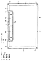
【図1】本発明のトッププレート枠の実施の形態の一例を示す平面図である。
【図2】同上の枠素材の展開状態を示し、(a)は平面図、(b)は(a)のX−X線断面図である。
【図3】同上の枠素材を曲げた状態を示し、(a)は平面図、(b)は(a)のY−Y線断面図、(c)は(a)のZ−Z線断面図である。
【図4】同上の排気カバー受け本体を示し、(a)は平面図、(b)は側面から見た拡大断面図である。
【図5】同上の縁部材を示し、(a)は平面図、(b)は側面から見た断面図である。
【図6】同上のトッププレート枠を組み立てる状態を説明する斜視図である。
【図7】同上のトッププレート枠にトッププレートを装着する状態を説明する斜視図である。
【図8】同上のトッププレート枠にスペーサ部材やシール材やパッキン材を取り付けた状態の四隅の部分を拡大した状態で(a)は平面図、(b)は(a)のW−W線で切断した断面図である。
【図9】同上のトッププレート枠にトッププレートを取り付け状態の斜視図である。
【図10】同上のトッププレートを取り付けた状態のガスこんろを示す平面図である。
【図11】図10の正面図である。
【図12】図11の側面図である。
【符号の説明】
A トッププレート枠
1 枠素材
2 折り曲げ溝
3 前枠部
4 後枠部
5 側枠部
6 排気カバー
7 排気カバー受け
8 凸条
9 トッププレート
16 固着具[0001]
BACKGROUND OF THE INVENTION
The present invention relates to a structure of a top plate frame that is attached along a peripheral edge of a top plate in a cooking appliance such as a built-in gas stove or an electromagnetic cooking appliance, and in particular, a top plate that is attached along the peripheral edge of a top plate made of a glass plate. It relates to the structure of the frame.
[0002]
[Prior art]
A rectangular frame-shaped top plate frame is attached to the periphery of a rectangular plate-shaped top plate formed of a material such as a glass plate. This rectangular frame-shaped top plate frame is formed of metal, and the conventional top plate frame is manufactured as follows.
[0003]
As an example, the front frame material, the rear frame material, and the side frame materials on both sides are arranged in a rectangular shape, the end portions of these members are cut at 45 °, the end surfaces are butted together, and a connection fitting or the like is interposed therebetween. Are connected by a scarf joint method (see, for example,
[0004]
[Patent Document 1]
JP-A-11-22981 [Patent Document 2]
Japanese Patent Laid-Open No. 2002-13739
[Problems to be solved by the invention]
In the former example of the conventional example, since the four members of the front frame member, the rear frame member, and the side frame members on both sides are connected via the connection fittings, there is a problem that the assembly becomes complicated and the connection is made. There is a problem that a special member is required, and there is a problem that the appearance is deteriorated because there is no sense of unity in the joint of the corner portion. In the latter case of the conventional example, there is a problem in that a special mold is required for stamping and molding a plate with a press, so that the investment cost for the mold is increased and the cost is increased.
[0006]
The present invention has been made in view of the above points, can be easily assembled by bending a long frame material, can be formed at a low cost and can be formed with a good appearance without a joint in the corner, It is another object of the present invention to provide a top plate frame of a cooking appliance that can be assembled without using a special member for connection.
[0007]
[Means for Solving the Problems]
The top plate frame A of the cooking appliance of the present invention for solving the above-mentioned problems is provided with a
[0008]
By constructing as described above, the
[0010]
Further, a
[0011]
Further, it is also preferable that the
[0012]
In addition, it is also preferable that the
[0013]
DETAILED DESCRIPTION OF THE INVENTION
The
[0014]
The top plate frame A is assembled by bending the
[0015]
This
[0016]
The
[0017]
In a state where the
[0018]
The
[0019]
The gas stove on which the
[0020]
In the above description of the embodiment, the example of the top plate frame A to be mounted on the
[0021]
In the description of the above embodiment, both ends in the longitudinal direction of the
[0022]
In the description of the above embodiment, the
[0023]
【The invention's effect】
According to the first aspect of the present invention, a ridge protruding in the longitudinal direction is provided on one side edge parallel to the longitudinal direction of a long belt-like frame material, extending in the longitudinal direction. Folding grooves from the other side edge where there is no gap to the front of the ridge are formed at predetermined intervals in the longitudinal direction of the frame material, and the frame material is bent with the side of the bending groove where the bending groove is located as the inner corner side. Since it was formed in a frame shape, it is possible to assemble a top plate frame by bending into a frame shape by forming a bending groove in a frame material that can be formed by extrusion molding, etc. The corners only need to be bent in the bending grooves, making the assembly easy, and the corners can be connected together and formed with a good appearance. Without needing Since the top plate frame has a ridge on the upper surface of the outer periphery of the top plate frame, when the top plate is fitted, the end surface around the top plate can be supported by the ridge and the end surface around the top plate can be seen. The corner portion can be smoothly bent by a bending groove provided with a protruding line extending along an end surface around the top plate.
[0024]
Furthermore, the frame material is bent by a bending groove to form a rectangular frame shape including a front frame portion, side frame portions on both sides, and a rear frame portion, and both ends in the longitudinal direction of the frame material are projected at the rear frame portion. In addition, an exhaust cover receiver for attaching the exhaust cover is disposed along the rear frame portion, and the front portions at both ends in the longitudinal direction of the frame material are fixed to the exhaust cover receiver, respectively, so that the longitudinal ends of the frame material are Since the frame is formed by extrusion molding or the like, a bending groove is formed in the frame material, and the bending material is bent at a portion of the bending groove to be bent into a rectangular frame shape including a front frame portion, a side frame portion, and a rear frame portion. The top plate frame can be assembled by abutting the end faces of the frame material in the longitudinal direction and fixing the end of the frame material to the exhaust cover receiver, and the corners at the four corners are simply folded at the folding grooves. Okay, pair It is easy to stand and the corners are connected together to form a good appearance, and the longitudinal ends of the frame material are connected by an exhaust cover receiver for receiving the exhaust cover. It is not necessary to use a simple connection fitting, and the number of parts can be reduced and the cost can be reduced.
[0025]
Further, the invention of
[0026]
Further, in the invention of
[Brief description of the drawings]
FIG. 1 is a plan view showing an example of an embodiment of a top plate frame of the present invention.
FIGS. 2A and 2B show a developed state of the frame material, in which FIG. 2A is a plan view and FIG. 2B is a cross-sectional view taken along line XX in FIG.
FIGS. 3A and 3B show a state in which the frame material is bent, wherein FIG. 3A is a plan view, FIG. 3B is a cross-sectional view along line YY in FIG. 3A, and FIG. 3C is a cross-sectional view along line ZZ in FIG. FIG.
4A and 4B show an exhaust cover receiving body according to the first embodiment, wherein FIG. 4A is a plan view and FIG. 4B is an enlarged cross-sectional view as viewed from the side.
5A and 5B show the edge member of the above, where FIG. 5A is a plan view, and FIG.
FIG. 6 is a perspective view illustrating a state in which the top plate frame is assembled.
FIG. 7 is a perspective view illustrating a state where the top plate is mounted on the top plate frame.
8A is a plan view, and FIG. 8B is a WW line in FIG. 8A, with the four corners of the top plate frame attached with a spacer member, sealing material, and packing material in an enlarged state. It is sectional drawing cut | disconnected by.
FIG. 9 is a perspective view showing a state in which the top plate is attached to the top plate frame.
FIG. 10 is a plan view showing the gas stove with the top plate attached thereto;
FIG. 11 is a front view of FIG. 10;
12 is a side view of FIG. 11. FIG.
[Explanation of symbols]
A
Claims (3)
Priority Applications (1)
| Application Number | Priority Date | Filing Date | Title |
|---|---|---|---|
| JP2003052967A JP4189236B2 (en) | 2003-02-28 | 2003-02-28 | Cooking equipment top plate frame |
Applications Claiming Priority (1)
| Application Number | Priority Date | Filing Date | Title |
|---|---|---|---|
| JP2003052967A JP4189236B2 (en) | 2003-02-28 | 2003-02-28 | Cooking equipment top plate frame |
Publications (2)
| Publication Number | Publication Date |
|---|---|
| JP2004263902A JP2004263902A (en) | 2004-09-24 |
| JP4189236B2 true JP4189236B2 (en) | 2008-12-03 |
Family
ID=33117706
Family Applications (1)
| Application Number | Title | Priority Date | Filing Date |
|---|---|---|---|
| JP2003052967A Expired - Fee Related JP4189236B2 (en) | 2003-02-28 | 2003-02-28 | Cooking equipment top plate frame |
Country Status (1)
| Country | Link |
|---|---|
| JP (1) | JP4189236B2 (en) |
Families Citing this family (4)
| Publication number | Priority date | Publication date | Assignee | Title |
|---|---|---|---|---|
| JP5213931B2 (en) * | 2010-10-12 | 2013-06-19 | リンナイ株式会社 | Gas stove |
| JP6856931B2 (en) * | 2017-04-18 | 2021-04-14 | 株式会社パロマ | Gas stove |
| JP6935074B2 (en) * | 2017-04-18 | 2021-09-15 | 株式会社パロマ | Gas stove and manufacturing method of gas stove |
| JP7142319B2 (en) * | 2018-04-13 | 2022-09-27 | パナソニックIpマネジメント株式会社 | induction cooker |
-
2003
- 2003-02-28 JP JP2003052967A patent/JP4189236B2/en not_active Expired - Fee Related
Also Published As
| Publication number | Publication date |
|---|---|
| JP2004263902A (en) | 2004-09-24 |
Similar Documents
| Publication | Publication Date | Title |
|---|---|---|
| US6374571B1 (en) | Insulation panel for cabinets containing air handling equipment | |
| JP3850705B2 (en) | Waterproof structure of display device | |
| JP2524061B2 (en) | Framework used for switch cabinet | |
| JP4189236B2 (en) | Cooking equipment top plate frame | |
| JPH09251570A (en) | Heat insulating panel assembly for automatic vending machine | |
| JPH11156134A (en) | Filter element | |
| JP4053213B2 (en) | Case frame structure | |
| JP5144140B2 (en) | Sash connection structure | |
| JP2002299848A (en) | Sheet metal housing structure of electronic equipment device | |
| JP3986366B2 (en) | Bonding structure at the corner of the partition | |
| JP4895180B2 (en) | Top plate structure of heating cooker | |
| JP4549319B2 (en) | Panel joint structure and partition wall | |
| JP4807540B2 (en) | Burner part attaching device and structure of burner part attaching device | |
| JPH0338398Y2 (en) | ||
| JP2731084B2 (en) | lighting equipment | |
| JPH07286771A (en) | Structure of box body for refrigerator | |
| JPS6033596Y2 (en) | Door body of high frequency heating equipment | |
| JPH1054185A (en) | Window frame device for fixed sash window | |
| JP2006090660A (en) | Fixing structure of top plate frame | |
| JP2004245525A (en) | Door body assembly structure for hinged double doors type refrigerator door | |
| JPH05741Y2 (en) | ||
| JPH0748951Y2 (en) | Area lattice | |
| JP3908979B2 (en) | Partition member and partition | |
| JPH0646243U (en) | Panel duct joint profile | |
| JP3096253B2 (en) | Panel set for table stove |
Legal Events
| Date | Code | Title | Description |
|---|---|---|---|
| A621 | Written request for application examination |
Free format text: JAPANESE INTERMEDIATE CODE: A621 Effective date: 20060206 |
|
| A131 | Notification of reasons for refusal |
Free format text: JAPANESE INTERMEDIATE CODE: A131 Effective date: 20080415 |
|
| A521 | Written amendment |
Free format text: JAPANESE INTERMEDIATE CODE: A523 Effective date: 20080616 |
|
| TRDD | Decision of grant or rejection written | ||
| A01 | Written decision to grant a patent or to grant a registration (utility model) |
Free format text: JAPANESE INTERMEDIATE CODE: A01 Effective date: 20080909 |
|
| A01 | Written decision to grant a patent or to grant a registration (utility model) |
Free format text: JAPANESE INTERMEDIATE CODE: A01 |
|
| A61 | First payment of annual fees (during grant procedure) |
Free format text: JAPANESE INTERMEDIATE CODE: A61 Effective date: 20080912 |
|
| R150 | Certificate of patent or registration of utility model |
Ref document number: 4189236 Country of ref document: JP Free format text: JAPANESE INTERMEDIATE CODE: R150 Free format text: JAPANESE INTERMEDIATE CODE: R150 |
|
| FPAY | Renewal fee payment (event date is renewal date of database) |
Free format text: PAYMENT UNTIL: 20110919 Year of fee payment: 3 |
|
| FPAY | Renewal fee payment (event date is renewal date of database) |
Free format text: PAYMENT UNTIL: 20110919 Year of fee payment: 3 |
|
| FPAY | Renewal fee payment (event date is renewal date of database) |
Free format text: PAYMENT UNTIL: 20120919 Year of fee payment: 4 |
|
| R250 | Receipt of annual fees |
Free format text: JAPANESE INTERMEDIATE CODE: R250 |
|
| FPAY | Renewal fee payment (event date is renewal date of database) |
Free format text: PAYMENT UNTIL: 20120919 Year of fee payment: 4 |
|
| FPAY | Renewal fee payment (event date is renewal date of database) |
Free format text: PAYMENT UNTIL: 20130919 Year of fee payment: 5 |
|
| R250 | Receipt of annual fees |
Free format text: JAPANESE INTERMEDIATE CODE: R250 |
|
| R250 | Receipt of annual fees |
Free format text: JAPANESE INTERMEDIATE CODE: R250 |
|
| R250 | Receipt of annual fees |
Free format text: JAPANESE INTERMEDIATE CODE: R250 |
|
| R250 | Receipt of annual fees |
Free format text: JAPANESE INTERMEDIATE CODE: R250 |
|
| R250 | Receipt of annual fees |
Free format text: JAPANESE INTERMEDIATE CODE: R250 |
|
| R250 | Receipt of annual fees |
Free format text: JAPANESE INTERMEDIATE CODE: R250 |
|
| R250 | Receipt of annual fees |
Free format text: JAPANESE INTERMEDIATE CODE: R250 |
|
| LAPS | Cancellation because of no payment of annual fees |