JP4187807B2 - Bag making machine - Google Patents
Bag making machine Download PDFInfo
- Publication number
- JP4187807B2 JP4187807B2 JP21100997A JP21100997A JP4187807B2 JP 4187807 B2 JP4187807 B2 JP 4187807B2 JP 21100997 A JP21100997 A JP 21100997A JP 21100997 A JP21100997 A JP 21100997A JP 4187807 B2 JP4187807 B2 JP 4187807B2
- Authority
- JP
- Japan
- Prior art keywords
- sheet
- straw
- sheets
- making machine
- along
- Prior art date
- Legal status (The legal status is an assumption and is not a legal conclusion. Google has not performed a legal analysis and makes no representation as to the accuracy of the status listed.)
- Expired - Fee Related
Links
Images

Landscapes
- Making Paper Articles (AREA)
Description
【0001】
【発明の属する技術分野】
本発明は、樹脂製の袋体を製造する製袋機に係り、特に、内容物吐出用のストローが設けられた袋体を製造するための製袋機に関する。
【0002】
【従来の技術】
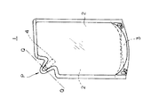
この種の袋体の例を図12に示す。この袋体1は、各種液体の容器として使用されるもので、樹脂製のシート2の端部同士をヒートシールにて張り合わせるとともに、シート2の下端に、底部となる樹脂製のシート3をヒートシールにて張り合わせることにより、袋体1内にシート2,3で囲まれた空間が形成され、かつ袋体1の自立性が付与されている。
【0003】
更に、袋体1の上端近傍には、上記空間と連通する突起Pが形成され、この突起P内には、円筒状をなすストロー4が、その側面をシート2にヒートシールにて密着させた状態で支持されている。そして、ストロー4の外側を覆うシール部を図12中Q−Q線で示す位置にて切断することにより、上記空間内に貯留された液体を、ストロー4を介して吐出可能となっている。
【0004】
また、上記構成を有する袋体1は、以下の(1)〜(4)の工程を経て製造される。
(1)帯状をなす上下二枚のシート(袋体1のシート2に相当)をその長手方向に沿って搬送しつつ、これらシート間に、帯状をなす第二のシート(袋体1のシート3に相当)をその長手方向に沿って設置する。
(2)上記シートに、このシートをプレフォームしてなる凹部を、シートの搬送方向に沿って所定間隔で形成した後、下方に位置するシートの凹部内に、ストロー4を設置する。
(3)シート同士をヒートシールするとともに、シートとストロー4及び第二のシートとをヒートシールする。
(4)シートを袋体1の外形に合わせて成形した後、所定間隔で切断する。この場合、袋体1のコーナー部におけるオニ歯部の形成を防止するため、成形後の上記シートは、所定幅のドブ(切除部分)を介して切断される。
【0005】
なお、上記工程を経て製造された袋体1では、上端に開口が形成されている。この開口は袋体1内への液体の注入口として用いられるもので、液体の注入後、ヒートシールにより閉鎖される。
【0006】
【発明が解決しようとする課題】
しかしながら、上記工程による袋体1の製造に際しては、例えば以下に示すような問題があった。
(イ)シートとストロー4とのシールが不十分である。
(ロ)シートとストロー4とのシール後におけるシール用金型とシートとの剥離性が低く、その結果、シートとストロー4とのシール部が剥離する場合があり、かつ熱間剥離による上記シール部の剥離も増長される。
(ハ)凹部内へのストロー4の設置に際し、ストロー4を凹部の上方約15cmに位置する供給ゲートから自由落下させて供給しているため、凹部内におけるストロー4の設置位置にばらつきが生じる。
(ニ)上下二枚のシート間の搬送方向及び巾方向に沿った位置ずれ(特に印刷ずれ)を防止するため、上下二枚のシートの位置を、手動により、約10分に1回程度の割合で修正する必要がある。
(ホ)シートを袋体1の外形に合わせて成形するカッタの位置を、シートの巾方向に沿った蛇行に対応して、手動により、約10分に1回程度の割合で修正する必要がある。
(ヘ)成形後のシートの切断は、シート同士のシール及びシートとストロー4とのシールに伴う搬送停止と同期して行われるが、搬送停止1回あたり1箇所しか切断できないため、ドブを除去するためには2回の搬送停止が必要となり、袋体1の製造速度が遅くなる。
本発明は上記事情に鑑みてなされたもので、袋体1を製造する製袋機における、上記(イ)ないし(ヘ)を始めとする諸問題の解消をその目的としている。
【0007】
【課題を解決するための手段】
本発明は、帯状をなす上下二枚の第一のシートをその長手方向に沿って搬送しつつ、
これら第一のシート間に、帯状をなす第二のシートをその搬送方向に沿って設置し、かつ前記第一のシートのうち下方に位置するシートをプレフォームして、前記第一のシートの搬送方向に沿って所定間隔で凹部を形成した後、該凹部内に円筒状をなすストローを前記第一のシートの搬送方向に沿って所定間隔で設置する工程と、
前記第一のシート同士をシールし、かつ前記第一のシートと前記ストロー及び前記第二のシートとをシールすることにより、前記第一のシート及び第二のシートで囲まれた空間を前記第一のシートの長手方向に沿って所定間隔で形成する工程と、
前記第一のシートを、袋体の外形に合わせて前記所定間隔で成形、切断する工程とを順次行うことにより、
前記第二のシートを底面とし、袋体の上端近傍に前記空間と連通する突起が形成され、この突起内には、上記ストローが、その側面を前記第一のシートにヒートシールにて密着させた状態で支持され、かつ前記空間に貯留される内容物を前記ストローから吐出可能な袋体を製造する製袋機であって、
前記下方に位置する第一のシートの前記凹部への前記ストローの設置およびシールに先立ち、ストロー設置部位となる前記下方に位置する第一のシートの前記凹部を余熱するヒータと、このヒータによって余熱されている前記凹部内に前記ストローをポイントシールにより仮止めするポイントシール装置と、前記凹部内に仮止めされた前記ストローの側面を前記上下二枚の第一のシートとシールする金型とを具備することを特徴としている。
【0008】
ここで、前記上下二枚の第一のシートと前記ストローとのシールに用いられる前記金型の前記シートとの接触面に、フッ素樹脂加工が施されていることが望ましい。
【0009】
また、前記シートへの前記ストローの設置に際しては、前記ストローを上方から真空吸引し、吸引した前記ストローを、前記下方に位置する第一のシートの、前記ストロー設置部位の直上まで搬送した後、吸引を解除して前記ストローを落下させることにより、前記ストローを前記ストロー設置部位に設置する設置手段を用いることが望ましい。
【0010】
また、上下二枚のシート間の搬送方向及び巾方向に沿った位置ずれを防止するため、前記第一のシート同士のシールに先立ち前記第一のシート同士が重ね合わされるよう前記シートの搬送方向を変える合わせロールと、前記第一のシート間の前記搬送方向に沿った位置ずれを検出する第一の検出手段と、第一の検出手段の検出結果に基づき、前記搬送方向に沿った位置ずれがなくなるまで前記合わせロールを上下に移動させる第一の移動手段と、前記第一のシート間の巾方向に沿った位置ずれを検出する第二の検出手段と、第二の検出手段の検出結果に基づき、前記巾方向に沿った位置ずれがなくなるまで前記合わせロールを前記巾方向に沿って移動させる第二の移動手段とを設置することが望ましい。
【0011】
また、前記第一のシートを切断する際、前記第一のシートの巾方向に沿った蛇行に対応するため、前記第一のシートの巾方向に沿った蛇行を検出する第三の検出手段と、第三の検出手段における検出結果に基づき、前記第一のシートを前記袋体の外形に合わせて切断する第一のカッタを前記蛇行と同期して前記巾方向に沿って移動させる第三の移動手段とを設置することが望ましい。
【0012】
なお、前記第一ないし第三の検出手段には、例えば前記第一のシートの図柄または前記第一のシートの巾方向両端部の位置を検出する光学センサが使用され、かつ前記第一ないし第三の移動手段には、前記合わせロールを上下または前記巾方向に沿ってそれぞれ移動させるか、あるいは前記第一のカッタを前記巾方向に沿って移動させるサーボモータが使用される。
【0013】
一方、前記袋体の外形に合せて成形後の前記第一のシートを前記所定間隔で切断する第二のカッタには、前記第一のシートを挟んで対向する上下一対のギロチンカッタを用いることが望ましい。この場合、前記ギロチンカッタは、前記第一および第二のシートのシート同士のシールに伴うこれらシートの搬送停止と同期し、この搬送停止1回あたり前記第一のシートを所定幅のドブを介して2回切断する。
【0014】
【発明の実施の形態】
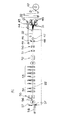
以下、図面に基づき、本発明の実施形態について説明する。本発明に係る製袋機41の概略構成及び一部を図1及び図4に、また、製袋機41による袋体1の製造手順を図2、図3及び図5ないし図11にそれぞれ示す。図1中符号42は、袋体1のシート2となる原反21が巻回されたリールで、このリール42から供給された原反21は、カッタ(図示せず。)にて帯状をなす同一巾の第一のシート22(以下、単に「シート22」という場合がある。)に切断された後、上下に重ね合わされた状態で、自らの長手方向に沿って図中左方に搬送される。
【0015】
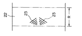
符号43はヒータで、搬送されたシート22は、このヒータ43により、その長手方向に沿って、袋体1の巾と同一間隔(図2中符号R)で余熱され、その結果、シート22に、図2に符号23で示すような一対の余熱部が上記間隔Rで形成される。特に、この製袋機41は、シート22の巾方向に沿った一対の袋体1を、その上端同士を連結した状態で同時に製造するものであるため、余熱部23は、シート22の巾方向中央部に、シート22の巾方向に対称をなすよう形成される。
【0016】
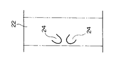
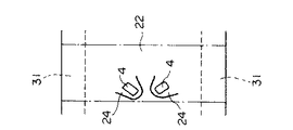
符号44は余熱部23を局所的にプレフォームするフォーミング装置で、フォーミング装置44によるプレフォームの結果、余熱部23に、図3に符号24で示すような一対の凹部が形成される。ここで、凹部24は、上方側のシート22では下方向きに、下方側のシート22では上方向きにそれぞれ形成される。また、凹部24の形成後、下方側のシート22は一旦下方に搬送された後、再度上方側のシート22と平行に搬送され、その結果、上方側のシート22と下方側のシート22との間には、所定幅の隙間Sが形成される。
【0017】
符号45は左右一対のリールで、これらリール45には、袋体1のシート3となる帯状のシート(第二のシート)31がそれぞれ巻回されている。リール45から供給されたシート31は、その巾方向中央にて折り返された後、折り返しの結果形成された稜辺部が互いに対向し、かつその巾方向両端部がそれぞれシート22の巾方向両端部と重なるよう、下方側のシート22上に水平に配設される。図5ないし図10中に点線で示す部分が、シート22に対するシート31の配設位置である。また、シート22上に配設されたシート31は、シート22とともに図中左方に搬送される。
【0018】
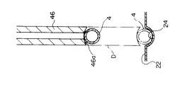
符号46は、隙間Sに配設され、ストロー4を下方側のシート22に形成された凹部24(ストロー設置部位)内に設置する設置手段である。この設置手段46は、図4に示すように上下に延設された中空円筒状をなす部材で、その軸線に沿って上下動可能とされ、かつ上端には真空ポンプ(図示せず。)が連結されている。また、設置手段46の下端には吸引口46aが開口し、かつ吸引口46aの端面は、ストロー4の表面より大きな曲率で上方に向け凸なるU字状をなしている。
【0019】
ストロー4の設置に際しては、まず、設置手段46を最上位置まで引き上げ、ストロー供給手段(図示せず。)から供給されたストロー4を吸引口にて上方から真空吸引する。ここで、吸引口46aの端面が上方に向け凸なるU字状をなしているため、ストロー4は常時吸引口46aの最底部、すなわち吸引口46aの中央部に吸引支持される。そして、図4中符号Dで示すように、ストロー4が凹部24の直上に到達するまで設置手段46を下降させた後、吸引を解除してストロー4を凹部24内に落とし込む。
【0020】
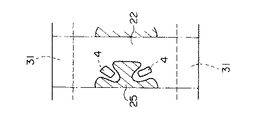
また、符号47は、ストロー4の設置に先立ち凹部24を余熱するヒータ、符号48は、設置されたストロー4をポイントシールにより凹部24内に仮止めするポイントシール装置である。凹部24へのストロー4の設置状況を図5に示す。
【0021】
符号49は、隙間Sを介して搬送されていた上下各シート22の対向面同士が再度重ね合わさるよう、上方側のシート22の搬送方向を下方に偏向させる合わせロールで、この合わせロール49は、サーボモータ(第一及び第二の移動手段、図示せず。)により、上下及びシート22の巾方向に移動可能とされている。また、上記サーボモータの作動は、上下各シート22の図柄及び巾方向両端部の位置をそれぞれ検出する光学センサ(第一及び第二のの検出手段、図示せず。)と、これら光学センサの出力値に基づき、上下各シート22の図柄及び巾方向両端部の位置をそれぞれ比較して、上下の各シート22間の搬送方向及び巾方向に沿った位置ずれを検出する制御手段(図示せず。)により制御されている。
【0022】
すなわち、本発明の製袋機41の場合、上記光学センサの検出結果に基づき上記サーボモータを作動させ、上下各シート22間の搬送方向及び巾方向に沿った位置ずれがなくなるまで、合わせロール49を上下及び/またはシート22の巾方向に移動させることにより、上下各シート22間の位置ずれを防止している。また、上記光学センサには、例えばCCDカメラ等が使用される。また、合わせロール49を経て下方に搬送された上方側のシート22は、下方側のシート22の搬送方向に沿って再度重ね合わされる。
【0023】
符号50は、シート22とストロー4とをシールする金型で、この金型50はアルミニウム製とされ、かつ本発明の製袋機41の場合、金型50のシート22との接触面には、この種の製袋機で多用されるサンドブラスト加工に換え、フッ素樹脂加工が施されている。そして、シート22のうちストロー4が介在する部位を金型50にて上下から挟むことにより、この部位に図6中符号25で示すようなシール部が形成され、その結果、ストロー4の側面とシート22とがシールされて、ストロー4がシート22に固定される。
【0024】
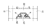
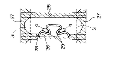
符号51は冷却金型で、この冷却金型51はアルミニウム製とされ、かつ本発明の製袋機41の場合、冷却金型51のシール部25との接触面には、この種の製袋機で多用される#60のサンドブラスト加工に換え、より粗い#40のサンドブラスト加工が施されている。そして、金型50により形成されたシール部25を冷却金型51にて上下から挟むことにより、シール部25の内側に、図7中符号26で示すようなシール部が形成される。また、本発明の製袋機41の場合、冷却金型51におけるシール圧力は、10kg/cm2以上となっている。
【0025】
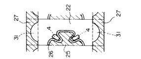
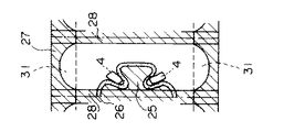
符号52は、シール部25,26形成後のシート22とシート31との重合部を、シート22の巾方向両端部にて挟む金型である。そして、上記重合部を金型52にて上下から挟むことにより、上記重合部に、図8中符号27で示すようなシール部が袋体1の巾と同一ピッチで形成され、シート22の巾方向両端部がシート31により閉鎖される。
【0026】
符号53は、シール部25,26,27形成後のシート22をその巾方向に沿って袋体1の巾と同一間隔で挟むシール装置である。そして、シート22をシール装置53にて上下から挟むことにより、シート22に、図9中符号28で示すようなシール部が、シート22の巾方向に沿って袋体1の巾と同一間隔で形成される。更に、符号54は、シール部28を上下から挟み、シール部28を冷却する冷却装置である。
【0027】
符号55は、シール部25を打ち抜き、シール部25,26,27,28形成後のシート22に、図10中符号29で示すような突起(袋体1の突起Pに相当する部分)を形成させるカッタ(第一のカッタ)、符号56は、シール部27の両端部をカットし、袋体1のコーナー部を整形するカッタ(第一のカッタ)である。
【0028】
また、これらカッタ55,56は、シート22の巾方向両端部の位置を検出し、シート22の巾方向に沿った蛇行を検知する光学センサ(第三の検出手段、図示せず。)と、この光学センサの出力結果に基づき、カッタ55,56を上記蛇行と同期して左右に移動させるサーボモータ(第三の移動手段、図示せず。)とを備えている。
【0029】
すなわち、本発明の製袋機41の場合、上記光学センサの検出結果に基づき上記サーボモータを作動させ、カッタ55,56を、上記蛇行と同期して左右に移動させることにより、上記蛇行に伴うシート22の巾方向のずれに起因する、シート22に対するカッタ55,56の切断位置のずれを防止している。また、上記光学センサには、例えばCCDカメラ等が使用される。
【0030】
符号57は、シール部28のうち、シート22の長手方向中央部を、シート22の巾方向に沿って切断するカッタ(第二のカッタ)である。特に、本発明の製袋機41の場合、カッタ57には、従来、この種の製袋機で多用される、平行な2枚刃と、これら2枚刃と対向する1枚刃との噛合によるものに換え、上下一対のギロチンカッタが使用されている。また、このカッタ57は、サーボモータにより、シート22の搬送方向に沿って例えば1mm単位で移動可能とされている。
【0031】
シート22の成形及び切断は、従来の製袋機と同様、シート22,31同士のシール及びシート22とストロー4とのシールに伴う搬送停止と同期して行われる。また、シート22は、袋体1のコーナー部におけるオニ歯部の形成を防止するため、所定幅のドブを介して切断するが、本発明の場合、カッタ57が、上記シールに伴う搬送停止と同期し、かつシート22の搬送方向に沿って移動しつつ、搬送停止1回あたりシート22を所定幅のドブを介して2回切断する。すなわち、本発明の製袋機では、1回の搬送停止でドブの切除が完了する。
【0032】
カッタ57による切断の結果、図11に示すような、上端部同士が連結された袋体1が形成される。また、符号58は、形成された袋体1を搬送するコンベヤで、コンベヤ58上に排出された袋体1の上端部を図11中T−T線で示す位置にて切断することにより、上端が開口した袋体1が完成する。
【0033】
このように、本発明の製袋機41は、上記した符号42〜57で示す部材を具備し、その結果、自らの長手方向に沿って図中左方に搬送されるシート22に、これら符号42〜57で示す部材を用いて上記図2、図3及び図5ないし図10に示す加工を順次施すことにより、上記図11に示す袋体1が製造される。
【0034】
特に、本発明の製袋機41では、ストロー4の設置に先立ちシート22に形成された凹部24を余熱するヒータ47を備えている。その結果、凹部24が軟化してストロー4に接着しやすくなり、シート22とストロー4とのシール性が向上する。
【0035】
また、金型50のシート22との接触面に、従来のサンドブラスト加工に換え、フッ素樹脂加工を施したため、シート22とストロー4とのシール後における金型50からのシート22の剥離性が相対的に向上し、その結果、金型50に対するシート22の不要な固着と、それに伴うシート22とストロー4とのシール部位の剥離が防止される。
【0036】
更に、冷却金型51のシール部25との接触面に施されるサンドブラスト加工の粗さを、従来より粗い#40としたため、熱間剥離によるシール部25の剥離が低下する。しかも、冷却金型51におけるシール圧力を10kg/cm2以上としたため、熱間剥離によるシール部25の剥離が更に低下する。
【0037】
また、凹部24内へのストロー4の設置に際し、ストロー4を吸引口46aにて上方から真空吸引し、ストロー4が凹部24の直上に到達するまで下降した後、吸引を解除してストロー4を凹部24内に落下させる設置手段46を用いたため、ストロー4を凹部24に対し15cmも自由落下させる従来の方法に比べ、凹部24内におけるストロー4の設置位置が正確となる。
【0038】
また、光学センサと、この光学センサの出力結果に基づき作動するサーボモータとを用いて、シート22間の搬送方向及び巾方向に沿った位置ずれや、シート22の巾方向に沿った蛇行に伴うシート22に対するカッタ55,56の切断位置のずれを防止しているため、上記位置ずれ防止作業の自動化(無人化)が可能となる。
【0039】
また、成形後のシート22を切断するカッタ57が、シート22の搬送方向に沿って移動しつつ、搬送停止1回あたりシート22を所定幅のドブを介して2回切断し、その結果、1回の搬送停止でドブの切除が完了するため、ドブの切除に2回の搬送停止を要していた従来の製袋機に比べ、袋体1の製造速度が2倍となる。更に、カッタ57に上下一対のギロチンカッタを用いたため、従来の2枚刃と1枚刃との噛合によるものに比べ、カッタ57の寿命が約3〜5倍程度向上する他、カッタ57の交換が容易で、しかも交換に伴うカッタ57の設置誤差が低下するという効果が得られる。カッタ57の刃先精度が向上し、ドブ巾が縮小するため、生産コストが低下するという効果もある。
【0040】
一方、符号42〜57に示す部材にそれぞれサーボモータを取り付け、これらサーボモータをシート22の送り速度に準拠して一元管理することも可能である。この場合には、シート22の送り速度が変化した場合でも、符号42〜57に示す部材の動作速度を上記送り速度に追従して変化させることが可能で、その結果、常時安定した袋体1の製造が可能となる。
【0041】
【発明の効果】
以上説明した通り、本発明の製袋機によれば、ストローの設置に先立ち第一のシートに形成された凹部を余熱するヒータを備えているため、凹部が軟化してストローに接着しやすくなり、第一のシートとストローとのシール性が向上するという効果が得られる。
【0042】
また、第一のシートとストローとをシールする金型のシートとの接触面にフッ素樹脂加工を施したため、第一のシートとストローとのシール後における金型からの第一のシートの剥離性が相対的に向上し、その結果、金型に対する第一のシートの不要な固着と、それに伴う第一のシートとストローとのシール部位の剥離が防止される。
【0043】
また、第一のシートに形成された凹部内へのストローの設置に際し、ストローを吸引口にて上方から真空吸引し、ストローが凹部の直上に到達するまで下降した後、吸引を解除してストローを凹部内に落下させる設置手段を用いたため、凹部内におけるストローの設置位置が正確となる。
【0044】
更に、光学センサと、この光学センサの出力結果に基づき作動するサーボモータとを用いて、第一のシート間の搬送方向及び巾方向に沿った位置ずれや、第一のシートの巾方向に沿った蛇行に伴う第一のシートに対するカッタの切断位置のずれを防止しているため、上記位置ずれ防止作業の自動化(無人化)が可能となる。
【0045】
更にまた、成形後の第一のシートを切断する第二のカッタが、第一のシートの搬送方向に沿って移動しつつ、搬送停止1回あたり第一のシートを所定幅のドブを介して2回切断し、その結果、1回の搬送停止でドブの切除が完了するため、ドブの切除に2回の搬送停止を要していた従来の製袋機に比べ、袋体1の製造速度が2倍となる。
【図面の簡単な説明】
【図1】 本発明の製袋機の概略構成を示す製袋機の側面図である。
【図2】 本発明の製袋機による袋体の製造工程を示す上面図である。
【図3】 本発明の製袋機による袋体の製造工程を示す上面図である。
【図4】 本発明の製袋機における設置手段の構造の例を示す断面図である。
【図5】 本発明の製袋機による袋体の製造工程を示す上面図である。
【図6】 本発明の製袋機による袋体の製造工程を示す上面図である。
【図7】 本発明の製袋機による袋体の製造工程を示す上面図である。
【図8】 本発明の製袋機による袋体の製造工程を示す上面図である。
【図9】 本発明の製袋機による袋体の製造工程を示す上面図である。
【図10】 本発明の製袋機による袋体の製造工程を示す上面図である。
【図11】 本発明の製袋機による袋体の製造工程を示す上面図である。
【図12】 袋体の構造を示す上方斜視図である。
【符号の説明】
1 袋体
4 ストロー
22 シート(第一のシート)
24 凹部(ストロー設置部位)
31 シート(第二のシート)
41 製袋機
46 設置手段
47 ヒータ
48 ポイントシール装置
49 合わせロール
50 金型
55,56 カッタ(第一のカッタ)
57 カッタ(第二のカッタ)[0001]
BACKGROUND OF THE INVENTION
The present invention relates to a bag making machine for producing a resin bag, and more particularly to a bag making machine for producing a bag provided with a straw for discharging contents.
[0002]
[Prior art]
An example of this type of bag is shown in FIG. The
[0003]
Further, a protrusion P communicating with the space is formed in the vicinity of the upper end of the
[0004]
Moreover, the
(1) A belt-like second sheet (sheet of bag 1) is conveyed between the two upper and lower sheets (corresponding to sheet 2 of bag 1) in the longitudinal direction while transporting along the longitudinal direction. 3) is installed along its longitudinal direction.
(2) After forming recesses formed by preforming the sheet on the sheet at predetermined intervals along the sheet conveyance direction, the
(3) While heat-sealing the sheets, the sheet, the
(4) After the sheet is formed according to the outer shape of the
[0005]
In addition, in the
[0006]
[Problems to be solved by the invention]
However, when manufacturing the
(B) The seal between the seat and the
(B) The sealing mold and the sheet after the sealing between the sheet and the
(C) When the
(D) In order to prevent misalignment (especially printing misalignment) along the conveying direction and the width direction between the upper and lower two sheets, the position of the upper and lower two sheets is manually set to about once every 10 minutes. It is necessary to correct in proportion.
(E) It is necessary to manually correct the position of the cutter for forming the sheet according to the outer shape of the
(F) Cutting of the sheet after forming is performed in synchronization with the conveyance stop associated with the seal between the sheets and the seal between the sheet and the
The present invention has been made in view of the above circumstances, and an object of the present invention is to solve various problems including the above (a) to (f) in the bag making machine for manufacturing the
[0007]
[Means for Solving the Problems]
While the present invention conveys the first sheet of the upper and lower two sheets that form a belt shape along its longitudinal direction,
Between these first sheets, a second sheet having a belt shape is installed along the conveying direction, and a sheet positioned below among the first sheets is preformed, and the first sheet is After forming recesses at predetermined intervals along the transport direction, and installing cylindrical straws in the recesses at predetermined intervals along the transport direction of the first sheet;
By sealing the first sheets and sealing the first sheet, the straw, and the second sheet, a space surrounded by the first sheet and the second sheet is formed by the first sheet. Forming at a predetermined interval along the longitudinal direction of one sheet;
By sequentially performing the step of forming and cutting the first sheet at the predetermined interval according to the outer shape of the bag body,
A protrusion that communicates with the space is formed in the vicinity of the upper end of the bag body with the second sheet as a bottom surface, and the straw is in close contact with the first sheet by heat sealing in the protrusion. A bag making machine for producing a bag body that can be discharged from the straw with the contents stored in the space and stored in the space,
A heater for preheating the recess of the first sheet located in the downwardly prior to the straw installation and sealing of the said recess of the first sheet located in the lower, the straw installation site, residual heat by the heater A point seal device for temporarily fixing the straw in the recessed portion by a point seal; and a mold for sealing the side surface of the straw temporarily fixed in the recessed portion with the two upper and lower first sheets. It is characterized by having.
[0008]
Here, the contact surface with the mold the sheet used for sealing between the said upper and lower sheets of the first sheet straw, it is desirable that fluorine resin processing is given.
[0009]
Further, when installing the straw on the sheet, the straw is vacuum-sucked from above, and the sucked straw is transported to a position immediately above the straw-installing portion of the first sheet located below, It is desirable to use installation means for installing the straw at the straw installation site by releasing the suction and dropping the straw.
[0010]
In order to prevent the conveying direction and the positional deviation along the width direction between the upper and lower sheets, the conveyance direction of the sheet so that the first sheet between before sealing of the first sheet to each other are overlapped An alignment roll that changes the position of the first sheet, a first detection unit that detects a positional deviation between the first sheets in the conveyance direction, and a positional deviation along the conveyance direction based on a detection result of the first detection unit. First moving means for moving the alignment roll up and down until there is no more, second detection means for detecting a positional deviation along the width direction between the first sheets, and detection results of the second detection means It is desirable to install a second moving means for moving the mating roll along the width direction until there is no position shift along the width direction.
[0011]
Also, when cutting the first sheet, in order to respond to meander along the width direction of the first sheet, and a third detecting means for detecting meandering along the width direction of the first sheet , based on the detection result of the third detecting means, wherein the first cutter for cutting in accordance with the outer shape of the bag the first sheet in synchronization with the meandering third moving along the width direction It is desirable to install moving means.
[0012]
Incidentally, wherein the first to third detection means, for example, an optical sensor for detecting the position of the width direction end portions of the pattern or the first sheet of the first sheet is used and the first, second As the third moving means, a servo motor is used that moves the aligning roll up and down or along the width direction, or moves the first cutter along the width direction.
[0013]
On the other hand, a pair of upper and lower guillotine cutters facing each other with the first sheet interposed therebetween is used as the second cutter that cuts the first sheet after molding at the predetermined interval according to the outer shape of the bag body. Is desirable. In this case, the guillotine cutter is synchronized with the conveyance stop of these sheets accompanying the sealing of the sheets of the first and second sheets, and the first sheet is passed through a dove having a predetermined width per one conveyance stop. And cut twice.
[0014]
DETAILED DESCRIPTION OF THE INVENTION
Hereinafter, embodiments of the present invention will be described with reference to the drawings. A schematic configuration and a part of a
[0015]
[0016]
[0017]
[0018]
[0019]
When installing the
[0020]
[0021]
[0022]
That is, in the case of the
[0023]
[0024]
[0025]
[0026]
[0027]
[0028]
The
[0029]
That is, in the case of the
[0030]
[0031]
The molding and cutting of the
[0032]
As a result of the cutting by the
[0033]
Thus, the
[0034]
In particular, the
[0035]
Further, since the contact surface of the
[0036]
Furthermore, since the roughness of sandblasting applied to the contact surface of the cooling
[0037]
Further, when the
[0038]
Further, by using an optical sensor and a servo motor that operates based on the output result of the optical sensor, a positional deviation along the conveying direction and the width direction between the
[0039]
Further, the
[0040]
On the other hand, it is also possible to attach servo motors to the members indicated by
[0041]
【The invention's effect】
As described above, according to the bag making machine of the present invention, since the heater for preheating the recess formed in the first sheet prior to the installation of the straw is provided, the recess is softened and becomes easy to adhere to the straw. The effect of improving the sealing performance between the first sheet and the straw is obtained.
[0042]
Moreover, since it subjected to fluoropolymer processing a first sheet and straw the contact surface between the seals of the mold sheet, the first sheet of releasability from the mold after the seal between the first sheet and straw As a result, unnecessary fixing of the first sheet to the mold and the accompanying separation of the seal portion between the first sheet and the straw are prevented.
[0043]
In addition, when the straw is placed in the recess formed in the first sheet, the straw is vacuumed from above at the suction port and descends until the straw reaches just above the recess, and then the suction is released and the straw is released. Since the installation means for dropping the inside of the recess is used, the installation position of the straw in the recess becomes accurate.
[0044]
Furthermore, an optical sensor, by using a servo motor which operates based on the output result of the optical sensor, displacement and along the conveying direction and the width direction between the first sheet, along the width direction of the first sheet Since the cutting position of the cutter with respect to the first sheet due to meandering is prevented from being shifted, the above-described positional shift prevention work can be automated (unmanned).
[0045]
Furthermore, a second cutter for cutting the first sheet after molding, while moving along the conveying direction of the first sheet, the first sheet per conveyance stop once through the bleed of a predetermined width As a result, cutting of the dove is completed by stopping the conveyance once, so that the manufacturing speed of the
[Brief description of the drawings]
FIG. 1 is a side view of a bag making machine showing a schematic configuration of the bag making machine of the present invention.
FIG. 2 is a top view showing a bag manufacturing process by the bag making machine of the present invention.
FIG. 3 is a top view showing a bag manufacturing process by the bag making machine of the present invention.
FIG. 4 is a cross-sectional view showing an example of the structure of installation means in the bag making machine of the present invention.
FIG. 5 is a top view showing a bag manufacturing process by the bag making machine of the present invention.
FIG. 6 is a top view showing a bag manufacturing process by the bag making machine of the present invention.
FIG. 7 is a top view showing a bag manufacturing process by the bag making machine of the present invention.
FIG. 8 is a top view showing a bag manufacturing process by the bag making machine of the present invention.
FIG. 9 is a top view showing the manufacturing process of the bag body by the bag making machine of the present invention.
FIG. 10 is a top view showing a bag manufacturing process by the bag making machine of the present invention.
FIG. 11 is a top view showing a bag manufacturing process by the bag making machine of the present invention.
FIG. 12 is an upper perspective view showing the structure of the bag body.
[Explanation of symbols]
1
24 Recessed part (Straw installation site)
31 sheets (second sheet)
41
48
57 Cutter (second cutter)
Claims (8)
これら第一のシート間に、帯状をなす第二のシートをその搬送方向に沿って設置し、かつ前記第一のシートのうち下方に位置するシートをプレフォームして、前記第一のシートの搬送方向に沿って所定間隔で凹部を形成した後、該凹部内に円筒状をなすストローを前記第一のシートの搬送方向に沿って所定間隔で設置する工程と、
前記第一のシート同士をシールし、かつ前記第一のシートと前記ストロー及び前記第二のシートとをシールすることにより、前記第一のシート及び第二のシートで囲まれた空間を前記第一のシートの長手方向に沿って所定間隔で形成する工程と、
前記第一のシートを、袋体の外形に合わせて前記所定間隔で成形、切断する工程とを順次行うことにより、
前記第二のシートを底面とし、袋体の上端近傍に前記空間と連通する突起が形成され、この突起内には、上記ストローが、その側面を前記第一のシートにヒートシールにて密着させた状態で支持され、かつ前記空間に貯留される内容物を前記ストローから吐出可能な袋体を製造する製袋機であって、
前記下方に位置する第一のシートの前記凹部への前記ストローの設置およびシールに先立ち、ストロー設置部位となる前記下方に位置する第一のシートの前記凹部を余熱するヒータと、
このヒータによって余熱されている前記凹部内に前記ストローをポイントシールにより仮止めするポイントシール装置と、
前記凹部内に仮止めされた前記ストローの側面を前記上下二枚の第一のシートとシールする金型とを具備することを特徴とする製袋機。While conveying the first sheet of the upper and lower two sheets that form a belt shape along its longitudinal direction,
Between these first sheets, a second sheet having a belt shape is installed along the conveying direction, and a sheet positioned below among the first sheets is preformed, and the first sheet is After forming recesses at predetermined intervals along the transport direction, and installing cylindrical straws in the recesses at predetermined intervals along the transport direction of the first sheet;
By sealing the first sheets and sealing the first sheet, the straw, and the second sheet, a space surrounded by the first sheet and the second sheet is formed by the first sheet. Forming at a predetermined interval along the longitudinal direction of one sheet;
By sequentially performing the step of forming and cutting the first sheet at the predetermined interval according to the outer shape of the bag body,
A protrusion that communicates with the space is formed in the vicinity of the upper end of the bag body with the second sheet as a bottom surface, and the straw is in close contact with the first sheet by heat sealing in the protrusion. A bag making machine for producing a bag body that can be discharged from the straw with the contents stored in the space and stored in the space,
A heater for preheating the recess of the first sheet located in the downwardly prior to the straw installation and sealing of the said recess of the first sheet located in the lower, the straw installation site,
And point seal device is temporarily fixed by the point seal the straw in the recess which is preheated by the heater,
A bag making machine comprising: a mold for sealing a side surface of the straw temporarily fixed in the concave portion with the two upper and lower first sheets .
前記第一のシート間の前記搬送方向に沿った位置ずれを検出する第一の検出手段と、
第一の検出手段の検出結果に基づき、前記搬送方向に沿った位置ずれがなくなるまで前記合わせロールを上下に移動させる第一の移動手段と、
前記第一のシート間の巾方向に沿った位置ずれを検出する第二の検出手段と、
第二の検出手段の検出結果に基づき、前記巾方向に沿った位置ずれがなくなるまで前記合わせロールを前記巾方向に沿って移動させる第二の移動手段とを具備することを特徴とする請求項1,2または3記載の製袋機。Prior to the seal between the first sheets, comprising a roll for changing the conveying direction of at least one of the first sheets so that the first sheets are overlaid,
First detecting means for detecting a positional deviation along the conveying direction between the first sheets;
Based on the detection result of the first detection means, a first moving means for moving the alignment roll up and down until there is no positional deviation along the transport direction;
Second detection means for detecting a positional shift along the width direction between the first sheets;
The second moving means for moving the alignment roll along the width direction until there is no positional deviation along the width direction based on the detection result of the second detection means. The bag making machine according to 1, 2 or 3.
Priority Applications (1)
| Application Number | Priority Date | Filing Date | Title |
|---|---|---|---|
| JP21100997A JP4187807B2 (en) | 1997-08-05 | 1997-08-05 | Bag making machine |
Applications Claiming Priority (1)
| Application Number | Priority Date | Filing Date | Title |
|---|---|---|---|
| JP21100997A JP4187807B2 (en) | 1997-08-05 | 1997-08-05 | Bag making machine |
Publications (2)
| Publication Number | Publication Date |
|---|---|
| JPH1148373A JPH1148373A (en) | 1999-02-23 |
| JP4187807B2 true JP4187807B2 (en) | 2008-11-26 |
Family
ID=16598833
Family Applications (1)
| Application Number | Title | Priority Date | Filing Date |
|---|---|---|---|
| JP21100997A Expired - Fee Related JP4187807B2 (en) | 1997-08-05 | 1997-08-05 | Bag making machine |
Country Status (1)
| Country | Link |
|---|---|
| JP (1) | JP4187807B2 (en) |
Families Citing this family (4)
| Publication number | Priority date | Publication date | Assignee | Title |
|---|---|---|---|---|
| JP4923316B2 (en) * | 2000-04-20 | 2012-04-25 | 大日本印刷株式会社 | Method and apparatus for manufacturing deformed pouch |
| JP4536434B2 (en) * | 2004-06-28 | 2010-09-01 | 藤森工業株式会社 | Bag making method and bag making machine |
| CN102555286B (en) * | 2012-02-17 | 2014-08-13 | 江阴市汇通包装机械有限公司 | Bag type intermediate sealing machine |
| CN102529159B (en) * | 2012-02-17 | 2014-11-05 | 江阴市汇通包装机械有限公司 | Middle sealing bag making machine |
-
1997
- 1997-08-05 JP JP21100997A patent/JP4187807B2/en not_active Expired - Fee Related
Also Published As
| Publication number | Publication date |
|---|---|
| JPH1148373A (en) | 1999-02-23 |
Similar Documents
| Publication | Publication Date | Title |
|---|---|---|
| US20100024359A1 (en) | Packaging machine for the production of a packaging having a recess in the packaging cavity edge | |
| CN108860789B (en) | Blister packaging machine | |
| JP6353592B1 (en) | Blister packing machine | |
| JP4187807B2 (en) | Bag making machine | |
| EP1993909B1 (en) | Improved thermoforming plant for the blow moulding and heat-welding of containers | |
| JP4547595B2 (en) | Thermoforming system for sheet material for container manufacturing | |
| JP4536434B2 (en) | Bag making method and bag making machine | |
| JP6949768B2 (en) | Bag making method and bag making machine | |
| JP5172630B2 (en) | Film embossing apparatus, embossing method, and bag making method | |
| JPH09201886A (en) | Bag cutter of bag-making machine | |
| JP2922959B2 (en) | Container manufacturing method and apparatus | |
| JP3917070B2 (en) | PTP sheet manufacturing method and PTP sheet manufacturing apparatus | |
| JPH0788053B2 (en) | Box-shaped container manufacturing equipment | |
| JP2021151885A (en) | Deep drawing packaging machine | |
| CA2175254A1 (en) | Process and device for producing a flowable product package via a shell | |
| JPS5839691B2 (en) | Forming filling packaging machine | |
| JPS641201Y2 (en) | ||
| JP6083839B1 (en) | Bag manufacturing system with check valve | |
| US20220048679A1 (en) | Reclosable package and method and machine for manufacturing a reclosable package | |
| JP2003081206A (en) | Ptp packaging machine and method therefor | |
| JP4726826B2 (en) | Film connecting apparatus and PTP sheet manufacturing apparatus | |
| JP2821733B2 (en) | Manufacturing method of flat wiring body | |
| KR20230159681A (en) | Apparatus and method for manufacturing dish-shaped product packages | |
| JP3866429B2 (en) | Synthetic resin bag manufacturing method and apparatus | |
| JPH02225031A (en) | Method and device for automatic plucking in high frequency sealed bag |
Legal Events
| Date | Code | Title | Description |
|---|---|---|---|
| A621 | Written request for application examination |
Free format text: JAPANESE INTERMEDIATE CODE: A621 Effective date: 20040715 |
|
| A977 | Report on retrieval |
Free format text: JAPANESE INTERMEDIATE CODE: A971007 Effective date: 20070122 |
|
| A131 | Notification of reasons for refusal |
Free format text: JAPANESE INTERMEDIATE CODE: A131 Effective date: 20070130 |
|
| A521 | Written amendment |
Free format text: JAPANESE INTERMEDIATE CODE: A523 Effective date: 20070402 |
|
| A02 | Decision of refusal |
Free format text: JAPANESE INTERMEDIATE CODE: A02 Effective date: 20080205 |
|
| A521 | Written amendment |
Free format text: JAPANESE INTERMEDIATE CODE: A523 Effective date: 20080407 |
|
| A911 | Transfer of reconsideration by examiner before appeal (zenchi) |
Free format text: JAPANESE INTERMEDIATE CODE: A911 Effective date: 20080411 |
|
| TRDD | Decision of grant or rejection written | ||
| A01 | Written decision to grant a patent or to grant a registration (utility model) |
Free format text: JAPANESE INTERMEDIATE CODE: A01 Effective date: 20080902 |
|
| A01 | Written decision to grant a patent or to grant a registration (utility model) |
Free format text: JAPANESE INTERMEDIATE CODE: A01 |
|
| A61 | First payment of annual fees (during grant procedure) |
Free format text: JAPANESE INTERMEDIATE CODE: A61 Effective date: 20080910 |
|
| R150 | Certificate of patent or registration of utility model |
Free format text: JAPANESE INTERMEDIATE CODE: R150 |
|
| FPAY | Renewal fee payment (event date is renewal date of database) |
Free format text: PAYMENT UNTIL: 20110919 Year of fee payment: 3 |
|
| FPAY | Renewal fee payment (event date is renewal date of database) |
Free format text: PAYMENT UNTIL: 20140919 Year of fee payment: 6 |
|
| R250 | Receipt of annual fees |
Free format text: JAPANESE INTERMEDIATE CODE: R250 |
|
| LAPS | Cancellation because of no payment of annual fees |