JP4184609B2 - Endovascular prosthesis - Google Patents
Endovascular prosthesis Download PDFInfo
- Publication number
- JP4184609B2 JP4184609B2 JP2000598088A JP2000598088A JP4184609B2 JP 4184609 B2 JP4184609 B2 JP 4184609B2 JP 2000598088 A JP2000598088 A JP 2000598088A JP 2000598088 A JP2000598088 A JP 2000598088A JP 4184609 B2 JP4184609 B2 JP 4184609B2
- Authority
- JP
- Japan
- Prior art keywords
- prosthesis
- expandable
- expandable portion
- aneurysm
- struts
- Prior art date
- Legal status (The legal status is an assumption and is not a legal conclusion. Google has not performed a legal analysis and makes no representation as to the accuracy of the status listed.)
- Expired - Fee Related
Links
Images


Classifications
-
- A—HUMAN NECESSITIES
- A61—MEDICAL OR VETERINARY SCIENCE; HYGIENE
- A61F—FILTERS IMPLANTABLE INTO BLOOD VESSELS; PROSTHESES; DEVICES PROVIDING PATENCY TO, OR PREVENTING COLLAPSING OF, TUBULAR STRUCTURES OF THE BODY, e.g. STENTS; ORTHOPAEDIC, NURSING OR CONTRACEPTIVE DEVICES; FOMENTATION; TREATMENT OR PROTECTION OF EYES OR EARS; BANDAGES, DRESSINGS OR ABSORBENT PADS; FIRST-AID KITS
- A61F2/00—Filters implantable into blood vessels; Prostheses, i.e. artificial substitutes or replacements for parts of the body; Appliances for connecting them with the body; Devices providing patency to, or preventing collapsing of, tubular structures of the body, e.g. stents
- A61F2/82—Devices providing patency to, or preventing collapsing of, tubular structures of the body, e.g. stents
- A61F2/86—Stents in a form characterised by the wire-like elements; Stents in the form characterised by a net-like or mesh-like structure
- A61F2/90—Stents in a form characterised by the wire-like elements; Stents in the form characterised by a net-like or mesh-like structure characterised by a net-like or mesh-like structure
- A61F2/91—Stents in a form characterised by the wire-like elements; Stents in the form characterised by a net-like or mesh-like structure characterised by a net-like or mesh-like structure made from perforated sheet material or tubes, e.g. perforated by laser cuts or etched holes
- A61F2/915—Stents in a form characterised by the wire-like elements; Stents in the form characterised by a net-like or mesh-like structure characterised by a net-like or mesh-like structure made from perforated sheet material or tubes, e.g. perforated by laser cuts or etched holes with bands having a meander structure, adjacent bands being connected to each other
-
- A—HUMAN NECESSITIES
- A61—MEDICAL OR VETERINARY SCIENCE; HYGIENE
- A61F—FILTERS IMPLANTABLE INTO BLOOD VESSELS; PROSTHESES; DEVICES PROVIDING PATENCY TO, OR PREVENTING COLLAPSING OF, TUBULAR STRUCTURES OF THE BODY, e.g. STENTS; ORTHOPAEDIC, NURSING OR CONTRACEPTIVE DEVICES; FOMENTATION; TREATMENT OR PROTECTION OF EYES OR EARS; BANDAGES, DRESSINGS OR ABSORBENT PADS; FIRST-AID KITS
- A61F2/00—Filters implantable into blood vessels; Prostheses, i.e. artificial substitutes or replacements for parts of the body; Appliances for connecting them with the body; Devices providing patency to, or preventing collapsing of, tubular structures of the body, e.g. stents
- A61F2/82—Devices providing patency to, or preventing collapsing of, tubular structures of the body, e.g. stents
- A61F2/844—Devices providing patency to, or preventing collapsing of, tubular structures of the body, e.g. stents folded prior to deployment
-
- A—HUMAN NECESSITIES
- A61—MEDICAL OR VETERINARY SCIENCE; HYGIENE
- A61F—FILTERS IMPLANTABLE INTO BLOOD VESSELS; PROSTHESES; DEVICES PROVIDING PATENCY TO, OR PREVENTING COLLAPSING OF, TUBULAR STRUCTURES OF THE BODY, e.g. STENTS; ORTHOPAEDIC, NURSING OR CONTRACEPTIVE DEVICES; FOMENTATION; TREATMENT OR PROTECTION OF EYES OR EARS; BANDAGES, DRESSINGS OR ABSORBENT PADS; FIRST-AID KITS
- A61F2/00—Filters implantable into blood vessels; Prostheses, i.e. artificial substitutes or replacements for parts of the body; Appliances for connecting them with the body; Devices providing patency to, or preventing collapsing of, tubular structures of the body, e.g. stents
- A61F2/82—Devices providing patency to, or preventing collapsing of, tubular structures of the body, e.g. stents
- A61F2/86—Stents in a form characterised by the wire-like elements; Stents in the form characterised by a net-like or mesh-like structure
- A61F2/90—Stents in a form characterised by the wire-like elements; Stents in the form characterised by a net-like or mesh-like structure characterised by a net-like or mesh-like structure
- A61F2/91—Stents in a form characterised by the wire-like elements; Stents in the form characterised by a net-like or mesh-like structure characterised by a net-like or mesh-like structure made from perforated sheet material or tubes, e.g. perforated by laser cuts or etched holes
-
- A—HUMAN NECESSITIES
- A61—MEDICAL OR VETERINARY SCIENCE; HYGIENE
- A61F—FILTERS IMPLANTABLE INTO BLOOD VESSELS; PROSTHESES; DEVICES PROVIDING PATENCY TO, OR PREVENTING COLLAPSING OF, TUBULAR STRUCTURES OF THE BODY, e.g. STENTS; ORTHOPAEDIC, NURSING OR CONTRACEPTIVE DEVICES; FOMENTATION; TREATMENT OR PROTECTION OF EYES OR EARS; BANDAGES, DRESSINGS OR ABSORBENT PADS; FIRST-AID KITS
- A61F2/00—Filters implantable into blood vessels; Prostheses, i.e. artificial substitutes or replacements for parts of the body; Appliances for connecting them with the body; Devices providing patency to, or preventing collapsing of, tubular structures of the body, e.g. stents
- A61F2/02—Prostheses implantable into the body
- A61F2/04—Hollow or tubular parts of organs, e.g. bladders, tracheae, bronchi or bile ducts
- A61F2/06—Blood vessels
- A61F2/07—Stent-grafts
-
- A—HUMAN NECESSITIES
- A61—MEDICAL OR VETERINARY SCIENCE; HYGIENE
- A61F—FILTERS IMPLANTABLE INTO BLOOD VESSELS; PROSTHESES; DEVICES PROVIDING PATENCY TO, OR PREVENTING COLLAPSING OF, TUBULAR STRUCTURES OF THE BODY, e.g. STENTS; ORTHOPAEDIC, NURSING OR CONTRACEPTIVE DEVICES; FOMENTATION; TREATMENT OR PROTECTION OF EYES OR EARS; BANDAGES, DRESSINGS OR ABSORBENT PADS; FIRST-AID KITS
- A61F2/00—Filters implantable into blood vessels; Prostheses, i.e. artificial substitutes or replacements for parts of the body; Appliances for connecting them with the body; Devices providing patency to, or preventing collapsing of, tubular structures of the body, e.g. stents
- A61F2/82—Devices providing patency to, or preventing collapsing of, tubular structures of the body, e.g. stents
- A61F2/856—Single tubular stent with a side portal passage
-
- A—HUMAN NECESSITIES
- A61—MEDICAL OR VETERINARY SCIENCE; HYGIENE
- A61F—FILTERS IMPLANTABLE INTO BLOOD VESSELS; PROSTHESES; DEVICES PROVIDING PATENCY TO, OR PREVENTING COLLAPSING OF, TUBULAR STRUCTURES OF THE BODY, e.g. STENTS; ORTHOPAEDIC, NURSING OR CONTRACEPTIVE DEVICES; FOMENTATION; TREATMENT OR PROTECTION OF EYES OR EARS; BANDAGES, DRESSINGS OR ABSORBENT PADS; FIRST-AID KITS
- A61F2/00—Filters implantable into blood vessels; Prostheses, i.e. artificial substitutes or replacements for parts of the body; Appliances for connecting them with the body; Devices providing patency to, or preventing collapsing of, tubular structures of the body, e.g. stents
- A61F2/95—Instruments specially adapted for placement or removal of stents or stent-grafts
- A61F2/958—Inflatable balloons for placing stents or stent-grafts
-
- A—HUMAN NECESSITIES
- A61—MEDICAL OR VETERINARY SCIENCE; HYGIENE
- A61F—FILTERS IMPLANTABLE INTO BLOOD VESSELS; PROSTHESES; DEVICES PROVIDING PATENCY TO, OR PREVENTING COLLAPSING OF, TUBULAR STRUCTURES OF THE BODY, e.g. STENTS; ORTHOPAEDIC, NURSING OR CONTRACEPTIVE DEVICES; FOMENTATION; TREATMENT OR PROTECTION OF EYES OR EARS; BANDAGES, DRESSINGS OR ABSORBENT PADS; FIRST-AID KITS
- A61F2/00—Filters implantable into blood vessels; Prostheses, i.e. artificial substitutes or replacements for parts of the body; Appliances for connecting them with the body; Devices providing patency to, or preventing collapsing of, tubular structures of the body, e.g. stents
- A61F2/02—Prostheses implantable into the body
- A61F2/04—Hollow or tubular parts of organs, e.g. bladders, tracheae, bronchi or bile ducts
- A61F2/06—Blood vessels
- A61F2002/065—Y-shaped blood vessels
-
- A—HUMAN NECESSITIES
- A61—MEDICAL OR VETERINARY SCIENCE; HYGIENE
- A61F—FILTERS IMPLANTABLE INTO BLOOD VESSELS; PROSTHESES; DEVICES PROVIDING PATENCY TO, OR PREVENTING COLLAPSING OF, TUBULAR STRUCTURES OF THE BODY, e.g. STENTS; ORTHOPAEDIC, NURSING OR CONTRACEPTIVE DEVICES; FOMENTATION; TREATMENT OR PROTECTION OF EYES OR EARS; BANDAGES, DRESSINGS OR ABSORBENT PADS; FIRST-AID KITS
- A61F2/00—Filters implantable into blood vessels; Prostheses, i.e. artificial substitutes or replacements for parts of the body; Appliances for connecting them with the body; Devices providing patency to, or preventing collapsing of, tubular structures of the body, e.g. stents
- A61F2/82—Devices providing patency to, or preventing collapsing of, tubular structures of the body, e.g. stents
- A61F2002/823—Stents, different from stent-grafts, adapted to cover an aneurysm
-
- A—HUMAN NECESSITIES
- A61—MEDICAL OR VETERINARY SCIENCE; HYGIENE
- A61F—FILTERS IMPLANTABLE INTO BLOOD VESSELS; PROSTHESES; DEVICES PROVIDING PATENCY TO, OR PREVENTING COLLAPSING OF, TUBULAR STRUCTURES OF THE BODY, e.g. STENTS; ORTHOPAEDIC, NURSING OR CONTRACEPTIVE DEVICES; FOMENTATION; TREATMENT OR PROTECTION OF EYES OR EARS; BANDAGES, DRESSINGS OR ABSORBENT PADS; FIRST-AID KITS
- A61F2/00—Filters implantable into blood vessels; Prostheses, i.e. artificial substitutes or replacements for parts of the body; Appliances for connecting them with the body; Devices providing patency to, or preventing collapsing of, tubular structures of the body, e.g. stents
- A61F2/82—Devices providing patency to, or preventing collapsing of, tubular structures of the body, e.g. stents
- A61F2002/826—Devices providing patency to, or preventing collapsing of, tubular structures of the body, e.g. stents more than one stent being applied sequentially
-
- A—HUMAN NECESSITIES
- A61—MEDICAL OR VETERINARY SCIENCE; HYGIENE
- A61F—FILTERS IMPLANTABLE INTO BLOOD VESSELS; PROSTHESES; DEVICES PROVIDING PATENCY TO, OR PREVENTING COLLAPSING OF, TUBULAR STRUCTURES OF THE BODY, e.g. STENTS; ORTHOPAEDIC, NURSING OR CONTRACEPTIVE DEVICES; FOMENTATION; TREATMENT OR PROTECTION OF EYES OR EARS; BANDAGES, DRESSINGS OR ABSORBENT PADS; FIRST-AID KITS
- A61F2/00—Filters implantable into blood vessels; Prostheses, i.e. artificial substitutes or replacements for parts of the body; Appliances for connecting them with the body; Devices providing patency to, or preventing collapsing of, tubular structures of the body, e.g. stents
- A61F2/82—Devices providing patency to, or preventing collapsing of, tubular structures of the body, e.g. stents
- A61F2002/828—Means for connecting a plurality of stents allowing flexibility of the whole structure
-
- A—HUMAN NECESSITIES
- A61—MEDICAL OR VETERINARY SCIENCE; HYGIENE
- A61F—FILTERS IMPLANTABLE INTO BLOOD VESSELS; PROSTHESES; DEVICES PROVIDING PATENCY TO, OR PREVENTING COLLAPSING OF, TUBULAR STRUCTURES OF THE BODY, e.g. STENTS; ORTHOPAEDIC, NURSING OR CONTRACEPTIVE DEVICES; FOMENTATION; TREATMENT OR PROTECTION OF EYES OR EARS; BANDAGES, DRESSINGS OR ABSORBENT PADS; FIRST-AID KITS
- A61F2/00—Filters implantable into blood vessels; Prostheses, i.e. artificial substitutes or replacements for parts of the body; Appliances for connecting them with the body; Devices providing patency to, or preventing collapsing of, tubular structures of the body, e.g. stents
- A61F2/82—Devices providing patency to, or preventing collapsing of, tubular structures of the body, e.g. stents
- A61F2/86—Stents in a form characterised by the wire-like elements; Stents in the form characterised by a net-like or mesh-like structure
- A61F2/90—Stents in a form characterised by the wire-like elements; Stents in the form characterised by a net-like or mesh-like structure characterised by a net-like or mesh-like structure
- A61F2/91—Stents in a form characterised by the wire-like elements; Stents in the form characterised by a net-like or mesh-like structure characterised by a net-like or mesh-like structure made from perforated sheet material or tubes, e.g. perforated by laser cuts or etched holes
- A61F2/915—Stents in a form characterised by the wire-like elements; Stents in the form characterised by a net-like or mesh-like structure characterised by a net-like or mesh-like structure made from perforated sheet material or tubes, e.g. perforated by laser cuts or etched holes with bands having a meander structure, adjacent bands being connected to each other
- A61F2002/91525—Stents in a form characterised by the wire-like elements; Stents in the form characterised by a net-like or mesh-like structure characterised by a net-like or mesh-like structure made from perforated sheet material or tubes, e.g. perforated by laser cuts or etched holes with bands having a meander structure, adjacent bands being connected to each other within the whole structure different bands showing different meander characteristics, e.g. frequency or amplitude
-
- A—HUMAN NECESSITIES
- A61—MEDICAL OR VETERINARY SCIENCE; HYGIENE
- A61F—FILTERS IMPLANTABLE INTO BLOOD VESSELS; PROSTHESES; DEVICES PROVIDING PATENCY TO, OR PREVENTING COLLAPSING OF, TUBULAR STRUCTURES OF THE BODY, e.g. STENTS; ORTHOPAEDIC, NURSING OR CONTRACEPTIVE DEVICES; FOMENTATION; TREATMENT OR PROTECTION OF EYES OR EARS; BANDAGES, DRESSINGS OR ABSORBENT PADS; FIRST-AID KITS
- A61F2/00—Filters implantable into blood vessels; Prostheses, i.e. artificial substitutes or replacements for parts of the body; Appliances for connecting them with the body; Devices providing patency to, or preventing collapsing of, tubular structures of the body, e.g. stents
- A61F2/82—Devices providing patency to, or preventing collapsing of, tubular structures of the body, e.g. stents
- A61F2/86—Stents in a form characterised by the wire-like elements; Stents in the form characterised by a net-like or mesh-like structure
- A61F2/90—Stents in a form characterised by the wire-like elements; Stents in the form characterised by a net-like or mesh-like structure characterised by a net-like or mesh-like structure
- A61F2/91—Stents in a form characterised by the wire-like elements; Stents in the form characterised by a net-like or mesh-like structure characterised by a net-like or mesh-like structure made from perforated sheet material or tubes, e.g. perforated by laser cuts or etched holes
- A61F2/915—Stents in a form characterised by the wire-like elements; Stents in the form characterised by a net-like or mesh-like structure characterised by a net-like or mesh-like structure made from perforated sheet material or tubes, e.g. perforated by laser cuts or etched holes with bands having a meander structure, adjacent bands being connected to each other
- A61F2002/91533—Stents in a form characterised by the wire-like elements; Stents in the form characterised by a net-like or mesh-like structure characterised by a net-like or mesh-like structure made from perforated sheet material or tubes, e.g. perforated by laser cuts or etched holes with bands having a meander structure, adjacent bands being connected to each other characterised by the phase between adjacent bands
-
- A—HUMAN NECESSITIES
- A61—MEDICAL OR VETERINARY SCIENCE; HYGIENE
- A61F—FILTERS IMPLANTABLE INTO BLOOD VESSELS; PROSTHESES; DEVICES PROVIDING PATENCY TO, OR PREVENTING COLLAPSING OF, TUBULAR STRUCTURES OF THE BODY, e.g. STENTS; ORTHOPAEDIC, NURSING OR CONTRACEPTIVE DEVICES; FOMENTATION; TREATMENT OR PROTECTION OF EYES OR EARS; BANDAGES, DRESSINGS OR ABSORBENT PADS; FIRST-AID KITS
- A61F2/00—Filters implantable into blood vessels; Prostheses, i.e. artificial substitutes or replacements for parts of the body; Appliances for connecting them with the body; Devices providing patency to, or preventing collapsing of, tubular structures of the body, e.g. stents
- A61F2/82—Devices providing patency to, or preventing collapsing of, tubular structures of the body, e.g. stents
- A61F2/86—Stents in a form characterised by the wire-like elements; Stents in the form characterised by a net-like or mesh-like structure
- A61F2/90—Stents in a form characterised by the wire-like elements; Stents in the form characterised by a net-like or mesh-like structure characterised by a net-like or mesh-like structure
- A61F2/91—Stents in a form characterised by the wire-like elements; Stents in the form characterised by a net-like or mesh-like structure characterised by a net-like or mesh-like structure made from perforated sheet material or tubes, e.g. perforated by laser cuts or etched holes
- A61F2/915—Stents in a form characterised by the wire-like elements; Stents in the form characterised by a net-like or mesh-like structure characterised by a net-like or mesh-like structure made from perforated sheet material or tubes, e.g. perforated by laser cuts or etched holes with bands having a meander structure, adjacent bands being connected to each other
- A61F2002/9155—Adjacent bands being connected to each other
- A61F2002/91575—Adjacent bands being connected to each other connected peak to trough
-
- A—HUMAN NECESSITIES
- A61—MEDICAL OR VETERINARY SCIENCE; HYGIENE
- A61F—FILTERS IMPLANTABLE INTO BLOOD VESSELS; PROSTHESES; DEVICES PROVIDING PATENCY TO, OR PREVENTING COLLAPSING OF, TUBULAR STRUCTURES OF THE BODY, e.g. STENTS; ORTHOPAEDIC, NURSING OR CONTRACEPTIVE DEVICES; FOMENTATION; TREATMENT OR PROTECTION OF EYES OR EARS; BANDAGES, DRESSINGS OR ABSORBENT PADS; FIRST-AID KITS
- A61F2230/00—Geometry of prostheses classified in groups A61F2/00 - A61F2/26 or A61F2/82 or A61F9/00 or A61F11/00 or subgroups thereof
- A61F2230/0063—Three-dimensional shapes
- A61F2230/0095—Saddle-shaped
Abstract
Description
【0001】
【発明の属する技術分野】
本発明は、その局面のひとつにおいて、血管内プロテーゼに関する。他の局面において、本発明は、患者の動脈瘤の治療方法に関する。
【0002】
【従来の技術】
この技術において知られているように、動脈瘤は、動脈の壁における外向きの異常な膨れである。膨れは動脈からあらゆる方向に外向きに滑らかなふくらみの形となることがある。これは、「紡錘状動脈瘤」として知られている。また、膨れが、動脈の分岐点からまたは動脈の片側から生じる袋の形となることもある。これは、「嚢状動脈瘤」として知られている。
【0003】
動脈瘤は体内のどの動脈にも生じうるが、発作につながるのは、通常脳内に生じたものである。脳内に生じたほとんどの嚢状動脈瘤は、大脳血管から広がり、血管から突出する嚢内に広がるネックを有する。
【0004】
このような動脈瘤により引き起こされる問題は、いくつかの異なる方面で生じる。たとえば、動脈瘤が破裂した場合、血液は脳又はくも膜下腔(脳の周りに近接した空間)に浸入する。後者は、動脈瘤くも膜下出血として知られている。これは、吐き気、嘔吐、複視、頚部硬直、および意識不明のような症状のひとつもしくはそれ以上を起こす。くも膜下出血は、即時の治療を要する緊急医療状態である。実際、この状態の患者の10−15%が治療のために病院に到着する前に死亡している。この状態の患者の50%以上が、出血から最初の30日以内に死亡するであろう。助かった患者のうち約半数が、永久的な発作に苦しむであろう。発作の中には、出血自体から1−2週間後にくも膜下出血により誘発された大脳血管の痙攣から起こるものもある。動脈瘤は、また、それほど一般的ではないが、出血に関係しない問題を起こすこともある。たとえば、動脈瘤は、動脈瘤から離れて下流に運ばれそこで動脈の分岐を阻害して発作を起こす可能性のある凝血を形成することもある。さらに、動脈瘤は、神経を圧迫したり(これは片目又は顔の異常感覚又は麻痺を引き起こす可能性がある)または、隣接する脳を圧迫し得る(これは脳卒中を引き起こす可能性がある)。
【0005】
動脈瘤、特に脳動脈瘤の致命的な結果を仮定して、技術はさまざまなアプローチを用いた動脈瘤の治療を取り扱ってきた。
【0006】
一般に、動脈瘤は、外科的技術を用いて血管の外側から治療されることと、または血管内技術を用いて内側から治療されることがある(後者は、広い項目で介入(非外科的)技術に属する)。
【0007】
外科的技術は、通常、外科医が直接脳を手術する器具を挿入するため患者の頭蓋骨に穴を開ける必要がある開頭術を伴う。ある手法では、動脈瘤が生じている血管を露出するため脳を収縮させ、外科医が動脈瘤のネックにクリップを装着し、それにより動脈血が動脈瘤に入るのを防ぐ。動脈瘤に凝血がある場合、クリップは、また、凝血が動脈に入ることを防ぎ、発作の発生を予防する。クリップを正しく装着することにより、動脈瘤は数分のうちに遮断される。残念ながら、このような状態を治療する外科的技術は患者にとって高いリスクを伴う大手術とみなされ、この処置を無事に切り抜ける可能性を得るためだけでも患者に体力が要求される。
【0008】
前記のように、血管内技術は非外科的技術であって、一般にカテーテル送出システムを用いて血管造影法により行われる。具体的には、公知の血管内技術は、動脈血が動脈瘤に入ることを防ぐ材料で動脈瘤を充填するカテーテル送出システムの使用を伴う。この技術は、塞栓形成法として広く知られている。このようなアプローチの一例に、ステンレススティールの送出線に取り付けられたプラチナコイルと電解質解離を用いたシステムを介して動脈瘤の動脈瘤内閉塞を伴うグリエルミ型(Guglielmi)分離可能コイルがある。いったんプラチナコイルが動脈瘤に配置されると、電解質溶解によりステンレススティールの送出線からはずれる。具体的にいうと、患者の血液と塩分を含んだ輸液が導電性溶液として働く。陽極はステンレススティールの送出線であり、陰極は患者の鼠径部に装着された接地針である。いったん電流がステンレススティールの送出線に送られると、プラチナコイルのすぐ近傍のステンレススティール分離ゾーンの非絶縁部分で電解質溶解が生じる(プラチナコイルはもちろん電解の影響を受けない)。他の手法は、動脈瘤嚢を充填するためセルロースアセテートポリマーのような材料の使用を伴う。これらの血管内アプローチは技術の進歩であるが、これらには欠点もある。具体的には、これらの血管内アプローチのリスクは、処置の間の動脈瘤の破裂および装置の末端の塞栓形成または動脈瘤からの凝血による発作を含む。さらに、これらの技術を用いた血管内動脈瘤遮断の長期間の結果に関して懸念がある。具体的には、充填材料の動脈瘤内転位および追従する血管造影において動脈瘤の再現の形跡がある。
【0009】
脳動脈瘤について、特に前述の外科的クリッピング法や血管内塞栓形成法により殊に治療が困難とされているケースは末端脳底動脈で起こるものである。このタイプの動脈瘤は、薄い嚢となっており、脳底動脈の末端分岐部分に位置している場合が多い。このタイプの動脈瘤の治療は、手術中にクリッピングを行っている間、脳幹貫通血管すべてを温存しなければならないという絶対的な条件があり、それが少なくとも理由の一部で治療は非常に困難である。
【0010】
患者それぞれの動脈瘤の大きさ、形状、場所によって、外科的クリッピング法も血管内塞栓形成法も可能でない場合がある。しかもこのような患者の予後は概してよくない。
【0011】
これまで動脈瘤治療の分野での先行技術は進歩を遂げてきたが、殊に血管内塞栓形成法は大きな外科手術に代わる方法として注目されており、この方法においての開発の余地はなお残っている。更に言えば、他の方法では治療が困難であったり不可能であったりするような動脈瘤の塞栓に用いられる血管内プロテーゼが求められている。また、このような血管内プロテーゼが、現在血管内治療が行われている動脈瘤において使用でき、かつ現在の血管内塞栓形成法における不都合が緩和、除去されることが求められている。
【0012】
【発明が解決しようとする課題】
本願発明の目的は、上述のような先行技術における不都合を少なくとも一つ除去あるいは緩和させる新規な血管内プロテーゼを提供することにある。
【0013】
本願発明のもう一つの目的は、上述のような先行技術における不都合を少なくとも一つ除去あるいは緩和させる、動脈瘤開口部の新規な血管内ブロッキング法を提供することにある。
【0014】
【課題を解決するための手段】
したがって、本願発明はそのひとつのアスペクトにおいて、拡張可能な血管内プロテーゼに関するものであり、この装具は:基部及び端部を有する本体と、基部と端部との間に位置し、放射状の外方向への力が付与された時に第1の拡張前状態から第2の拡張後状態へと拡張可能である第1の拡張可能部分であって、この力により、第1の拡張可能部分は血管内腔に押し付けられる、第1の拡張可能部分に接続された第2の拡張可能部分と、第2の拡張可能部分は第1の拡張可能部分の拡張に伴って拡張可能である、を具備している。
【0015】
さらに、別のアスペクトにおいて、本願発明はプロテーゼによる動脈瘤開口部の血管内ブロッキング方法に関するものであり、このプロテーゼは、基部及び端部を有する本体と、基部と端部との間に位置し、放射状の外方向への力が付与された時に第1の拡張前状態から第2の拡張後状態へと拡張可能であって、この力により血管内腔に押し付けられる第1の拡張可能部分と、第1の拡張可能部分に接続され、第1の拡張可能部分の拡張に伴って拡張する第2の拡張可能部分とを具備しており、この方法は:プロテーゼをカテーテルに入れるステップと、プロテーゼとカテーテルとを体内通路のカテーテル法を用いて体内通路に挿入するステップと、プロテーゼとカテーテルとを動脈瘤開口部の位置する目的の血管内腔へ移動させるステップと、放射状の外方向への力を第1の拡張可能部分に付与して、管状の第1の拡張可能部分を目的の体内通路に押し付けるステップと、第1の拡張可能部分の拡張により第2の拡張可能部分を拡張させるステップと、第2の拡張可能部分を動脈瘤開口部に押し付けて動脈瘤開口部をブロックするステップと、を有する。
【0016】
これにより、発明者は、第1の拡張可能部分が拡張されたときに(第1の拡張可能部分に接続された)第2の拡張可能部分を拡張させるという特徴をもつ、新規な血管内プロテーゼを発見した。例えば、第1の拡張可能部分が塑性変形する材料(ステンレススチール等)で形成されていれば、この第1の拡張可能部分は拡張する際に塑性変形する。そしてこのような拡張により、第2の拡張可能部分が拡張する。以下に述べるように、このような特徴をもつ血管内プロテーゼは、特に動脈瘤の治療に適している。
【0017】
さらに以下に述べるように、第1の拡張可能部分の形状は、概して管状であるのが好ましい。実際、本明細書中、第1の拡張可能部分は一般に管状であるものを参考にしている。しかしながら、これは図面に表すためだけであって、この分野の知識のある者であれば、第1の拡張可能部分として管状でない構造(拡張すると鉤爪型になるもの等)も利用可能であると認識できるであろう。
【0018】
1999年8月19日に公開された国際公開WO99/40873[Marotta et al.(マロッタ(Marotta))]には、血管内における新規なアプローチが示されている。それは、動脈瘤の裂口の遮断に有用である。特に嚢状動脈瘤の場合に有効であり、動脈瘤の除去に関する。この方法は、真に血管内に関するものである。なぜなら、マロッタに開示されている血管内プロテーゼに関して、動脈瘤嚢をある物質(例えば、グリエルミ(Guglielmi)型分離可能コイルとともに使用するもの)で詰めるという要求はないからである。むしろ、マロッタに開示されている血管内プロテーゼでは、動脈瘤嚢の裂口を遮蔽し、物質の充填を不要にする。ゆえに、マロッタに開示されている血管内のプロテーゼは、従来技術の多くの欠点を取り除くものであり、重要な進歩をもたらした。マロッタに開示されている血管内プロテーゼはリーフ部分を含む。リーフ部分は動脈瘤の裂口に押し付けられ、動脈瘤を閉じる。マロッタに開示されている血管内のプロテーゼでは、リーフ部分は、少なくとも一つの拡張可能部分を含む本体に、独立して移動可能に、接着される。拡張可能部分は、半径方向外方に働く力により、第1の未拡張状態から第2の拡張状態へと拡張する。このように、本体は、その主たる目的を達成すべく、血管内プロテーゼを、動脈瘤裂口の近くにある目標体管腔または血管に位置決めする。リーフ部分は動脈瘤の裂口をシールし、動脈瘤を除去する。マロッタに開示されているように、リーフ部分は機能し、血管内のプロテーゼの本体とは独立して移動可能である。
【0019】
マロッタに開示されている血管内のプロテーゼは、従来技術における重要な進歩であったが、いまだ改良の余地がある。特に、マロッタに開示されている血管内プロテーゼの好ましい実施の形態においては、一度装置が配置されリーフ部分が正しく位置決めされると、リーフ部分の表面は、リーフ部分が切断されたところの管の表面に限定される。このことは、多くの場合、問題になることはないが、動脈瘤がかなり大きくリーフ部分が動脈瘤の裂口を十分に閉塞できないことがある。他方、より大きなサイズのリーフ部分を得るために、リーフ部分をより大きな径の管から切り出そうとすると、裂口の径が拡がり、正確な位置への挿入や従来の搬入装置の使用をより困難にする。
【0020】
本願の発明者らは、新規なアプローチを発見した。それによると、プロテーゼの本体は従来の管の直径をもつように設計され、かつ本体の拡張に応じて拡張する拡張可能部分が設けられている。本願の血管内プロテーゼによると、本体は基端部と先端部を有し、それらの間には、少なくとも2つの拡張可能部分が互いに接続されて設けられている。第1の拡張可能部分は半径方向外方に働く力により、第1の未拡張状態から第2の拡張状態へと拡張する。第2の拡張可能部分は第1の拡張可能部分に接続され、第1の拡張可能部分の拡張に従い拡張可能である。すなわち、第1の拡張可能部分を拡張する手段は、第2の拡張可能部分を直接拡張することはない。
【0021】
本発明の血管内プロテーゼの本体は一般に長軸を持ち弾力がある。好ましい実施の形態において、第2の拡張可能部分は本体に関して少なくとも第1の位置と第2の位置との間を独立して移動可能である。すなわち拡張したりしなかったりする。第1の位置においては、(第1の拡張可能部分を含む)本体の先端及び末端が第2の拡張可能部分と整列する。第2の位置においては、本体の先端及び末端を固定しながら、第2の拡張可能部分がある程度の独立移動を行う。このようにして、第2の拡張可能部分は本体に関して「移動可能」である。一実施の形態においては、好適には血管内プロテーゼの残りの部分に対して旋回するように第2の拡張可能部分を配置することによってこの独立移動が行われる。次のことを理解すべきである。第2の拡張可能部分が本体に関して独立して移動するとき、本体の先端及び末端と第2の拡張可能部分との最終的な整列(すなわち動脈瘤開口部を塞いだ後の整列)は特に限定されることなく、動脈瘤の大きさや位置などの要因と特定の患者の肉体的構造とに依存する。この好ましい実施の形態の要点は第2の拡張可能部分が本体に対して独立して移動可能であるということである。
【0022】
本発明の血管内プロテーゼは特に上記の様な動脈瘤の治療に有用であるので、従来の外科技術に代わる重要なものと考えられている。さらに本発明の血管内プロテーゼは手術不可能と診断された動脈瘤の治療に用いても良いだろう。その血管内プロテーゼはまた上記のグリエルミ(Guglielmi)型分離可能コイルのように血管内に電流を用いる手法の重要な効果を生み出すと考えられている。具体的には血管内プロテーゼは動脈瘤に金属充填剤(例えば、プラチナコイル)を挿入することとは関係しないので、動脈瘤を破裂させる危険が緩和されるし、動脈瘤内に金属充填剤が再配置され動脈瘤が再び現れる危険が緩和される。
【0023】
【発明の実施の形態】
本発明の実施の形態を添付の図面を参照して説明する。図面においては同一の部材は同一の参照番号で示す。
【0024】
図1乃至4を参照すると、本血管内プロテーゼの第1の実施形態は、基底動脈の末端分岐点で同一の植え込みへの特定基準について記述されている。
【0025】
このように、一対の第2動脈20、25に二又に分ける接合点15で終端する基底動脈10が図示されている。動脈瘤30は接合点15に位置している。動脈瘤30は、血液が流入して、動脈瘤30を維持する開き35(図示のためのみのために拡大されて示されている)を有する。
【0026】
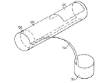
血管内プロテーゼ100は、カテーテル50に取り付けられている。
【0027】
カテーテル50は、膨張可能なバルーン55とガイドワイヤ60とを備えている。カテーテル50、膨張可能なバルーン55およびガイドワイヤ60は、従来のものである。当該技術では周知のように、膨張可能なバルーン55は、ガイドワイヤ60に沿って移動可能である。
【0028】
血管内プロテーゼ100は、本体105で構成されている。本体105は、近位端部110および遠位端部115を備えている。血管内プロテーゼ100は、さらに、第1の拡張可能部分130に付着される拡張可能なリーフ部分120(第2の拡張可能部分)を備えている。図示されるように、リーフ部分120は、カバーされた部分125を備えている。血管内プロテーゼ100は、さらに、スピン140によって第1の拡張可能部分130に接続される第3の拡張可能部分135を備えている。
【0029】
本体105は、ほぼ管状要素であり、ターゲット本体通路に通過されることが可能なように、さらに、ターゲット本体通路の適切な位置に固定されることが可能なように、十分に弾力性があるように構成されている。
【0030】
これを達成するための1つのアプローチは、ステントに類似する構造から血管内プロテーゼを較正することである。当該技術では周知のように、ステントは、一般に、本体通路(例えば、血管、呼吸器官、胃腸管など)の開通性を得て、維持するのに使用される拡張可能なプロテーゼである。ステントの2つの一般的な設計要求は、(i)ターゲット本体通路に無傷で通過されることが可能なように拡張されていない状態で十分に柔軟であることと、(ii)狭窄および/またはステント反跳の発生を回避するために、拡張された状態で十分に、また迅速に固定する必要があることとである。本血管内プロテーゼの最も好ましい実施形態は、設計要求(ii)が満たされないので、すなわち、本血管内プロテーゼの目的は、閉鎖された本体通路の開通性を維持しないので、ステント自体でなく、動脈瘤などを処置するための1つである。むしろ、本血管内プロテーゼのこの好ましい実施形態は、正確な位置にプロテーゼを固定するための1つ以上の拡張可能な要素を備えている。もちろん、本血管内プロテーゼの二重の拡張機能性の新規なアプローチは、適切な適用におけるステントに適用可能である。
【0031】
従って、このアプローチにおいて、本体105は、複数の交差部材によって形成され多孔を有する多孔性管である(明確にするために、多孔性の本体105は、図1乃至4には図示されていない)。交差部材の精密なパターンは、特に制約されず、拡張されていない状態で多孔性管の十分な柔軟性を達成するように選択されるべきであり、また管への迅速な外力の印加時、少なくともある程度の拡張を達成するポテンシャルを有している。一般に、複数の交差部材は、規則的に繰り返しパターンを形成するように配置されている。例えば、下記の同時係属特許出願に記述される様々な繰り返しパターンを参照してください。
【0032】
カナダ特許出願番号第2、134、997号(1994年11月3日出願);カナダ特許出願番号第2、171、047号(1996年3月5日出願);カナダ特許出願番号第2、175、722号(1996年5月3日出願);カナダ特許出願番号第2、185、740号(1996年9月17日出願);カナダ特許出願番号第2、192、520号(1996年12月10日出願);国際特許出願番号PCT/CA97/00151(1997年3月5日出願);国際特許出願番号PCT/CA97/00152(1997年3月5日出願);国際特許出願番号PCT/CA97/00294(1997年5月2日出願)(以後、ひとまとめにして「Divysio特許出願」と呼ばれる)および様々な参照がここに引用されている。Divysio特許出願に開示されている繰り返しパターンは、ステント設計の使用に適しており、それらは、結果として生ずる管状構造が、ステントとして有利に有用でないにもかかわらず、本血管内プロテーゼの好ましい実施形態において有用である管状構造のフレキシビリティを増大するために変更される(例えば、Divysio特許出願に教示される多角形の設計を部分的に変えることによって)。
【0033】
本体105は、あらゆる適切な材料から構成されることが可能である。1つの好ましい実施形態において、本体105は、メタル、合金、ポリマーなどの可塑性のあるように変形可能な材料から構成されている。適切な材料の制約されるものでない例示および合金は、ステンレス鋼、チタニウムなどからなる群から選択されることが可能である。本体105を拡張するのに使用される迅速な外力は、下記により詳細に記述されるように、カテーテルに取り付けられたバルーンの膨張によって印加される。別の好ましい実施形態において、本体105は、少なくとも約30℃の温度で、好ましくは、約30℃から約40度の範囲で、自己拡張可能な「形状記憶」メタル合金(例えば、ニチノール)から構成される。固有の径方向の外力が、プログラムされた自己拡張温度での環境に曝されるとき、本体105の拡張を生じることが認められている。さらに、別の好ましい実施形態において、本体105は、生物分解性材料から構成されることが可能である。当該技術では周知のように、生物分解性材料は、延長された接触で、本体流体で生物分解し、動脈瘤閉塞が動脈瘤開口を閉鎖後数分内に生じるので、本血管内プロテーゼに有用である。
【0034】
本体105が製造される方法は、特に制約されない。好ましくは、本体105は、管状スターティング材料に適用されるレーザカット技術によって製造される。このように、このスターティング材料は、上述の所望の繰り返しパターンを残すようにカットされる断面を有し、上述のようなメタル、合金あるいはポリマー製の薄い壁をめぐらした管である。図5乃至8は、血管内プロテーゼ100の種々の要素が、管状のスターティング材料からカットされる方法を図示している(もう一度、明確にするために、特定の多孔性の本体105は、図5乃至8に図示されていない)。
【0035】
別の実施形態において、1つ以上の予め形成されたワイヤから所望の多孔性の繰り返しパターンを有する本体105を構成することが可能である。別の異なる実施形態において、任意に溶接技術を組み合わせて、フラットなレーザカット技術を使用して所望の多孔性の繰り返しパターンを構成することが可能である。
【0036】
血管内プロテーゼ100は、更に、その上にコーティング材料を備えている。コーティング材料は、プロテーゼの表面に配置される。更に、コーティングは、プロテーゼの内部および/または外部表面に配置される。コーティング材料は、1つ以上の生物学的に不活性材料(例えば、プロテーゼのthrombogenicityを減少するため)、植え込み後本体通路の壁に浸出する医療組成物(例えば、凝固性作用を供給するため、本体通路に薬剤を分配するため)などであることが可能である。
【0037】
血管内プロテーゼ100は、本体の管の壁および/または管を通り流動する液体、通常血液と、不都合な相互作用を最小化するために、生物学適合性のコーティングを供給することが好ましい。コーティングは、一般に、溶媒の作用されたポリマーの溶解あるいは分散をプロテーゼに適用することによって、また溶媒を除去することによって供給される重合体材料であることが好ましい。重合体で内コーティング材料は、別の方法で使用される。ポリマーなどの適切なコーティング材料は、ポリテトラフルオロエチレン、シリコーンゴム、生物学的適合性であると周知であるポリウレタンなどである。好ましくは、ポリマーは、双生イオンペンダント群、一般に、リン安エステル群、あるいはホスホリルコリン群、あるいはそれらの類似物を有している。適切なポリマーの例示は、国際公告番号WO93/16479に記述されている。これらの明細書に記述されているポリマーは、血液融和性であり、一般に、生物学的適合性であり、さらに、平滑潤滑性である。プロテーゼの表面が、親の管(parent vessel)の血栓症に至る例えば、血液との好ましくない相互作用を最小とするために、完全にコーティングされていることを確実にすることが重要である。
【0038】
この良好なコーティングは、コーティング溶解速度、コーティング技術および/または溶媒除去ステップなどのコーティング状態の適当な選択によって達成されることが可能である。
【0039】
更に図1を参照すると、血管内プロテーゼ100を植え込むことを所望すると、カテーテル50のバルーン55に取り付けられる。ガイドワイヤ60は、矢印Aの方向に基底動脈10に取り付けられる。
【0040】
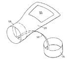
図2を参照すると、カテーテル50のバルーン55に取り付けられる血管内プロテーゼ100は、従来のガイドワイヤおよび蛍光透視法技術を使用して動脈瘤30の位置に進まれる。図示される実施形態において、本体105の遠位端部115は、第2動脈20に入る。実際問題として、基底動脈の分岐点の第2動脈は、非対称であり、本体105の遠位端部115は、2つの第2動脈の大きい方に進まれることが好ましい。更に、図示される実施形態において、本体105は、第2動脈20の方のナビゲーションに固定されるとき、リーフ部分120は、上がるか、あるいは開口135を形成するために、本体105の管状面に対して整列の外側に移動する。
【0041】
図3及び4では、血管内プロテーゼ100は修正位置に入ると、バルーン55は拡張し、それによって第1の拡張可能部分130及び第3の拡張可能部分135に対し放射状に外側に向かって力を及ぼす。その結果、まず本体105を拡張し、その位置は基底動脈10及び2次動脈20の両方の壁を圧迫する。その結果、以下詳細に既述される如くリーフ部分120は拡張する。図3に図示された実施形態では、バルーン55がそれによりリーフ部分120が拡張する程度に拡張し、動脈瘤30の開き35を阻止する様に2次動脈20、25の壁に押しつけられる。
【0042】
図4では、バルーン55は収縮し、ガイドワイヤー60と共に血管内プロテーゼ100より引き抜かれる。例示された実施形態では、血管内プロテーゼ100は、第1の拡張可能部分130及び第3の拡張可能部分135が基底動脈10と2次動脈20の壁に押しつけられることで、その位置に固定される。更に、例示した実施形態では、リーフ部分120はそれに加わる血流による力及び本体105の撓みによる固有の力の組み合わせによって固定され、遠位端部115を2次動脈20内に誘導する。リーフ部分120が開き35を阻止すると、動脈瘤30がなくなる。
【0043】
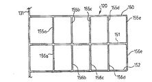
図9−11では、本発明の血管内プロテーゼ100の特に好ましい実施形態が例示されている。例示の如く、血管内プロテーゼは可塑的に変形可能な材料(例えばステンレス鋼)より構成された薄肉チューブより、例示デザインをエッチングすることで作製される。示される様に、単一突起140のみが第1の拡張可能部分130及び第3の拡張可能部分135と相互接続される。
【0044】
図10−11には、リーフ部分120(第2の拡張可能部分)の「シェブロン」機能が例示されている。即ち、リーフ部分120は相互に実質平行である縦ストラット150,151,152を含む。縦ストラット150,151、152はストラットの組155a/156a、155b/156b、155c/156c、155d/156d及び155e/156eにより相互に接続している。明らかなように、ストラット155/156は交点(縦ストラット151にて)で合致し鋭角を規定する。
【0045】
縦ストラット150,151,152は第1の拡張可能部分130に含まれる環状ストラット131に接続する。例示の如く、二次元的にはストラット131は正弦型(又は波形様あるいは波動型、もしくは蛇行型)のデザインである。当業者に明らかな様に、ストラット131の正弦型設計は二次元的には凸頂部132及び凹頂部133を規定する。本明細書を通し用いられる如く、「凹頂部」という用語は第1の拡張可能部分130に向かう頂部を意味し、「凸頂部」という用語は第1の拡張可能部分130より遠ざかる頂部を意味する。例示実施形態では、ストラット131は凸頂部132及び凹頂部133が変化した複数のものを含んでいる。例示の如く、縦ストラット150及び152は凸頂部132に接続し、縦ストラット151は凹頂部133に接続している。
【0046】
第1の拡張可能部分130が上記の如く拡張すると、環状ストラット131の放射状拡張が起こる。即ち、第1の拡張可能部分130が拡張すると、環状ストラット131は矢印Bの方向に伸長し、その結果ストラット131は実質的に直線状になる。ストラット131の直線化により、縦ストラット150及び152の矢印C方向への運動(即ち、ストラット131方向への引き込み)及び縦ストラット151の矢印D方向への運動(即ち、ストラット131から押し出される)が起こる。同時に、ストラット155/156間に形成される鋭角が広がり、最適例(図11)に於いてはストラット155/156は共線となる。
【0047】
当業者には明らかなように、拡張したリーフ部分120(図11)の表面積は、非拡張時のリーフ部分20(図10)のそれに比べ大きい。従って、所与の管寸法を持つ本発明の血管内プロテーゼは、展開時に単純に開く(即ち、それ自体直線状になるが展開しない)同一管寸法を有するリーフ部分の表面積に比べて広い表面積を拡張時に有するリーフ部分を保持している。
【0048】
明瞭にするために、図9−11を参照した上記既述はカバー部分125を含んでいない。実際には、リーフ部分120の大部分又は全ては;(i)リーフ部分120の拡張に耐え、そして(ii)展開後の動脈瘤30の開き35を阻止するのに適した材料でカバーされることが好ましい。この目的に使用される材料の特製は特に限定されない。好ましくは、材料はCardiothane51TM(Kontron Instruments,Inc.,Everett、Massachusetts)、血管内用具(例えば動脈内心臓補助用具のバルーン材料の様な)に有用であることが既知である医療用等級のポリウレタン/シリコーンポリマーを含むことが好ましい。即ち、「未処理」リーフ部分120はまず5.7%重量:容積(w:v)の有機溶媒(例えばテトラヒドロフラン:1,4−ジオキサン、2:1)に溶解されたCardiothane51TM液により被覆される。初期コートされたリーフ部分120は更に次に同一溶媒に溶解されたCardiothane51TMの11.7%w:v液で被覆される。ポリマーが乾燥すると、リーフ部分120のストラットは本質的にポリウレタン−シリコーンカバーに埋没する。次にカバーされたリーフ部分120はエチレンオキサイドにより滅菌される。本方法に関する情報に関しては、Okoshiらによる”In Vivo Evaluation of Porous Versus Skinned Polyurethane−Polydimethylsiloxane Small Diameter Vascular Grafts”、ASAIO Transactions 1991;37:M480−M481を参照せよ。
【0049】
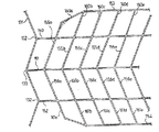
図12及び13では、図10及び11に例示されたリーフ部分120の変形が例示されている(注意;図10−13内の参照番号は互いに同等要素を示している)。即ち、例示の如く、図12及び13に見られる変形は、縦ストラット153、154の追加の対を含んでいる。縦ストラット150及び153は複数のストラット160a、160b、160c、160d、160e等により相互に接続されている。同様に、縦ストラット152と154は複数のストラット161a、161b、161c、161d、161e等により相互に接続されている。示すように、縦ストラット153、154は環状ストラット131には直接接続していない。これが拡張状態におけるリーフ部分120の表面積を最大にしながら、第1の拡張可能部分130に対するリーフ部分120の独立した運動を容易にしている(図13)。更に、ストラット160a,161aは、リーフ部分120が非拡張状態にある場合(図12)には屈曲している(又は角度を持っている)ことが分かる。これが、図13に示す様に、リーフ部分120の拡張を容易にしている。
【0050】
図14には、図10と11に示すリーフ部分120の変形形態を示す(図10、11および14の同一参照符号は同一要素を指すものであり、異なる符号は異なる要素を指す)。図4に示すリーフ部分の1つの変形形態は、縦ストラット150aと152aを提供し、それらは縦ストラット150と152および151よりそれぞれ薄い。この変形形態により、縦ストラット151に対して矢印D方向に加えられた力により、ストラット150aと152a内の矢印C方向に発生する応力にほぼ等しくなっている。さらに縦ストラット150、151、152、およびストラット155(a、b、c、d)と156(a、b、c、d)間の一連の接続170は、より薄く、より大きい内部半径に変更されている。この変形形態により、接続170の曲げとリーフ部分の開きつまり展開が容易になっている。
【0051】
図15には、図10−14に示すリーフ部分の変形形態を示す。
【0052】
図15は、本発明の血管内プロテーゼ200の好ましい実施形態の2つの寸法表示を示す。プロテーゼ200は第1の拡張可能部分205と第2の拡張可能部分210を備える。第1の拡張可能部分205と第2の拡張可能部分210はストラット214、216および突起215、217により相互に接続されている。
【0053】
図示した実施形態では、第1の拡張可能部分205と第2の拡張可能部分210は各々、上記のDivysioの特許出願に開示された、一連の相互接続された部材で規定された多孔性表面を有する。
【0054】
血管内プロテーゼ200はリーフ部分220を備える。リーフ部分220は、1対のジョー部材225、230を備える。ジョー部材225、230は各々、内部に配列した微小カットを有する表面を備える。この微小カットは、従来のレーザカット技術等によって、ジョー部材225、230内に配置される。
【0055】
ジョー部材225、230は、接続部材235によって、その端部で相互に接続されている。さらに、ジョー部材225は、ストラット218によって突起215に接続されている。同様に、ジョー部材230はストラット219によって突起217に接続されている。図のように、ストラット218は、ジョー部材225とストラット216を相互接続する。同様に、ストラット219は、ジョー部材225とストラット216を相互接続する。
【0056】
第2の拡張可能部分210は、上記のように拡張し、ジョー部材225、230と第2の拡張可能部分210間の連結241を相互接続する接続ストラット240が、接続ストラット240を矢印E方向に動かす(すなわち、連結241を接続部材235方向に押す)。同時に、ストラット218、219は、ジョー部材225、230を、矢印F方向に引っ張り、その結果ジョー部材225、230は連結241周りを回転して、接続部材235を開く。
【0057】
カバー材料(明白には示していない)がジョー部材225、230に取付けられており、このカバー材料はジョー部材225、230の拡張時に開いてリ−フ部分220の表面面積を最適化する。
【0058】
生物医学的な特性を持つ限り(すなわち管腔に安全に使用し、内部に残留しない)、コーティング材料の特性は特に限定されず、上記の実施形態に関連するコーティング材料の種類であってもよい。コーティング材料は伸縮性であっても(上記のように)、そうでなくてもよい。コーティング材料はDacronTM、GoretexTMなどであってもよい。コーティング材料はジョー部材225、230に縫い合わせることもできる。代替方法として、コーティング材料はジョー部材225、230に接着することもできる。コーティング材料をジョー部材225、230確実に固定する特殊方法は、特に限定しない。
【0059】
コーティング材料をジョー部材225、230に固定した後に、リーフ部分220を拡張できる。代替方法は、リーフ部分220の一部または全体を予め拡張して、コーティング材料を固定し、その後リーフ部分220を予め配置した適当な状態に折り曲げまたは折り返しことも可能である。
【0060】
図15に示す血管内プロテーゼ200の好ましい実施形態は、特に好ましいものである、なぜならリーフ部分220の拡張がコーティング材料を引き伸ばす力を必要としないからである(これは、図9−14の実施形態と対称的である)。
【0061】
さらに血管内プロテーゼ200の内の突起215、217は、拡張血管内プロテーゼ200に対しさらに「好ましい柔軟性」を与える利点を提供する。この好ましい柔軟性は、リーフ部分220を、固定されたプロテーゼによって描かれる円弧の外側に維持し、リーフ部分220を動脈瘤のネックに対向する位置に維持する。
【0062】
図15に示す実施形態では、リーフ部分220は、接続ストラット240の「押し」と、上記のストラット218、219の「引張り」の同時作用で拡張される。当業者には、場合によっては、図示した実施形態を変更して、上記の「押し」または「引張り」のどちらか、またはその他の方法を用いてリーフ部分220の拡張を達成できることは、容易に認識される。
【0063】
ここまたは上記に示す本発明の血管内プロテーゼでは、場合によっては、リーフ部分のエッジにタブまたは同様の装置を使用して、カテーテルまたはプロテーゼに分配するのに使用する他の分配システムからのリーフの持ち上がりを防ぐことができる、またむしろ好ましい場合もある。このタブはバルーンに巻く周囲ラップを増加でき、装置の分配の間、リーフ部分をブルーン長さに沿って低いプロファイルに維持できる。これらのタブは容易に設計して、バルーンからリーフ部分を「分離」または開放し(すなわち器官の配置の間)、上記に利点を達成できる。
【0064】
本発明の範囲と精神から逸脱しない上記の特定の実施形態の他の代替方法および変更は、本明細書を有する当業者には明らかである。たとえば、各種の示した実施形態では、リーフ部分は、分配の間、器官の近接端に方向の点で示されるが、これは場合によっては重要でなく、逆方向が好ましいこともある。さらに、各種の示した実施形態では、脳動脈瘤を治療する血管内プロテーゼであるが、本発明の血管内プロテーゼを使用して、他のタイプの脳動脈瘤の治療および他の血管内用途に使用できることは、当業者には明らかである。さらに、各種の示した実施形態では、1対の拡張可能環状輪を示しているが、単一拡張可能環状輪または、3またはそれ以上の拡張可能環状輪を使用してこの器官を構成できる。さらに、各種の示した実施形態では、本体の拡張可能部分に多孔性構造を持つ1対のリングを備えるが、多孔性構造でない構造を有するリングを使用して、たとえばリングを折りたたみ、取外しできる固定機構を使用して(取外しは、展開状態にリングを開くことができる)、この状態に維持することもできる(本実施形態では、リング寸法はその最終植込み直径で、折たたまれ−たとえば国際公開番号WO95/26695参照)。本発明の精神と範囲を逸脱しないその他の変更は、本明細書を所有する当業者には明らかである。
【0065】
ここに引用するすべての発行物、特許および特許明細書は、同一範囲までその全体を本明細書に引用している。ただし、各個々の発行物、特許および特許明細書が、特におよび単独にその全体を引用することを指定しない場合である。
【図面の簡単な説明】
【図1】 図1は、血管内プロテーゼが移植される基底動脈の終端分岐の断面図である。
【図2】 図2は、血管内プロテーゼが移植される基底動脈の終端分岐の断面図である。
【図3】 図3は、血管内プロテーゼが移植される基底動脈の終端分岐の断面図である。
【図4】 図4は、図3のIV−IVから見た拡大断面図である。
【図5】 図5は、模式的に示した血管内プロテーゼの好ましい実施の形態の斜視図である。
【図6】 図6は、模式的に示した血管内プロテーゼの好ましい実施の形態の斜視図である。
【図7】 図7は、模式的に示した血管内プロテーゼの好ましい実施の形態の斜視図である。
【図8】 図8は、模式的に示した血管内プロテーゼの好ましい実施の形態の斜視図である。
【図9】 図9は、血管内プロテーゼの特に好適な実施の形態の斜視図である。
【図10】 図10は、血管内プロテーゼに表れた「山形」効果の一実施の形態を二次元的に示した図である。
【図11】 図11は、血管内プロテーゼに表れた「山形」効果の一実施の形態を二次元的に示した図である。
【図12】 図12は、血管内プロテーゼに表れた「山形」効果の他の実施の形態を二次元的に示した図である。
【図13】 図13は、血管内プロテーゼに表れた「山形」効果の他の実施の形態を二次元的に示した図である。
【図14】 図14は、血管内プロテーゼにおいて有用な拡張薄片部の第1の実施の形態を示す図である。
【図15】 図15は、血管内プロテーゼにおいて有用な拡張薄片部の第2の実施の形態を示す図である。[0001]
BACKGROUND OF THE INVENTION
In one of its aspects, the present invention provides an intravascular vessel. Prosthesis About. In another aspect, the present invention relates to a method for treating an aneurysm in a patient.
[0002]
[Prior art]
As is known in the art, an aneurysm is an abnormal outward bulge in the wall of the artery. The bulge may be in the form of a smooth bulge outward in all directions from the artery. This is known as a “fusiform aneurysm”. The bulge may also be in the form of a bag that originates from an arterial bifurcation or from one side of the artery. This is known as a “saccular aneurysm”.
[0003]
Aneurysms can occur in any artery in the body, but it is usually in the brain that leads to a stroke. Most saccular aneurysms arising in the brain have necks that extend from the cerebral blood vessels and extend into the sac protruding from the blood vessels.
[0004]
The problems caused by such aneurysms arise in several different ways. For example, when an aneurysm ruptures, blood enters the brain or subarachnoid space (a space close to the brain). The latter is known as aneurysm subarachnoid hemorrhage. This can cause one or more of the following symptoms: nausea, vomiting, double vision, cervical stiffness, and unconsciousness. Subarachnoid hemorrhage is an emergency medical condition that requires immediate treatment. In fact, 10-15% of patients in this condition die before arriving at the hospital for treatment. More than 50% of patients with this condition will die within the first 30 days of bleeding. About half of the helped patients will suffer from permanent seizures. Some seizures result from cerebral vasospasm induced by subarachnoid hemorrhage 1-2 weeks after the bleeding itself. Aneurysms can also cause problems that are less common but not related to bleeding. For example, an aneurysm may form a blood clot that can be transported away from the aneurysm where it can inhibit the branching of the artery and cause a seizure. In addition, an aneurysm can compress nerves (which can cause abnormal sensation or paralysis of one eye or face) or can press on the adjacent brain (which can cause a stroke).
[0005]
Given the fatal consequences of aneurysms, especially cerebral aneurysms, the technology has dealt with treating aneurysms using various approaches.
[0006]
In general, aneurysms may be treated from the outside of the blood vessel using surgical techniques or from the inside using endovascular techniques (the latter is a broader intervention (nonsurgical) Belongs to technology).
[0007]
Surgical techniques typically involve craniotomy where the surgeon needs to drill a hole in the patient's skull to insert an instrument that directly operates on the brain. In one approach, the brain is contracted to expose the blood vessel in which the aneurysm has occurred, and the surgeon attaches a clip to the neck of the aneurysm, thereby preventing arterial blood from entering the aneurysm. If the aneurysm is clotted, the clip also prevents the clot from entering the artery and prevents the occurrence of seizures. By attaching the clip correctly, the aneurysm is blocked within minutes. Unfortunately, surgical techniques to treat such conditions are considered high-risk major surgeries for the patient, and the patient is required to be physically strong just to get through the procedure successfully.
[0008]
As mentioned above, intravascular techniques are non-surgical techniques and are generally performed by angiography using a catheter delivery system. Specifically, known intravascular techniques involve the use of a catheter delivery system that fills the aneurysm with a material that prevents arterial blood from entering the aneurysm. This technique is widely known as an embolization method. An example of such an approach is the Guglielmi separable coil with intra-aneurysm occlusion of the aneurysm via a platinum coil attached to a stainless steel delivery line and a system using electrolyte dissociation. Once the platinum coil is placed in the aneurysm, it will dislodge from the stainless steel delivery wire due to electrolyte dissolution. Specifically, the patient's blood and salt-containing infusion work as a conductive solution. The anode is a stainless steel delivery wire, and the cathode is a grounding needle attached to the patient's groin. Once current is sent to the stainless steel delivery line, electrolyte dissolution occurs in the non-insulated part of the stainless steel separation zone in the immediate vicinity of the platinum coil (the platinum coil is of course not affected by electrolysis). Other approaches involve the use of materials such as cellulose acetate polymer to fill the aneurysm sac. Although these endovascular approaches are technological advances, they also have drawbacks. Specifically, the risks of these endovascular approaches include rupture of the aneurysm during the procedure and seizures due to emboli formation or coagulation from the aneurysm during the procedure. Furthermore, there are concerns regarding the long-term consequences of intravascular aneurysm blockage using these techniques. Specifically, there is evidence of aneurysm reproduction in aneurysm translocation of the filling material and following angiography.
[0009]
Regarding cerebral aneurysms, cases that are particularly difficult to treat by the aforementioned surgical clipping method or endovascular embolization method occur in the terminal basilar artery. This type of aneurysm is a thin sac and is often located at the terminal bifurcation of the basilar artery. The treatment of this type of aneurysm has the absolute requirement that all brainstem transvascular vessels must be preserved during clipping during surgery, which is very difficult to treat for at least part of the reason It is.
[0010]
Depending on the size, shape and location of each patient's aneurysm, neither surgical clipping nor endovascular embolization may be possible. Moreover, the prognosis for such patients is generally poor.
[0011]
Although the prior art in the field of aneurysm treatment has progressed so far, endovascular embolization has attracted attention as an alternative to major surgery, and there is still room for development in this method. Yes. Furthermore, intravascular used to embolize aneurysms that are difficult or impossible to treat by other methods. Prosthesis Is required. Also, such intravascular Prosthesis However, it can be used in aneurysms currently undergoing endovascular treatment, and there is a need to alleviate and eliminate the disadvantages of current endovascular embolization methods.
[0012]
[Problems to be solved by the invention]
The object of the present invention is to provide a novel intravascular device that eliminates or alleviates at least one of the disadvantages of the prior art as described above. Prosthesis Is to provide.
[0013]
Another object of the present invention is to provide a novel endovascular blocking method for an aneurysm opening that eliminates or alleviates at least one of the disadvantages of the prior art as described above.
[0014]
[Means for Solving the Problems]
Therefore, the present invention is in one aspect thereof, Expandable Intravascular Prosthesis This brace is: a body having a base and an end, and is located between the base and the end and is first when a radial outward force is applied Expansion 2nd from the previous state Expansion To the back state Expansion The first that is possible Expandable part Because of this force, the first Expandable part Is pressed into the vessel lumen, the first Expandable part Connected to the second Expandable part And the second Expandable part Is the first Expandable part of Expansion With Is extensible Are provided.
[0015]
Furthermore, in another aspect, the present invention provides Prosthesis This relates to an intravascular blocking method for an aneurysm opening. Prosthesis Is located between the base and the end, and between the base and the end, and when a radially outward force is applied, the first Expansion 2nd from the previous state Expansion To the back state Expansion A first force that is pressed against the vessel lumen by this force. Expandable part And the first Expandable part Connected to the first Expandable part of Expansion With Expansion Second to Expandable part The method is: Prosthesis Placing the catheter in a catheter; Prosthesis Inserting the catheter and the catheter into the body passage using the body passage catheterization method; Prosthesis Moving the catheter and catheter to the target vessel lumen where the aneurysm opening is located, and applying a radial outward force to the first Expandable part The first of the tubular Expandable part Pressing the desired body passageway and a first Expandable part of Expansion By the second Expandable part The Expansion And a second step Expandable part Pressing against the aneurysm opening to block the aneurysm opening.
[0016]
This allows the inventor to Expandable part But Expansion When the first ( Expandable part Connected to the second) Expandable part The Expansion New blood vessels with the characteristic of Prosthesis I found For example, the first Expandable part Is formed of a plastically deformable material (stainless steel, etc.), the first Expandable part Is Expansion When it is plastically deformed. And like this Expansion By the second Expandable part But Expansion To do. As described below, intravascular with these characteristics Prosthesis Is particularly suitable for the treatment of aneurysms.
[0017]
As described further below, the first Expandable part The shape is preferably generally tubular. In fact, in this specification, the first Expandable part Refers to what is generally tubular. However, this is only for the purpose of illustration, and if you are knowledgeable in this field, Expandable part As non-tubular structure ( Expansion Then, it will be recognized that a claw-shaped one) can also be used.
[0018]
International publication WO 99/40873 published on August 19, 1999 [Marotta et al. (Marotta) shows a novel approach in blood vessels. It is useful for blocking aneurysmal hiatus . This is particularly effective in the case of a saccular aneurysm and relates to the removal of the aneurysm. This method is truly intravascular . Because the intravascular system disclosed in Marotta Prosthesis This is because there is no requirement to pack the aneurysm sac with some material (eg, for use with a Guglielmi-type separable coil). Rather, intravascular as disclosed in Marotta Prosthesis Now shield the aneurysm sac and eliminate the need for substance filling . Therefore, within the blood vessels disclosed in Marotta Prosthesis Eliminates many of the disadvantages of the prior art and has made significant progress. Intravascular disclosed in Marotta Prosthesis Contains leaf part . The leaf portion is pressed against the aneurysmal cleft and closes the aneurysm. Within the blood vessels disclosed in Marotta Prosthesis The leaf portion is then independently movably bonded to a body including at least one expandable portion. The expandable part is due to the force acting radially outward First From the unexpanded state Second Expand to the expanded state. In this way, the body can be used to achieve its main purpose. Prosthesis Is positioned in a target body lumen or blood vessel near the aneurysmal hiatus. The leaf portion seals the aneurysmal hiatus and removes the aneurysm. As disclosed in Marotta, the leaf portion functions and Prosthesis It can move independently of the main body.
[0019]
Within the blood vessels disclosed in Marotta Prosthesis Was an important advance in the prior art, but there is still room for improvement. In particular, intravascular as disclosed in Marotta Prosthesis In the preferred embodiment, once the device is in place and the leaf portion is correctly positioned, the surface of the leaf portion is limited to the surface of the tube from which the leaf portion has been cut. This is often not a problem, but the aneurysm may be quite large and the leaf portion may not sufficiently occlude the aneurysmal hiatus. On the other hand, if you try to cut a leaf part out of a larger diameter tube to get a larger size leaf part, the diameter of the fissure will widen, making it more difficult to insert into the correct position or use a conventional loading device To.
[0020]
The inventors of the present application have discovered a novel approach. according to it, Prosthesis The body is designed to have a conventional tube diameter and is provided with an expandable part that expands as the body expands . Intravascular of this application Prosthesis According to the main body has a proximal end and a distal end, between which at least two expandable parts are provided connected to each other . First The expandable part of the First From the unexpanded state Second Expand to the expanded state. Second The expandable part of First Connected to the expandable part of First Can be extended according to the extension of That is, First The means for expanding the expandable part of Second The expandable part of is not directly expanded.
[0021]
Intravascular of the present invention Prosthesis The main body is generally elastic with a long axis. In a preferred embodiment, Second Expandable portion Is at least with respect to the body First And the position of Second It is possible to move independently between the positions. That is, it does not expand. First In the position of ( First Expandable portion The tip and end of the body Second Expandable portion Align with. Second In the position of, while fixing the tip and end of the body, Second Expandable portion Do some independent movement. In this way Second Expandable portion Is “movable” with respect to the body. In one embodiment, preferably intravascular Prosthesis To turn against the rest of the Second Expandable portion This independent movement is performed by arranging. You should understand the following: Second Expandable portion When moving independently with respect to the body, Second Expandable portion The final alignment (that is, the alignment after the aneurysm opening is closed) is not particularly limited and depends on factors such as the size and position of the aneurysm and the physical structure of the particular patient. The key points of this preferred embodiment are Second Expandable portion Is movable independently of the main body.
[0022]
Intravascular of the present invention Prosthesis Is particularly useful for the treatment of aneurysms such as those described above, and is considered an important alternative to conventional surgical techniques. Further, in the blood vessel of the present invention Prosthesis May be used to treat aneurysms diagnosed as inoperable. Inside the blood vessel Prosthesis Is also believed to produce an important effect of the technique of using an electric current in a blood vessel like the Guglielmi type separable coil described above. Specifically, in blood vessels Prosthesis Is not associated with inserting a metal filler (eg, platinum coil) into the aneurysm, so the risk of rupturing the aneurysm is mitigated, and the metal filler is relocated within the aneurysm and the aneurysm is again The risk of appearing is reduced.
[0023]
DETAILED DESCRIPTION OF THE INVENTION
Embodiments of the present invention will be described with reference to the accompanying drawings. In the drawings, the same members are denoted by the same reference numerals.
[0024]
With reference to FIGS. Prosthesis The first embodiment of the invention describes specific criteria for the same implantation at the terminal bifurcation of the basal artery.
[0025]
Thus, the
[0026]
[0027]
The
[0028]
Intravascular Prosthesis Reference numeral 100 denotes a
[0029]
The
[0030]
One approach to achieve this is Stent From structures similar to Prosthesis Is to calibrate. As is well known in the art, Stent Are generally expandable used to obtain and maintain patency of body passageways (eg, blood vessels, respiratory organs, gastrointestinal tract, etc.) Prosthesis It is. Stent The two general design requirements are: (i) sufficiently flexible in an unexpanded state so that it can be passed intact into the target body passage; and (ii) stenosis and / or Stent In order to avoid the occurrence of recoil, it needs to be fixed sufficiently and quickly in the expanded state. In the main blood vessel Prosthesis The most preferred embodiment of design Since requirement (ii) is not fulfilled, ie within this vessel Prosthesis The purpose of is not to maintain the patency of the closed body passage, Stent It is one for treating an aneurysm or the like instead of itself. Rather, inside this blood vessel Prosthesis This preferred embodiment of the Prosthesis One or more expandable elements for securing the. Of course, in this blood vessel Prosthesis The new dual extended functionality approach is Stent It is applicable to.
[0031]
Thus, in this approach, the
[0032]
Canadian Patent Application No. 2,134,997 (filed on November 3, 1994); Canadian Patent Application Number 2,171,047 (filed on March 5, 1996) ; Canadian Patent Application No. 2,175,722 (filed on May 3, 1996) ; Canadian Patent Application No. 2,185,740 (filed September 17, 1996) ; Canadian Patent Application No. 2,192,520 (filed December 10, 1996) ; International patent application number PCT / CA97 / 00151 (filed on March 5, 1997) ; International Patent Application Number PCT / CA97 / 00152 (filed on March 5, 1997) ; International Patent Application Number PCT / CA97 / 00294 (filed on May 2, 1997) ( After that Collectively referred to as “Diviosio patent application”) and various references are cited herein. The repetitive pattern disclosed in the Divisio patent application is: Stent Suitable for use in design, as the resulting tubular structure is Stent Despite not being beneficially useful as this intravascular Prosthesis Are modified to increase the flexibility of the tubular structures that are useful in the preferred embodiments (eg, by partially changing the polygonal design taught in the Divysio patent application).
[0033]
The
[0034]
The method for manufacturing the
[0035]
In another embodiment, a desired from one or more preformed wires Porous It is possible to constitute the
[0036]
[0037]
[0038]
This good coating can be achieved by appropriate selection of coating conditions such as coating dissolution rate, coating technique and / or solvent removal step.
[0039]
Still referring to FIG. Prosthesis If it is desired to implant 100, the
[0040]
Referring to FIG. 2, the intravascular vessel attached to the
[0041]
In FIGS. 3 and 4, intravascular Prosthesis When 100 enters the correction position, the
[0042]
In FIG. 4, the
[0043]
9-11, the intravascular vessel of the
[0044]
10-11 shows the leaf portion 120 ( Second Expansion Possible The “chevron” function of (part) is illustrated. That is, the
[0045]
The
[0046]
First Expansion Possible part When 130 is expanded as described above, radial expansion of the
[0047]
As will be apparent to those skilled in the art, the surface area of the expanded leaf portion 120 (FIG. 11) is equal to the unexpanded leaf portion 20 (FIG. 10). of Bigger than that. Thus, the endovascular vessel of the present invention having a given tube size Prosthesis Is , It retains leaf portions that have a larger surface area when expanded compared to the surface area of leaf portions that have the same tube dimensions that simply open during deployment (i.e., themselves become linear but do not expand).
[0048]
For clarity, the above description with reference to FIGS. 9-11 does not include the
[0049]
12 and 13 illustrate a variation of the
[0050]
FIG. 14 shows a variation of the
[0051]
FIG. 15 shows a modification of the leaf portion shown in FIG. 10-14.
[0052]
FIG. 15 shows the intravascular structure of the present invention. Prosthesis Two dimensional representations of 200 preferred embodiments are shown.
[0053]
In the illustrated embodiment, First Expansion Possible With
[0054]
[0055]
The
[0056]
Second Expansion
[0057]
A cover material (not explicitly shown) is attached to the
[0058]
As long as it has biomedical properties (i.e., it can be safely used in the lumen and does not remain inside), the properties of the coating material are not particularly limited and may be the type of coating material associated with the above embodiment. . The coating material may or may not be stretchable (as described above). Coating material is Dacron TM , Goretex TM It may be. The coating material can also be sewn to the jaw members 225,230. Alternatively, the coating material can be adhered to the jaw members 225,230. The special method for securely fixing the coating material to the
[0059]
Coating material applied to
[0060]
Intravascular shown in FIG. Prosthesis The 200 preferred embodiments are particularly preferred because the expansion of the
[0061]
Furthermore, in the blood
[0062]
FIG. Shown in In an embodiment, the
[0063]
The blood vessel of the present invention shown here or above Prosthesis In some cases, using a tab or similar device at the edge of the leaf portion, Prosthesis The leaf lift from other dispensing systems used to dispense into can be prevented, and in some cases preferred. This tab can increase the circumferential wrap around the balloon and keep the leaf portion in a low profile along the length of the brune during device dispensing. These tabs can be easily designed to “separate” or open the leaf portion from the balloon (ie, during organ placement) to achieve the advantages described above.
[0064]
Other alternatives and modifications of the specific embodiments described above will be apparent to those skilled in the art having the specification without departing from the scope and spirit of the invention. For example, in various illustrated embodiments, the leaf portion is shown as a directional point at the proximal end of the organ during dispensing, but this is In Thus, it is not important and the reverse direction may be preferred. Further, in the various illustrated embodiments, an intravascular treatment for treating a cerebral aneurysm Prosthesis However, in the blood vessel of the present invention Prosthesis It will be apparent to those skilled in the art that can be used for the treatment of other types of cerebral aneurysms and other intravascular applications. Further, in the various illustrated embodiments, a pair of extensions Possible Annular ring is shown but single expansion Possible Annular ring or 3 or more expansions Possible An annular ring can be used to construct this organ. In addition, in the various illustrated embodiments, an extension of the body Possible A pair of rings with a porous structure in the part, but using a ring with a structure that is not a porous structure, for example using a locking mechanism that can fold and remove the ring Can be opened) and can be maintained in this state (in this embodiment, the ring dimension is folded at its final implant diameter—see, eg, International Publication No. WO 95/26695). Other modifications that do not depart from the spirit and scope of the invention will be apparent to those skilled in the art having the specification.
[0065]
All publications, patents and patent specifications cited herein are hereby incorporated by reference in their entirety to the same extent. However, each individual publication, patent and patent specification is not specifically and individually specified to cite it in its entirety.
[Brief description of the drawings]
FIG. 1 is an intravascular view Prosthesis FIG. 3 is a cross-sectional view of a terminal branch of a basal artery to be implanted.
FIG. 2 shows an intravascular Prosthesis FIG. 6 is a cross-sectional view of a terminal branch of a basal artery to be implanted.
FIG. 3 is an intravascular view Prosthesis FIG. 3 is a cross-sectional view of a terminal branch of a basal artery to be implanted.
4 is an enlarged cross-sectional view as seen from IV-IV in FIG. 3. FIG.
FIG. 5 is a schematic intravascular view Prosthesis It is a perspective view of a preferable embodiment.
FIG. 6 is a schematic intravascular view Prosthesis It is a perspective view of a preferable embodiment.
FIG. 7 is a schematic intravascular view Prosthesis It is a perspective view of a preferable embodiment.
FIG. 8 is a schematic intravascular view Prosthesis It is a perspective view of a preferable embodiment.
FIG. 9 shows an intravascular Prosthesis FIG. 2 is a perspective view of a particularly preferred embodiment of the present invention.
FIG. 10 is an intravascular view Prosthesis It is the figure which showed one Embodiment of the "Yamagata" effect which appeared in 2D.
FIG. 11 is an intravascular view Prosthesis It is the figure which showed one Embodiment of the "Yamagata" effect which appeared in 2D.
FIG. 12 is an intravascular view Prosthesis FIG. 10 is a diagram two-dimensionally showing another embodiment of the “Yamagata” effect appearing in FIG.
FIG. 13 is an intravascular view Prosthesis FIG. 10 is a diagram two-dimensionally showing another embodiment of the “Yamagata” effect appearing in FIG.
FIG. 14 is an intravascular view Prosthesis Of expanded flakes useful in First It is a figure which shows this embodiment.
FIG. 15 is an intravascular view Prosthesis Of expanded flakes useful in Second It is a figure which shows this embodiment.
Claims (14)
前記本体の基端部と先端部との間に配設され、開いていない第1の状態から管腔を径方向外方に付勢するように開いた第2の状態に拡張可能な管状の第1の拡張可能部分(130)と、
前記第1の拡張可能部分(130)に装着されたリーフ状の第2の拡張可能部分(120)と
を具備し、
前記第2の拡張可能部分(120)は、(i)前記第1の拡張可能部分(130)に対して独立して動くことが可能であり、(ii)第1の拡張可能部分(130)の拡張のときに拡張可能であることを特徴とする拡張可能な血管内プロテーゼ(100)。A body (105) having a proximal end (110) and a distal end (115) ;
A tubular tube disposed between a proximal end and a distal end of the main body and expandable from a first state that is not open to a second state that is open to urge the lumen radially outward; A first expandable portion (130) ;
A leaf-shaped second expandable portion (120) attached to the first expandable portion (130 );
Comprising
The second expandable portion (120) is capable of (i) moving independently of the first expandable portion (130), and (ii) the first expandable portion (130). An expandable endovascular prosthesis (100) characterized in that it is expandable when expanded .
Applications Claiming Priority (3)
| Application Number | Priority Date | Filing Date | Title |
|---|---|---|---|
| US11986199P | 1999-02-12 | 1999-02-12 | |
| US60/119,861 | 1999-02-12 | ||
| PCT/CA2000/000125 WO2000047134A1 (en) | 1999-02-12 | 2000-02-11 | Endovascular prosthesis |
Publications (3)
| Publication Number | Publication Date |
|---|---|
| JP2002536112A JP2002536112A (en) | 2002-10-29 |
| JP2002536112A5 JP2002536112A5 (en) | 2008-07-03 |
| JP4184609B2 true JP4184609B2 (en) | 2008-11-19 |
Family
ID=22386823
Family Applications (1)
| Application Number | Title | Priority Date | Filing Date |
|---|---|---|---|
| JP2000598088A Expired - Fee Related JP4184609B2 (en) | 1999-02-12 | 2000-02-11 | Endovascular prosthesis |
Country Status (8)
| Country | Link |
|---|---|
| EP (1) | EP1071378B1 (en) |
| JP (1) | JP4184609B2 (en) |
| CN (1) | CN1309353C (en) |
| AT (1) | ATE344643T1 (en) |
| AU (1) | AU2529600A (en) |
| CA (1) | CA2328232C (en) |
| DE (1) | DE60031743T2 (en) |
| WO (1) | WO2000047134A1 (en) |
Families Citing this family (24)
| Publication number | Priority date | Publication date | Assignee | Title |
|---|---|---|---|---|
| US6969401B1 (en) | 2000-08-18 | 2005-11-29 | Marotta Thomas R | Endovascular prosthesis |
| WO2002051336A1 (en) | 2000-12-15 | 2002-07-04 | Penn, Ian, M. | Endovascular prosthesis delivery system |
| AU2002215751A1 (en) | 2000-12-15 | 2002-06-24 | Marotta, Thomas A. | Endovascular prosthesis delivery system |
| DE10243136A1 (en) | 2002-09-17 | 2004-05-19 | Campus Medizin & Technik Gmbh | Stent for implantation in or around a hollow organ |
| EP1734897A4 (en) | 2004-03-31 | 2010-12-22 | Merlin Md Pte Ltd | A method for treating aneurysms |
| US8500751B2 (en) | 2004-03-31 | 2013-08-06 | Merlin Md Pte Ltd | Medical device |
| US20060030929A1 (en) * | 2004-08-09 | 2006-02-09 | Scimed Life Systems, Inc. | Flap-cover aneurysm stent |
| US9427340B2 (en) | 2004-12-14 | 2016-08-30 | Boston Scientific Scimed, Inc. | Stent with protruding branch portion for bifurcated vessels |
| US7833264B2 (en) * | 2006-03-06 | 2010-11-16 | Boston Scientific Scimed, Inc. | Bifurcated stent |
| CN101541263B (en) * | 2006-05-22 | 2013-04-24 | 塔伦·约翰·埃德温 | Tissue synthetic-biomaterial hybrid medical devices |
| US8216267B2 (en) | 2006-09-12 | 2012-07-10 | Boston Scientific Scimed, Inc. | Multilayer balloon for bifurcated stent delivery and methods of making and using the same |
| US8128686B2 (en) | 2008-04-18 | 2012-03-06 | Cook Medical Technologies Llc | Branched vessel prosthesis |
| US8932340B2 (en) | 2008-05-29 | 2015-01-13 | Boston Scientific Scimed, Inc. | Bifurcated stent and delivery system |
| JP6320914B2 (en) | 2011-04-29 | 2018-05-09 | エバスク・ニューロバスキュラー・リミテッド・パートナーシップEvasc Neurovascular Limited Partnership | Endovascular prostheses and delivery devices |
| WO2012154782A1 (en) | 2011-05-11 | 2012-11-15 | Tyco Healthcare Group Lp | Vascular remodeling device |
| US8771341B2 (en) * | 2011-11-04 | 2014-07-08 | Reverse Medical Corporation | Protuberant aneurysm bridging device and method of use |
| US9072620B2 (en) | 2011-11-04 | 2015-07-07 | Covidien Lp | Protuberant aneurysm bridging device deployment method |
| US10940167B2 (en) | 2012-02-10 | 2021-03-09 | Cvdevices, Llc | Methods and uses of biological tissues for various stent and other medical applications |
| EP2833837B1 (en) | 2012-04-06 | 2023-03-29 | Merlin MD PTE Ltd. | Devices for treating an aneurysm |
| EP2914208B1 (en) * | 2012-10-31 | 2019-03-13 | Evasc Neurovascular Enterprises ULC | Endovascular prosthesis |
| AU2014214700B2 (en) | 2013-02-11 | 2018-01-18 | Cook Medical Technologies Llc | Expandable support frame and medical device |
| US9545301B2 (en) | 2013-03-15 | 2017-01-17 | Covidien Lp | Coated medical devices and methods of making and using same |
| US9668890B2 (en) | 2013-11-22 | 2017-06-06 | Covidien Lp | Anti-thrombogenic medical devices and methods |
| FR3014889B1 (en) * | 2013-12-16 | 2016-10-28 | Coutier Moulage Gen Ind | PROTECTIVE MEANS FOR THERMOPLASTIC ELASTOMER FLUID TRANSPORT PIPELINE WITH ADDITIVE |
Family Cites Families (14)
| Publication number | Priority date | Publication date | Assignee | Title |
|---|---|---|---|---|
| FR2710834B1 (en) * | 1993-10-05 | 1995-12-22 | Guerbet Sa | Expandable tubular organ for intraluminal endoprosthesis, intraluminal endoprosthesis, manufacturing process. |
| CA2134997C (en) | 1994-11-03 | 2009-06-02 | Ian M. Penn | Stent |
| US5609628A (en) * | 1995-04-20 | 1997-03-11 | Keranen; Victor J. | Intravascular graft and catheter |
| US5593442A (en) * | 1995-06-05 | 1997-01-14 | Localmed, Inc. | Radially expansible and articulated vessel scaffold |
| JP3777638B2 (en) | 1995-12-18 | 2006-05-24 | ソニー株式会社 | Call system terminal device and call method |
| CA2175722A1 (en) | 1996-05-03 | 1997-11-04 | Ian M. Penn | Expandable stent and method for delivery of same |
| CA2192520A1 (en) | 1996-03-05 | 1997-09-05 | Ian M. Penn | Expandable stent and method for delivery of same |
| CA2185740A1 (en) | 1996-09-17 | 1998-03-18 | Ian M. Penn | Expandable stent and method for delivery of same |
| CA2171047A1 (en) | 1996-03-05 | 1997-09-06 | Ian M. Penn | Expandable stent and method for delivery of same |
| EP1477133B9 (en) | 1996-03-05 | 2007-11-21 | Evysio Medical Devices Ulc | Expandable stent |
| AU4484597A (en) * | 1996-09-18 | 1998-04-14 | Micro Therapeutics, Inc. | Intracranial stent and method of use |
| AU4626797A (en) * | 1997-10-07 | 1999-04-27 | Alain Fouere | Occlusive internal vascular prosthesis for cerebral and intra-cerebral aneurysms |
| AU754966B2 (en) * | 1998-02-12 | 2002-11-28 | Thomas R. Marotta | Endovascular prosthesis |
| US6093203A (en) * | 1998-05-13 | 2000-07-25 | Uflacker; Renan | Stent or graft support structure for treating bifurcated vessels having different diameter portions and methods of use and implantation |
-
2000
- 2000-02-11 AU AU25296/00A patent/AU2529600A/en not_active Abandoned
- 2000-02-11 AT AT00903461T patent/ATE344643T1/en not_active IP Right Cessation
- 2000-02-11 CN CNB00800370XA patent/CN1309353C/en not_active Expired - Fee Related
- 2000-02-11 EP EP00903461A patent/EP1071378B1/en not_active Expired - Lifetime
- 2000-02-11 JP JP2000598088A patent/JP4184609B2/en not_active Expired - Fee Related
- 2000-02-11 WO PCT/CA2000/000125 patent/WO2000047134A1/en active IP Right Grant
- 2000-02-11 CA CA2328232A patent/CA2328232C/en not_active Expired - Fee Related
- 2000-02-11 DE DE60031743T patent/DE60031743T2/en not_active Expired - Lifetime
Also Published As
| Publication number | Publication date |
|---|---|
| WO2000047134A1 (en) | 2000-08-17 |
| CA2328232A1 (en) | 2000-08-17 |
| AU2529600A (en) | 2000-08-29 |
| CN1313740A (en) | 2001-09-19 |
| ATE344643T1 (en) | 2006-11-15 |
| EP1071378A1 (en) | 2001-01-31 |
| DE60031743D1 (en) | 2006-12-21 |
| CA2328232C (en) | 2010-04-27 |
| JP2002536112A (en) | 2002-10-29 |
| CN1309353C (en) | 2007-04-11 |
| EP1071378B1 (en) | 2006-11-08 |
| DE60031743T2 (en) | 2007-09-20 |
Similar Documents
| Publication | Publication Date | Title |
|---|---|---|
| JP4184609B2 (en) | Endovascular prosthesis | |
| JP4204752B2 (en) | Endovascular prosthesis | |
| JP6622367B2 (en) | Intravascular prosthesis and method for delivery of an endovascular prosthesis | |
| US6695876B1 (en) | Endovascular prosthesis | |
| US6969401B1 (en) | Endovascular prosthesis | |
| US20210186721A1 (en) | Endovascular prosthesis and delivery device | |
| US6676696B1 (en) | Endovascular prosthesis | |
| EP2756821B1 (en) | Vascular implant | |
| AU2009202392B2 (en) | Endovascular prosthesis | |
| AU2006202771A1 (en) | Endovascular prosthesis | |
| JP2004089382A (en) | Stent graft |
Legal Events
| Date | Code | Title | Description |
|---|---|---|---|
| A621 | Written request for application examination |
Free format text: JAPANESE INTERMEDIATE CODE: A621 Effective date: 20060222 |
|
| A977 | Report on retrieval |
Free format text: JAPANESE INTERMEDIATE CODE: A971007 Effective date: 20071023 |
|
| A131 | Notification of reasons for refusal |
Free format text: JAPANESE INTERMEDIATE CODE: A131 Effective date: 20071030 |
|
| A601 | Written request for extension of time |
Free format text: JAPANESE INTERMEDIATE CODE: A601 Effective date: 20080130 |
|
| A602 | Written permission of extension of time |
Free format text: JAPANESE INTERMEDIATE CODE: A602 Effective date: 20080206 |
|
| A524 | Written submission of copy of amendment under article 19 pct |
Free format text: JAPANESE INTERMEDIATE CODE: A524 Effective date: 20080430 |
|
| TRDD | Decision of grant or rejection written | ||
| A01 | Written decision to grant a patent or to grant a registration (utility model) |
Free format text: JAPANESE INTERMEDIATE CODE: A01 Effective date: 20080805 |
|
| A01 | Written decision to grant a patent or to grant a registration (utility model) |
Free format text: JAPANESE INTERMEDIATE CODE: A01 |
|
| A61 | First payment of annual fees (during grant procedure) |
Free format text: JAPANESE INTERMEDIATE CODE: A61 Effective date: 20080904 |
|
| FPAY | Renewal fee payment (event date is renewal date of database) |
Free format text: PAYMENT UNTIL: 20110912 Year of fee payment: 3 |
|
| R150 | Certificate of patent or registration of utility model |
Free format text: JAPANESE INTERMEDIATE CODE: R150 |
|
| S531 | Written request for registration of change of domicile |
Free format text: JAPANESE INTERMEDIATE CODE: R313531 |
|
| S533 | Written request for registration of change of name |
Free format text: JAPANESE INTERMEDIATE CODE: R313533 |
|
| FPAY | Renewal fee payment (event date is renewal date of database) |
Free format text: PAYMENT UNTIL: 20110912 Year of fee payment: 3 |
|
| R350 | Written notification of registration of transfer |
Free format text: JAPANESE INTERMEDIATE CODE: R350 |
|
| FPAY | Renewal fee payment (event date is renewal date of database) |
Free format text: PAYMENT UNTIL: 20120912 Year of fee payment: 4 |
|
| FPAY | Renewal fee payment (event date is renewal date of database) |
Free format text: PAYMENT UNTIL: 20130912 Year of fee payment: 5 |
|
| R250 | Receipt of annual fees |
Free format text: JAPANESE INTERMEDIATE CODE: R250 |
|
| LAPS | Cancellation because of no payment of annual fees |