JP4183996B2 - Selected turbine nozzle with step - Google Patents
Selected turbine nozzle with step Download PDFInfo
- Publication number
- JP4183996B2 JP4183996B2 JP2002215927A JP2002215927A JP4183996B2 JP 4183996 B2 JP4183996 B2 JP 4183996B2 JP 2002215927 A JP2002215927 A JP 2002215927A JP 2002215927 A JP2002215927 A JP 2002215927A JP 4183996 B2 JP4183996 B2 JP 4183996B2
- Authority
- JP
- Japan
- Prior art keywords
- nozzle
- land
- band
- lands
- dividing line
- Prior art date
- Legal status (The legal status is an assumption and is not a legal conclusion. Google has not performed a legal analysis and makes no representation as to the accuracy of the status listed.)
- Expired - Fee Related
Links
Images


Classifications
-
- F—MECHANICAL ENGINEERING; LIGHTING; HEATING; WEAPONS; BLASTING
- F01—MACHINES OR ENGINES IN GENERAL; ENGINE PLANTS IN GENERAL; STEAM ENGINES
- F01D—NON-POSITIVE DISPLACEMENT MACHINES OR ENGINES, e.g. STEAM TURBINES
- F01D5/00—Blades; Blade-carrying members; Heating, heat-insulating, cooling or antivibration means on the blades or the members
- F01D5/12—Blades
- F01D5/14—Form or construction
- F01D5/141—Shape, i.e. outer, aerodynamic form
- F01D5/142—Shape, i.e. outer, aerodynamic form of the blades of successive rotor or stator blade-rows
- F01D5/143—Contour of the outer or inner working fluid flow path wall, i.e. shroud or hub contour
-
- F—MECHANICAL ENGINEERING; LIGHTING; HEATING; WEAPONS; BLASTING
- F01—MACHINES OR ENGINES IN GENERAL; ENGINE PLANTS IN GENERAL; STEAM ENGINES
- F01D—NON-POSITIVE DISPLACEMENT MACHINES OR ENGINES, e.g. STEAM TURBINES
- F01D9/00—Stators
- F01D9/02—Nozzles; Nozzle boxes; Stator blades; Guide conduits, e.g. individual nozzles
- F01D9/04—Nozzles; Nozzle boxes; Stator blades; Guide conduits, e.g. individual nozzles forming ring or sector
- F01D9/041—Nozzles; Nozzle boxes; Stator blades; Guide conduits, e.g. individual nozzles forming ring or sector using blades
-
- F—MECHANICAL ENGINEERING; LIGHTING; HEATING; WEAPONS; BLASTING
- F05—INDEXING SCHEMES RELATING TO ENGINES OR PUMPS IN VARIOUS SUBCLASSES OF CLASSES F01-F04
- F05D—INDEXING SCHEME FOR ASPECTS RELATING TO NON-POSITIVE-DISPLACEMENT MACHINES OR ENGINES, GAS-TURBINES OR JET-PROPULSION PLANTS
- F05D2230/00—Manufacture
- F05D2230/20—Manufacture essentially without removing material
- F05D2230/21—Manufacture essentially without removing material by casting
-
- F—MECHANICAL ENGINEERING; LIGHTING; HEATING; WEAPONS; BLASTING
- F05—INDEXING SCHEMES RELATING TO ENGINES OR PUMPS IN VARIOUS SUBCLASSES OF CLASSES F01-F04
- F05D—INDEXING SCHEME FOR ASPECTS RELATING TO NON-POSITIVE-DISPLACEMENT MACHINES OR ENGINES, GAS-TURBINES OR JET-PROPULSION PLANTS
- F05D2230/00—Manufacture
- F05D2230/20—Manufacture essentially without removing material
- F05D2230/23—Manufacture essentially without removing material by permanently joining parts together
-
- Y—GENERAL TAGGING OF NEW TECHNOLOGICAL DEVELOPMENTS; GENERAL TAGGING OF CROSS-SECTIONAL TECHNOLOGIES SPANNING OVER SEVERAL SECTIONS OF THE IPC; TECHNICAL SUBJECTS COVERED BY FORMER USPC CROSS-REFERENCE ART COLLECTIONS [XRACs] AND DIGESTS
- Y02—TECHNOLOGIES OR APPLICATIONS FOR MITIGATION OR ADAPTATION AGAINST CLIMATE CHANGE
- Y02T—CLIMATE CHANGE MITIGATION TECHNOLOGIES RELATED TO TRANSPORTATION
- Y02T50/00—Aeronautics or air transport
- Y02T50/60—Efficient propulsion technologies, e.g. for aircraft
-
- Y—GENERAL TAGGING OF NEW TECHNOLOGICAL DEVELOPMENTS; GENERAL TAGGING OF CROSS-SECTIONAL TECHNOLOGIES SPANNING OVER SEVERAL SECTIONS OF THE IPC; TECHNICAL SUBJECTS COVERED BY FORMER USPC CROSS-REFERENCE ART COLLECTIONS [XRACs] AND DIGESTS
- Y10—TECHNICAL SUBJECTS COVERED BY FORMER USPC
- Y10T—TECHNICAL SUBJECTS COVERED BY FORMER US CLASSIFICATION
- Y10T29/00—Metal working
- Y10T29/49—Method of mechanical manufacture
- Y10T29/49316—Impeller making
- Y10T29/4932—Turbomachine making
- Y10T29/49323—Assembling fluid flow directing devices, e.g., stators, diaphragms, nozzles
Landscapes
- Engineering & Computer Science (AREA)
- Mechanical Engineering (AREA)
- General Engineering & Computer Science (AREA)
- Physics & Mathematics (AREA)
- Fluid Mechanics (AREA)
- Turbine Rotor Nozzle Sealing (AREA)
Description
【0001】
【発明の属する技術分野】
本発明は、一般的にガスタービンエンジンに関し、より具体的には、ガスタービンエンジンのタービンノズルに関する。
【0002】
【発明の背景】
ガスタービンエンジンにおいて、空気は圧縮機内で加圧され、燃焼器内で燃料と混合されて高温燃焼ガスを発生させ、この高温燃焼ガスは高圧タービンノズルを通って下流方向へ流れ、タービンノズルがガス流を高圧タービンのロータブレード列へ向ける。ブレードは、ガスからエネルギーを取り出し圧縮機に動力を与え、また、その下流には低圧タービンが配置されており、低圧タービンはエネルギーを更に取り出して一般的にはファンに動力を供給し、このファンが飛行中の航空機に動力を供給する推進力を発生する。
【0003】
高圧タービンノズルは、燃焼器から最高温の燃焼ガスを直接受けるから、かかる高温ガスにその耐用年数の間耐えるように特別に構成される。ノズルは環状構造であるが、高温の作動環境によるその構成部品の大きな膨張と収縮を吸収するように、円弧状セグメントに分割されている。各セグメントは、1対の中空のステータ羽根を支える円弧状の外側バンドと内側バンドとを含み、ステータ羽根は、作動中にノズルセグメントを冷却するために、圧縮機から抽気された加圧空気の一部を受ける。
【0004】
2つのバンドは、作動中に燃焼ガスをそれらの間に閉じ込める半径方向外側及び内側の流路表面を形成する。バンドは対応する軸方向の分割線によって相互に分割され、これらの分割線は隣り合うバンド間の一般的なスプラインシールにより適当にシールされる。
【0005】
ノズル羽根は、その前縁と後縁との間に相当な湾曲又はチャンバをもち、ほぼ凹状の正圧面と対向するほぼ凸状の負圧面をもつ三日月形状を有し、作動中に燃焼ガスはこれらの面に沿って流れる。1つの羽根の負圧面は隣り合う羽根の正圧面から円周方向に間隔を置いて配置されており、これら両面の間に燃焼ガスのための流路が形成される。燃焼ガスは、ほぼ軸方向下流方向にこれらの流路に入り、隣り合う羽根の後縁の間に形成された流路出口から或る斜めの角度で再び方向付けられる。
【0006】
従って燃焼ガスの個々の流線は、ノズル羽根の間で互いにほぼ平行に流れるが、隣り合う羽根の正圧面と負圧面とによって生じるその異なる速度に応じて湾曲の度合いが変わる。
【0007】
バンド分割線は直線状であって、隣接する羽根の正圧面及び負圧面の対応する円弧形状の間のバンド内で斜めに配向されている。従って、燃焼ガスは、正圧面と負圧面との間で湾曲され分割線に沿って軸方向後方へ流れる時、羽根と羽根の間を通過する間に一般的には分割線を2度横切る。
【0008】
バンドは、各ノズルセグメント内の各対の羽根の間では、円周方向に連続しているから、最大の空気力学的効率が得られる。しかしながら、隣り合うノズルセグメントの羽根の間の分割線は、バンド内に局部的な不連続性を与え、これが空気力学的効率に影響を及ぼす可能性がある。
【0009】
バンドの流れ表面は、分割線において互いに実質的に同一平面になるように設計されるが、通常の製造公差と、ノズル構成部品の組立て中にこれらの公差が積み重なることによって、隣り合うバンドの半径方向の高さに不規則な違いが生じ、流路表面にこれに応じた段差が生じる。その段差が燃焼ガスの方向とは逆に前方に面している場合には、燃焼ガスの滑らかな流れに対する局部的な妨害物となって、ノズルの空気力学的効率を低下させると共に、燃焼ガスに曝される縁部を局部的に加熱して、時が経つにつれてこれを酸化させる。露出された分割線縁部の酸化はノズルセグメントの耐用年数を短縮させ、分割線縁部が露出されない場合よりも早くノズルセグメントを交換することが必要となる。
【0010】
燃焼ガスがノズル流路を通過する時、燃焼ガスは一般的に斜めの分割線を2度横切るから、バンドの前方部分又はバンドの後方部分において望ましくない流れを妨害する段差が生じる可能性があり、あるいはこれら2つの部分の間の遷移領域内で流れを妨害する望ましくない段差が変化することもあり得る。一般的な航空機用ガスタービンエンジンは、アイドリング状態から最大出力までの異なる出力レベルで作動するから、ノズルを通過する流線の形状もこれに応じて変化する。
【0011】
従って、エンジンが或る作動状態にある時、下流方向に面した段差が、流線の形状が変わると、上流方向に面した段差に変わることもあり得る。上流方向に面した縁部の望ましくない酸化は、現実には製造公差があることと、ノズル構成部品を正確な寸法形状に作ることが不可能であることから、今も実用上の問題となっている。それ故、ノズルの耐久性は、実用においてノズルの耐用年数を短縮させる露出された分割線縁部によって影響を受ける。
【0012】
従って、ノズルの耐久性と耐用年数を増大させるための改善された分割線構成を含んだ改善されたタービンノズルを提供することが望まれる。
【特許文献1】
特開2000−199402号公報
【0013】
【発明の概要】
タービンノズルは、対応する羽根の対を支持する外側バンドと内側バンドのセグメントを含む。これらのバンドは、分割線に沿って対応する端部において互いに隣り合い、各々のバンドは前方ランドと、これと反対側の後方ランドと、これら2つのランドの間を延びる中間ランドとを有する。前方ランドは後方に面した公称段差を有し、後方ランドは前方に面した公称段差を有し、中間ランドは公称同一平面になっている。
【0014】
【発明の実施の形態】
好ましい例示的な実施形態により、本発明とその更なる目的及び利点を、添付図面に関連させてなされる以下の詳細な説明において、さらに詳細に説明する。
【0015】
図1には、飛行中の航空機に動力を供給するように構成された例示的な形態のターボファン航空機エンジンにおけるガスタービンエンジン10を概略的に示す。このエンジンは、直列に流体連通して、ファン12と、多段軸流圧縮機14と、環状の燃焼器16と、高圧タービンノズル18と、高圧タービン20と、低圧タービン22とを含む。
【0016】
作動中に、空気はファンと圧縮機とを通って流れ、燃焼器中で燃料と混合されて、高温の燃焼ガス24を発生し、高温燃焼ガスは、下流方向へ吐出されて高圧及び低圧タービン構成部品を通過する。高圧タービン20はロータブレードの列を含み、これらのロータブレードは、ガスからエネルギーを取り出し、従来方式で圧縮機に動力を供給する。低圧タービンのロータブレードにおいて、燃焼ガスから更にエネルギーが取り出され、この低圧タービンが次に従来方式でファンに動力を供給する。
【0017】
図1に示す高圧タービンノズル18は、エンジン内で環状支持リング26に同心に固定取り付けされた部品からなる環状アセンブリであって、支持リング26はこの目的のために特別に構成され、エンジンの内側ケーシングに適切に取り付けられている。ノズルは、図2に示すように、円周方向に隣り合わせて配設されたノズルセグメント18aの列を含み、ノズルセグメントによりノズルの円周方向の連続性が中断され、高温燃焼ガスによって引き起こされる膨張と収縮の下でノズルに加わる熱応力を低減させる。
【0018】
図2に示すように、各々のノズルセグメントは1対のステータ羽根28を含み、これらのステータ羽根はその対向する半径方向端部において、対応する円弧状の外側バンド30及び内側バンド32に固定的に取り付けられる。ステータ羽根28の各々は、軸方向に対向する前縁34及び後縁36と、内側バンド及び外側バンド内の対応する開口内に固定的に取り付けられた羽根の両端部間で半径方向に延び、円周方向に対向する正圧面38及び負圧面40とを含む。
【0019】
羽根の正圧面38はほぼ凹状であり、負圧面40はほぼ凸状であり、従来方式で隣り合う羽根間の流路内に燃焼ガスを流して、タービンブレードへ吐出する。ノズル羽根は中空であって、その壁を貫通した様々な列のフィルム冷却孔を含み、そのフィルム冷却孔を通して作動中にノズルセグメントを従来方式で冷却するために、圧縮機から抽気された空気の一部が流れる。
【0020】
図2、図3に示すように、内側バンドの各々は、円周方向に対向する第1と第2の端部42、44を有し、これら第1と第2の端部42、44は、それぞれの軸方向に延びる分割線46において、互いに隣り合う。内側バンドは各ノズルセグメントの流路の内側境界又は内表面を形成し、外側バンドはこれに対応して外側流路表面を形成する。従って、内側バンドと同様に、外側バンドも円周方向に対向する第1と第2の端部を有し、これら外側バンドの隣り合う外側バンド間に内側バンドのそれと対応する分割線を有する。
【0021】
更に後述するが、空気力学的性能を改善し、かつ分割線における望ましくない酸化を減少させるために、内側バンド32は分割線において特別に構成される。これも更に後述するが、外側バンドもそれらの間の分割線において内側バンドの場合と同様に特別に構成される。
【0022】
より具体的に言えば、外側バンドと内側バンドにおける分割線46は、作動中におけるノズル内の熱応力を低減させるために必要であるが、ノズルの円周方向に沿って不連続性をもたらす。バンドの端部は、対応する分割線において、互いに向き合っており、それらの互いに向き合った面内に隠された溝を含み、これらの溝内には、ノズルセグメントの隣り合う端部を従来方式でシールする従来のスプラインシールが配置される。
【0023】
上述したように、ノズル構成部品の製造公差とその組立て中の公差の積み重なりに起因して、対応する分割線におけるノズルバンドの接合部には、望ましくない上流に面した段差が不規則に形成され、この上流に面した段差が、燃焼ガスの下流方向への流れを局所的に遮って局部的な加熱と酸化を起こさせ、このことによりノズル効率を低下させ、その耐用年数を短縮させる可能性がある。
【0024】
しかしながら、本発明によれば、対応する分割線におけるノズルバンドの接合部は特別に構成され、上流に面した段差による不規則な影響を低減もしくは排除して、ノズル効率を改善し、分割線における酸化を減らしてノズルの耐用年数を延長させる。
【0025】
先ず図3を参照しながらより具体的に説明すると、バンド端部の各々は、バンド前縁から羽根前縁近くの分割線に沿って後方へ延びる前方ランド42a、44aと、バンド後端から羽根後縁近くの分割線に沿って前方へ延びる後方ランド42b、44bとを有する。また、各バンド端部はまた、それぞれの前方ランドと後方ランドとの間で羽根の中間部分にわたって分割線に沿って延びる中間ランド42c、44cを含み、これらが集合して、羽根と羽根の間における燃焼ガス流の半径方向の境界となる流路表面を形成する。
【0026】
本発明によれば、それぞれの分割線46において隣接する前方ランド42a、44aは後方に面した公称段差48を有し、同じ分割線において隣接する後方ランド42b、44bは前方に面した公称段差50を有する。そして最も重要なことであるが、同じ分割線において隣り合う中間ランド42c、44cはそれらの間に公称段差がなく、互いに公称同一平面になっている。
【0027】
上述のように、タービン構成部品の製造は、完全なあるいは正確な寸法形状を達成することは不可能であるので、その寸法形状に不規則なばらつきを伴う。後述するように、タービンノズルの様々な構成部品は、先ず鋳造され、互いに組み立てられ、ろう付けされて2枚羽根ノズルセグメントにされ、これらのノズルセグメントが、図1に示した環状支持リング26を貫通する軸方向ボルトによりそれ自体が支持された環状のノズルへと互いに組み立てられる。
【0028】
内側バンドと外側バンドの流路表面の最終的な半径方向位置は、バンド自体の製造公差と、羽根に結合される時の組立て公差と、環状支持リング26に取り付けられる時の組立て公差とによって決まる。これら様々な公差が最終的に組み立てられたタービンノズル内で不規則に累積し、内側バンドと外側バンドは、バンド流路表面の所望の最終寸法位置を表す公称値よりも適当に大きいか小さい許容寸法公差範囲内で、互いに半径方向に整合される。
【0029】
従来のタービンノズル構成部品の製造と組立てにおいては、分割線における内側バンド及び外側バンドの流路表面の半径方向位置は、約±20ミルの寸法公差範囲内とすることできる。バンド端部の最終位置が公称同一平面となるように設計された従来のタービンノズルにとっては、寸法公差における不規則なばらつきは、大きな前方あるいは後方に面した段差を生み出し、これらの段差が燃焼ガスの流れを局所的に妨げ、それによって局部的に加熱され酸化されて、タービンノズルの耐用年数は短縮されるおそれがある。
【0030】
しかしながら本発明によれば、前方ランドにおいて選択的に導入される後方に面した段差48は、燃焼ガスが外向きに突出したバンド縁部に対して衝突することなしに下流方向に流れることを保証する。このことは図3及び図4に示されており、下流方向に流れる燃焼ガス24は、左側に図示したバンドの前方ランド44a上を流れて、右側のバンドの比較的低い前方ランド42aへと落ちる。
【0031】
同様に、後方ランド42b、44bにおける前方に面した段差50は、分割線を越えて隣り合う羽根の間で燃焼ガスが方向を変える時、燃焼ガスが図の右側のバンドの後方ランド42bから左側のバンドの低い後方ランド44bへ再び落ちるのを保証する。
【0032】
中間ランド42c、44cは、前方ランドと後方ランドとの間の遷移領域となっており、この遷移領域においては燃焼ガスの流線は分割線とほぼ平行に流れ、隣り合うバンド間で方向が変わる。
【0033】
図3に最もよく示されているように、分割線46は隣り合うノズルセグメント間に斜めに配置されており、分割線が斜めに配向されたノズル羽根の間をほぼ等分するように、対応するバンド端部42、44も斜めになっている。かかる斜めの配向は、ほぼ軸方向にノズル流路に入る燃焼ガスを再び方向付けして、燃焼ガスを下流のロータブレードに当るようにほぼ接線方向へ吐出するために、従来から行われていることである。この構成において、図3に示す前方ランド42a、44aは、中間ランド42c、44c及び後方ランド42b、44bのそれぞれよりも分割線に沿って一層長い。
【0034】
このように分割線46を斜めに構成した場合、燃焼ガスは必然的に分割線の前方部分を越えて一方のバンドから次のバンドへと流れなくてはならず、次いで燃焼ガスがノズル出口から吐出される時には、再び始めのバンドに向かって分割線を越えて逆方向へ流れなくてはならない。従って、燃焼ガスの流線は2つの方向の間で方向転換するが、かかる方向転換は中間ランド42c、44cにおいて起こるのが好ましい。
【0035】
従って、エンジンの好ましい作動範囲、例えば、必要に応じて、巡航出力及びアイドリング出力まで又は最大出力までといったような作動範囲にわたって、好ましくは燃焼ガスの流線が前方ランドにおいて後方に面した段差48に流入するのを防ぎまた後方ランドにおいて前方に面した段差50に流入するのを防ぐように、中間ランドは、分割線の或る限定された部分に沿って、予め決められた長さAにされる。従って、中間ランドは、慎重に導入された前方及び後方に面した段差を越えて、燃焼ガスが上流に向かって流れないよう保証するために、限定された長さAを有しており、前方に面した段差と後方に面した段差との間で移り変わる単一の点ではない。
【0036】
例えば、もし中間ランドが省かれて、後方ランドと前方ランドとが分割線の中間付近で互いに結合しているとしたら、図3に示す羽根前縁を通り過ぎて右側のバンドに沿って流れる流線の一部が、分割線を早く越えて方向変換する時に、後方に面した段差に当る可能性がある。若しくは、左側のバンドからの流線の一部が分割線を遅く越えて方向変換することにより、前方に面した段差の一部分に当る可能性もある。
【0037】
互いにほぼ同一平面になっている中間ランドを導入することにより、羽根と羽根の間で早く又は遅く方向変換する流れが、前方及び後方に面した段差を越えて下流方向へ流れる代わりに、上流方向へ流れる危険性を低減する。
【0038】
図3及び図4に示す好ましい実施形態においては、前方ランドと後方ランドとが対応する中間ランドと滑らかに移行し、後方に面した段差48と前方に面した段差50とを中間ランドによって得られる公称同一平面、つまり段差のない分割線部分にゆるやかに移行させるのが好ましい。
【0039】
図4に概略的に示すように、左側のバンドの前方ランド44a(+)は、右側のバンドの前方ランド42a(−)に比してより高い位置にあって、それらの高さの差は後方に面した段差48の高さBを表している。同様に、右側のバンドの後方ランド42b(+)は、左側のバンドの後方ランド44b(−)に比してより高い位置にあって、それらの高さの差は前方に面した段差50の高さCを表している。
【0040】
これら2つの段差の高さB、Cは、バンドの対向する前端部と後端部からそれらの間の中間ランドに向かって大きさが減少し、それによって前方ランドと後方ランドとの高さの差が実質的にゼロになるようにゆるやかに移行して、両者間に公称同一平面の整合が得られるようにするのが好ましい。
【0041】
図3に示す例示的な実施形態においては、中間ランド42c、44cは、羽根の正圧面38に沿って、羽根の前縁よりも後縁に一層近く配置されている。また、中間ランドはまた、羽根の対応する負圧面40に沿って、羽根の後縁よりも前縁に一層近く配置されている。羽根の正圧面と負圧面との異なった空気力学的効果に鑑みて、燃焼ガスの流線が分割線を再び横切るために方向を変える遷移領域は、1方の羽根の正圧面側の羽根前縁付近に生じ、他方の羽根の負圧面側の中間凸状域付近に生じる。従って、中間ランドは、エンジンのいずれの適当な作動範囲に対しても、かかる遷移領域を含むような位置及び寸法であるのが好ましい。
【0042】
前方ランド及び後方に面した段差48と、同一平面の中間ランドと、後方ランド及び前方に面した段差50との導入は、内側バンド32において、あるいは外側バンド30において好ましく、また内側及び外側の両バンドにおいて好ましいことが見出されている。
【0043】
製造公差とそれらが積み重なる組立により分割線における流路表面の最終位置が不規則になる性質に鑑みて、分割線に沿う3つの異なる前方ランドと後方ランドと中間ランドの導入は、分割線縁部が燃焼ガス流の部分の中へ突出し、縁部の温度を局部的に増大させ、ノズルの寿命を縮める過度の酸化を生じる傾向及び程度を減らすために有利に使用することができる。
【0044】
後方に面した段差48と前方に面した段差50とそれらの間の公称同一平面の中間ランドとを慎重かつ選択的に導入することにより、分割線縁部の酸化を減らして、ノズルの耐久性と耐用年数を増大させることができる。この利点は通常の製造公差にて達成することができる。
【0045】
しかしながら、本発明の別の特徴によれば、中間ランド42c、44cはその流路表面の半径方向位置に関して、分割線に沿った前方ランド及び後方ランドに対する製造公差よりも小さい製造公差で製造されるのが好ましい。このようにして、隣り合う中間ランドの間の同一平面度を改善することにより、隣り合う中間ランドの間に段差が導入される傾向を更に減じると共に、かかる段差の大きさを更に減少させることができる。
【0046】
図5は、それらが集って環状のタービンノズルを形成する個々のノズルセグメントを作るための好ましい方法を概略的に示している。個々のノズル羽根28と外側バンド30と内側バンド32とは、マスター、あるいは金属ダイ又は鋳型28M、30M、32Mを使用して、個別に鋳造される。これらの鋳型は、ロストワックス法を用いる従来の鋳造方式で使用される。
【0047】
この方法において、鋳型は羽根及びバンドの外表面に対応しており、最初にワックスで満たされる。ワックスは固化され、鋳型から取り外され、次いでセラミックで被覆されて、鋳造シェルが形成される。ワックスが鋳造シェルから除去されて、溶融金属で置き換えられ、この金属により対応する部品が形成される。羽根は中空であるのが好ましいので、従来のセラミック中子が任意の従来方法で羽根を鋳造するためのセラミックシェルと共に使用される。
【0048】
鋳造された羽根とバンドは、次にバンド内の対応する着座部内に羽根の対応する対向するハブ端部を挿入して互いに組み立てられ、その状態で適当な取付具に一時的に保持される。
【0049】
次に羽根のハブは、バンド内の対応する着座部内へろう付けされ、2枚の鋳造羽根と2つのバンドとが互いに固定結合されて、各ノズルセグメントのための4部品からなるアセンブリが形成される。次に各ノズルセグメントは、羽根に様々な列のフィルム冷却孔が穿孔され、更に完成されたタービンノズルを形成するノズルセグメント列を完成させるのに必要なその他の特徴を加えるなどの加工処理が施される。
【0050】
好ましい実施形態においては、このようにして1対のノズルセグメントが、羽根とバンドのための同一マスター鋳型を使用して製造され、次いでタービンノズル内でのそれらの意図された相対的な位置を得るために、2つのノズルセグメントは適当な取付具内で互いに組み立てられるか、あるいは図1に示す意図された環状支持リング26上に互いに組み立てられる。
【0051】
タービンノズル部品の従来の鋳造作業においては、マスター鋳型は対応する羽根とバンド部品の公称寸法が得られるように構成されており、従って寸法に不規則なばらつきが生じ、このばらつきは、公差を精密に又はそのばらつきをより小さくできる機械加工された部品と比較して、鋳造部品においては相当に大きい。ノズル部品の鋳造公差とそれらを組み立てる際に積み重なる公差は、一般的には図6に概略的に示すように、隣り合う中間ランド44cの間の相対的な高さに不規則なばらつきを生じる。
【0052】
その結果、隣り合う中間ランド間の所望の同一平面度は対応する公差範囲内で変化して、大きさDを有する局部的で小さな初期中間段差が生じることになる。この中間段差Dは、2つの隣り合うノズルセグメントが相対的位置に正しく固定された時に測定される。次いで測定された段差Dを減少させて、隣り合う中間ランド間に所望の公称同一平面の整合を得るように、好ましくはノズルセグメントの別の対が再鋳造される。
【0053】
より具体的には、図6は内側バンド32のための鋳型32Mの関連部分を示しているが、この部分はそこから材料を取り除くために局部的に研磨されるのが好ましく、そうすることにより、研磨し終えた鋳型を用いて次のバンドが鋳造された時、対応する中間ランド44cの厚さは対応する分量だけ局部的に増加する。このようにして2つの中間ランド44cの間で測定された初期段差Dは、鋳型のそれぞれの部分を対応する分量だけ研磨することにより、後の鋳造品においては実質的に減少させるか、あるいは除去することができる。
【0054】
サンプルとなるノズルセグメントを鋳造し、それらを組立て、中間ランド間の高さの差を測定し、バンド鋳型を局部的に研磨し、新たな1組のノズルセグメントを再鋳造する作業は、初期中間段差Dを減らすか、あるいは実質的に除去するために、1回又はそれ以上の所望の回数だけ行うことができる。従って、その結果得られる内側バンドは、それらの分割線において、両者間に公称同一平面の整合が得られるような厚さの差しか有しないであろう。図6に示すように、左側の中間ランド44cの部分は、その初期段差Dが仮想線で表してあり、この初期段差は、対応する鋳型32Mを局部的に研磨して、鋳造されるバンドに追加的材料を局部的に与えることにより、実線で表したように実質的に排除される。
【0055】
分割線46は、隣り合う内側バンドの中間ランド44cの対向部分間に形成されるから、それらの部分の一方は最初に鋳造された時の初期厚のままとし、他方の部分を局部的に厚くして、両者間のあらゆる表面段差が実質的に取り除かれる。このようにして、隣り合うバンドの中間ランド間の相対的な同一平面度は、鋳型がこのようには研磨されない従来の鋳造品よりも実質的に改善することができる。例えば、バンド流路表面の半径方向位置における約±20ミル(1ミル=0.0254mm)という従来の製造公差は、上記の方法においては約±6ミルにまで実質的に減少させることができる。
【0056】
上述したように、分割線に沿って3つのランドを設ける構成は、内側バンドと外側バンドの両方に導入するのが好ましく、従ってそれらのための鋳型も同様に、対応する後方に面した段差と前方に面した段差とがゆるやかに移行する、隣り合う内側バンド間及び外側バンド間の中間ランドにおける所望の同一平面度を得るために、必要なだけ局部的に研磨することができる。
【0057】
図5に概略的に示すように、鋳造された外側バンド30と内側バンド32は、各々がそれらの対応する流路表面上にある3つの基準点において固定されるか、あるいは物理的に据え付けられるのが好ましい。この3点固定が、バンドの正確な整合を保証するから、羽根28は固定されたバンドに正確にろう付けできる。
【0058】
図5に示した好ましい実施形態においては、対応する外側バンド30と内側バンド32は、それらの一端部の前方ランド42aと後方ランド42b、及びそれらの反対側端部の前方ランド44aに対応する3点で固定される。このようにして、隣り合う分割線における流路表面の相対的半径方向位置は一層正確なものとなり、公称同一平面になっている中間ランド及び段差を有する前方ランドと後方ランドとが得られる。
【0059】
更に、ろう付けされたノズルセグメントは上述のように3点において固定され、内側バンドから内向きに延びる半径方向支持フランジ内に、2つの対応する取付孔52が正確に穿孔される。このようにして、図1に示した環状支持リング26にノズルセグメントがボルト固定された時、隣り合う内側バンド同士及び隣り合う外側バンド同士の正確な整合が得られ、所望の段差を有する前方ランドと後方ランド、及びそれらの間の公称同一平面の中間ランドが得られる。
【0060】
上述したような従来の製造公差及びそれらの積み重なりにも拘らず、ノズルセグメントの隣り合う内側バンド及び外側バンドは、前方ランドにおける後方に面した段差と、後方ランドにおける前方に面した段差と、それらの間の実質的に同一平面の中間ランドとを備えるように選択的に構成することができ、突出した分割線縁部により燃焼ガスの流れを局所的に妨げることがなく、タービンノズルの空気力学的効率を最大にすることができる。分割線縁部は燃焼ガスから保護され、それ故、燃焼ガス流内に突出している場合のようには更に加熱され酸化されることはない。従って、タービンノズルの耐久性が改善され、それに応じてその耐用年数が増大する。
【0061】
本明細書において、本発明の好ましい例示的な実施形態と思われるものに関して説明してきたが、ここに記載した教示から、本発明のその他の変更形態も当業者にとっては明らかであろう。特許請求の範囲に記載された符号は、理解容易のためであってなんら発明の技術的範囲を実施例に限縮するものではない。
【図面の簡単な説明】
【図1】 本発明の例示的な実施形態による、高圧タービンノズルへ燃焼ガスを吐出する燃焼器を含んだターボファン航空機用ガスタービンエンジンの一部の軸方向断面図。
【図2】 図1に示したタービンノズルの一部の斜視図。
【図3】 図2の線3−3に沿って見た、隣り合うノズルセグメントの一部の半径方向断面図。
【図4】 図3のほぼ線4−4に沿って見た、ノズルセグメントの隣り合う内側バンドの一部の断面図。
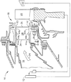
【図5】 本発明の例示的な実施形態によるノズルセグメントの製造の流れ図と組み合わせた、図2に示したノズルセグメントのうちの例示的な1つの分解組立図。
【図6】 図3のほぼ線6−6に沿って見た、隣り合うノズルセグメントの半径方向断面図。
【符号の説明】
10 ガスタービンエンジン
12 ファン
14 多段軸流圧縮機
16 燃焼器
18 高圧タービンノズル
20 高圧タービン
22 低圧タービン
26 支持リング
28 ステータ羽根
30 外側バンド
32 内側バンド
34 羽根前縁
36 羽根後縁
38 羽根の正圧面
40 羽根の負圧面
42a、44a 前方ランド
42b、44b 後方ランド
42c、44c 中間ランド
46 分割線
48 後方に面した段差
50 前方に面した段差[0001]
BACKGROUND OF THE INVENTION
The present invention relates generally to gas turbine engines, and more specifically to turbine nozzles for gas turbine engines.
[0002]
BACKGROUND OF THE INVENTION
In a gas turbine engine, air is pressurized in a compressor and mixed with fuel in a combustor to generate hot combustion gases that flow downstream through high pressure turbine nozzles, which are in contact with the gas. Direct the flow to the rotor blade row of the high pressure turbine. The blades extract energy from the gas and power the compressor, and a low-pressure turbine is located downstream of the blades, which further extracts energy and supplies power to the fan, typically this fan. Generates the propulsion that powers the aircraft in flight.
[0003]
Since the high pressure turbine nozzle receives the hottest combustion gas directly from the combustor, it is specially configured to withstand such hot gas for its useful life. The nozzle is an annular structure but is divided into arcuate segments to absorb the large expansion and contraction of its components due to the high temperature operating environment. Each segment includes an arcuate outer band and an inner band that support a pair of hollow stator vanes, which stator vanes are compressed air extracted from the compressor to cool the nozzle segments during operation. Receive a part.
[0004]
The two bands form a radially outer and inner channel surface that traps the combustion gases between them during operation. The bands are separated from each other by corresponding axial dividing lines, which are suitably sealed by a general spline seal between adjacent bands.
[0005]
The nozzle vane has a crescent shape with a substantial curvature or chamber between its leading and trailing edges and a generally convex suction surface opposite the generally concave pressure surface, and during operation the combustion gas is It flows along these surfaces. The suction surface of one blade is disposed circumferentially from the pressure surface of the adjacent blade, and a flow path for combustion gas is formed between both surfaces. Combustion gas enters these channels approximately axially downstream and is redirected at an oblique angle from a channel outlet formed between the trailing edges of adjacent vanes.
[0006]
Thus, the individual streamlines of the combustion gas flow substantially parallel to each other between the nozzle blades, but the degree of curvature changes depending on the different speeds caused by the pressure and suction surfaces of adjacent blades.
[0007]
The band dividing line is straight and is obliquely oriented within the band between the corresponding arcuate shapes of the pressure and suction surfaces of adjacent vanes. Accordingly, when the combustion gas is curved between the pressure surface and the suction surface and flows axially rearward along the dividing line, it generally crosses the dividing line twice while passing between the blades.
[0008]
The band is circumferentially continuous between each pair of vanes in each nozzle segment, thus providing maximum aerodynamic efficiency. However, the dividing line between the blades of adjacent nozzle segments provides local discontinuities within the band, which can affect aerodynamic efficiency.
[0009]
The flow surfaces of the bands are designed to be substantially coplanar with each other at the dividing line, but due to the normal manufacturing tolerances and the accumulation of these tolerances during assembly of the nozzle components, the radius of adjacent bands Irregular differences occur in the height of the direction, and a step corresponding to this is generated on the surface of the flow path. If the step faces forward in the direction opposite to the direction of the combustion gas, it becomes a local obstruction to the smooth flow of the combustion gas, reducing the aerodynamic efficiency of the nozzle and reducing the combustion gas. The edge that is exposed to is heated locally to oxidize it over time. Oxidation of the exposed parting line edge shortens the service life of the nozzle segment, necessitating replacement of the nozzle segment sooner than when the parting line edge is not exposed.
[0010]
As the combustion gas passes through the nozzle channel, the combustion gas typically crosses the diagonal dividing line twice, which can create a step that interferes with undesirable flow in the front part of the band or the rear part of the band. Alternatively, it is possible that undesired steps that impede flow in the transition region between these two parts may change. Since typical aircraft gas turbine engines operate at different power levels from idle to maximum power, the shape of the streamlines passing through the nozzles changes accordingly.
[0011]
Therefore, when the engine is in a certain operating state, the step facing in the downstream direction may change to the step facing in the upstream direction when the shape of the streamline changes. Undesirable oxidation of the upstream facing edge is still a practical problem because of the manufacturing tolerances and the inability to make nozzle components to the correct dimensions. ing. Therefore, the durability of the nozzle is affected by the exposed parting line edge that reduces the useful life of the nozzle in practice.
[0012]
Accordingly, it would be desirable to provide an improved turbine nozzle that includes an improved parting line configuration to increase nozzle durability and service life.
[Patent Document 1]
JP 2000-199402 A
[0013]
SUMMARY OF THE INVENTION
The turbine nozzle includes an outer band and an inner band segment that support a corresponding pair of vanes. These bands are adjacent to each other at corresponding ends along the dividing line, each band having a front land, a rear land opposite thereto, and an intermediate land extending between the two lands. The front land has a nominal step facing backward, the rear land has a nominal step facing forward, and the intermediate land is nominally coplanar.
[0014]
DETAILED DESCRIPTION OF THE INVENTION
In accordance with the preferred exemplary embodiments, the invention and further objects and advantages thereof will be described in further detail in the following detailed description made in conjunction with the accompanying drawings.
[0015]
FIG. 1 schematically illustrates a
[0016]
During operation, air flows through the fan and compressor and is mixed with fuel in the combustor to produce
[0017]
The high-
[0018]
As shown in FIG. 2, each nozzle segment includes a pair of
[0019]
The
[0020]
As shown in FIGS. 2 and 3, each of the inner bands has first and
[0021]
As will be described further below, the
[0022]
More specifically, the dividing
[0023]
As mentioned above, due to the stacking of manufacturing tolerances of nozzle components and tolerances during assembly, undesirable upstream-facing steps are irregularly formed at the joints of the nozzle bands at the corresponding dividing lines. This upstream-facing step locally blocks the downstream flow of combustion gas, causing local heating and oxidation, which can reduce nozzle efficiency and shorten its service life There is.
[0024]
However, according to the present invention, the joint of the nozzle band in the corresponding dividing line is specially configured to reduce or eliminate irregular effects due to the step facing upstream, improve nozzle efficiency, and in the dividing line Reduce the oxidation and extend the service life of the nozzle.
[0025]
More specifically, referring to FIG. 3, each of the band end portions includes
[0026]
According to the present invention, adjacent
[0027]
As mentioned above, the manufacture of turbine components is not possible to achieve complete or accurate dimensions and is therefore accompanied by irregular variations in the dimensions. As will be described below, the various components of the turbine nozzle are first cast, assembled together, and brazed into two-blade nozzle segments that are connected to the
[0028]
The final radial position of the inner and outer band channel surfaces is determined by the manufacturing tolerances of the band itself, the assembly tolerances when coupled to the vanes, and the assembly tolerances when attached to the
[0029]
In the manufacture and assembly of conventional turbine nozzle components, the radial position of the inner and outer band flow surface at the parting line can be within a dimensional tolerance range of about ± 20 mils. For conventional turbine nozzles designed so that the final position of the band edge is nominally coplanar, the irregular variation in dimensional tolerances creates large forward or backward facing steps, which are the combustion gas This can locally impede the flow of gas and thereby locally heat and oxidize, reducing the useful life of the turbine nozzle.
[0030]
However, according to the present invention, the rear-facing
[0031]
Similarly, the
[0032]
The
[0033]
As best shown in FIG. 3, the dividing
[0034]
When the
[0035]
Thus, over the preferred operating range of the engine, e.g., up to the cruise and idling outputs or up to the maximum output, if necessary, the combustion gas streamline is preferably at a
[0036]
For example, if the intermediate land is omitted and the rear land and the front land are connected to each other in the vicinity of the middle of the dividing line, the streamline that flows along the right band after passing through the blade leading edge shown in FIG. Some of them may hit a rear-facing step when changing direction quickly beyond the dividing line. Alternatively, a part of the stream line from the left band may change a direction lately beyond the dividing line and hit a part of the step facing forward.
[0037]
By introducing intermediate lands that are substantially coplanar with each other, the flow that changes direction quickly or slowly between the blades, instead of flowing in the downstream direction across the steps facing the front and rear, upstream direction Reduce the risk of flowing into
[0038]
In the preferred embodiment shown in FIGS. 3 and 4, the front lands and the rear lands smoothly transition to the corresponding intermediate lands, and the
[0039]
As shown schematically in FIG. 4, the front lands 44a (+) of the left band are higher than the
[0040]
The heights B and C of these two steps are reduced in size from the front and rear ends of the band facing toward the intermediate land between them, so that the height between the front land and the rear land is reduced. It is preferable to move slowly so that the difference is substantially zero so that a nominal coplanar alignment is obtained between them.
[0041]
In the exemplary embodiment shown in FIG. 3, the
[0042]
The introduction of the
[0043]
In view of the manufacturing tolerances and the nature of the stacking of them, the final position of the channel surface at the dividing line becomes irregular, so the introduction of three different front lands, rear lands and intermediate lands along the dividing line Can be advantageously used to reduce the tendency and extent of excessive oxidation that protrudes into the portion of the combustion gas stream, locally increases the temperature of the edge and shortens the life of the nozzle.
[0044]
Nozzle line edge oxidation is reduced by careful and selective introduction of a rearward facing
[0045]
However, according to another feature of the present invention, the
[0046]
FIG. 5 schematically illustrates a preferred method for making individual nozzle segments that together form an annular turbine nozzle.
[0047]
In this method, the mold corresponds to the outer surfaces of the blades and bands and is first filled with wax. The wax is solidified and removed from the mold and then coated with ceramic to form a cast shell. Wax is removed from the cast shell and replaced with molten metal, which forms the corresponding part. Since the vanes are preferably hollow, a conventional ceramic core is used with a ceramic shell for casting the vanes in any conventional manner.
[0048]
The cast vanes and bands are then assembled together by inserting the corresponding opposite hub ends of the vanes into the corresponding seats in the band and temporarily held in a suitable fixture in that state.
[0049]
The vane hub is then brazed into the corresponding seat in the band and the two cast vanes and the two bands are fixedly joined together to form a four-part assembly for each nozzle segment. The Each nozzle segment is then processed such that the blades are perforated with various rows of film cooling holes and additional features are added to complete the nozzle segment row that forms the finished turbine nozzle. Is done.
[0050]
In a preferred embodiment, a pair of nozzle segments is thus manufactured using the same master mold for the vanes and bands, and then their intended relative position within the turbine nozzle. To this end, the two nozzle segments are assembled together in a suitable fixture or are assembled together on the intended
[0051]
In conventional casting operations for turbine nozzle parts, the master mold is configured to obtain the nominal dimensions of the corresponding vane and band parts, thus resulting in irregular variations in dimensions, which can result in precise tolerances. Compared to machined parts that can reduce the variability at the same time, the casting parts are considerably larger. The casting tolerances of the nozzle parts and the tolerances that accumulate when assembling them generally cause irregular variations in the relative height between adjacent
[0052]
As a result, the desired coplanarity between adjacent intermediate lands changes within the corresponding tolerance range, resulting in a local small initial intermediate step having a magnitude D. This intermediate step D is measured when two adjacent nozzle segments are correctly fixed in relative positions. Then, another pair of nozzle segments is preferably recast to reduce the measured step D to obtain the desired nominal coplanar alignment between adjacent intermediate lands.
[0053]
More specifically, FIG. 6 shows the relevant part of the
[0054]
Casting the sample nozzle segments, assembling them, measuring the height difference between the intermediate lands, polishing the band mold locally, and recasting a new set of nozzle segments To reduce or substantially eliminate the step D, it can be performed one or more desired times. Thus, the resulting inner band will only have a thickness difference at their parting line to obtain a nominally coplanar alignment between them. As shown in FIG. 6, in the left
[0055]
Since the
[0056]
As described above, the configuration in which three lands are provided along the dividing line is preferably introduced into both the inner band and the outer band, so that the mold for them likewise has a corresponding rear-facing step. In order to obtain the desired coplanarity in the intermediate lands between adjacent inner and outer bands where the step facing forward is gradually shifted, it can be polished as locally as necessary.
[0057]
As shown schematically in FIG. 5, the cast
[0058]
In the preferred embodiment shown in FIG. 5, the corresponding
[0059]
Furthermore, the brazed nozzle segments are fixed at three points as described above, and two corresponding mounting
[0060]
In spite of the conventional manufacturing tolerances and their stacking as described above, the adjacent inner and outer bands of the nozzle segments have a rear-facing step on the front land and a front-facing step on the rear land. With a substantially coplanar intermediate land between the two, and the turbine nozzle aerodynamics without locally obstructing the flow of combustion gas by the protruding dividing line edges Efficiency can be maximized. The parting line edge is protected from the combustion gas and is therefore not further heated and oxidized as if protruding into the combustion gas stream. Therefore, the durability of the turbine nozzle is improved and its service life is increased accordingly.
[0061]
While this specification has described what is considered to be a preferred exemplary embodiment of the present invention, other variations of the present invention will be apparent to those skilled in the art from the teachings herein. The reference signs in the claims are for easy understanding and do not limit the technical scope of the invention to the embodiments.
[Brief description of the drawings]
FIG. 1 is an axial cross-sectional view of a portion of a turbofan aircraft gas turbine engine including a combustor that discharges combustion gas to a high pressure turbine nozzle, according to an illustrative embodiment of the invention.
FIG. 2 is a perspective view of a part of the turbine nozzle shown in FIG.
FIG. 3 is a radial cross-sectional view of a portion of adjacent nozzle segments as viewed along line 3-3 of FIG.
4 is a cross-sectional view of a portion of adjacent inner bands of nozzle segments, taken generally along line 4-4 of FIG.
FIG. 5 is an exploded view of an exemplary one of the nozzle segments shown in FIG. 2 in combination with a nozzle segment manufacturing flow diagram according to an exemplary embodiment of the present invention.
6 is a radial cross-sectional view of adjacent nozzle segments, taken generally along line 6-6 of FIG.
[Explanation of symbols]
10 Gas turbine engine
12 fans
14 Multistage axial compressor
16 Combustor
18 High pressure turbine nozzle
20 High-pressure turbine
22 Low pressure turbine
26 Support ring
28 Stator blade
30 Outer band
32 inner band
34 Blade leading edge
36 Feather trailing edge
38 Blade pressure surface
40 vane suction surface
42a, 44a Front land
42b, 44b Rear land
42c, 44c Intermediate land
46 dividing line
48 Steps facing backward
50 Steps facing forward
Claims (8)
前記羽根の各々が、軸方向に対向する前縁及び後縁(34、36)と、前記対向する端部の間で半径方向に延び、円周方向に対向する正圧及び負圧面(38、40)とを有し、
前記バンドの各々が、それらの間のそれぞれの分割線(46)において隣り合い、円周方向に対向する第1及び第2の端部(42、44)を有し、
前記バンド端部の各々が、前記羽根前縁付近で前記分割線に沿って延びる前方ランド(42a、44a)と、前記羽根後縁付近で前記分割線に沿って延びる後方ランド(42b、44b)と、前記前方ランドと後方ランドとの間で前記羽根の中間部分にわたって前記分割線に沿って延びる、単一の点ではない中間ランド(42c、44c)とを有し、これらのランドが集合して前記羽根の間に燃焼ガス流の境界となる流路表面を形成し、
前記分割線(46)が前記セグメントの間に斜めに配置され、
前記前方ランドが前記分割線において、前記一対の羽根間を通る流体の上流側が下流側よりも高くなるような、後方に面した公称段差(48)を有し、前記後方ランドが前記分割線において、前記流体の上流側が下流側よりも高くなるような、前方に面した公称段差(50)を有し、前記中間ランドが公称同一平面になっている、
ことを特徴とするタービンノズル(18)。Comprising a row of nozzle segments (18a) with a pair of vanes (28) attached to the outer and inner bands (30, 32) at the ends;
Each of the vanes extends radially between the axially opposed leading and trailing edges (34, 36) and the opposed ends, and circumferentially opposed positive and negative pressure surfaces (38, 40)
Each of the bands has first and second ends (42, 44) that are adjacent and circumferentially opposed at a respective dividing line (46) therebetween,
Each of the band ends has a front land (42a, 44a) extending along the dividing line near the leading edge of the blade and a rear land (42b, 44b) extending along the dividing line near the trailing edge of the blade. And intermediate lands (42c, 44c) that are not a single point and extend along the dividing line across the intermediate portion of the blade between the front land and the rear land. Forming a flow path surface serving as a boundary of the combustion gas flow between the blades,
The dividing lines (46) are arranged diagonally between the segments;
The front land has a nominal step (48) facing rearward so that the upstream side of the fluid passing between the pair of blades is higher than the downstream side in the dividing line, and the rear land is in the dividing line A nominal step (50) facing forward, such that the upstream side of the fluid is higher than the downstream side , and the intermediate lands are nominally coplanar;
A turbine nozzle (18) characterized in that.
前記羽根(28)とバンド(30、32)とを別々に鋳造する段階と、
前記鋳造された羽根とバンドとを互いに結合して1対の前記ノズルセグメント(18a)を形成する段階と、
該1対のノズルセグメントを互いに組み立てる段階と、
前記中間ランド(42c、44c)の間の全ての段差を測定する段階と、
前記中間ランドにおける前記公称同一平面の整合に対する前記測定された段差を減少させるために、別の対の前記ノズルセグメントを再鋳造する段階と、
を含むことを特徴とする方法。A method of making a nozzle (18) according to claim 1, comprising:
Casting the vane (28) and the bands (30, 32) separately;
Joining the cast blades and bands together to form a pair of the nozzle segments (18a);
Assembling the pair of nozzle segments together;
Measuring all steps between the intermediate lands (42c, 44c);
Re-casting another pair of the nozzle segments to reduce the measured step to the nominal coplanar alignment in the intermediate land;
A method comprising the steps of:
前記測定された段差を減少させるために、前記中間ランドのうちの対応する中間ランドの厚さを局部的に増大させるように、前記バンド鋳型(32M)のうちの1つを局部的に研磨して、それから材料を除去する段階と、
前記測定された段差を減少させるために、前記研磨されたバンド鋳型を用いて、前記セグメントを再鋳造する段階と、
を更に含むことを特徴とする、請求項5に記載の方法。Casting said vanes (28) and bands (30, 32) with corresponding molds (28M, 30M, 32M) for them;
In order to reduce the measured step, one of the band molds (32M) is locally polished so as to locally increase the thickness of the corresponding intermediate land of the intermediate lands. And then removing the material,
Re-casting the segment using the polished band mold to reduce the measured step;
The method of claim 5, further comprising:
前記固定されたバンドに前記羽根(28)を互いに結合する段階と、
を更に含むことを特徴とする、請求項6に記載の方法。Securing the cast outer and inner bands (30, 32) at three points, each on its flow surface;
Coupling the vanes (28) to the fixed band together;
The method of claim 6, further comprising:
Applications Claiming Priority (2)
| Application Number | Priority Date | Filing Date | Title |
|---|---|---|---|
| US09/916,352 US6579061B1 (en) | 2001-07-27 | 2001-07-27 | Selective step turbine nozzle |
| US09/916352 | 2001-07-27 |
Publications (3)
| Publication Number | Publication Date |
|---|---|
| JP2003106104A JP2003106104A (en) | 2003-04-09 |
| JP2003106104A5 JP2003106104A5 (en) | 2005-10-27 |
| JP4183996B2 true JP4183996B2 (en) | 2008-11-19 |
Family
ID=25437131
Family Applications (1)
| Application Number | Title | Priority Date | Filing Date |
|---|---|---|---|
| JP2002215927A Expired - Fee Related JP4183996B2 (en) | 2001-07-27 | 2002-07-25 | Selected turbine nozzle with step |
Country Status (4)
| Country | Link |
|---|---|
| US (1) | US6579061B1 (en) |
| EP (1) | EP1279796B1 (en) |
| JP (1) | JP4183996B2 (en) |
| DE (1) | DE60210377T2 (en) |
Cited By (1)
| Publication number | Priority date | Publication date | Assignee | Title |
|---|---|---|---|---|
| JP2016205390A (en) * | 2015-04-22 | 2016-12-08 | ゼネラル・エレクトリック・カンパニイ | Methods for positioning neighboring nozzles of gas turbine engine |
Families Citing this family (28)
| Publication number | Priority date | Publication date | Assignee | Title |
|---|---|---|---|---|
| US7114920B2 (en) * | 2004-06-25 | 2006-10-03 | Pratt & Whitney Canada Corp. | Shroud and vane segments having edge notches |
| US7441331B2 (en) * | 2004-08-26 | 2008-10-28 | United Technologies Corporation | Turbine engine component manufacture methods |
| US7195454B2 (en) * | 2004-12-02 | 2007-03-27 | General Electric Company | Bullnose step turbine nozzle |
| US7249928B2 (en) * | 2005-04-01 | 2007-07-31 | General Electric Company | Turbine nozzle with purge cavity blend |
| EP1790826A1 (en) * | 2005-11-24 | 2007-05-30 | Siemens Aktiengesellschaft | Turbine vane for a turbine of a thermal power plant |
| US7762761B2 (en) * | 2005-11-30 | 2010-07-27 | General Electric Company | Methods and apparatus for assembling turbine nozzles |
| US7377743B2 (en) * | 2005-12-19 | 2008-05-27 | General Electric Company | Countercooled turbine nozzle |
| US8281604B2 (en) * | 2007-12-17 | 2012-10-09 | General Electric Company | Divergent turbine nozzle |
| US8459956B2 (en) * | 2008-12-24 | 2013-06-11 | General Electric Company | Curved platform turbine blade |
| US8439643B2 (en) * | 2009-08-20 | 2013-05-14 | General Electric Company | Biformal platform turbine blade |
| JP5426305B2 (en) * | 2009-09-30 | 2014-02-26 | 株式会社東芝 | Turbo machine |
| US8622692B1 (en) * | 2010-12-13 | 2014-01-07 | Florida Turbine Technologies, Inc. | High temperature turbine stator vane |
| FR2974593B1 (en) * | 2011-04-28 | 2015-11-13 | Snecma | TURBINE ENGINE COMPRISING A METAL PROTECTION OF A COMPOSITE PIECE |
| US9447689B2 (en) | 2011-06-17 | 2016-09-20 | General Electric Company | Method of repairing a turbine nozzle segment in a turbine engine |
| US9194235B2 (en) | 2011-11-25 | 2015-11-24 | Mtu Aero Engines Gmbh | Blading |
| US9267386B2 (en) | 2012-06-29 | 2016-02-23 | United Technologies Corporation | Fairing assembly |
| EP2885506B8 (en) | 2012-08-17 | 2021-03-31 | Raytheon Technologies Corporation | Contoured flowpath surface |
| US20140154068A1 (en) * | 2012-09-28 | 2014-06-05 | United Technologies Corporation | Endwall Controuring |
| US10364690B2 (en) * | 2013-02-22 | 2019-07-30 | United Technologies Corporation | Stator vane assembly and method therefor |
| EP3095550A1 (en) | 2015-05-20 | 2016-11-23 | Rolls-Royce Corporation | Pre-sintered preform braze for joining alloy castings and use thereof |
| EP3260663B1 (en) * | 2016-06-21 | 2020-07-29 | General Electric Technology GmbH | Axial flow turbine diaphragm construction |
| US10738700B2 (en) | 2016-11-16 | 2020-08-11 | General Electric Company | Turbine assembly |
| US10480333B2 (en) * | 2017-05-30 | 2019-11-19 | United Technologies Corporation | Turbine blade including balanced mateface condition |
| US11090771B2 (en) | 2018-11-05 | 2021-08-17 | Rolls-Royce Corporation | Dual-walled components for a gas turbine engine |
| US11305363B2 (en) | 2019-02-11 | 2022-04-19 | Rolls-Royce Corporation | Repair of through-hole damage using braze sintered preform |
| US20210079799A1 (en) * | 2019-09-12 | 2021-03-18 | General Electric Company | Nozzle assembly for turbine engine |
| US11692446B2 (en) | 2021-09-23 | 2023-07-04 | Rolls-Royce North American Technologies, Inc. | Airfoil with sintered powder components |
| US11885498B2 (en) * | 2022-01-31 | 2024-01-30 | General Electric Company | Turbine engine with fuel system including a catalytic reformer |
Family Cites Families (9)
| Publication number | Priority date | Publication date | Assignee | Title |
|---|---|---|---|---|
| FR2166494A5 (en) * | 1971-12-27 | 1973-08-17 | Onera (Off Nat Aerospatiale) | |
| US4135857A (en) | 1977-06-09 | 1979-01-23 | United Technologies Corporation | Reduced drag airfoil platforms |
| GB2042675A (en) * | 1979-02-15 | 1980-09-24 | Rolls Royce | Secondary Flow Control in Axial Fluid Flow Machine |
| JPS58162702A (en) | 1982-03-23 | 1983-09-27 | Mitsubishi Heavy Ind Ltd | Axial flow type turbomachine |
| US5020970A (en) * | 1989-07-13 | 1991-06-04 | Dresser-Rand Company | Fluid-handling, bladed rotor |
| EP1260678B1 (en) * | 1997-09-15 | 2004-07-07 | ALSTOM Technology Ltd | Segment arrangement for platforms |
| JPH11193701A (en) | 1997-10-31 | 1999-07-21 | General Electric Co <Ge> | Turbine wing |
| US6158961A (en) * | 1998-10-13 | 2000-12-12 | General Electric Compnay | Truncated chamfer turbine blade |
| US6354797B1 (en) * | 2000-07-27 | 2002-03-12 | General Electric Company | Brazeless fillet turbine nozzle |
-
2001
- 2001-07-27 US US09/916,352 patent/US6579061B1/en not_active Expired - Fee Related
-
2002
- 2002-07-19 EP EP02255071A patent/EP1279796B1/en not_active Expired - Lifetime
- 2002-07-19 DE DE60210377T patent/DE60210377T2/en not_active Expired - Lifetime
- 2002-07-25 JP JP2002215927A patent/JP4183996B2/en not_active Expired - Fee Related
Cited By (2)
| Publication number | Priority date | Publication date | Assignee | Title |
|---|---|---|---|---|
| JP2016205390A (en) * | 2015-04-22 | 2016-12-08 | ゼネラル・エレクトリック・カンパニイ | Methods for positioning neighboring nozzles of gas turbine engine |
| US10018075B2 (en) | 2015-04-22 | 2018-07-10 | General Electric Company | Methods for positioning neighboring nozzles of a gas turbine engine |
Also Published As
| Publication number | Publication date |
|---|---|
| EP1279796A2 (en) | 2003-01-29 |
| JP2003106104A (en) | 2003-04-09 |
| US6579061B1 (en) | 2003-06-17 |
| DE60210377D1 (en) | 2006-05-18 |
| EP1279796A3 (en) | 2003-12-03 |
| EP1279796B1 (en) | 2006-04-05 |
| DE60210377T2 (en) | 2007-03-29 |
| US20030113206A1 (en) | 2003-06-19 |
Similar Documents
| Publication | Publication Date | Title |
|---|---|---|
| JP4183996B2 (en) | Selected turbine nozzle with step | |
| JP4785507B2 (en) | Turbine nozzle with bull nose step | |
| US6354797B1 (en) | Brazeless fillet turbine nozzle | |
| EP2071126B1 (en) | Turbine blades and methods of manufacturing | |
| JP4311919B2 (en) | Turbine airfoils for gas turbine engines | |
| JP4152184B2 (en) | Turbine platform with descending stage | |
| US8851846B2 (en) | Apparatus and methods for cooling platform regions of turbine rotor blades | |
| EP1088964A2 (en) | Slotted impingement cooling of airfoil leading edge | |
| JP4100916B2 (en) | Nozzle fillet rear cooling | |
| JP4245873B2 (en) | Turbine airfoils for gas turbine engines | |
| EP3294994B1 (en) | Gas turbine guide vane segment and method of manufacturing | |
| JP2003201805A (en) | Airfoil part for turbine nozzle of gas turbine engine and its manufacturing method | |
| US8628300B2 (en) | Apparatus and methods for cooling platform regions of turbine rotor blades | |
| US6158961A (en) | Truncated chamfer turbine blade | |
| US11333042B2 (en) | Turbine blade with dust tolerant cooling system | |
| EP3498971B1 (en) | Aerofoil for a gas turbine engine comprising a dividing sheet | |
| US11391161B2 (en) | Component for a turbine engine with a cooling hole | |
| JP2017141823A (en) | Thermal stress relief of component | |
| US10655485B2 (en) | Stress-relieving pocket in turbine nozzle with airfoil rib | |
| US6439837B1 (en) | Nozzle braze backside cooling | |
| GB2366599A (en) | Air-cooled turbine blade | |
| EP3677750B1 (en) | Gas turbine engine component with a trailing edge discharge slot | |
| JP2020180616A (en) | Turbocharger | |
| CA3133761A1 (en) | Turbine engine vane equipped with a cooling circuit and lost-wax method for manufacturing such a vane |
Legal Events
| Date | Code | Title | Description |
|---|---|---|---|
| A521 | Written amendment |
Free format text: JAPANESE INTERMEDIATE CODE: A523 Effective date: 20050720 |
|
| A621 | Written request for application examination |
Free format text: JAPANESE INTERMEDIATE CODE: A621 Effective date: 20050720 |
|
| A131 | Notification of reasons for refusal |
Free format text: JAPANESE INTERMEDIATE CODE: A131 Effective date: 20080205 |
|
| A521 | Written amendment |
Free format text: JAPANESE INTERMEDIATE CODE: A523 Effective date: 20080502 |
|
| TRDD | Decision of grant or rejection written | ||
| A01 | Written decision to grant a patent or to grant a registration (utility model) |
Free format text: JAPANESE INTERMEDIATE CODE: A01 Effective date: 20080812 |
|
| A01 | Written decision to grant a patent or to grant a registration (utility model) |
Free format text: JAPANESE INTERMEDIATE CODE: A01 |
|
| A61 | First payment of annual fees (during grant procedure) |
Free format text: JAPANESE INTERMEDIATE CODE: A61 Effective date: 20080903 |
|
| FPAY | Renewal fee payment (event date is renewal date of database) |
Free format text: PAYMENT UNTIL: 20110912 Year of fee payment: 3 |
|
| R150 | Certificate of patent or registration of utility model |
Free format text: JAPANESE INTERMEDIATE CODE: R150 |
|
| FPAY | Renewal fee payment (event date is renewal date of database) |
Free format text: PAYMENT UNTIL: 20110912 Year of fee payment: 3 |
|
| FPAY | Renewal fee payment (event date is renewal date of database) |
Free format text: PAYMENT UNTIL: 20120912 Year of fee payment: 4 |
|
| FPAY | Renewal fee payment (event date is renewal date of database) |
Free format text: PAYMENT UNTIL: 20130912 Year of fee payment: 5 |
|
| R250 | Receipt of annual fees |
Free format text: JAPANESE INTERMEDIATE CODE: R250 |
|
| LAPS | Cancellation because of no payment of annual fees |