JP4181981B2 - toner - Google Patents
toner Download PDFInfo
- Publication number
- JP4181981B2 JP4181981B2 JP2003418393A JP2003418393A JP4181981B2 JP 4181981 B2 JP4181981 B2 JP 4181981B2 JP 2003418393 A JP2003418393 A JP 2003418393A JP 2003418393 A JP2003418393 A JP 2003418393A JP 4181981 B2 JP4181981 B2 JP 4181981B2
- Authority
- JP
- Japan
- Prior art keywords
- toner
- parts
- molecular weight
- mass
- particles
- Prior art date
- Legal status (The legal status is an assumption and is not a legal conclusion. Google has not performed a legal analysis and makes no representation as to the accuracy of the status listed.)
- Expired - Fee Related
Links
Images


Landscapes
- Dry Development In Electrophotography (AREA)
- Developing Agents For Electrophotography (AREA)
Description
本発明は電子写真法、静電記録法等を利用した記録方法に用いられるトナー、現像装置、プロセスカートリッジ及び画像形成方法に関するものである。詳しくは、予め静電潜像担持体上に現像剤像を形成後、転写材上に転写させて画像形成する複写機、プリンター、ファックス等の画像形成装置に用いられるトナー、現像装置、プロセスカートリッジ及び画像形成方法に関する。 The present invention relates to a toner, a developing device, a process cartridge, and an image forming method used in a recording method using an electrophotographic method, an electrostatic recording method, or the like. Specifically, a toner, a developing device, and a process cartridge that are used in an image forming apparatus such as a copying machine, a printer, and a fax machine that forms a developer image on an electrostatic latent image carrier in advance and then transfers the image onto a transfer material to form an image. And an image forming method.
近年、電子写真法を用いた機器は、従来の複写機に加え、例えば、プリンターやファックスのごとき装置に適用されている。特にプリンターやファックスでは複写装置部分を小さくする必要や、メンテナンスを容易にする為、現像装置を中心とした現像剤ユニットと静電潜像担持体を中心としたドラムユニットの二つのユニット化や、さらにそれらを一体化したプロセスカートリッジを用いることが多くなってきた。 In recent years, apparatuses using electrophotography have been applied to apparatuses such as printers and fax machines in addition to conventional copying machines. Especially for printers and fax machines, it is necessary to reduce the size of the copying machine, and to make maintenance easier, the developer unit centered on the developing device and the drum unit centered on the electrostatic latent image carrier, A process cartridge in which they are integrated has been increasingly used.
そしてこれらのプロセスカートリッジに用いられる現像方式としては、小型化に有利な一成分現像方式が多い。一成分現像方式は、一成分現像剤(以下「トナー」とも呼ぶ)を使用し、層厚規制部材(以下「ブレード」とも呼ぶ)とトナー粒子の摩擦、及び現像剤担持体(以下「現像ローラ」とも呼ぶ)とトナー粒子の摩擦によりトナー粒子に電荷を与えると同時に現像ローラ上に薄く塗布し、現像ローラと静電潜像担持体とが対向した現像領域にトナーを搬送し、静電潜像担持体上の静電潜像を現像し、トナー画像として顕像化する。 As a developing method used for these process cartridges, there are many one-component developing methods advantageous for downsizing. The one-component developing method uses a one-component developer (hereinafter also referred to as “toner”), friction between a layer thickness regulating member (hereinafter also referred to as “blade”) and toner particles, and a developer carrier (hereinafter referred to as “developing roller”). Is also applied to the developing roller at the same time as a thin film on the developing roller by friction of the toner particles, and the toner is transported to a developing area where the developing roller and the electrostatic latent image carrier face each other. The electrostatic latent image on the image carrier is developed and visualized as a toner image.
この一成分現像方式は、ガラスビーズや鉄粉、フェライト等のキャリア粒子が必要な二成分現像方式とは異なり、キャリア粒子が不要のため、現像装置自体を小型化、軽量化できる。さらに二成分現像方式は、現像剤中のトナー濃度を一定に保つ必要があるため、トナー濃度を検知し必要量のトナーを補給する装置が必要であり、現像装置の大型化、重量化を招くのに対し、一成分現像方式にはその必要は無い。この点において一成分現像方式は小型化、軽量化に有利である。更に、一般的には有色である磁性紛をフルカラー用現像剤に内包化せしめて用いることは、色再現性の観点から困難である。こうしたことから、現像剤として非磁性トナーを用いることが広く行われている。 Unlike the two-component development method that requires carrier particles such as glass beads, iron powder, and ferrite, this one-component development method does not require carrier particles, and thus the development apparatus itself can be reduced in size and weight. Furthermore, since the two-component development method needs to keep the toner concentration in the developer constant, a device that detects the toner concentration and replenishes the necessary amount of toner is required, which leads to an increase in the size and weight of the developing device. On the other hand, there is no need for the one-component development method. In this respect, the one-component development method is advantageous for reduction in size and weight. Furthermore, it is difficult from the viewpoint of color reproducibility to use a magnetic powder which is generally colored in a full color developer. For these reasons, the use of nonmagnetic toner as a developer is widely performed.
また近年では静電潜像担持体と現像ローラを直接又は間接的に接触させ、静電潜像担持体にトナー層を接触させて現像を行う接触現像法も広く行われている。接触現像法は細線再現性、画像濃度均一性等に優れた現像方法であり、高画質化を達成する手段として好ましいものである。 In recent years, a contact development method has been widely used in which development is performed by bringing an electrostatic latent image carrier and a developing roller into direct or indirect contact with each other and bringing a toner layer into contact with the electrostatic latent image carrier. The contact development method is a development method excellent in fine line reproducibility, image density uniformity and the like, and is preferable as a means for achieving high image quality.
こうした従来技術によって、マシンの小型化、高画質化、フルカラー化、イージーメンテナンス化等についての項目は達成されてきたが、近年これらに加え、高速印刷、消費電力の低減等の項目についての更なる性能アップが必要とされるようになってきた。これらの性能を達成させるためにはトナーの分子量を小さめにする方法が有効であることが、一般に広く知られている。 With these conventional technologies, items such as machine downsizing, higher image quality, full color, and easy maintenance have been achieved, but in recent years, in addition to these, further items such as high-speed printing and reduced power consumption have been achieved. There has been a need for improved performance. In order to achieve these performances, it is generally well known that a method of reducing the molecular weight of the toner is effective.
しかしながら、静電潜像担持体と現像ローラが直接又は間接的に当接して現像を行うと、現像時にトナー粒子にかかる応力は大きくなる。その結果、トナー粒子の粉砕、変形等が起こり、トナーの帯電特性が劣化して高品位の画像を得ることが困難となる。具体的には低温低湿度環境において、粉砕、変形により小粒径化したトナーが過剰な帯電特性を有し、静電潜像担持体との静電引力が設定値以上となってしまう。その結果、転写およびクリーニング工程においてもこれら小粒径トナーを静電潜像担持体表面より取り除くことができず、新たな潜像を形成する妨げとなり、いわゆるネガゴースト画像を発生してしまうため、問題となっていた。 However, when development is performed with the electrostatic latent image carrier and the developing roller in direct or indirect contact, the stress applied to the toner particles during development increases. As a result, the toner particles are crushed, deformed, etc., and the charging characteristics of the toner are deteriorated, making it difficult to obtain a high-quality image. Specifically, in a low-temperature and low-humidity environment, the toner that has been reduced in particle size by pulverization and deformation has excessive charging characteristics, and the electrostatic attractive force with the electrostatic latent image carrier becomes equal to or greater than a set value. As a result, even in the transfer and cleaning steps, these small particle size toners cannot be removed from the surface of the electrostatic latent image carrier, hindering the formation of a new latent image, and so-called negative ghost images are generated. It was a problem.
この現象を抑制する手段としては、トナー粒子を球形化し、劣化を抑える方法(例えば特許文献1参照)がある。しかしながら本発明者らがこれらの従来技術を用いて鋭意検討した結果、ネガゴースト画像の発生を抑制する効果は不十分であることが判明した。この結果を受け、本発明者らは、トナー劣化を効果的に抑制するためにはトナーの分子量分布および架橋成分含有率についても好適なものとすることが重要と考え、引き続き検討を行った。(これらの物性を規定したものとして、例えば特許文献2および3を参照。)しかしながら、これらの技術はトナーの定着性向上という点においては優れていたが、ネガゴースト画像の発生を抑制することはできなかった。
本発明は、低温低湿度条件下において現像容器内でトナーが粉砕、変形し小粒径化することによって発生するゴースト画像を効果的に抑制するトナー、現像装置、およびプロセスカートリッジを提供することを目的とする。 The present invention provides a toner, a developing device, and a process cartridge that effectively suppress a ghost image generated by pulverizing, deforming, and reducing the particle size in a developing container under low temperature and low humidity conditions. Objective.
また、本発明は低温低湿度条件下において現像容器内でトナーが粉砕、変形し小粒径化することによって発生するゴースト画像を効果的に抑制する画像形成方法を提供することを目的とする。 It is another object of the present invention to provide an image forming method that effectively suppresses a ghost image generated by pulverizing, deforming, and reducing the particle size in a developing container under a low temperature and low humidity condition.
上記の目的は以下の本発明によって達成される。 The above object is achieved by the present invention described below.
すなわち本発明は、水系媒体中に分散する重合体微粒子を複数個凝集合一させることにより得られるトナー粒子を有するトナーであって、該トナーは体積平均粒径が4〜10μmであり、形状係数SF−1が115〜140であり、平均円形度が0.950〜0.990であり、BET比表面積が1.5〜7.0m2/gであり、トルエン可溶成分のゲルパーミネーションクロマトグラフィー(GPC)測定で、横軸を分子量の対数表示としたGPCチャートにおいて、分子量3000以上45000未満の領域に少なくとも1つのピークを有し、メインピークの1/2高さでベースラインと水平に線を引き、メインピーク分子量(Mp)より低分子量成分の直線長さをLa、Mpより高分子量成分の直線長さをLbとしたときに関係式(1)が成り立ち、分子量3000以上の領域の分子量積分値において、Mpより低分子量成分の積分値をSa、Mpより高分子量成分の積分値をSbとしたときに関係式(2)が成り立つことを特徴とするトナー、該トナーを用いた現像装置、該トナーを用いたプロセスカートリッジ、および該トナーを用いた画像形成方法に関する。
That is, the present invention relates to a toner having toner particles obtained by aggregating and coalescing a plurality of polymer fine particles dispersed in an aqueous medium, and the toner has a volume average particle size of 4 to 10 μm and a shape factor. SF-1 is 115 to 140, average circularity is 0.950 to 0.990, BET specific surface area is 1.5 to 7.0 m 2 / g, and toluene-soluble component gel permeation chromatography In the GPC chart in which the horizontal axis is the logarithm of molecular weight in the graph (GPC) measurement, the GPC chart has at least one peak in the region of molecular weight of 3000 or more and less than 45000, and is parallel to the baseline at 1/2 the height of the main peak. When a line is drawn and the linear length of the low molecular weight component from the main peak molecular weight (Mp) is La and the linear length of the high molecular weight component from Mp is Lb, the relational expression (1) is established and the
以上説明してきたように、本発明によれば、低温低湿度条件下においてもゴースト画像を効果的に抑制するトナー、現像装置、およびプロセスカートリッジを提供することができる。 As described above, according to the present invention, it is possible to provide a toner, a developing device, and a process cartridge that can effectively suppress a ghost image even under a low temperature and low humidity condition.
また、本発明によれば、低温低湿度条件下においてもゴースト画像を効果的に抑制する画像形成方法を提供することができる。 In addition, according to the present invention, it is possible to provide an image forming method that effectively suppresses a ghost image even under a low temperature and low humidity condition.
本発明者らが鋭意検討を行った結果、下記に示すトナー、すなわち、水系媒体中に分散する重合体微粒子を複数個凝集合一させることにより得られるトナー粒子を有するトナーであって、該トナーは体積平均粒径が4〜10μmであり、形状係数SF−1が115〜140であり、平均円形度が0.950〜0.990であり、BET比表面積が1.5〜7.0m2/gであり、トルエン可溶成分のゲルパーミネーションクロマトグラフィー(GPC)測定で、横軸を分子量の対数表示としたGPCチャートにおいて、分子量3000以上45000未満の領域に少なくとも1つのピークを有し、メインピークの1/2高さでベースラインと水平に線を引き、メインピーク分子量(Mp)より低分子量成分の直線長さをLa、Mpより高分子量成分の直線長さをLbとしたときに関係式(1)が成り立ち、分子量3000以上の領域の分子量積分値において、Mpより低分子量成分の積分値をSa、Mpより高分子量成分の積分値をSbとしたときに関係式(2)が成り立つことを特徴とするトナーを用いることにより、低温低湿度条件下において現像容器内でトナーが粉砕、変形し小粒径化して発生するゴースト画像を効果的に抑制することができることを見出した。
La/Lb>1 関係式(1)
Sa/Sb>1 関係式(2)
As a result of intensive studies by the present inventors, the following toner, that is, a toner having toner particles obtained by aggregating and coalescing a plurality of polymer fine particles dispersed in an aqueous medium, the toner Has a volume average particle size of 4 to 10 μm, a shape factor SF-1 of 115 to 140, an average circularity of 0.950 to 0.990, and a BET specific surface area of 1.5 to 7.0 m 2. In the GPC chart in which the horizontal axis represents the logarithm of the molecular weight in the gel permeation chromatography (GPC) measurement of the toluene-soluble component, it has at least one peak in a region having a molecular weight of 3000 to 45,000, A line is drawn horizontally from the base line at half the height of the main peak, and the linear length of the lower molecular weight component than the main peak molecular weight (Mp) is higher than La and Mp. When the linear length of the quantity component is Lb, the relational expression (1) is established, and in the molecular weight integral value in the region having a molecular weight of 3000 or more, the integral value of the low molecular weight component from Mp is Sa, and the integral value of the high molecular weight component from Mp. By using a toner characterized in that the relational expression (2) is satisfied when Sb is set to Sb, a ghost image generated by pulverizing and deforming the toner in a developing container under a low-temperature and low-humidity condition to reduce the particle size is generated. It discovered that it could suppress effectively.
La / Lb> 1 relational expression (1)
Sa / Sb> 1 relational expression (2)
その詳細な理由については不明であるが、以下のようなものであるものと推察される。 Although the detailed reason is unknown, it is guessed that it is as follows.
本発明に記載の形状係数、平均円形度、およびBET比表面積を同時に達成する方法としては、例えば乳化凝集法を用いることで比較的容易に達成されるものであるが、乳化凝集法においては、凝集工程において最適な処置を行わないと、トナー粒子化したときの破損、変形等が生じやすい。本発明者らは、トナー化したときの分子量分布と、トナー粒子強度との間に、ある明確な関係があることを見いだし、本発明に至ったものである。 As a method of simultaneously achieving the shape factor, average circularity, and BET specific surface area described in the present invention, it can be achieved relatively easily by using, for example, an emulsion aggregation method. Unless optimum treatment is performed in the aggregation process, breakage, deformation, and the like are easily caused when toner particles are formed. The present inventors have found that there is a certain clear relationship between the molecular weight distribution when converted into a toner and the toner particle strength, and have reached the present invention.
すなわち、GPCチャートにおいてMpで示される分子量は、該トナー粒子中で最も存在数の多い分子鎖を示していると考えられる。また、本発明で示されるSaは、Mpよりも小さい分子量を有する高分子がトナー粒子中にどれだけ存在しているかその存在量を示しており、Laは、Saで示される高分子群がMpに対してどのような分布で存在しているのかを知る一指標である。 That is, the molecular weight indicated by Mp in the GPC chart is considered to indicate the molecular chain having the largest number in the toner particles. In addition, Sa shown in the present invention indicates how much polymer having a molecular weight smaller than Mp is present in the toner particles, and La indicates that the polymer group indicated by Sa is Mp. It is an index to know what kind of distribution exists for.
同様に、SbおよびLbは、Mpよりも大きい分子量を有する高分子についての存在量、およびその分布を示している。 Similarly, Sb and Lb indicate the abundance and distribution for macromolecules having a molecular weight greater than Mp.
図9にLa、LbおよびSa、Sbを示したGPCチャートの一例を示す。 FIG. 9 shows an example of a GPC chart showing La, Lb, Sa, and Sb.
トナーのGPCチャートにおいて関係式(2)を満たす、すなわちSaがSbよりも大であるということは、トナーバインダー成分としてMpよりも小さい分子量を有する高分子の存在量が、Mpよりも大きい分子量を有する高分子の存在量よりも大であることを示している。また、トナーのGPCチャートにおいて関係式(1)を満たす、すなわちLaがLbよりも大であるということは、Saで示される高分子群は、Sbで示される高分子群に比べ、Mpに近い分子量を有する高分子が数多く存在するような分布であることを示している。 In the GPC chart of the toner, satisfying the relational expression (2), that is, Sa is larger than Sb means that the abundance of the polymer having a molecular weight smaller than Mp as the toner binder component has a molecular weight larger than Mp. It is larger than the existing amount of the polymer. Further, in the toner GPC chart, satisfying the relational expression (1), that is, La is larger than Lb, the polymer group represented by Sa is closer to Mp than the polymer group represented by Sb. The distribution shows that there are many polymers having a molecular weight.
これら2つを同時に満たす分子量分布とすることで、凝集トナーにおいて発生する凝集界面よりのトナー破壊を効果的に抑制することができる。その詳細な機構については不明であるが、Mpよりも若干低分子量体のものが衝撃に対しての緩衝剤として作用しているものと推察される。 By setting the molecular weight distribution to satisfy these two simultaneously, it is possible to effectively suppress toner destruction from the aggregation interface that occurs in the aggregation toner. Although the detailed mechanism is unknown, it is assumed that a slightly lower molecular weight than Mp acts as a buffer against impact.
LaがLbよりも小である場合、あるいはSaがSbよりも小である場合には、上記記載の効果が好適に発揮されないため、トナーの破損および変形が生じ好ましくない。 When La is smaller than Lb, or when Sa is smaller than Sb, the above-mentioned effects are not suitably exhibited, so that the toner is damaged and deformed.
なお、GPC測定においては、分布の度合いを知る指標として、重量平均分子量(Mw)と数平均分子量(Mn)との比であるMw/Mnを用いることが広く知られている。しかしながらMw/Mnで表される数値は単に分布が広いか狭いかを示すのみであり、その分布が例えば低分子量側に膨らんだものであるかどうかについて知ることは出来ない。本発明はトナー粒子のGPC測定において、こうした分布の偏りが画像特性と相関があることを見いだしたものであり、この点において従来技術と明確に区別されるものである。 In GPC measurement, it is widely known that Mw / Mn, which is the ratio of the weight average molecular weight (Mw) to the number average molecular weight (Mn), is used as an index for knowing the degree of distribution. However, the numerical value represented by Mw / Mn merely indicates whether the distribution is wide or narrow, and it is not possible to know whether the distribution swells to the low molecular weight side, for example. The present invention has found that such a deviation in distribution has a correlation with image characteristics in the GPC measurement of toner particles, and is clearly distinguished from the prior art in this respect.
本発明においては、La/Lbの値が1.1以上1.5未満(即ち、1.5>La/Lb≧1.1 関係式(4))であることが更に好ましい。また、本発明においては、Sa/Sbの値が1.1以上2.0未満(即ち、2.0>Sa/Sb≧1.1 関係式(5))であることが更に好ましい。これらの値が上記範疇となることで、トナー粒子の破損、変形がより長期に渡って抑制されると共に、画像濃度がより長期に渡って安定するものとなる。その詳細な機構については不明であるが、Mpよりも若干低分子量のものがある一定量存在することで、トナー帯電特性に何らかの影響を与えているものと思われる。 In the present invention, the value of La / Lb is more preferably 1.1 or more and less than 1.5 (that is, 1.5> La / Lb ≧ 1.1 relational expression (4)) . In the present invention, the value of Sa / Sb is more preferably 1.1 or more and less than 2.0 (that is, 2.0> Sa / Sb ≧ 1.1 Relational Expression (5)) . When these values fall within the above categories, damage and deformation of the toner particles can be suppressed for a longer period, and the image density can be stabilized for a longer period. Although the detailed mechanism is unknown, it seems that the presence of a certain amount having a slightly lower molecular weight than Mp has some influence on the toner charging characteristics.
また、本発明においては、トナーのGPC測定において分子量3000以上45000未満の領域に少なくとも1つのピークを有していることが必要である。このピークはメインピーク、すなわちMpを表すピークであることが好ましい。
前述したようにMpで示される分子量は、該トナー粒子中で最も存在数の多い分子鎖を示していると考えられる。ピーク位置が3000を下回る場合にはトナーとして脆弱なものとなり、トナー破壊が生じやすくなるため好ましくない。また、ピーク位置が45000を上回る場合には、トナー粒子の変形、破損については好適なレベルまで低減されるものの、本検討においてはネガゴースト画像が発生するものとなった。その詳細については不明であるが、トナーの帯電緩和特性に何らかの影響を及ぼしているものと思われる。
In the present invention, it is necessary that the toner has at least one peak in a region having a molecular weight of 3000 or more and less than 45,000 in the GPC measurement of the toner. This peak is preferably a main peak, that is, a peak representing Mp.
As described above, the molecular weight represented by Mp is considered to indicate the molecular chain having the largest number in the toner particles. When the peak position is less than 3000, the toner is fragile, and the toner is liable to break down. When the peak position exceeds 45000, the deformation and breakage of the toner particles are reduced to a suitable level, but a negative ghost image is generated in this study. Although the details are unknown, it seems to have some influence on the charge relaxation characteristics of the toner.
なお、本発明に記載のGPC測定については以下の方法を用いて行った。 The GPC measurement described in the present invention was performed using the following method.
まず、サンプルの調製として、トナー1gとトルエン200mlを精秤し、ソックスレー抽出器を用いて20時間還流抽出を行った。所定時間終了後、濾液部をロータリーエバポレーターを用いて減圧濃縮せしめ、トナーのトルエン可用成分を得た。このトルエン可用成分が0.4〜0.6mg/mlとなるように室温でテトラヒドロフラン(THF)に溶解せしめ、得られた溶液をポア径が0.2μmの耐溶剤性メンブランフィルターでろ過した。 First, as a sample preparation, 1 g of toner and 200 ml of toluene were precisely weighed, and reflux extraction was performed for 20 hours using a Soxhlet extractor. After the predetermined time, the filtrate was concentrated under reduced pressure using a rotary evaporator to obtain a toluene usable component of toner. This toluene-usable component was dissolved in tetrahydrofuran (THF) at room temperature so as to be 0.4 to 0.6 mg / ml, and the obtained solution was filtered through a solvent-resistant membrane filter having a pore diameter of 0.2 μm.
次に、40℃のヒートチャンバー中でカラムを安定化させ、溶媒としてTHFを毎分1mlの流速で流し、THF試料溶液を約100μl注入して測定した。試料の分子量測定にあたっては、試料の有する分子量分布を、数種の単分散ポリスチレン標準試料により作成された検量線の対数値とカウント数との関係から算出した。検量線作成用の標準ポリスチレン試料として、東ソー社製TSK スタンダード ポリスチレン F−850、F−450、F−288、F−128、F−80、F−40、F−20、F−10、F−4、F−2、F−1、A−5000、A−2500、A−1000、A−500を用いて検量線を作成した。また、検出器は、RI(屈折率)検出器とUV(紫外線)検出器とを直列に配列し用いた。なおカラムとしては、市販のポリスチレンジェルカラムを複数本組み合わせるのが良く、本発明では、昭和電工社製のshodex GPC KF−801,802,803,804,805,806,807,800Pの組み合わせにて測定した。 Next, the column was stabilized in a heat chamber at 40 ° C., THF as a solvent was allowed to flow at a flow rate of 1 ml / min, and about 100 μl of a THF sample solution was injected for measurement. In measuring the molecular weight of the sample, the molecular weight distribution of the sample was calculated from the relationship between the logarithmic value of the calibration curve prepared from several monodisperse polystyrene standard samples and the number of counts. As standard polystyrene samples for creating a calibration curve, TSK standard polystyrene F-850, F-450, F-288, F-128, F-80, F-40, F-20, F-20, F-10, F- manufactured by Tosoh Corporation 4, F-2, F-1, A-5000, A-2500, A-1000, A-500 was used to create a calibration curve. The detector used was an RI (refractive index) detector and a UV (ultraviolet) detector arranged in series. As the column, it is preferable to combine a plurality of commercially available polystyrene gel columns. In the present invention, a combination of shodex GPC KF-801, 802, 803, 804, 805, 806, 807, and 800P manufactured by Showa Denko KK It was measured.
装置は、高速GPC HPLC8120 GPC(東ソー社製)を使用した。 A high-speed GPC HPLC8120 GPC (manufactured by Tosoh Corporation) was used as the apparatus.
本発明のトナーにおいては、体積平均粒径が4〜10μmであり、形状係数SF−1が115〜140であり、平均円形度が0.950〜0.990であり、BET比表面積が1.5〜7.0m2/gであることが必要である。 In the toner of the present invention, the volume average particle size is 4 to 10 μm, the shape factor SF-1 is 115 to 140, the average circularity is 0.950 to 0.990, and the BET specific surface area is 1. It is necessary to be 5 to 7.0 m 2 / g.
体積平均粒径が4μm未満である場合にはトナー粒子の過剰帯電(チャージアップ)が発生しやすいトナーとなり、ネガゴースト画像が発生してしまい好ましくない。また体積平均粒径が10μmを超える場合には高精細性に劣る画像となり、好ましくない。 When the volume average particle diameter is less than 4 μm, the toner particles are easily overcharged (charged up), and a negative ghost image is generated. On the other hand, when the volume average particle diameter exceeds 10 μm, an image with poor high definition is obtained, which is not preferable.
トナーの平均粒径は、例えばコールターカウンターTA−II型あるいはコールターマルチサイザー(コールター社製)等を用い、個数分布、体積分布を出力するインターフェイス(日科機製)及びパーソナルコンピューターを接続した測定装置で測定することができる。この測定では電解液が用いられるが、この電解液には、例えば1級塩化ナトリウムを用いて調製された1%NaCl水溶液や、ISOTON R−II(コールターサイエンティフィックジャパン社製)が使用できる。 The average particle diameter of the toner is, for example, measured using a Coulter Counter TA-II type or Coulter Multisizer (manufactured by Coulter Inc.), etc., and an interface for outputting the number distribution and volume distribution (manufactured by Nikkiki) and a personal computer Can be measured. In this measurement, an electrolytic solution is used. As this electrolytic solution, for example, a 1% NaCl aqueous solution prepared using primary sodium chloride or ISOTON R-II (manufactured by Coulter Scientific Japan) can be used.
測定法としては、前記電解水溶液100〜150ml中に分散剤として界面活性剤(好ましくはアルキルベンゼンスルホン酸塩)を0.1〜5ml加え、さらに測定試料を2〜20mg加える。試料を懸濁した電解液は超音波分散器で約1〜3分間分散処理を行い、アパーチャーとして100μmアパーチャーを用いて、前記コールターカウンターTA−II型により2μm以上のトナーの体積を測定して体積分布を算出する。それから、本発明に係わる体積分布から求めた体積平均粒径を求める。 As a measurement method, 0.1 to 5 ml of a surfactant (preferably alkylbenzene sulfonate) is added as a dispersant to 100 to 150 ml of the electrolytic aqueous solution, and 2 to 20 mg of a measurement sample is further added. The electrolyte in which the sample is suspended is dispersed for about 1 to 3 minutes with an ultrasonic disperser, and the volume of the toner is measured by measuring the volume of toner of 2 μm or more with the Coulter Counter TA-II type using a 100 μm aperture as the aperture. Calculate the distribution. Then, the volume average particle diameter obtained from the volume distribution according to the present invention is obtained.
次に、形状係数SF−1について詳細な説明を加える。形状係数SF−1は、トナー粒子の球形度合を示す数値である。具体的には、日立製作所FE−SEM(S−800)を用いトナー像を無作為に100個サンプリングし、その画像情報をインターフェースを介してニコレ社製画像解析装置(Luzex3)に導入し解析を行ない下式より算出し得られた値の相加平均値を定義している。
SF−1={(MXLNG)2/AREA}×(π/4)×100
(MXLNG:絶対最大長、AREA:トナー投影面積)
このトナーの形状係数SF−1は球形度合を示し、115より小さいと徐々に真球状であることを表し、100で真球である。また、140より大きいと、球形から徐々に扁平形状となる。
Next, the shape factor SF-1 will be described in detail. The shape factor SF-1 is a numerical value indicating the sphericity of the toner particles. Specifically, 100 toner images were randomly sampled using Hitachi FE-SEM (S-800), and the image information was introduced into the image analysis device (Luxex 3) manufactured by Nicole via the interface for analysis. The arithmetic mean value of the values obtained from the following formula is defined.
SF-1 = {(MXLNG) 2 / AREA} × (π / 4) × 100
(MXLNG: absolute maximum length, AREA: toner projected area)
The toner shape factor SF-1 indicates the degree of sphericity. When the toner shape factor SF-1 is smaller than 115, it gradually indicates a true sphere, and 100 indicates a true sphere. Moreover, when larger than 140, it will become a flat shape gradually from a spherical shape.
また、本発明において平均円形度とは、フロー式粒子像測定装置で計測されるトナーの個数基準の円相当径−円形度スキャッタグラムにおいて計測されるものであり、本発明では「FPIA−1000型」(東亜医用電子社製)を用いて測定を行い、下式を用いて算出した値(円形度)の相加平均値を用いている。
円形度=粒子像と同じ投影面積を持つ円周長/粒子投影像の周囲長
ここで、「粒子投影面積」とは二値化されたトナー粒子像の面積である。
Further, in the present invention, the average circularity is measured in the equivalent-circle-diameter-circularity scattergram based on the number of toners measured by the flow type particle image measuring apparatus. In the present invention, “FPIA-1000 type” is used. ”(Manufactured by Toa Medical Electronics Co., Ltd.), and an arithmetic average value of values (circularity) calculated using the following equation is used.
Circularity = circumferential length having the same projection area as the particle image / peripheral length of the particle projection image Here, the “particle projection area” is an area of the binarized toner particle image.
具体的な測定方法としては、容器中に予め不純固形物等を除去したイオン交換水10mlを用意し、その中に分散剤として界面活性剤、好ましくはアルキルベンゼンスルホン酸塩を加えた後、更に測定試料を0.02g加え、均一に分散させる。分散させる手段としては、超音波分散機「UH−50型」(エスエムテー社製)に振動子として5Φのチタン合金チップを装着したものを用い、5分間分散処理を行い、測定用の分散液とする。その際、該分散液の温度が40℃以上とならないように適宜冷却する。 As a specific measurement method, 10 ml of ion-exchanged water from which impure solids and the like are previously removed is prepared in a container, and a surfactant, preferably an alkylbenzene sulfonate, is added as a dispersant therein, and then further measurement is performed. Add 0.02 g of sample and disperse uniformly. As a means for dispersion, an ultrasonic disperser “UH-50 type” (manufactured by SMT Co., Ltd.) equipped with a 5Φ titanium alloy chip as a vibrator is subjected to a dispersion treatment for 5 minutes, and a measurement dispersion liquid and To do. In that case, it cools suitably so that the temperature of this dispersion may not be 40 degreeC or more.
トナーの形状測定には、前記フロー式粒子像測定装置を用い、測定時のトナー粒子濃度が3000〜1万個/μlとなる様に該分散液濃度を再調整し、トナー粒子を1000個以上計測する。計測後、このデータを用いてトナーの平均円形度を求める。 To measure the shape of the toner, the flow type particle image measuring device is used, the concentration of the dispersion is readjusted so that the toner particle concentration at the time of measurement is 3000 to 10,000 / μl, and 1000 or more toner particles are obtained. measure. After the measurement, the average circularity of the toner is obtained using this data.
この値はトナーがどれだけ球状に近いかを表し、1.0が真球状、それより小さい値は徐々にトナー表面の凹凸が大きくなっていることを表している。 This value represents how close the toner is to a sphere, 1.0 is true sphere, and a value smaller than that indicates that the unevenness of the toner surface is gradually increased.
本発明のトナーの平均円形度は0.950〜0.990が好適であり、より好ましくは0.955〜0.980である。また、本発明のトナーのSF−1は115〜140が好適であり、より好ましくは118〜135である。 The average circularity of the toner of the present invention is preferably 0.950 to 0.990, more preferably 0.955 to 0.980. The SF-1 of the toner of the present invention is preferably 115 to 140, more preferably 118 to 135.
上記記載のSF−1の値、および平均円形度の値を同時に満足する本発明のトナーは、適度な凹凸を持つ球状トナーとなっており、これらの物性を同時に満たすことで現像容器内のトナー粒子循環性が最適な状態に維持され、帯電安定性、帯電均一性に勝るものとなる。SF−1および平均円形度の値が上記範疇より逸脱した場合には、トナー粒子循環性が過多あるいは過少となり、帯電安定性や帯電均一性に劣るトナーとなって、非潜像形成部へのトナー粒子付着(カブリ)や画像濃度が安定しない等の現象が発生するため好ましくない。 The toner of the present invention that simultaneously satisfies the SF-1 value and the average circularity value described above is a spherical toner having moderate irregularities, and by satisfying these physical properties simultaneously, the toner in the developing container The particle circulation property is maintained in an optimum state, which is superior to charging stability and charging uniformity. When the values of SF-1 and average circularity deviate from the above categories, the toner particle circulation property becomes excessive or insufficient, and the toner becomes inferior in charging stability and charging uniformity, and becomes a non-latent image forming portion. This is not preferable because phenomena such as toner particle adhesion (fogging) and unstable image density occur.
更に、本発明のトナー粒子におけるBET比表面積は1.5〜7.0m2/gであることが必要である。1.5m2/gより小さい場合には、摩擦帯電において迅速にトナーに電荷を与えることが困難となり、帯電安定性に劣るトナーとなるため好ましくない。また、7.0m2/gを超える場合においては、容易に過帯電となってしまうトナーとなり、同様に帯電安定性に劣るトナーとなるため好ましくない。 Further, the BET specific surface area of the toner particles of the present invention needs to be 1.5 to 7.0 m 2 / g. When it is smaller than 1.5 m 2 / g, it is difficult to quickly charge the toner in frictional charging, and the toner becomes inferior in charging stability, which is not preferable. On the other hand, when it exceeds 7.0 m 2 / g, the toner is easily overcharged, and similarly, the toner is inferior in charging stability.
BET比表面積の測定は、脱ガス装置バキュプレップ061(マイクロメソティック社製)、BET測定装置ジェミニ2375(マイクロメソティック社製)等公知の装置を用いて行う。本発明におけるBET比表面積は、多点法BET比表面積の値である。具体的には、以下のような手順で行う。 The measurement of the BET specific surface area is performed using a known apparatus such as a degassing apparatus Bacuprep 061 (manufactured by Micromesotic), a BET measuring apparatus Gemini 2375 (manufactured by Micromesotic). The BET specific surface area in the present invention is a value of a multipoint BET specific surface area. Specifically, the procedure is as follows.
空のサンプルセルの重量を測定した後、測定試料を0.01〜0.002gの間に入るように充填する。さらに、脱ガス装置に、試料が充填されたサンプルセルをセットし、室温で3時間脱ガスを行う。脱ガス終了後、サンプルセル全体の質量を測定し、空サンプルセルとの差から試料の正確な質量を算出する。次に、BET測定装置のバランスポートおよび分析ポートに空のサンプルセルをセットする。所定の位置に液体窒素の入ったデュワー瓶をセットし、飽和蒸気圧(P0)測定コマンドにより、P0を測定する。P0測定終了後、分析ポートに脱ガス調製されたサンプルセルをセットし、サンプル質量およびP0を入力後、BET測定コマンドにより測定を開始する。後は自動でBET比表面積が算出される。 After measuring the weight of the empty sample cell, the sample to be measured is filled so as to fall between 0.01 and 0.002 g. Furthermore, the sample cell filled with the sample is set in the degassing apparatus, and degassing is performed at room temperature for 3 hours. After completion of degassing, the mass of the entire sample cell is measured, and the accurate mass of the sample is calculated from the difference from the empty sample cell. Next, empty sample cells are set in the balance port and analysis port of the BET measuring apparatus. Set a dewar with liquid nitrogen in place and measure P0 using the saturated vapor pressure (P0) measurement command. After the P0 measurement is completed, the sample cell prepared for degassing is set in the analysis port, the sample mass and P0 are input, and the measurement is started by the BET measurement command. After that, the BET specific surface area is automatically calculated.
また、本発明においては、分子量3000以上の領域の分子量積分値(T)と、分子量300000以上の領域の分子量積分値(H)とが関係式(3)を満たしていることが好ましく、更には(T)と(H)が関係式(6)を満たしていることが好ましい。ここで、積分値(H)で示される物質は、トナー粒子全域に渡る剛性を付与しているものと考えられる。
1≦(H/T)×100≦30 関係式(3)
8≦(H/T)×100≦30 関係式(6)
In the present invention, the molecular weight integral value (T) in a region having a molecular weight of 3000 or more and the molecular weight integral value (H) in a region having a molecular weight of 300,000 or more preferably satisfy the relational expression (3). It is preferable that (T) and (H) satisfy the relational expression (6). Here, the substance represented by the integral value (H) is considered to have given rigidity over the entire area of the toner particles.
1 ≦ (H / T) × 100 ≦ 30 Relational expression (3)
8 ≦ (H / T) × 100 ≦ 30 Relational Expression (6)
(H/T)×100で示される値が1未満である場合には、凝集粒子の界面のみならず、トナー粒子全体に十分な剛性が与えられないものとなり、現像容器内でトナーの粉砕、破損が起こるため好ましくない。また、(H/T)×100で示される値が30を超える場合にはトナー剛性としては十分なものとなるが、定着工程においてトナー画像の定着が不十分となるため好ましくない。加えて、クリーニング性にも劣るトナーとなるため、クリーニングされなかったトナーが次の潜像形成工程を妨げ、ネガゴースト画像の原因となり好ましくない。 When the value represented by (H / T) × 100 is less than 1, not only the aggregated particle interface but also the toner particles as a whole cannot be given sufficient rigidity. It is not preferable because it causes damage. Further, when the value represented by (H / T) × 100 exceeds 30, the rigidity of the toner is sufficient, but it is not preferable because the toner image is not sufficiently fixed in the fixing step. In addition, since the toner is inferior in cleaning properties, the uncleaned toner interferes with the next latent image forming step, and causes a negative ghost image.
本発明の作用効果を更に好ましいものとするための他構成要素について、以下に説明する。 Other components for further improving the effects of the present invention will be described below.
初めに、トナーの製造方法について説明する。 First, a toner manufacturing method will be described.
本発明のトナー母体の製造方法としては、以下のように重合体微粒子、着色剤微粒子及び離型剤微粒子を含む水性分散液に、例えばpH調整剤、凝集剤及び安定剤等を添加し前記微粒子を複数個凝集し、凝集粒子を熱融着させる方法を好適に用いることができる。 As a method for producing a toner base of the present invention, for example, a pH adjuster, a flocculant, a stabilizer, and the like are added to an aqueous dispersion containing polymer fine particles, colorant fine particles, and release agent fine particles as follows. A method of aggregating a plurality of particles and thermally fusing the agglomerated particles can be suitably used.
このトナーの製造方法において、前記凝集工程では、前記混合液中に均一に分散する樹脂粒子、着色剤粒子または離型剤微粒子等が凝集し、凝集粒子が形成される。前記熱融着工程では、前記凝集粒子中の樹脂が溶融し、融着し、トナー粒子が形成される。 In this toner manufacturing method, in the aggregation step, resin particles, colorant particles, or release agent fine particles that are uniformly dispersed in the mixed solution are aggregated to form aggregated particles. In the thermal fusing step, the resin in the aggregated particles is melted and fused to form toner particles.
以下に、本発明のトナーの製造方法について詳細に説明する。 Hereinafter, the method for producing the toner of the present invention will be described in detail.
前記樹脂粒子分散液は、少なくとも樹脂粒子を分散剤中に分散させてなるものである。前記樹脂としては、例えば熱可塑性結着樹脂などが挙げられ、具体的には、スチレン、パラクロロスチレン、α−メチルスチレン等のスチレン類の単独重合体又は共重合体(スチレン系樹脂);アクリル酸メチル、アクリル酸エチル、アクリル酸n−プロピル、アクリル酸n−ブチル、アクリル酸ラウリル、アクリル酸2−エチルヘキシル、メタクリル酸メチル、メタクリル酸エチル、メタクリル酸n−プロピル、メタクリル酸ラウリル、メタクリル酸2−エチルヘキシル等のビニル基を有するエステル類の単独重合体又は共重合体(ビニル系樹脂);アクリロニトリル、メタクリロニトリル等のビニルニトリル類の単独重合体又は共重合体(ビニル系樹脂);ビニルメチルエーテル、ビニルイソブチルエーテル等のビニルエーテル類の単独重合体又は共重合体(ビニル系樹脂);ビニルメチルケトン、ビニルエチルケトン、ビニルイソプロペニルケトン等のビニルケトン類の単独重合体又は共重合体(ビニル系樹脂);エチレン、プロピレン、ブタジエン、イソプレン等のオレフィン類の単独重合体又は共重合体(オレフィン系樹脂);エポキシ樹脂、ポリエステル樹脂、ポリウレタン樹脂、ポリアミド樹脂、セルロース樹脂、ポリエーテル樹脂等の非ビニル縮合系樹脂、及びこれらの非ビニル縮合系樹脂とビニル系モノマーとのグラフト重合体などが挙げられる。これらの樹脂は、1種単独で使用してもよいし、2種以上を併用してもよい。 The resin particle dispersion is obtained by dispersing at least resin particles in a dispersant. Examples of the resin include thermoplastic binder resins. Specifically, homopolymers or copolymers (styrene-based resins) of styrenes such as styrene, parachlorostyrene, and α-methylstyrene; acrylic Methyl acid, ethyl acrylate, n-propyl acrylate, n-butyl acrylate, lauryl acrylate, 2-ethylhexyl acrylate, methyl methacrylate, ethyl methacrylate, n-propyl methacrylate, lauryl methacrylate, methacrylic acid 2 -Homopolymers or copolymers of vinyl group esters such as ethylhexyl (vinyl resins); Homopolymers or copolymers of vinyl nitriles such as acrylonitrile and methacrylonitrile (vinyl resins); A single vinyl ether such as ether or vinyl isobutyl ether Polymer or copolymer (vinyl resin); homopolymer or copolymer of vinyl ketones such as vinyl methyl ketone, vinyl ethyl ketone, vinyl isopropenyl ketone (vinyl resin); ethylene, propylene, butadiene, isoprene, etc. Homopolymers or copolymers of olefins (olefin resins); non-vinyl condensation resins such as epoxy resins, polyester resins, polyurethane resins, polyamide resins, cellulose resins, and polyether resins, and these non-vinyl condensation resins And a graft polymer of vinyl monomers. These resins may be used alone or in combination of two or more.
これらの樹脂の中でもビニル系樹脂が特に好ましい。ビニル系樹脂の場合、イオン性界面活性剤などを用いて乳化重合やシード重合により樹脂粒子分散液を容易に調製することができる点で有利である。前記ビニル系モノマーとしては、例えば、アクリル酸、メタクリル酸、マレイン酸、ケイ皮酸、フマル酸、ビニルスルフォン酸、エチレンイミン、ビニルピリジン、ビニルアミンなどのビニル系高分子酸やビニル系高分子塩基の原料となるモノマーが挙げられる。本発明においては、前記樹脂粒子が、前記ビニル系モノマーをモノマー成分として含有するのが好ましく、高温多湿や低温低湿の環境においてトナーの帯電量の変化の少ないスチレン−アクリル樹脂が好ましい。本発明においては、これらのビニル系モノマーの中でも、ビニル系樹脂の形成反応の容易性等の点でビニル系高分子酸がより好ましく、具体的にはアクリル酸、メタクリル酸、マレイン酸、ケイ皮酸、フマル酸などのカルボキシル基を解離基として有する解離性ビニル系モノマーが、重合度やガラス転移点の制御の点で特に好ましい。さらに、この時、分子量を調節するために、連鎖移動剤、架橋剤等を併用することもできる。 Among these resins, vinyl resins are particularly preferable. In the case of a vinyl resin, it is advantageous in that a resin particle dispersion can be easily prepared by emulsion polymerization or seed polymerization using an ionic surfactant or the like. Examples of the vinyl monomer include acrylic acid, methacrylic acid, maleic acid, cinnamic acid, fumaric acid, vinyl sulfonic acid, ethylene imine, vinyl pyridine, vinyl amine, and other vinyl polymer acids and vinyl polymer bases. The monomer used as a raw material is mentioned. In the present invention, the resin particles preferably contain the vinyl monomer as a monomer component, and a styrene-acrylic resin with a small change in toner charge amount in a high temperature and high humidity or low temperature and low humidity environment is preferable. In the present invention, among these vinyl monomers, vinyl polymer acids are more preferable from the viewpoint of ease of formation reaction of vinyl resins, and specifically, acrylic acid, methacrylic acid, maleic acid, cinnamon. A dissociable vinyl monomer having a carboxyl group such as an acid or fumaric acid as a dissociating group is particularly preferred from the viewpoint of controlling the degree of polymerization and the glass transition point. Furthermore, at this time, in order to adjust the molecular weight, a chain transfer agent, a crosslinking agent, or the like can be used in combination.
例えば、連鎖移動剤としては、特に限定されるものではなく例えばオクチルメルカプタン、ドデシルメルカプタン、tert−ドデシルメルカプタン等のメルカプタン、四臭化炭素等のハロゲン化合物、ジスルフィド類等が使用される。 For example, the chain transfer agent is not particularly limited, and for example, mercaptans such as octyl mercaptan, dodecyl mercaptan, tert-dodecyl mercaptan, halogen compounds such as carbon tetrabromide, disulfides and the like are used.
更に、架橋剤としては、ジビニルベンゼン、ジビニルナフタレン、ジビニルエーテル、ジエチレングリコールメタクリレート、エチレングリコールジメタクリレート、ポリエチレングリコールジメタクリレート、ヘキサンジオールジアクリレート、フタル酸ジアリル等の不飽和結合を2個以上有するもの等を用いることが可能で、特にジビニルベンゼンが好ましく用いられる。 Furthermore, as the crosslinking agent, those having two or more unsaturated bonds such as divinylbenzene, divinylnaphthalene, divinyl ether, diethylene glycol methacrylate, ethylene glycol dimethacrylate, polyethylene glycol dimethacrylate, hexanediol diacrylate, diallyl phthalate, etc. In particular, divinylbenzene is preferably used.
本発明においてラジカル重合開始剤は水溶性であれば適宜使用が可能である。例えば過硫酸塩(過硫酸カリウム、過硫酸アンモニウム等)、アゾ系化合物〔4,4’−アゾビス4−シアノ吉草酸及びその塩、2,2’−アゾビス(2−アミジノプロパン)塩等〕、過酸化水素、ベンゾイルパーオキサイド等のパーオキサイド化合物等が挙げられる。 In the present invention, the radical polymerization initiator can be appropriately used as long as it is water-soluble. For example, persulfates (potassium persulfate, ammonium persulfate, etc.), azo compounds [4,4′-azobis-4-cyanovaleric acid and its salts, 2,2′-azobis (2-amidinopropane) salts, etc.], Examples thereof include peroxide compounds such as hydrogen oxide and benzoyl peroxide.
更に上記ラジカル性重合開始剤は、必要に応じて還元剤と組み合わせレドックス系開始剤とすることが可能である。レドックス系開始剤を用いることで、重合活性が上昇し重合温度の低下が図れ、更に重合時間の短縮が期待できる。 Furthermore, the radical polymerization initiator can be combined with a reducing agent as necessary to form a redox initiator. By using a redox initiator, the polymerization activity is increased, the polymerization temperature can be lowered, and the polymerization time can be further shortened.
重合温度は、重合開始剤の最低ラジカル生成温度以上であればどの温度を選択しても良いが、常圧条件下においては例えば50℃から80℃の範囲が用いられる。また、加圧条件下においては分散液(通常は水系媒体)の沸点以上の温度において重合することも可能である。 The polymerization temperature may be any temperature as long as it is equal to or higher than the lowest radical generation temperature of the polymerization initiator, but a range of 50 ° C. to 80 ° C., for example, is used under normal pressure conditions. Further, polymerization can be performed at a temperature equal to or higher than the boiling point of the dispersion (usually an aqueous medium) under pressurized conditions.
重合に用いることのできる界面活性剤としては、スルホン酸塩(ドデシルベンゼンスルホン酸ナトリウム、アリールアルキルポリエーテルスルホン酸ナトリウム、3,3−ジスルホンジフェニル尿素−4,4−ジアゾ−ビス−アミノ−8−ナフトール−6−スルホン酸ナトリウム、オルト−カルボキシベンゼン−アゾ−ジメチルアニリン、2,2,5,5−テトラメチル−トリフェニルメタン−4,4−ジアゾ−ビス−β−ナフトール−6−スルホン酸ナトリウムなど)、硫酸エステル塩(ドデシル硫酸ナトリウム、テトラデシル硫酸ナトリウム、ペンタデシル硫酸ナトリウム、オクチル硫酸ナトリウムなど)、脂肪酸塩(オレイン酸ナトリウム、ラウリン酸ナトリウム、カプリン酸ナトリウム、カプリル酸ナトリウム、カプロン酸ナトリウム、ステアリン酸カリウム、オレイン酸カルシウムなど)などが挙げられる。 Surfactants that can be used for polymerization include sulfonates (sodium dodecylbenzenesulfonate, sodium arylalkylpolyethersulfonate, 3,3-disulfonediphenylurea-4,4-diazo-bis-amino-8- Sodium naphthol-6-sulfonate, ortho-carboxybenzene-azo-dimethylaniline, 2,2,5,5-tetramethyl-triphenylmethane-4,4-diazo-bis-β-naphthol-6-sulfonate Sulfate ester salts (sodium dodecyl sulfate, sodium tetradecyl sulfate, sodium pentadecyl sulfate, sodium octyl sulfate, etc.), fatty acid salts (sodium oleate, sodium laurate, sodium caprate, sodium caprylate, sodium caproate) , Potassium stearate, calcium oleate), and the like.
前記樹脂粒子の平均粒径としては、通常1μm以下であり、0.01〜1μmであるのが好ましい。前記平均粒径が1μmを超えると、最終的に得られるトナーの粒径分布が広くなったり、遊離粒子の発生が生じ、性能や信頼性の低下を招き易い。一方、前記平均粒径が前記範囲内にあると前記欠点がない上、トナー間の偏在が減少し、トナー中の分散が良好となり、性能や信頼性のバラツキが小さくなる点で有利である。 As an average particle diameter of the said resin particle, it is 1 micrometer or less normally, and it is preferable that it is 0.01-1 micrometer. When the average particle size exceeds 1 μm, the particle size distribution of the finally obtained toner is broadened or free particles are generated, which tends to cause a decrease in performance and reliability. On the other hand, when the average particle size is within the above range, there are no disadvantages, and the uneven distribution among the toners is reduced, the dispersion in the toners is improved, and the variation in performance and reliability is advantageous.
前記着色剤粒子分散液は、少なくとも着色剤粒子を分散剤中に分散させてなるものである。前記着色剤としては、例えば、フタロシアニン系顔料、モノアゾ系顔料、ビスアゾ系顔料、磁性粉、キナクリドン系顔料などが挙げられる。これらの具体例としては、例えば、カーボンブラック、クロムイエロー、ハンザイエロー、ベンジジンイエロー、スレンイエロー、キノリンイエロー、パーマネントオレンジGTR、ピラゾロンオレンジ、バルカンオレンジ、ウオッチヤングレッド、パーマネントレッド、ブリリアンカーミン3B、ブリリアンカーミン6B、デュポンオイルレッド、ピラゾロンレッド、リソールレッド、ローダミンBレーキ、レーキレッドC、ローズベンガル、アニリンブルー、ウルトラマリンブルー、カルコオイルブルー、メチレンブルークロライド、フタロシアニンブルー、フタ
ロシアニングリーン、マラカイトグリーンオキサレレートなどの種々の顔料;アクリジン系、キサンテン系、アゾ系、ベンゾキノン系、アジン系、アントラキノン系、ジオキサジン系、チアジン系、アゾメチン系、インジコ系、チオインジコ系、フタロシアニン系、アニリンブラック系、ポリメチン系、トリフェニルメタン系、ジフェニルメタン系、チアジン系、チアゾール系、キサンテン系などの各種染料;などが挙げられる。これらの着色剤は、1種単独で使用してもよいし、2種以上を併用してもよい。
The colorant particle dispersion is obtained by dispersing at least colorant particles in a dispersant. Examples of the colorant include phthalocyanine pigments, monoazo pigments, bisazo pigments, magnetic powder, and quinacridone pigments. Specific examples thereof include, for example, carbon black, chrome yellow, hansa yellow, benzidine yellow, sren yellow, quinoline yellow, permanent orange GTR, pyrazolone orange, vulcan orange, watch young red, permanent red, brillianthamine 3B, brillianthamine. 6B, DuPont Oil Red, Pyrazolone Red, Resol Red, Rhodamine B Lake, Lake Red C, Rose Bengal, Aniline Blue, Ultramarine Blue, Calco Oil Blue, Methylene Blue Chloride, Phthalocyanine Blue, Phthalocyanine Green, Malachite Green Oxalate, etc. Various pigments: acridine, xanthene, azo, benzoquinone, azine, anthraquinone, dioxane Various dyes such as gin, thiazine, azomethine, indico, thioindico, phthalocyanine, aniline black, polymethine, triphenylmethane, diphenylmethane, thiazine, thiazole, xanthene, etc. . These colorants may be used alone or in combination of two or more.
前記着色剤粒子の平均粒径としては、0.5μm以下が好ましく、0.2μm以下がより好ましい。前記平均粒径が0.5μmを超えると、可視光の乱反射を防ぐことができず、また、粗大粒子が存在した場合、着色力、色再現性、OHP透過性に悪影響し、後述の凝集粒子形成工程において前記樹脂粒子と該着色剤粒子とが凝集しないか、あるいは凝集しても融合時に脱離してしまうことがあり、得られるトナーの品質が劣化することがある点で好ましくない。一方、前記平均粒径が前記範囲内にあると、前記欠点がない上、トナー間の偏在が減少し、トナー中の分散が良好となり、性能や信頼性のバラツキが小さくなる点で有利である。 The average particle diameter of the colorant particles is preferably 0.5 μm or less, and more preferably 0.2 μm or less. If the average particle diameter exceeds 0.5 μm, irregular reflection of visible light cannot be prevented, and if coarse particles are present, coloring power, color reproducibility, and OHP permeability are adversely affected, and agglomerated particles described below. In the forming step, the resin particles and the colorant particles do not aggregate, or even if they aggregate, they may be detached at the time of fusion, which is not preferable in that the quality of the obtained toner may deteriorate. On the other hand, when the average particle size is within the above range, there are no disadvantages, and the uneven distribution among the toners is reduced, the dispersion in the toner is good, and the variation in performance and reliability is advantageous. .
前記離型剤粒子分散液は、少なくとも離型剤粒子を分散剤中に分散させてなるものである。 The release agent particle dispersion is obtained by dispersing at least release agent particles in a dispersant.
前記離型剤としては、その融点が150℃以下のものが用いられ、好ましくは40℃乃至120℃以下であるものが用いられる。例えば、ポリエチレン等の低分子量ポリオレフィン類;加熱により融点(軟化点)を有するシリコーン類;オレイン酸アミド、エルカ酸アミド、リシノール酸アミド、ステアリン酸アミド等の脂肪酸アミド類;ステアリン酸ステアリル等のエステルワックス類;カルナウバワックス、ライスワックス、キャンデリラワックス、木ロウ、ホホバ油等の植物系ワックス;ミツロウ等の動物系ワックス;モンタンワックス、オゾケライト、セレシン、パラフィンワックス、マイクロクリスタリンワックス、フィッシャートロプシュワックス等の鉱物・石油系ワックス;及びそれらの変性物などの粒子が挙げられる。なかでも離型剤粒子分散液としたときの安定性、トナー化したときの耐環境特性、画像安定性等の観点から、エステルワックスが好ましく用いられる。 As the mold release agent, those having a melting point of 150 ° C. or lower are used, and preferably those having a melting point of 40 ° C. to 120 ° C. or lower are used. For example, low molecular weight polyolefins such as polyethylene; silicones having a melting point (softening point) upon heating; fatty acid amides such as oleic acid amide, erucic acid amide, ricinoleic acid amide, and stearic acid amide; ester waxes such as stearyl stearate Plant waxes such as carnauba wax, rice wax, candelilla wax, wood wax, jojoba oil; animal waxes such as beeswax; montan wax, ozokerite, ceresin, paraffin wax, microcrystalline wax, Fischer-Tropsch wax, etc. And particles such as mineral / petroleum wax; and modified products thereof. Of these, ester wax is preferably used from the viewpoints of stability when it is used as a release agent particle dispersion, environmental resistance when it is made into toner, image stability, and the like.
尚、本発明においての示差走査熱量分析測定には、パーキンエルマー社製「DSC−7」を用いた。装置検出部の温度補正はインジウムと亜鉛の融点を用い、熱量の補正についてはインジウムの融解熱を用いた。サンプルはアルミニウム製パンを用い対照用に空パンをセットし、昇温速度10℃/min.で測定を行った。 In the present invention, “DSC-7” manufactured by Perkin Elmer was used for differential scanning calorimetry measurement. For the temperature correction of the device detection unit, the melting points of indium and zinc were used, and for the correction of the heat amount, the heat of fusion of indium was used. As the sample, an aluminum pan was used, an empty pan was set as a control, and the heating rate was 10 ° C./min. The measurement was performed.
前記離型剤粒子の平均粒径としては、2.0μm以下が好ましく、1.0μm以下がより好ましい。前記平均粒径が2.0μmを超えると、トナー間でワックスの含有量にかたよりが生じやすく、長期にわたった画像の安定性に悪影響を及ぼす。一方、前記平均粒径が前記範囲内にあると、トナー間の偏在が減少し、トナー中の分散が良好となり、性能や信頼性のバラツキが小さくなる。 The average particle size of the release agent particles is preferably 2.0 μm or less, and more preferably 1.0 μm or less. When the average particle diameter exceeds 2.0 μm, the wax content tends to occur between the toners, which adversely affects the stability of the image over a long period of time. On the other hand, when the average particle size is within the above range, uneven distribution between toners is reduced, dispersion in the toner is improved, and variations in performance and reliability are reduced.
前記着色剤粒子と前記樹脂粒子と前記離型剤粒子の組み合わせとしては、特に制限はなく、目的に応じて適宜自由に選択することができる。 There is no restriction | limiting in particular as a combination of the said colorant particle, the said resin particle, and the said mold release agent particle | grains, According to the objective, it can select suitably.
前記樹脂粒子分散液、前記着色剤粒子分散液及び前記離型剤分散液の外、分散剤中に適宜選択した粒子を分散させてなる粒子分散液を更に混合してもよい。 In addition to the resin particle dispersion, the colorant particle dispersion, and the release agent dispersion, a particle dispersion obtained by dispersing appropriately selected particles in a dispersant may be further mixed.
前記粒子分散液に含まれる粒子としては、特に制限はなく目的に応じ適宜選択することができ、例えば、内添剤粒子、帯電制御剤粒子、無機粒子、研磨材粒子などが挙げられる。なお、本発明において、これらの粒子は、前記樹脂粒子分散液中や前記着色剤粒子分散液中に分散させてもよい。 The particles contained in the particle dispersion are not particularly limited and may be appropriately selected depending on the intended purpose. Examples thereof include internal additive particles, charge control agent particles, inorganic particles, and abrasive particles. In the present invention, these particles may be dispersed in the resin particle dispersion or the colorant particle dispersion.
前記帯電制御剤粒子としては、例えば、4級アンモニウム塩化合物、ニグロシン系化合物、アルミ、鉄、クロム、亜鉛、ジルコニウム等の錯体からなる化合物等の粒子が挙げられる。なお、本発明における帯電制御剤粒子としては、凝集時や融合時の安定性に影響するイオン強度の制御と廃水再利用の観点から、水に溶解しにくい素材のものが好ましい。 Examples of the charge control agent particles include particles such as quaternary ammonium salt compounds, nigrosine compounds, compounds composed of complexes of aluminum, iron, chromium, zinc, zirconium, and the like. The charge control agent particles in the present invention are preferably made of materials that are difficult to dissolve in water from the viewpoints of controlling ionic strength that affects the stability during aggregation and fusion and reusing wastewater.
上述の各粒子の平均粒径としては、通常1μm以下であり、0.01〜1μmであるのが好ましい。前記平均粒径が1μmを超えると、最終的に得られるトナーの粒径分布が広くなったり、遊離粒子の発生が生じ、性能や信頼性の低下を招き易い。一方、前記平均粒径が前記範囲内にあると前記欠点がない上、トナー間の偏在が減少し、トナー中の分散が良好となり、性能や信頼性のバラツキが小さくなる点で有利である。 As an average particle diameter of each above-mentioned particle | grain, it is 1 micrometer or less normally, and it is preferable that it is 0.01-1 micrometer. When the average particle size exceeds 1 μm, the particle size distribution of the finally obtained toner is broadened or free particles are generated, which tends to cause a decrease in performance and reliability. On the other hand, when the average particle size is within the above range, there are no disadvantages, and the uneven distribution among the toners is reduced, the dispersion in the toners is improved, and the variation in performance and reliability is advantageous.
前記樹脂粒子分散液、前記着色剤粒子分散液、前記離型剤分散液、前記粒子分散液等に含まれる分散剤としては、例えば、極性界面活性剤を含有する水系媒体などが挙げられる。前記水系媒体としては、例えば、蒸留水、イオン交換水等の水、アルコール類などが挙げられる。これらは、1種単独で使用してもよいし、2種以上を併用してもよい。前記極性を有する分散剤における前記極性界面活性剤の含有量としては、一概に規定することはできず、目的に応じて適宜選択することができる。 Examples of the dispersant contained in the resin particle dispersion, the colorant particle dispersion, the release agent dispersion, the particle dispersion, and the like include an aqueous medium containing a polar surfactant. Examples of the aqueous medium include water such as distilled water and ion exchange water, and alcohols. These may be used individually by 1 type and may use 2 or more types together. The content of the polar surfactant in the dispersant having the polarity cannot be generally defined and can be appropriately selected according to the purpose.
前記極性界面活性剤としては、例えば、硫酸エステル塩系、スルホン酸塩系、リン酸エステル系、せっけん系等のアニオン界面活性剤;アミン塩型、4級アンモニウム塩型等のカチオン界面活性剤などが挙げられる。前記アニオン界面活性剤の具体例としては、ドデシルベンゼンスルホン酸ナトリウム、ドデシル硫酸ナトリウム、アルキルナフタレンスルホン酸ナトリウム、ジアルキルスルホコハク酸ナトリウムなどが挙げられる。前記カチオン界面活性剤の具体例としては、アルキルベンゼンジメチルアンモニウムクロライド、アルキルトリメチルアンモニウムクロライド、ジステアリルアンモニウムクロライドなどが挙げられる。これらは、1種単独で使用してもよいし、2種以上を併用してもよい。 Examples of the polar surfactant include anionic surfactants such as sulfate ester, sulfonate, phosphate, and soap; cationic surfactants such as amine salt type and quaternary ammonium salt type Is mentioned. Specific examples of the anionic surfactant include sodium dodecylbenzenesulfonate, sodium dodecylsulfate, sodium alkylnaphthalenesulfonate, sodium dialkylsulfosuccinate and the like. Specific examples of the cationic surfactant include alkylbenzene dimethyl ammonium chloride, alkyl trimethyl ammonium chloride, distearyl ammonium chloride and the like. These may be used individually by 1 type and may use 2 or more types together.
なお、本発明においては、これらの極性界面活性剤と、非極性界面活性剤とを併用することできる。前記非極性界面活性剤としては、例えば、ポリエチレングリコール系、アルキルフェノールエチレンオキサイド付加物系、多価アルコール系等の非イオン系界面活性剤などが挙げられる。 In the present invention, these polar surfactants and nonpolar surfactants can be used in combination. Examples of the nonpolar surfactant include nonionic surfactants such as polyethylene glycol, alkylphenol ethylene oxide adducts, and polyhydric alcohols.
前記樹脂粒子分散液における前記樹脂粒子の含有量としては、通常5〜60質量部であり、好ましくは10〜40質量部である。また、凝集粒子が形成された際の凝集粒子分散液中における前記樹脂粒子の含有量としては、50質量部以下であればよく、2〜40質量部程度であるのが好ましい。 As content of the said resin particle in the said resin particle dispersion liquid, it is 5-60 mass parts normally, Preferably it is 10-40 mass parts. Further, the content of the resin particles in the aggregated particle dispersion when the aggregated particles are formed may be 50 parts by mass or less, and is preferably about 2 to 40 parts by mass.
前記着色剤粒子等の含有量としては、前記凝集粒子が形成された際の凝集粒子分散液中において、1〜10質量部程度であり、2〜6質量部程度が好ましい。 The content of the colorant particles and the like is about 1 to 10 parts by mass and preferably about 2 to 6 parts by mass in the aggregated particle dispersion when the aggregated particles are formed.
前記離型剤粒子等の含有量としては、前記凝集粒子が形成された際の凝集粒子分散液中において、1〜20質量部程度であり、1〜10質量部程度が好ましい。前記含有量が5質量部より大きい場合、離型剤の種類によっては粒度分布が広がり、特性が悪化する場合がある。この場合は、例えば樹脂粒子を生成させる時に、離型剤に対してシード重合を行うと前記問題を解決できる。 The content of the release agent particles and the like is about 1 to 20 parts by mass and preferably about 1 to 10 parts by mass in the aggregated particle dispersion when the aggregated particles are formed. When the content is larger than 5 parts by mass, the particle size distribution is broadened depending on the type of the release agent, and the characteristics may be deteriorated. In this case, for example, when the resin particles are produced, the above problem can be solved by performing seed polymerization on the release agent.
さらに、得られるトナーの帯電性を制御するために、前記帯電制御粒子及び前記樹脂粒子を前記凝集粒子が形成された後に添加する場合もある。 Furthermore, in order to control the chargeability of the toner obtained, the charge control particles and the resin particles may be added after the aggregated particles are formed.
(分散液調製工程)
前記樹脂粒子分散液は、例えば、以下のようにして調製される。即ち、前記樹脂粒子における樹脂が、前記ビニル基を有するエステル類、前記ビニルニトリル類、前記ビニルエーテル類、前記ビニルケトン類等のビニル系単量体の単独重合体又は共重合体(ビニル系樹脂)である場合には、前記ビニル系単量体をイオン性界面活性剤中で乳化重合やシード重合等することにより、ビニル系単量体の単独重合体又は共重合体(ビニル系樹脂)製の樹脂粒子をイオン性界面活性剤に分散させてなる分散液が調製される。前記樹脂粒子における樹脂が、前記ビニル系単量体の単独重合体又は共重合体以外の樹脂である場合には、該樹脂が、水への溶解度が比較的低い油性溶剤に溶解するのであれば、該樹脂を該油性溶剤に溶解させ、この溶液を、ホモジナイザー等の分散機を用いてイオン性界面活性剤や高
分子電解質と共に水中に微粒子分散し、その後、加熱又は減圧して該油性溶剤を蒸散させることにより、ビニル系樹脂以外の樹脂製の樹脂粒子をイオン性界面活性剤に分散させてなる分散液が調製される。
(Dispersion preparation process)
The resin particle dispersion is prepared, for example, as follows. That is, the resin in the resin particles is a homopolymer or copolymer (vinyl resin) of a vinyl monomer such as the ester having a vinyl group, the vinyl nitrile, the vinyl ether, or the vinyl ketone. In some cases, a vinyl monomer homopolymer or copolymer (vinyl resin) resin is obtained by emulsion polymerization or seed polymerization of the vinyl monomer in an ionic surfactant. A dispersion is prepared by dispersing particles in an ionic surfactant. When the resin in the resin particles is a resin other than a homopolymer or copolymer of the vinyl monomer, the resin can be dissolved in an oily solvent having a relatively low solubility in water. The resin is dissolved in the oily solvent, and the solution is finely dispersed in water together with an ionic surfactant and a polymer electrolyte using a disperser such as a homogenizer, and then heated or decompressed to remove the oily solvent. By transpiration, a dispersion liquid in which resin particles made of resin other than vinyl resin are dispersed in an ionic surfactant is prepared.
前記分散の手段としては、特に制限はないが、例えば、回転剪断型ホモジナイザーやメディアを有するボールミル、サンドミル、ダイノミルなどのそれ自体公知の分散装置が挙げられる。 The dispersion means is not particularly limited, and examples thereof include known dispersion apparatuses such as a rotary shear type homogenizer and a ball mill having a medium, a sand mill, and a dyno mill.
前記着色剤粒子分散液、前記離型剤分散液、前記粒子分散液等は、例えば、前記着色剤粒子等の粒子を分散剤中に添加し、前記分散の手段を用いて分散させることにより調製される。 The colorant particle dispersion liquid, the release agent dispersion liquid, the particle dispersion liquid, and the like are prepared, for example, by adding particles such as the colorant particles to a dispersant and dispersing the particles using the dispersion means. Is done.
なお、前記着色剤粒子分散液、前記離型剤分散液、前記粒子分散液等の粒径測定は堀場製作所製レーザ回折/散乱式粒度分布測定装置LA−920を用いて行った。 The particle size of the colorant particle dispersion, the release agent dispersion, the particle dispersion and the like was measured using a laser diffraction / scattering particle size distribution analyzer LA-920 manufactured by Horiba.
(凝集工程)
前記凝集粒子形成は、前記混合液中において凝集粒子を形成し凝集粒子分散液を調製するものである。前記凝集粒子は、例えばpH調整剤、凝集剤、安定剤を該混合液中に添加し混合し、温度、機械的動力等を適宜加えることにより該混合液中に形成することができる。
(Aggregation process)
In the aggregated particle formation, aggregated particles are formed in the mixed solution to prepare an aggregated particle dispersion. The agglomerated particles can be formed in the mixed solution by adding, for example, a pH adjusting agent, a flocculant, and a stabilizer to the mixed solution and mixing them, and appropriately adding temperature, mechanical power and the like.
pH調整剤としては、アンモニア、水酸化ナトリウム等のアルカリ、硝酸、クエン酸等の酸があげられる。凝集剤としては、ナトリウム、カリウム等の1価の金属塩;カルシウム、マグネシウム等の2価の金属塩;鉄、アルミニウム等の3価の金属塩等;メタノール、エタノール、プロパノール等のアルコール類があげられる。 Examples of the pH adjuster include alkalis such as ammonia and sodium hydroxide, and acids such as nitric acid and citric acid. Examples of the flocculant include monovalent metal salts such as sodium and potassium; divalent metal salts such as calcium and magnesium; trivalent metal salts such as iron and aluminum; and alcohols such as methanol, ethanol and propanol. It is done.
安定剤としては、主に前記極性界面活性剤そのもの又はそれを含有する水系媒体などが挙げられる。例えば、前記水性分散液に含まれる極性界面活性剤がアニオン性の場合には、安定剤としてカチオン性のものを選択することができる。 Examples of the stabilizer mainly include the polar surfactant itself or an aqueous medium containing the same. For example, when the polar surfactant contained in the aqueous dispersion is anionic, a cationic one can be selected as the stabilizer.
前記凝集剤等の添加・混合は、前記混合液中に含まれる樹脂のガラス転移点以下の温度で行うのが好ましい。この温度条件下で前記混合を行うと、凝集が安定した状態で進行する。前記混合は、例えばそれ自体公知の混合装置、ホモジナイザー、ミキサー等を用いて行うことができる。 The addition / mixing of the flocculant and the like is preferably performed at a temperature below the glass transition point of the resin contained in the mixed solution. When the mixing is performed under this temperature condition, aggregation proceeds in a stable state. The mixing can be performed using, for example, a known mixing device, a homogenizer, a mixer and the like.
ここで形成される凝集粒子の平均粒径としては、特に制限はないが、通常、得ようとするトナーの平均粒径と同じ程度になるように制御される。前記制御は、例えば、温度と前記撹拌混合の条件とを適宜設定・変更することにより容易に行うことができる。以上の凝集粒子形成工程により、トナーの平均粒径とほぼ同じ平均粒径を有する凝集粒子が形成され、該凝集粒子を分散させてなる凝集粒子分散液が調製される。 The average particle size of the aggregated particles formed here is not particularly limited, but is usually controlled to be about the same as the average particle size of the toner to be obtained. The control can be easily performed, for example, by appropriately setting and changing the temperature and the stirring and mixing conditions. Through the above-described aggregated particle forming step, aggregated particles having an average particle size substantially the same as the average particle size of the toner are formed, and an aggregated particle dispersion liquid in which the aggregated particles are dispersed is prepared.
(熱融着工程)
前記熱融着工程は、前記凝集粒子を加熱して融着する工程である。融着工程に入る前に、トナー粒子間の融着を防ぐため、前記pH調整剤、前記極性界面活性剤、前記非極性界面活性剤等を適宜投入することができる。
(Heat fusion process)
The thermal fusion process is a process in which the aggregated particles are heated and fused. Before entering the fusing step, the pH adjusting agent, the polar surfactant, the nonpolar surfactant, and the like can be appropriately added in order to prevent fusing between toner particles.
前記加熱の温度としては、前記凝集粒子に含まれる樹脂のガラス転移点温度〜該樹脂の分解温度であればよい。したがって、前記加熱の温度は、前記樹脂粒子及び前記樹脂微粒子の樹脂の種類に応じて異なり、一概に規定することはできないが、一般的には前記凝集粒子又は前記付着粒子に含まれる樹脂のガラス転移点温度〜140℃である。なお、前記加熱は、それ自体公知の加熱装置・器具を用いて行うことができる。 The heating temperature may be from the glass transition temperature of the resin contained in the aggregated particles to the decomposition temperature of the resin. Therefore, the temperature of the heating differs depending on the type of resin of the resin particles and the resin fine particles, and cannot be generally defined. However, in general, the glass of resin contained in the aggregated particles or the adhered particles Transition point temperature to 140 ° C. In addition, the said heating can be performed using a publicly known heating apparatus and instrument.
前記融着の時間としては、前記加熱の温度が高ければ短い時間で足り、前記加熱の温度が低ければ長い時間が必要である。即ち、前記融合の時間は、前記加熱の温度に依存するので一概に規定することはできないが、一般的には30分〜10時間である。 As the fusion time, a short time is sufficient if the heating temperature is high, and a long time is required if the heating temperature is low. That is, the fusion time depends on the temperature of the heating and cannot be defined in general, but is generally 30 minutes to 10 hours.
(洗浄・乾燥工程)
本発明においては、融着工程の終了後に得られたトナーを、適宜の条件で洗浄、乾燥等することができる。なお、得られたトナーの表面に、シリカ、アルミナ、チタニア、炭酸カルシウム等の無機粒体や、ビニル系樹脂、ポリエステル樹脂、シリコーン樹脂等の樹脂粒子を、乾燥状態で剪断力を印加して添加してもよい。これらの無機粒体や樹脂粒子は、流動性助剤やクリーニング助剤等の外添剤として機能する。
(Washing / drying process)
In the present invention, the toner obtained after the end of the fusing process can be washed, dried, etc. under appropriate conditions. In addition, inorganic particles such as silica, alumina, titania, calcium carbonate, and resin particles such as vinyl resin, polyester resin, and silicone resin are added to the surface of the obtained toner by applying a shearing force in a dry state. May be. These inorganic particles and resin particles function as external additives such as fluidity aids and cleaning aids.
(外添工程)
本発明においては、必要に応じて、トナー粒子表面に外添剤として一般に知られている各種微粉末を添加することが出来る。
(External addition process)
In the present invention, various fine powders generally known as external additives can be added to the toner particle surfaces as necessary.
本発明に使用される外添剤は公知の無機微粉体あるいは樹脂粒子が用いられるが、帯電安定性,現像性,流動性,保存性向上のため、シリカ,アルミナ,チタニアあるいはその複酸化物の無機微粉体中から選ばれることが好ましい。 As the external additive used in the present invention, known inorganic fine powders or resin particles are used. In order to improve charging stability, developability, fluidity, and storage stability, silica, alumina, titania or a double oxide thereof may be used. It is preferably selected from inorganic fine powders.
また、本発明に用いられる外添剤は、必要に応じ、疎水化,帯電性制御等の目的でシリコーンワニス,各種変性シリコーンワニス,シリコーンオイル,各種変性シリコーンオイル,シランカップリング剤,官能基を有するシランカップリング剤,その他有機硅素化合物,有機チタン化合物等の処理剤で、あるいは、種々の処理剤で併用して処理されていることも可能である。 In addition, the external additive used in the present invention has a silicone varnish, various modified silicone varnishes, silicone oil, various modified silicone oils, a silane coupling agent, and a functional group as necessary for the purpose of hydrophobization and chargeability control. It can also be treated with a treating agent such as a silane coupling agent, an organic silicon compound, or an organic titanium compound, or in combination with various treating agents.
例えば、シランカップリング剤としては、例えば代表的にはジメチルジクロルシラン,トリメチルクロルシラン,アリルジメチルクロルシラン,ヘキサメチルジシラザン,アリルフェニルジクロルシラン,ベンジルジメチルクロルシラン,ビニルトリエトキシシラン,γ−メタクリルオキシプロピルトリメトキシシラン,ビニルトリアセトキシシラン,ジビニルクロルシラン,ジメチルビニルクロルシラン等をあげることができる。上記無機微粉体のシランカップリング剤処理は、無機微粉体を撹拌等によりクラウド状としたものに気化したシランカップリング剤を反応させる乾式処理又は、無機微粉体を溶媒中に分散させたシランカップリング剤を滴下反応させる湿式法等、一般に知られた装置で処理することができる。 For example, silane coupling agents typically include dimethyldichlorosilane, trimethylchlorosilane, allyldimethylchlorosilane, hexamethyldisilazane, allylphenyldichlorosilane, benzyldimethylchlorosilane, vinyltriethoxysilane, γ -Methacryloxypropyltrimethoxysilane, vinyltriacetoxysilane, divinylchlorosilane, dimethylvinylchlorosilane and the like. The inorganic fine powder is treated with a silane coupling agent by dry treatment in which the vaporized silane coupling agent is reacted with a cloud of inorganic fine powder by stirring or the like, or a silane cup in which the inorganic fine powder is dispersed in a solvent. It can be processed by a generally known apparatus such as a wet method in which a ring agent is dropped.
また外添方法としてはヘンシェルミキサー等、従来公知の方法が利用できる。 As the external addition method, a conventionally known method such as a Henschel mixer can be used.
本発明のトナーを得る方法としては、凝集法において、樹脂微粒子分散液を調製する工程を好適なものとする方法がある。具体的には、乳化重合あるいは溶液重合初期段階において、反応温度を調整する;反応時圧力を調整する;等の方法や、開始剤や連鎖移動剤を複数種用いる;複数回に分けて添加する等の方法が挙げられる。 As a method for obtaining the toner of the present invention, there is a method in which the step of preparing the resin fine particle dispersion is suitable in the aggregation method. Specifically, in the initial stage of emulsion polymerization or solution polymerization, the reaction temperature is adjusted; the pressure during the reaction is adjusted; a plurality of methods such as an initiator and a chain transfer agent are used; And the like.
また、熱融着工程においてシード重合を行う際に、連鎖移動剤を添加する等の方法によっても、本発明のトナーを好適に得ることが出来る。 Further, the toner of the present invention can be suitably obtained also by a method such as adding a chain transfer agent when seed polymerization is performed in the heat fusion step.
次に、本発明の画像形成方法及び、該方法を実施する画像形成装置ならびにプロセスカートリッジに関して図面を用いて説明する。 Next, an image forming method of the present invention, an image forming apparatus that implements the method, and a process cartridge will be described with reference to the drawings.
まず、図2を用いてトナー層規制部材について説明する。 First, the toner layer regulating member will be described with reference to FIG.
図2において、5は一成分系現像剤としての非磁性トナー4を収容するトナー容器であり、該トナー容器5内の長手方向に延在する開口部には、静電潜像担持体である感光体ドラム1と対向配置されたトナー担持体としての現像ローラー2が回転可能に配置されている。また、上記現像ローラー2は、トナー容器5の前記開口部にて図に示す右半周面をトナー容器5内に突入し、左半周面をトナー容器5外に露出して横設されている。
In FIG. 2,
トナー規制部材としての規制ブレード3は、現像ローラー2の上方位置に押え板金6に支持されて設けられており、該規制ブレード3の自由端側の先端近傍は現像ローラー2の外周面に面接触状態で当接されている。尚、規制ブレード3の現像ローラー2に対する当接方向は、当接部に対して先端側が現像ローラー2の回転方向上流側に位置する所謂カウンタ(逆)方向になっている。
The
本発明においては、トナー層規制部材のユニバーサル硬度を好適な範囲に設定することで、本発明に記載の効果であるネガゴースト画像の発生を抑制する効果が更に好適なものとなる。 In the present invention, by setting the universal hardness of the toner layer regulating member within a suitable range, the effect of suppressing the generation of a negative ghost image, which is the effect described in the present invention, is further improved.
ここで、本発明におけるユニバーサル硬度とは、以下の測定方法に基づき測定されたものである。 Here, the universal hardness in the present invention is measured based on the following measuring method.
(ユニバーサル硬度測定方法)
ドイツ・フィッシャー社製硬度計フィッシャースコープH100を用いて測定を行なう。本装置は、形状が四角錐で対面角度が136°に規定されているダイヤモンド圧子を使用し、設定荷重を段階的にかけて対象物に押し込んでいったときの、荷重をかけた状態での押し込み探さを電気的に検出して読み取るものである。硬さ値Hは試験荷をその試験荷重で生じた圧痕の表面積で除した比率で表示される。また、ユニバーサル硬さ値HUは設定最大押し込み探さでの硬さ値で表される。
(Universal hardness measurement method)
Measurement is performed using a hardness scale Fischer scope H100 manufactured by Fischer, Germany. This device uses a diamond indenter with a shape of a quadrangular pyramid and a face-to-face angle of 136 °, and when the set load is pushed into the target stepwise, the indentation search with the load applied is performed. Is detected and read electrically. The hardness value H is expressed as a ratio obtained by dividing the test load by the surface area of the indentation generated by the test load. The universal hardness value HU is represented by a hardness value at the set maximum indentation search.
本発明においては、ユニバーサル硬さ値HUを測定するときの設定最大押し込み深さを15μmに設定し、測定を行った。 In the present invention, the measurement was performed by setting the set maximum pushing depth when measuring the universal hardness value HU to 15 μm.
本発明においてユニバーサル硬度が有効パラメータとなる理由については、その詳細は不明であるが以下のように推察される。 The reason why the universal hardness is an effective parameter in the present invention is not clear in detail, but is presumed as follows.
フィッシャースコープH100は、従来のマイクロビッカス法のように圧子を試験片表面に押し込み、除荷後の残留くぼみを顕微鏡で測定し硬さを求める方法ではなく、圧子に連続的に荷重をかけ、荷重下での押し込み深さを直読し、連続的硬さを求める測定方法である。従って、従来では測定することの難しかった、薄膜弾性体の硬さ測定が可能である。 The Fischer scope H100 is not a method of pushing the indenter into the surface of the test piece and measuring the residual indentation after unloading with a microscope to obtain the hardness as in the conventional Micro Biccus method. This is a measurement method that directly reads the indentation depth under load and obtains continuous hardness. Therefore, it is possible to measure the hardness of the thin film elastic body, which has been difficult to measure conventionally.
通常、弾性体の硬度測定方法としては、ショアー硬さ試験機等を用いるのが広く知られた方法である。しかしながら、これら測定方法において必要となる試験片の厚さは数mmであり、これは実際に使用されるトナー層規制部材の厚さよりも厚い。 Usually, as a method for measuring the hardness of an elastic body, it is widely known to use a Shore hardness tester or the like. However, the thickness of the test piece required in these measurement methods is several mm, which is thicker than the thickness of the toner layer regulating member actually used.
一方、フィッシャースコープH100を用いて得られるユニバーサル硬度は、押し込み深さをミクロン単位で設定できる。本発明においてユニバーサル硬度が有効パラメータである理由は、実際の使用形態に即した状態での表面硬度を測定しているからであると推察される。 On the other hand, the universal hardness obtained using the Fischer scope H100 can set the indentation depth in microns. The reason why the universal hardness is an effective parameter in the present invention is presumed to be that the surface hardness is measured in accordance with the actual usage pattern.
規制部材のユニバーサル硬度は9.5以上100未満であることが好ましい。9.5未満(軟らかい)と、トナー粒子の埋没が起こり、トナー粒子がニップ部に長期に渡り留まることとなる。その結果、それらのトナー粒子の破損、変形が促進されることとなり好ましくない。一方、ユニバーサル硬度が100以上(硬い)と、ニップ部においてトナー破損、変形が促進され好ましくない。 The universal hardness of the restricting member is preferably 9.5 or more and less than 100. If it is less than 9.5 (soft), the toner particles are buried, and the toner particles stay in the nip portion for a long time. As a result, breakage and deformation of the toner particles are promoted, which is not preferable. On the other hand, if the universal hardness is 100 or more (hard), toner breakage and deformation are promoted in the nip portion, which is not preferable.
また、本発明においては、該トナー層規制部材の表層に、含窒素化合物を含有する弾性層を設けることが好ましい。表層材質が含窒素化合物である場合には、トナー粒子がニップ部に滞留している時間を短縮することができる。その詳細な理由については不明であるが、トナー粒子表層と該樹脂が擦れ合ったときの帯電特性と何らかの相関があるものと思われる。 In the present invention, an elastic layer containing a nitrogen-containing compound is preferably provided on the surface layer of the toner layer regulating member. When the surface layer material is a nitrogen-containing compound, the time during which the toner particles stay in the nip portion can be shortened. Although the detailed reason is unknown, it seems that there is some correlation with the charging characteristics when the toner particle surface layer and the resin rub against each other.
含窒素化合物の具体例としては、ポリウレタン、ポリアミドエラストマー、各種ナイロン等が挙げられる。なかでもポリアミドエラストマーは、成型性および帯電特性に優れており、好適に用いることができる。 Specific examples of the nitrogen-containing compound include polyurethane, polyamide elastomer, various nylons and the like. Among these, polyamide elastomers are excellent in moldability and charging characteristics and can be suitably used.
トナー担持体としては弾性ローラを用い、弾性ローラ表面等にトナーをコーティングしこれを感光体表面と接触させる方法を用いることができる。一般にトナー担持体と感光体が接触する現像方式においては、トナーの破損、変形が生じやすくなるが、本発明記載のトナーを用いた場合にはこうした変化を効果的に抑制することが出来るため、好ましい。 As the toner carrying member, an elastic roller can be used, and a method can be used in which the surface of the elastic roller is coated with toner and brought into contact with the surface of the photosensitive member. In general, in a developing method in which a toner carrier and a photoreceptor are in contact with each other, toner is easily damaged or deformed. However, when the toner described in the present invention is used, such a change can be effectively suppressed. preferable.
この場合、トナーを介して感光体と感光体表面に対向する弾性ローラ間に働く電界によって現像が行われる。従って弾性ローラ表面或いは表面近傍が電位を持ち、感光体表面とトナー担持体表面の狭い間隙で電界を有する必要性がある。このため、弾性ローラの弾性ゴムが中抵抗領域に抵抗制御されて感光体表面との導通を防ぎつつ電界を保つか、または導電性ローラの表面層に薄層の絶縁層を設ける方法も利用できる。さらには、該導電性ローラ上に感光体表面に対向する側を絶縁性物質により被覆した導電性樹脂スリーブ或いは、絶縁性スリーブで感光体に対向しない側に導電層を設けた構成も可能である。また、トナー担持体として剛体ローラを用い、感光体をベルトの如きフレキシブルな物とした構成も可能である。トナー担持体としてのローラの抵抗値としては102〜109Ω・cmの範囲が好ましい。 In this case, development is performed by an electric field acting between the photosensitive member and the elastic roller facing the surface of the photosensitive member via the toner. Therefore, the surface of the elastic roller or the vicinity of the surface has a potential, and it is necessary to have an electric field in a narrow gap between the surface of the photoreceptor and the surface of the toner carrier. For this reason, it is possible to use a method in which the elastic rubber of the elastic roller is resistance controlled to the middle resistance region to keep the electric field while preventing conduction with the surface of the photoreceptor, or a method of providing a thin insulating layer on the surface layer of the conductive roller. . Further, a conductive resin sleeve in which the side facing the surface of the photoreceptor is covered with an insulating material on the conductive roller, or a conductive layer is provided on the side not facing the photoreceptor with an insulating sleeve is also possible. . Further, a configuration in which a rigid roller is used as the toner carrying member and the photosensitive member is a flexible material such as a belt is possible. The resistance value of the roller as the toner carrier is preferably in the range of 10 2 to 10 9 Ω · cm.
トナー担持体の表面形状としては、その表面粗度Ra(μm)を0.2〜3.0となるように設定すると、高画質及び高耐久性を両立できる。該表面粗度Raはトナー搬送能力及びトナー帯電能力と相関する。該トナー担持体の表面粗度Raが3.0を超えると、該トナー担持体上のトナー層の薄層化が困難となるばかりか、トナーの帯電性が改善されないので画質の向上は望めない。3.0以下にすることでトナー担持体表面のトナーの搬送能力を抑制し、該トナー担持体上のトナー層を薄層化すると共に、該トナー担持体とトナーの接触回数が多くなるため、該トナーの帯電性も改善されるので相乗的に画質が向上する。一方、表面粗度Raが0.2よりも小さくなると、トナーコート量の制御が難しくなる。 As the surface shape of the toner carrier, when the surface roughness Ra (μm) is set to 0.2 to 3.0, both high image quality and high durability can be achieved. The surface roughness Ra correlates with the toner conveying ability and the toner charging ability. If the surface roughness Ra of the toner carrier exceeds 3.0, it is difficult not only to make the toner layer on the toner carrier thin, but also the chargeability of the toner is not improved, so that improvement in image quality cannot be expected. . Since the toner carrying ability on the surface of the toner carrier is suppressed by setting it to 3.0 or less, the toner layer on the toner carrier is thinned, and the number of contact between the toner carrier and the toner increases. Since the chargeability of the toner is also improved, the image quality is synergistically improved. On the other hand, when the surface roughness Ra is smaller than 0.2, it becomes difficult to control the toner coat amount.
本発明において、トナー担持体の表面粗度Raは、JIS表面粗さ「JIS B 0601(2001)」に基づき、表面粗さ測定器(小坂研究所社製「サーフコーダSE−30H」)を用いて測定される中心線平均粗さに相当する。具体的には、粗さ曲線からその中心線の方向に測定長さaとして2.5mmの部分を抜き取り、この抜き取り部分の中心線をX軸、縦倍率の方向をY軸、粗さ曲線をy=f(x)で表したとき、次式によって求められる値をマイクロメートル(μm)で表したものを言う。 In the present invention, the surface roughness Ra of the toner carrier is based on JIS surface roughness “JIS B 0601 (2001)” using a surface roughness measuring device (“Surfcoder SE-30H” manufactured by Kosaka Laboratory Ltd.). Corresponds to the centerline average roughness measured. Specifically, a 2.5 mm portion as the measurement length a is extracted from the roughness curve in the direction of the center line, the center line of this extraction portion is the X axis, the direction of the vertical magnification is the Y axis, and the roughness curve is When expressed by y = f (x), it means a value obtained by the following formula expressed in micrometers (μm).
トナー担持体の周速が、感光体の周速に対し1.05倍未満であると、感光体上のトナーの受ける撹拌効果が不十分となり、良好な画像品質が望めない。また、周速比が3.0を超える場合には、機械的ストレスによるトナーの劣化やトナー担持体へのトナー固着が発生、促進され、好ましくない。 When the peripheral speed of the toner carrier is less than 1.05 times the peripheral speed of the photoreceptor, the stirring effect received by the toner on the photoreceptor is insufficient, and good image quality cannot be expected. On the other hand, when the peripheral speed ratio exceeds 3.0, toner deterioration due to mechanical stress and toner adhesion to the toner carrier are generated and promoted, which is not preferable.
上記感光体としては、a−Se、CdS、ZnO2、OPC、a−Siの様な光導電絶縁物質層を持つ感光体ドラムもしくは感光体ベルトが好適に使用される。また、上記OPC感光体における有機系感光層の結着樹脂は、特に限定するものではない。中でもポリカーボネート樹脂、ポリエステル樹脂、アクリル系樹脂が特に、転写性に優れ、感光体へのトナーの融着、外添剤のフィルミングが起こりにくいため好ましい。 As the photosensitive member, a photosensitive drum or a photosensitive belt having a photoconductive insulating material layer such as a-Se, CdS, ZnO 2 , OPC, or a-Si is preferably used. Further, the binder resin of the organic photosensitive layer in the OPC photoreceptor is not particularly limited. Of these, polycarbonate resins, polyester resins, and acrylic resins are particularly preferable because they are excellent in transferability and hardly cause toner fusion to the photoreceptor and filming of external additives.
次に本発明の画像形成方法について、添付図面を参照しながら以下に説明する。 Next, the image forming method of the present invention will be described below with reference to the accompanying drawings.
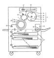
図3は、本発明の画像形成方法を実施するプロセスカートリッジおよび現像装置の一例の概略構成図であり、図3において、10は感光体ドラム1に接触して直接帯電を行う一次帯電部材である帯電ローラ、11〜13はバイアス電源、15は紙などの転写材、16は転写部材、17は定着用加圧ローラ、18は定着用加熱ローラ、19はクリーナーであり、図2と同じ部材には同じ符号を付した。
FIG. 3 is a schematic configuration diagram of an example of a process cartridge and a developing device for performing the image forming method of the present invention. In FIG. 3,
帯電ローラ10には、感光体ドラム1表面を一様に帯電するようにバイアス電源11が接続されている。現像装置7はトナー容器5内にトナー4を収容しており、矢印方向に回転するトナー担持体である現像ローラー2を具備する。さらに、トナー規制及び帯電付与のためのトナー規制部材である規制ブレード3、トナー4を現像ローラー2に付着させ、且つ現像ローラー2との摩擦でトナーへの帯電付与を行うため矢印方向に回転する塗布ローラ9も備えている。現像ローラー2には現像バイアス電源13が接続されている。塗布ローラ9にも図示しないバイアス電源が接続されており、負帯電性トナーを使用する場合は現像バイアスよりも負側に、正帯電性トナーを使用する場合は現像バイアスよりも正側に電圧が設定される。
A bias power supply 11 is connected to the charging
転写部材16には感光体ドラム1と反対極性の転写バイアス電源12が接続されている。
A transfer
トナー担持体である現像ローラー2としては、表面に弾性層を有する、いわゆる弾性ローラが好ましく用いられる。該弾性ローラに使用される弾性層の材料の硬度としては、30〜60度(asker−C/荷重1kg)のものが好適に使用される。 As the developing roller 2 which is a toner carrier, a so-called elastic roller having an elastic layer on the surface is preferably used. The hardness of the material of the elastic layer used for the elastic roller is preferably 30 to 60 degrees (asker-C / load 1 kg).
トナーコート量は規制ブレード3により制御されるが、この規制ブレード3はトナー層を介して現像ローラー2に接触している。この時の規制ブレード3と現像ローラー2との接触圧は、現像ローラー2母線方向の線圧として0.05N/cm以上0.5N/cm以下が好ましい範囲である。
The toner coat amount is controlled by a
尚、線圧とはブレード3の長さ当たりに加えられる荷重のことであり、例えば1mの当接長さを有するブレード3に1.2Nの荷重を加えて現像ローラー2に接触させた場合、線圧は1.2N/mとなる。0.05N/cmよりも小さいとトナーコート量の制御に加え均一な摩擦帯電も難しくなり、カブリの悪化等の原因となる。一方、0.5N/cmよりも大きくなるとトナー粒子が過剰な負荷を受けるため、粒子の変形や規制ブレード3或いは現像ローラー2へのトナーの融着等が発生しやすくなり、好ましくない。
Incidentally, the linear pressure is a load applied per length of the
規制ブレード3の自由端部はどのような形状でもよく、例えば断面形状が直線状のもの以外にも、先端近傍で屈曲したL字形状のものや、先端近傍が球状に膨らんだ形状のもの等が好適に用いられる。
The free end portion of the
トナー規制部材としては、基材としてステンレス、鋼、リン青銅の如き金属弾性体を用い、スリーブ当接部に当る部位に樹脂を接着あるいはコーティング塗布したものが好適に用いられる。 As the toner regulating member, a material in which a metal elastic body such as stainless steel, steel, phosphor bronze or the like is used as a base material and a resin is adhered or coated on a portion that contacts the sleeve contact portion is preferably used.
またさらに、トナー規制部材に直流電場及び/または交流電場を印加することによっても、トナーへのほぐし作用のため、均一薄層塗布性、均一帯電性がより向上し、充分な画像濃度の達成及び良質の画像を得ることができる。 Furthermore, by applying a DC electric field and / or an AC electric field to the toner regulating member, the uniform thin layer coating property and the uniform charging property are further improved due to the loosening action on the toner, and sufficient image density is achieved. A good quality image can be obtained.
図3において、矢印方向に回転する感光体ドラム1を一次帯電部材によって一様に帯電する。本例では、該一次帯電部材は、中心の芯金10bとその外周を形成した導電性弾性層10aとを基本構成とする帯電ローラ10である。該帯電ローラ10は、静電潜像担持体である感光体ドラム1の一面に抑圧力を持って当接され、感光体ドラム1の回転に伴い従動回転する。
In FIG. 3, the photosensitive drum 1 rotating in the direction of the arrow is uniformly charged by the primary charging member. In this example, the primary charging member is a charging
帯電ローラ10を用いた時の好ましいプロセス条件としては、ローラの当接圧が0.05〜5N/cmであり、印加電圧としては直流電圧或いは直流電圧に交流電圧を重畳したもの等が用いられ、特に限定されないが、直流電圧に交流電圧を重畳したものを用いた時には、交流電圧=0.5〜5dVpp、交流周波数=50Hz〜5kHz、直流電圧=±0.2〜±1.5kVであり、直流電圧を用いた時には、直流電圧=±0.2〜±5kVである。本発明においては直流電圧のみの印加電圧が好適に用いられる。
As a preferable process condition when the charging
帯電ローラ10以外の帯電手段としては、帯電ブレードを用いる方法や、導電性ブラシを用いる方法がある。これらの接触帯電手段は、非接触のコロナ帯電に比べて、高電圧が不必要になったり、オゾンの発生が低減するといった効果がある。接触帯電手段としての帯電ローラ及び帯電ブレードの材質としては、導電性ゴムが好ましく、その表面に離型性被膜を設けても良い。離型性被膜としては、ナイロン系樹脂、PVDF(ポリフッ化ビニリデン)、PVDC(ポリ塩化ビニリデン)などが適用可能である。
As charging means other than the charging
静電潜像担持体の帯電工程に次いで、例えば、発光素子からの露光14によって感光体ドラム1上に情報信号に応じた静電潜像を形成し、現像ローラー2と当接する位置においてトナーにより静電潜像を現像し可視像化する。さらに、本発明の画像形成方法において、特に感光体ドラム1上にデジタル潜像を形成した現像システムと組み合わせることで、潜像を乱さないためにドット潜像に対して忠実に現像することが可能となる。該可視像は転写部材16により転写材15に転写され、加熱ローラ18と加圧ローラ17の間を通過して定着され、永久画像を得る。尚、加熱加圧定着手段としては、ここに示したハロゲンヒーター等の発熱体を内蔵した加熱ローラ18とこれと抑圧力をもって圧接された弾性体の加圧ローラ17を基本構成とする熱ローラ方式以外に、フィルムを介してヒーターにより加熱定着する方式も用いられる。
Following the electrostatic latent image carrier charging step, for example, an electrostatic latent image corresponding to an information signal is formed on the photosensitive drum 1 by
一方、転写されずに感光体ドラム1上に残った転写残トナーは、感光体ドラム1の表面に当接されるクリーニングブレードを有するクリーナー19で回収され、感光体ドラム1はクリーニングされる。 On the other hand, the untransferred toner remaining on the photosensitive drum 1 without being transferred is collected by a cleaner 19 having a cleaning blade in contact with the surface of the photosensitive drum 1, and the photosensitive drum 1 is cleaned.
図4に、本発明の画像形成方法を中間転写体を用いて多重トナー像を記録材に一括転写する画像形成装置の一例の概略構成図を示す。 FIG. 4 shows a schematic configuration diagram of an example of an image forming apparatus that batch-transfers multiple toner images onto a recording material using an intermediate transfer member in the image forming method of the present invention.
図4において、7a〜7dはそれぞれ、ブラック、イエロー、マゼンタ、シアンの各色の現像装置、21は光源装置、22はレーザー光、23は定着装置、24は現像ユニット、25は中間転写体である中間転写ドラム、25aは導電性支持体、25bは弾性層、26はバイアス電源、27は転写材トレイ、28は二次転写装置であり、図2、図3と同じ部材には同じ符号を付した。 In FIG. 4, 7a to 7d are black, yellow, magenta, and cyan developing devices, 21 is a light source device, 22 is a laser beam, 23 is a fixing device, 24 is a developing unit, and 25 is an intermediate transfer member. An intermediate transfer drum, 25a is a conductive support, 25b is an elastic layer, 26 is a bias power source, 27 is a transfer material tray, and 28 is a secondary transfer device. The same members as those in FIGS. did.
静電潜像担持体としての感光体ドラム1の表面に、帯電部材としての帯電バイアス電圧が印加された回転可能な帯電ローラ10を回転させながら接触させて、感光体ドラム1表面を均一に一次帯電し、露光手段としての光源装置21より発せられたレーザー光22により、感光体ドラム1上に第1の静電潜像を形成する。形成された第1の静電潜像は、回転可能な現像ユニット24に設けられている第1の現像装置としてのブラック現像装置7a中のブラックトナーにより現像され、ブラックトナー像を形成する。感光体ドラム1上に形成されたブラックトナー像は、中間転写ドラム25の導電性支持体25aに印加される転写バイアス電圧の作用により、中間転写ドラム25上に静電的に一次転写される。次に、上記と同様にして感光体ドラム1の表面に第2の静電潜像を形成し、現像ユニット24を回転して、第2の現像装置としてのイエロー現像装置7b中のイエロートナーにより現像してイエロートナー像を形成し、ブラックトナー像が一次転写されている中間転写ドラム25上にイエロートナー像を静電的に一次転写する。同様にして、第3の静電潜像及び第4の静電潜像を現像ユニット24を回転して、第3の現像装置としてのマゼンタ現像装置7c中のマゼンタトナー及び第4の現像装置としてシアン現像装置7d中のシアントナーにより、順次現像及び一次転写を行って、中間転写ドラム25上に各色のトナー像をそれぞれ一次転写する。中間転写ドラム25上に一次転写された多重トナー像は、転写材15を介して反対側に位置する二次転写装置28からの転写バイアス電圧の作用により、転写材15の上に静電的に一括に二次転写される。転写材15上に二次転写された多重トナー像は加熱ローラ17及び加圧ローラ18を有する定着装置23により転写材15に加熱定着される。転写後に感光体ドラム1の表面上に残存する転写残トナーは、感光体ドラム1の表面に当接するクリーニングブレードを有するクリーナー19で回収され、感光体ドラム1はクリーニングされる。
A surface of the photosensitive drum 1 as an electrostatic latent image carrier is brought into contact with a
感光体ドラム1から中間転写ドラム25への一次転写は、一次転写装置としての中間転写ドラム25の導電性支持体25aに、バイアス電源26よりバイアスを付与することで転写電流が得られ、トナー画像の転写が行われる。
In the primary transfer from the photosensitive drum 1 to the
中間転写ドラム25は、剛体である導電性支持体25aと、表面を覆う弾性層25bよりなる。導電性支持体25aとしては、アルミニウム、鉄、銅及びステンレス等の金属や合金、及びカーボンや金属粒子等を分散した導電性樹脂等を用いることができ、その形状としては円筒状や、円筒の中心に軸を貫通したもの、円筒の内部に補強を施したもの等が挙げられる。
The
弾性層25bとしては、特に制約されるものではないが、スチレン−ブタジエンゴム、ハイスチレンゴム、ブタジエンゴム、イソプレンゴム、エチレン−プロピレン共重合体、ニトリルブタジエンゴム(NBR)、クロロプレンゴム、ブチルゴム、シリコーンゴム、フッ素ゴム、ニトリルゴム、ウレタンゴム、アクリルゴム、エピクロロヒドリンゴム及びノルボルネンゴム等のエラストマーゴムが好適に用いられる。ポリオレフィン系樹脂、シリコーン樹脂、フッ素系樹脂、ポリカーボネート等の樹脂及びこれらの共重合体や混合物を用いても良い。
The
また、弾性層25bのさらに表面に、潤滑性、撥水性の高い滑剤粉体を任意のバインダー中に分散した表面層を設けても良い。
Further, a surface layer in which lubricant powder having high lubricity and water repellency is dispersed in an arbitrary binder may be provided on the surface of the
滑剤は特に制限はないが、各種フッ素ゴム、フッ素エラストマー、黒鉛やグラファイトにフッ素を結合したフッ化炭素及びポリテトラフルオロエチレン(PTFE)、ポリフッ化ビニリデン(PVDF)、エチレン−テトラフルオロエチレン共重合体(ETFE)及びテトラフルオロエチレン−パーフルオロアルキルビニルエーテル共重合体(PFA)等のフッ素化合物、シリコーン樹脂粒子、シリコーンゴム、シリコーンエラストマー等のシリコーン系化合物、ポリエチレン(PE)、ポリプロピレン(PP)、ポリスチレン(PS)、アクリル樹脂、ポリアミド樹脂、フェノール樹脂及びエポキシ樹脂等が好ましく用いられる。 The lubricant is not particularly limited, but various fluororubbers, fluoroelastomers, fluorocarbons and polytetrafluoroethylene (PTFE), polyvinylidene fluoride (PVDF), ethylene-tetrafluoroethylene copolymers in which fluorine is bonded to graphite or graphite. (ETFE) and fluorine compounds such as tetrafluoroethylene-perfluoroalkyl vinyl ether copolymer (PFA), silicone compounds such as silicone resin particles, silicone rubber and silicone elastomer, polyethylene (PE), polypropylene (PP), polystyrene ( PS), acrylic resin, polyamide resin, phenol resin, epoxy resin and the like are preferably used.
また、表面層のバインダー中に、抵抗を制御するために導電剤を適時添加しても良い。導電剤としては、各種の導電性無機粒子及びカーボンブラック、イオン系導電剤、導電性樹脂及び導電性粒子分散樹脂等が挙げられる。 In addition, a conductive agent may be added to the surface layer binder in order to control resistance. Examples of the conductive agent include various conductive inorganic particles and carbon black, an ionic conductive agent, a conductive resin, and a conductive particle-dispersed resin.
中間転写ドラム25上の多重トナー像は、二次転写装置28により転写材15上に一括に二次転写されるが、転写装置28としてはコロナ帯電器による非接触静電転写手段或いは転写ローラ及び転写ベルトを用いた接触静電転写手段が使用可能である。
The multiple toner images on the
定着装置23としては、加熱ローラ18と加圧ローラ17を有する熱ローラ定着装置に替えて、転写材15上のトナー像に接するフィルムを加熱することにより、転写材15上のトナー像を加熱し、転写材15に多重トナー像を加熱定着するフィルム加熱定着装置を用いることもできる。
As the fixing
図4に示した画像形成装置が用いている中間転写体としての中間転写ドラム25に代えて、中間転写ベルトを用いて多重トナー像を記録材に一括転写することも可能である。中間転写ベルトを用いた装置の概略構成図を図5に示す。
Instead of the
図5において、30は中間転写ベルト、31は中間転写ベルト30を掛け渡すローラ、32は一次転写ローラ、33aは二次転写対向ローラ、33bは二次転写ローラ、34〜36はバイアス電源、39はクリーニング用帯電部材であり、図2〜図4と同じ部材には同じ符号を付した。
In FIG. 5, 30 is an intermediate transfer belt, 31 is a roller for passing the
図5の構成において、感光体ドラム1上に形成担持されたトナー画像は、感光体ドラム1と中間転写ベルト30とのニップ部を通過する過程で、一次転写ローラ32から中間転写ベルト30に印加される一次転写バイアスにより形成される電界により、中間転写ベルト30の外周面に順次一次転写される。
In the configuration of FIG. 5, the toner image formed and supported on the photosensitive drum 1 is applied from the
感光体ドラム1から中間転写ベルト30への第1〜第4色のトナー画像の順次重畳転写のための一次転写バイアスは、トナーとは逆極性で、バイアス電源34から印加される。
A primary transfer bias for sequentially superimposing and transferring the first to fourth color toner images from the photosensitive drum 1 to the
感光体ドラム1から中間転写ベルト30への第1〜第4色のトナー画像の一次転写工程において、二次転写ローラ33b及びクリーニング用帯電部材39は中間転写ベルト30から離間することも可能である。
In the primary transfer process of the first to fourth color toner images from the photosensitive drum 1 to the
33bは二次転写ローラで、二次転写対向ローラ33aに対応し平行に軸受させて中間転写ベルト30の下面部に離間可能な状態に配設してある。
中間転写ベルト30上に転写された合成カラートナー画像の転写材15への転写は、二次転写ローラ33bが中間転写ベルト30に当接されると共に、中間転写ベルト30と二次転写ローラ33bとの当接ニップに所定のタイミングで転写材15が給送され、二次転写バイアスがバイアス電源36から二次転写ローラ33bに印加される。この二次転写バイアスにより中間転写ベルト30から転写材15へ合成カラートナー画像が二次転写される。
When the composite color toner image transferred onto the
転写材15への画像転写終了後、中間転写ベルト30にはクリーニング用帯電部材39が当接され、感光体ドラム1とは逆極性のバイアスをバイアス電源35から印加することにより、転写材15に転写されずに中間転写ベルト30上に残留しているトナー(転写残トナー)に感光体ドラム1と逆極性の電荷が付与される。次いで、該転写残トナーは、感光体ドラム1とのニップ部及びその近傍において感光体ドラム1に転写されることにより、中間転写ベルト30がクリーニングされる。
After the image transfer to the
中間転写ベルト30は、ベルト形状の基層と基層の上に設けられる表面処理層よりなる。尚、表面処理層は複数の層により構成されていても良い。
The
基層及び表面処理層には、ゴム、エラストマー、樹脂を使用することができる。例えばゴム、エラストマーとしては、天然ゴム、イソプレンゴム、スチレン−ブタジエンゴム、ブタジエンゴム、ブチルゴム、エチレン−プロピレンゴム、エチレン−プロピレンターポリマー、クロロプレンゴム、クロロスルホン化ポリエチレン、塩素化ポリエチレン、アクリロニトリルブタジエンゴム、ウレタンゴム、シンジオタクチック1,2−ポリブタジエン、エピクロロヒドリンゴム、アクリルゴム、シリコーンゴム、フッ素ゴム、多硫化ゴム、ポリノルボルネンゴム、水素化ニトリルゴム及び熱可塑性エラストマー(例えばポリスチレン系、ポリオレフィン系、ポリ塩化ビニル系、ポリウレタン系、ポリアミド系、ポリエステル系及びフッ素樹脂系等)等からなる群より選ばれる1種類或いは2種類以上を使用することができる。但し、上記材料に限定されるものではない。また、樹脂としては、ポリオレフィン系樹脂、シリコーン樹脂、フッ素系樹脂、ポリカーボネート等の樹脂を使用することができる。これら樹脂の共重合体や混合物を用いても良い。 Rubber, elastomer, or resin can be used for the base layer and the surface treatment layer. For example, as rubber and elastomer, natural rubber, isoprene rubber, styrene-butadiene rubber, butadiene rubber, butyl rubber, ethylene-propylene rubber, ethylene-propylene terpolymer, chloroprene rubber, chlorosulfonated polyethylene, chlorinated polyethylene, acrylonitrile butadiene rubber, Urethane rubber, syndiotactic 1,2-polybutadiene, epichlorohydrin rubber, acrylic rubber, silicone rubber, fluorine rubber, polysulfurized rubber, polynorbornene rubber, hydrogenated nitrile rubber and thermoplastic elastomer (for example, polystyrene, polyolefin, One type or two or more types selected from the group consisting of polyvinyl chloride, polyurethane, polyamide, polyester, fluororesin, and the like can be used. However, it is not limited to the above materials. As the resin, a resin such as a polyolefin resin, a silicone resin, a fluorine resin, or a polycarbonate can be used. A copolymer or a mixture of these resins may be used.
基層としては上述のゴム、エラストマー、樹脂をフィルム状にして使用することができる。また、これらの物質を、織布形状、不織布形状、糸状、フィルム形状をした芯体層の片面或いは両面に上述のゴム、エラストマー、樹脂を被覆、浸漬、噴霧したものを使用しても良い。 As the base layer, the rubber, elastomer and resin described above can be used in the form of a film. In addition, a material obtained by coating, dipping, or spraying the above-described rubber, elastomer, or resin on one side or both sides of a core layer in the form of a woven fabric, a nonwoven fabric, a thread, or a film may be used.
芯体層を構成する材料は、例えば綿、絹、麻及び羊毛等の不然繊維;キチン繊維、アルギン酸繊維維及び再生セルロース繊維等の再生織維;アセテート繊維等の半合成繊維;ポリエステル繊維、ナイロン繊維、アクリル繊維、ポリオレフィン繊維、ポリビニルアルコール繊維、ポリ塩化ビニル繊維、ポリ塩化ビニリデン繊維、ポリウレタン繊維、ポリアルキルパラオキシベンゾエート繊維、ポリアセタール繊維、アラミド繊維、ポリフロロエチレン繊維及びフェノール繊維等の合成繊維;炭素繊維、硝子繊維及びボロン繊維等の無機繊維;鉄繊維及び銅繊維等の金属繊維からなる群より選ばれる1種或いは2種以上を用いることができる。もちろん、上記材料に限定されるものではない。 Materials constituting the core layer are, for example, natural fibers such as cotton, silk, hemp and wool; regenerated woven fibers such as chitin fiber, alginate fiber and regenerated cellulose fiber; semisynthetic fibers such as acetate fiber; polyester fiber, nylon Synthetic fibers such as fiber, acrylic fiber, polyolefin fiber, polyvinyl alcohol fiber, polyvinyl chloride fiber, polyvinylidene chloride fiber, polyurethane fiber, polyalkyl paraoxybenzoate fiber, polyacetal fiber, aramid fiber, polyfluoroethylene fiber and phenol fiber; carbon One or more selected from the group consisting of inorganic fibers such as fibers, glass fibers and boron fibers; metal fibers such as iron fibers and copper fibers can be used. Of course, the material is not limited to the above.
さらに、中間転写ベルト30の低抗値を調節するために基層及び表面処理層中に導電剤を添加しても良い。導電剤としては特に限定されるものではないが、例えば、カーボン、アルミニウムやニッケル等の金属粉末、酸化チタン等の金属酸化物、及び4級アンモニウム塩含有ポリメタクリル酸メチル、ポリビニルアニリン、ポリビニルピロール、ポリジアセチレン、ポリエチレンイミン、含ホウ素高分子化合物及びポリピロール等の導電性高分子化合物等からなる群より選ばれる1種或いは2種以上を用いることができる。但し、上記導電剤に限定されるものではない。
Further, a conductive agent may be added to the base layer and the surface treatment layer in order to adjust the resistance value of the
また、中間転写ベルト30表面の滑り性を上げ、転写性を向上するために必要に応じて滑剤を添加しても良い。該滑剤としては特に制限はないが、各種フッ素ゴム、フッ素エラストマー、黒鉛やグラファイトにフッ素を結合したフッ化炭素及びポリテトラフルオロエチレン(PTFE)、ポリフッ化ビニルデン(PVDF)、エチレン−テトラフルオロエチレン共重合体(ETFE)及びテトラフルオロエチレン−パーフルオロアルキルビニルエーテル共重合体(PFA)等のフッ素化合物、シリコーン樹脂、シリコーンゴム、シリコーンエラストマー等のシリコーン系化合物、ポリエチレン(PE)、ポリプロピレン(PP)、ポリスチレン(PS)、アクリル樹脂、ポリアミド樹脂、フェノール樹脂及びエポキシ樹脂等が好ましく用いられる。
Further, a lubricant may be added as necessary to increase the slipperiness of the surface of the
次に、複数画像形成部にて各色のトナー画像をそれぞれ形成し、これを同一転写材に順次重ねて転写するようにした装置の概略構成図を図6をもとに説明する。 Next, a schematic configuration diagram of an apparatus in which toner images of respective colors are respectively formed by a plurality of image forming units and transferred sequentially on the same transfer material will be described with reference to FIG.
図6において、1a〜1dは感光体ドラム、19a〜19dはクリーナー、41a〜41dは画像形成部、42a〜42dは潜像形成手段、43a〜43dは転写用放電部、44a〜44dは一次帯電部、45は除電器、46は搬送ベルト、7a〜7dは現像装置、48は吸着帯電器、49a〜49dは分離除電放電部、50は排出口であり、図2〜図4と同じ部材には同じ符号を付した。 In FIG. 6, 1a to 1d are photosensitive drums, 19a to 19d are cleaners, 41a to 41d are image forming units, 42a to 42d are latent image forming means, 43a to 43d are transfer discharge units, and 44a to 44d are primary charges. , 45 is a static eliminator, 46 is a conveyor belt, 7a to 7d are developing devices, 48 is an adsorption charger, 49a to 49d are separation and neutralization discharge units, and 50 is a discharge port. Have the same symbols.
図6の構成では、第1〜第4の画像形成部41a〜41dが並設されており、各画像形成部はそれぞれ専用の静電潜像担持体である感光体ドラム1a〜1dを具備している。感光体ドラム1a〜1dはその外周側に潜像形成手段42a〜42d、現像装置7a〜7d、転写用放電部43a〜43d、クリーナー19a〜19d、一次帯電部44a〜44dが配置されている。
In the configuration of FIG. 6, first to fourth image forming units 41 a to 41 d are arranged in parallel, and each image forming unit includes photosensitive drums 1 a to 1 d which are dedicated electrostatic latent image carriers. ing. Latent image forming means 42a to 42d, developing devices 7a to 7d,
このような構成にて、先ず、第1画像形成部41aの感光体ドラム1a上に潜像形成手段42aによって原稿画像における、例えばイエロー成分色の潜像が形成される。該潜像は現像装置7aのイエロートナーで可視画像とされ、転写用放電部43aにて転写材15に転写される。
With such a configuration, first, for example, a yellow component color latent image in the original image is formed on the photosensitive drum 1a of the first image forming unit 41a by the latent image forming unit 42a. The latent image is made a visible image with yellow toner of the developing device 7a, and is transferred to the
上記のようにイエロー画像が転写材15に転写されている間に、第2画像形成部41bではマゼンタ成分色の潜像が感光体ドラム1b上に形成され、続いて現像装置7bのマゼンタトナーで可視画像とされる。この可視画像(マゼンタトナー像)は、上記の第1画像形成部41aでの転写が終了した転写材15が転写用放電部42bに搬入された時に、該転写材15の所定位置に重ねて転写される。
As described above, while the yellow image is transferred to the
以下、上記と同様な方法により第3、第4の画像形成部41c、41dにおいて、シアン色、ブラック色の画像形成が行なわれ、上記同一の転写材15に、シアン色、ブラック色を重ねて転写するのである。このような画像形成プロセスが終了したならば、転写材15は定着装置23に搬送され、転写材15上の画像を定着する。これによって転写材15上には多色画像が得られるのである。転写が終了した各感光体ドラム1a〜1dはクリーナー19a〜19dにより残留トナーを除去され、引き続き行なわれる次の潜像形成のために供せられる。
Thereafter, cyan and black images are formed in the third and fourth
尚、上記画像形成装置では、転写材15の搬送のために、搬送ベルト46が用いられており、図6において、転写材5は右側から左側へ搬送され、その搬送過程で、各画像形成部41a〜41dにおける各転写用放電部43a〜43dを通過し、転写を受ける。
In the image forming apparatus, a
この画像形成方法をおいて、転写材15を搬送する搬送手段として加工の容易性及び耐久性の観点からテトロン繊維のメッシュを用いた搬送ベルト及びポリエチレンテレフタレート系樹脂、ポリイミド系樹脂、ウレタン系樹脂の如き薄い誘電体シートを用いた搬送ベルトが利用される。
In this image forming method, from the viewpoint of ease of processing and durability as a transport means for transporting the
転写材15が第4画像形成部41dを通過すると、直流電圧が除電器45に加えられ、転写材15は除電され、搬送ベルト46から分離され、その後、定着装置23に入り、画像定着され、排出口50から排出される。
When the
尚、この装置では、複数の画像形成部にそれぞれ独立した静電潜像担持体を具備しており、転写材はベルト式の搬送手段で、順次、各静電潜像担持体の転写部へ送られるように構成されているが、上記画像形成部に共通する静電潜像担持体を具備し、転写材がドラム式の搬送手段で、上記静電潜像担持体の転写部へ繰返し送られて、各色の転写を受けるように構成してもよい。 In this apparatus, each of the plurality of image forming units includes an independent electrostatic latent image carrier, and the transfer material is sequentially transferred to the transfer unit of each electrostatic latent image carrier by a belt-type conveying unit. The electrostatic latent image carrier that is common to the image forming unit is provided, and the transfer material is repeatedly sent to the transfer unit of the electrostatic latent image carrier by a drum-type conveyance unit. It may be configured to receive the transfer of each color.
図6の搬送ベルト方式では、体積抵抗が高いため、カラー画像形成装置におけるように、数回の転写を繰り返す過程で、搬送ベルトが帯電量を増加させて行く。このため、各転写の都度、転写電流を順次増加させないと、均一な転写を維持できないが、本発明のトナーは転写性が優れているので、転写を繰り返す毎に搬送ベルトの帯電が増しても、同じ転写電流で各転写におけるトナーの転写性を均一化でき、良質な高品位画像が得られることになる。 In the conveyance belt system of FIG. 6, since the volume resistance is high, the conveyance belt increases the charge amount in the process of repeating the transfer several times as in the color image forming apparatus. For this reason, uniform transfer cannot be maintained unless the transfer current is sequentially increased for each transfer. However, since the toner of the present invention has excellent transferability, the charge of the conveyor belt increases every time the transfer is repeated. Thus, the transferability of toner in each transfer can be made uniform with the same transfer current, and a high-quality high-quality image can be obtained.
さらに図7に本発明の画像形成方法を実施する他の装置例の概略構成図を示し、以下に説明する。 Further, FIG. 7 shows a schematic configuration diagram of another example of an apparatus for carrying out the image forming method of the present invention, which will be described below.
図7において、44は一次帯電部、60は転写ドラム、61はグリッパー、62は転写帯電器、63a、63bは分離帯電器、64は分離ガイドであり、図2〜図6と同じ部材には同じ符号を付した。 In FIG. 7, 44 is a primary charging unit, 60 is a transfer drum, 61 is a gripper, 62 is a transfer charger, 63a and 63b are separation chargers, and 64 is a separation guide. The same symbols are attached.
図7の構成において、感光体ドラム1上に適当な手段で形成された静電潜像は、矢印の方向へ回転する現像ユニット24に取り付けられた現像装置7a〜7d中の第1の現像装置7aにおいて、トナーにより可視化される。感光体ドラム1上のカラートナー画像は、グリッパー61によって転写ドラム60上に保持されている転写材15に、転写帯電器62により転写される。転写後に感光体ドラム1の表面上に残存する転写残トナーは、感光体ドラム1の表面に当接するクリーニングブレードを有するクリーナー19で回収され、感光体ドラム1はクリーニングされる。
In the configuration of FIG. 7, the electrostatic latent image formed on the photosensitive drum 1 by a suitable means is a first developing device among the developing devices 7a to 7d attached to the developing
転写帯電器62には、コロナ帯電器または接触帯電器が利用され、転写帯電器62にコロナ帯電器が使われる場合には、−10kV〜+10kVの電圧が印加され、転写電流は−500μA〜+500μAである。転写ドラム60の外周面には保持部材が張設され、この保持部材はポリフッ化ビニリデン樹脂フィルムやポリエチレンテレフタレートの如きフィルム状誘電体シートによって構成される。例えば、厚さ100μm〜200μm、体積抵抗1012〜1014Ω・cmのシートが用いられる。
As the
次に2色目として現像ユニット24が回転し、現像装置7bが感光体ドラム1に対向する。そして現像装置7bにおいて第2のトナーにより現像され、このトナー画像も前記と同一の転写材15上に重ねて転写される。
Next, the developing
さらに3色目、4色目も同様に行なわれる。このように転写ドラム60は転写材15を担持したまま所定回数だけ回転し、所定色数のトナー像が多重転写される。静電転写するための転写電流は、1色目<2色目<3色目<4色目の順に高めることが感光体ドラム1上に残る転写残留トナーを少なくするために好ましい。
Further, the third color and the fourth color are similarly performed. In this way, the
多重転写された転写材15は、分離帯電器63a、63bにより転写ドラム60より分離され、加熱加圧ローラ定着装置23で定着され、定着時に加色混合されることにより、フルカラー複写画像となる。
The
図8に、本発明の画像形成方法を実施する他の装置例として、中間転写ドラム上に一次転写された4色のカラートナー画像を転写材に一括して二次転写する際の二次転写手段として、転写ベルトを用いた画像形成装置の概略構成図を示す。 FIG. 8 shows another example of the apparatus for carrying out the image forming method of the present invention. Secondary transfer when four color toner images primarily transferred onto the intermediate transfer drum are collectively transferred onto a transfer material. As a means, a schematic configuration diagram of an image forming apparatus using a transfer belt is shown.
図8に示す装置において、現像装置7a〜7dに、それぞれブラック、イエロー、シアン、マゼンタの各色のトナーが導入され、感光体ドラム1に形成された静電潜像を現像し、各色トナー像が感光体ドラム1上に形成される。感光体ドラム1はa−Se、Cds、ZnO2、OPC、a−Siの様な光導電絶縁物質層71bを持ち、図示しない駆動装置によって矢印方向に回転される。感光層71aには、アモルファスシリコン感光層、または有機感光層を有する感光体が好ましく用いられる。
In the apparatus shown in FIG. 8, toners of respective colors of black, yellow, cyan, and magenta are introduced into the developing devices 7a to 7d, respectively, and the electrostatic latent image formed on the photosensitive drum 1 is developed. It is formed on the photosensitive drum 1. The photosensitive drum 1 has a photoconductive insulating
有機感光層としては、感光層が電荷発生物質及び電荷輸送性能を有する物質を同一層に含有する、単一層型でもよく、または、電荷輸送層を電荷発生層を成分とする機能分離型感光層であっても良い。導電性基体上に電荷発生層、次いで電荷輸送層の順で積層されている構造の積層型感光層は好ましい例の一つである。 The organic photosensitive layer may be a single layer type in which the photosensitive layer contains a charge generation substance and a substance having charge transport performance in the same layer, or a function-separated type photosensitive layer having the charge generation layer as a component. It may be. A laminated photosensitive layer having a structure in which a charge generation layer and then a charge transport layer are laminated in this order on a conductive substrate is one preferred example.
有機感光層の結着樹脂はポリカーボネート樹脂、ポリエステル樹脂、アクリル系樹脂が特に、転写性、クリーニング性が良く、クリーニング不良、感光体へのトナーの融着、外添剤のフィルミングが起こりにくい。 The binder resin for the organic photosensitive layer is particularly a polycarbonate resin, a polyester resin, or an acrylic resin, and has good transferability and cleaning properties, and poor cleaning, toner fusion to the photoreceptor, and filming of external additives are unlikely to occur.
帯電工程では、コロナ帯電器を用いる感光体ドラム1とは非接触である方式と、ローラ等を用いる接触型の方式がありいずれのものも用いられるが、効率的な均一帯電、シンプル化、低オゾン発生化のために図8に示す如く接触方式のものが好ましく用いられる。 In the charging process, there are a non-contact method with the photosensitive drum 1 using a corona charger and a contact type method using a roller or the like, and either one is used, but efficient uniform charging, simplification, low In order to generate ozone, a contact type as shown in FIG. 8 is preferably used.
帯電ローラ10は、中心の芯金10bとその外周を形成した導電性弾性層10aとを基本構成とするものである。帯電ローラ10は、感光体ドラム1面に押圧力をもって圧接され、感光体ドラム1の回転に伴い従動回転する。
The charging
帯電ローラ10を用いた時の好ましいプロセス条件としては、図3の装置と同様である。
Preferred process conditions when using the charging
感光体ドラム1上のトナー像は、電圧(例えば、±0.1〜±5kV)が印加されている中間転写ドラム25に転写される。転写後の感光体ドラム1表面は、クリーニングブレードを有するクリーナー19でクリーニングされる。
The toner image on the photosensitive drum 1 is transferred to the
中間転写ドラム25は感光体ドラム1に対して並行に軸受けさせて感光体ドラム1の下面部に接触させて配設してあり、感光体ドラム1と同じ周速度で矢印の反時計方向に回転する。
The
感光体ドラム1の面に形成担持された第1色のトナー像が、感光体ドラム1と中間転写ドラム25とが接する転写ニップ部を通過する過程で中間転写ドラム25に対する印加転写バイアスで転写ニップ域に形成された電界によって、中間転写ドラム25の外面に対して順次に中間転写されていく。
The first color toner image formed and supported on the surface of the photosensitive drum 1 passes through the transfer nip where the photosensitive drum 1 and the
必要により、着脱自在なクリーニング手段72により、転写材15へのトナー像の転写後に、中間転写ドラム25の表面がクリーニングされる。中間転写ドラム25上にトナー像がある場合、トナー像を乱さないようにクリーニング手段72は、中間転写ドラム25表面から離される。
If necessary, the surface of the
中間転写ドラム25に対して並行に軸受けさせて中間転写ドラム25の下面部に接触させて転写手段が配設される。転写手段は例えば転写ローラまたは転写ベルトであり、中間転写ドラム25と同じ周速度で矢印の時計方向に回転する。転写手段73は直接中間転写ドラム25と接触するように配設されていても良く、またベルト等が中間転写ドラム25と転写手段との間に接触するように配置されても良い。
The transfer means is disposed by bearing in parallel with the
転写手段が転写ローラの場合、中心の芯金とその外周を形成した導電性弾性層とを基本構成とするものである。 When the transfer means is a transfer roller, the transfer roller is basically composed of a central cored bar and a conductive elastic layer forming the outer periphery thereof.
中間転写ドラム及び転写ローラとしては、一般的な材料を用いることが可能である。中間転写ドラム25の弾性層25bの体積固有抵抗値よりも転写ローラの弾性層の体積固有低抗値をより小さく設定することで転写ローラへの印加電圧が軽減でき、転写材15上に良好なトナー像を形成できると共に転写材15の中間転写ドラム25への巻き付きを防止することができる。特に中間転写ドラム25の弾性層25bの体積固有低抗値が転写ローラの弾性層の体積固有抵抗値より10倍以上であることが特に好ましい。
Common materials can be used for the intermediate transfer drum and the transfer roller. By setting the volume specific resistance value of the elastic layer of the transfer roller to be smaller than the volume specific resistance value of the
中間転写ドラム及び転写ローラの硬度は、JIS K−6301に準拠し測定される。本発明に用いられる中間転写ドラム25は、10〜40度の範囲に属する弾性層25bから構成されることが好ましく、一方、転写ローラの弾性層の硬度は、中間転写ドラム25の弾性層25bの硬度より硬く41〜80度の値を有するものが中間転写ドラム25ヘの転写材15の巻き付きを防止する上で好ましい。中間転写ドラム25と転写ローラの硬度が逆になると、転写ローラ側に凹部が形成され、中間転写ドラム25ヘの転写材15の巻き付きが発生しやすい。
The hardness of the intermediate transfer drum and the transfer roller is measured according to JIS K-6301. The
図8では中間転写ドラム25の下方には、転写ベルト73が配置されている。転写ベルト73は、中間転写ドラム25の軸に対して並行に配置された2本のローラ、即ちバイアスローラ74とテンションローラ75に掛け渡されており、駆動手段(不図示)によって駆動される。転写ベルト73は、テンションローラ75側を中心にしてバイアスローラ74側が矢印方向に移動可能に構成されていることにより、中間転写ドラム25に対して下方から矢印方向に接離することができる。バイアスローラ74には、二次転写用のバイアス電源76によって所望の二次転写バイアスが印加されており、一方、テンションローラ75は接地されている。
In FIG. 8, a
次に、転写ベルト73としては、例えば、熱硬化性ウレタンエラストマーにカーボンを分散させ厚さ約300μm、体積抵抗率108〜1012Ω・cm(1kV印加時)に制御した上に、フッ素ゴム20μm、体積抵抗率1015Ω・cm(1kV印加時)に制御したゴムベルトが用いられる。その外径寸法は周長80×幅300mmのチューブ形状である。
Next, as the
上述の転写ベルト73は、前述のバイアスローラ74とテンションローラ75によって約5%延ばす張力印加がなされている。
The
転写ベルト73は中間転写ドラム25と等速度或は周速度に差をつけて回転させる。転写材15は中間転写ドラム25と転写ベルト73との間に搬送されると同時に、転写ベルト73にトナーが有する摩擦電荷と逆極性のバイアスをバイアス電源76から印加することによって、中間転写ドラム25上のトナー像が転写材15の表面側に転写される。
The
転写用回転体の材質としては、帯電ローラと同様のものも用いることができ、好ましい転写のプロセス条件としては、ローラの当接圧が5〜500g/cmで、直流電圧が±0.2〜±10kVである。 The material for the transfer rotator can be the same as that of the charging roller. Preferred transfer process conditions include a roller contact pressure of 5 to 500 g / cm and a DC voltage of ± 0.2 to ± 10 kV.
例えば、バイアスローラ74の導電性弾性層74bはカーボン等の導電材を分散させたポリウレタン、エチレン−プロピレン−ジエン系三元共重合体(EPDM)等の体積抵抗106〜1010Ωcm程度の弾性体で作られている。芯金74aには定電圧バイアス電源によりバイアスが印加されている。バイアス条件としては、±0.2〜±10kVが好ましい。
For example, the conductive elastic layer 74b of the
次いで転写材15は、ハロゲンヒータ等の発熱体を内蔵させた加熱ローラ18とこれと押圧力をもって圧接された弾性体の加圧ローラ17とを基本構成とする定着装置23へ搬送され、加熱ローラ18と加圧ローラ17間を通過することによってトナー像が転写材15に加熱加圧定着される。フィルムを介してヒータにより定着する方法を用いても良い。
Subsequently, the
以下に実施例及び比較例を挙げて本発明を具体的に説明する。なお、以下の実施例等における「部」は「質量部」である。 The present invention will be specifically described below with reference to examples and comparative examples. In addition, “parts” in the following examples and the like are “parts by mass”.
(離型剤微粒子分散液1の調製)
脱塩水78.33部、ベヘン酸ベヘニルを主体とするエステル化合物(ユニスターM−2222SL、日本油脂製)20部、ドデシルベンゼンスルホン酸ナトリウム1.7部を混合し、90℃にて高圧剪断をかけ乳化し、離型剤微粒子分散液1を得た。平均粒径は340nmであった。
(Preparation of release agent fine particle dispersion 1)
78.33 parts of demineralized water, 20 parts of an ester compound mainly composed of behenyl behenate (Unistar M-2222SL, manufactured by NOF Corporation) and 1.7 parts of sodium dodecylbenzenesulfonate were mixed and subjected to high-pressure shearing at 90 ° C. Emulsification was performed to obtain a release agent fine particle dispersion 1. The average particle size was 340 nm.
(離型剤微粒子分散液2の調製)
エステル化合物をステアリン酸ステアリルを主体とするエステル化合物(ユニスターM9676、日本油脂製)20部に変更する以外には、離型剤微粒子分散液1と同様の方法にて分散液2を得た。平均粒径は350nmであった。
(Preparation of release agent fine particle dispersion 2)
Dispersion 2 was obtained in the same manner as release agent fine particle dispersion 1, except that the ester compound was changed to 20 parts of an ester compound mainly composed of stearyl stearate (Unistar M9766, manufactured by NOF Corporation). The average particle size was 350 nm.
(離型剤微粒子分散液3の調製)
エステル化合物をポリプロピレンワックスに変更すること以外には、離型剤微粒子分散液1と同様の方法にて分散液2を得た。平均粒径は420nmであった。
(Preparation of release agent fine particle dispersion 3)
Dispersion 2 was obtained in the same manner as release agent fine particle dispersion 1, except that the ester compound was changed to polypropylene wax. The average particle size was 420 nm.
(樹脂微粒子分散液1の調製)
・スチレン 71質量部
・nブチルアクリレート 29質量部
・アクリル酸 3質量部
・ジビニルベンゼン 0.95質量部
・オクタンチオール 0.35質量部
・四臭化炭素 0.7質量部
以上を混合し、溶解したものを、非イオン性界面活性剤(三洋化成(株)製:ノニポール400)1.5質量部及びアニオン性界面活性剤(第一工業製薬(株)製:ネオゲンSC)3.5質量部をイオン交換水150質量部に溶解したものに、フラスコ中で分散し、乳化し、ゆっくりと混合しながら、これに過硫酸アンモニウム3.2質量部を溶解したイオン交換水10質量部を10分間かけて滴下した。10分後、速やかに内容物を反応容器(容積1リットルのオートクレーブ、攪拌子内在)に投入し、圧縮窒素を用いて反応容器内の圧力を230kPa(N/m2)になるよう調製した。その後、内容物を撹拌しながら内容物が65℃になるまでオイルバスで加熱し、1時間後さらに70℃に昇温して4時間乳化重合を継続した。この間、230±20kPaの範囲に収まるよう圧縮窒素の圧力弁を適宜調整した。所定時間後、反応容器内の圧力を通常大気圧(約100kPa)に戻し、内容物を取り出した。こうして、平均粒径が0.08μmである樹脂粒子を分散させてなる樹脂粒子分散液1を調製した。
(Preparation of resin fine particle dispersion 1)
-71 parts by mass of styrene-29 parts by mass of n-butyl acrylate-3 parts by mass of acrylic acid-0.95 parts by mass of divinylbenzene-0.35 parts by mass of octanethiol-0.7 parts by mass of carbon tetrabromide The non-ionic surfactant (Sanyo Kasei Co., Ltd .: Nonipol 400) 1.5 parts by mass and the anionic surfactant (Daiichi Kogyo Seiyaku Co., Ltd .: Neogen SC) 3.5 parts by mass. Is dissolved in 150 parts by mass of ion-exchanged water, dispersed in a flask, emulsified, and slowly mixed with 10 parts by mass of ion-exchanged water having 3.2 parts by mass of ammonium persulfate dissolved therein over 10 minutes. And dripped. Ten minutes later, the contents were immediately charged into a reaction vessel (autoclave having a volume of 1 liter, with a stirrer), and the pressure in the reaction vessel was adjusted to 230 kPa (N / m 2 ) using compressed nitrogen. Thereafter, the contents were heated with an oil bath until the contents reached 65 ° C. while stirring the contents. After 1 hour, the temperature was further raised to 70 ° C. and emulsion polymerization was continued for 4 hours. During this time, the pressure valve for compressed nitrogen was appropriately adjusted so as to be within the range of 230 ± 20 kPa. After a predetermined time, the pressure in the reaction vessel was returned to normal atmospheric pressure (about 100 kPa), and the contents were taken out. Thus, a resin particle dispersion 1 in which resin particles having an average particle diameter of 0.08 μm were dispersed was prepared.
(樹脂微粒子分散液2の調製)
・スチレン 75質量部
・nブチルアクリレート 23質量部
・アクリル酸 2質量部
・ジビニルベンゼン 1.15質量部
・四臭化炭素 0.7質量部
・2−メチルカプトエタノール 3.0質量部
以上を混合し、溶解したものを、非イオン性界面活性剤1.5質量部及びアニオン性界面活性剤2.2質量部をイオン交換水150質量部に溶解したものに、フラスコ中で分散し、乳化し、ゆっくりと混合しながら、これに過硫酸アンモニウム1.0質量部を溶解したイオン交換水10質量部を10分間かけて滴下した。10分後、速やかに内容物を反応容器(容積1リットルのオートクレーブ、攪拌子内在)に投入し、圧縮窒素を用いて反応容器内の圧力を230kPa(N/m2)になるよう調製した。その後、内容物を撹拌しながら内容物が90℃になるまでオイルバスで加熱し、1時間後さらに95℃に昇温して4時間乳化重合を継続した。この間、230±20kPaの範囲に収まるよう圧縮窒素の圧力弁を適宜調整した。所定時間後、反応容器内の圧力を通常大気圧(約100kPa)に戻し、平均粒径が0.29μmである樹脂微粒子を分散させてなる樹脂微粒子分散液2を調製した。
(Preparation of resin fine particle dispersion 2)
・ 75 parts by mass of
(樹脂微粒子分散液3の調製)
・スチレン 70質量部
・メチルメタアクリレート 5質量部
・nブチルアクリレート 25質量部
・アクリル酸 2質量部
・ジビニルベンゼン 1.1質量部
・四臭化炭素 0.7質量部
以上を混合し、溶解したものを、非イオン性界面活性剤1.5質量部及びアニオン性界面活性剤1.5質量部をイオン交換水150質量部に溶解したものに、フラスコ中で分散し、乳化し、ゆっくりと混合しながら、これに過硫酸アンモニウム1.8質量部および過硫酸カリウム1.2質量部を溶解したイオン交換水10質量部を10分間かけて滴下した。10分後、速やかに内容物を反応容器(容積1リットルのオートクレーブ、攪拌子内在)に投入し、圧縮窒素を用いて反応容器内の圧力を230kPa(N/m2)になるよう調製した。その後、内容物を撹拌しながら内容物が70℃になるよう1時間加熱した後、65℃で4時間乳化重合を継続した。この間、230±20kPaの範囲に収まるよう圧縮窒素の圧力弁を適宜調整した。所定時間後、反応容器内の圧力を通常大気圧(約100kPa)に戻し、平均粒径が0.50μmである樹脂粒子を分散させてなる樹脂微粒子分散液3を調製した。
(Preparation of resin fine particle dispersion 3)
-
(樹脂粒子分散液4の調製)
・スチレン 70質量部
・nブチルアクリレート 30質量部
・アクリル酸 2質量部
・ジビニルベンゼン 1.31質量部
・ドデシルメルカプタン 1.5質量部
・四臭化炭素 3.5質量部
以上を混合し、溶解したものを、非イオン性界面活性剤1.5質量部及びアニオン性界面活性剤1.0質量部をイオン交換水150質量部に溶解したものに、フラスコ中で分散し、乳化し、ゆっくりと混合しながら、これに過硫酸アンモニウム4.0質量部を溶解したイオン交換水10質量部を10分間かけて滴下した。10分後、速やかに内容物を反応容器(容積1リットルのオートクレーブ、攪拌子内在)に投入し、圧縮窒素を用いて反応容器内の圧力を230kPa(N/m2)になるよう調製した。その後、内容物を撹拌しながら内容物が80℃になるまでオイルバスで加熱し、0.5時間乳化重合を継続した。この間、230±20kPaの範囲に収まるよう圧縮窒素の圧力弁を適宜調整した。反応容器内の圧力を通常大気圧(約100kPa)に戻したのち、氷水を用いて5℃に急冷することで、平均粒径が0.77μmである樹脂微粒子を分散させてなる樹脂粒子分散液4を調製した。
(Preparation of resin particle dispersion 4)
-70 parts by weight of styrene-30 parts by weight of n-butyl acrylate-2 parts by weight of acrylic acid-1.31 parts by weight of divinylbenzene-1.5 parts by weight of dodecyl mercaptan-3.5 parts by weight of carbon tetrabromide In a flask, 1.5 parts by weight of a nonionic surfactant and 1.0 part by weight of an anionic surfactant dissolved in 150 parts by weight of ion-exchanged water are dispersed, emulsified, and slowly. While mixing, 10 parts by mass of ion-exchanged water in which 4.0 parts by mass of ammonium persulfate was dissolved was dropped over 10 minutes. Ten minutes later, the contents were immediately charged into a reaction vessel (autoclave having a volume of 1 liter, with a stirrer), and the pressure in the reaction vessel was adjusted to 230 kPa (N / m 2 ) using compressed nitrogen. Thereafter, while stirring the contents, the contents were heated in an oil bath until the contents reached 80 ° C., and emulsion polymerization was continued for 0.5 hours. During this time, the pressure valve for compressed nitrogen was appropriately adjusted so as to be within the range of 230 ± 20 kPa. Resin particle dispersion liquid in which resin fine particles having an average particle diameter of 0.77 μm are dispersed by returning the pressure in the reaction vessel to normal atmospheric pressure (about 100 kPa) and then rapidly cooling to 5 ° C. using ice water. 4 was prepared.
(樹脂微粒子分散液5の調製)
・スチレン 73質量部
・nブチルアクリレート 22質量部
・ジビニルベンゼン 2.25質量部
・アクリル酸 4質量部
・ヘキサンジオールジアクリレート 3質量部
・四臭化炭素 1.7質量部
以上を混合し、溶解したものを、非イオン性界面活性剤1.5質量部及びアニオン性界面活性剤2.2質量部をイオン交換水150質量部に溶解したものに、フラスコ中で分散し、乳化し、ゆっくりと混合しながら、これに過硫酸アンモニウム2.5質量部および過酸化水素0.5質量部を溶解したイオン交換水10質量部を10分間かけて滴下した。10分後、速やかに内容物を反応容器(容積1リットルのオートクレーブ、攪拌子内在)に投入し、圧縮窒素を用いて反応容器内の圧力を230kPa(N/m2)になるよう調製した。その後、内容物を撹拌しながら内容物が105℃になるまでオイルバスで加熱し、2時間後110℃に昇温して乳化重合を継続した。この間、230±20kPaの範囲に収まるよう圧縮窒素の圧力弁を適宜調整した。所定時間後、反応容器内の圧力を通常大気圧(約100kPa)に戻し、平均粒径が0.28μmである樹脂微粒子を分散させてなる樹脂微粒子分散液5を調製した。
(Preparation of resin fine particle dispersion 5)
-
(樹脂微粒子分散液6の調製)
・スチレン 80質量部
・nブチルアクリレート 20質量部
・アクリル酸 3質量部
・ジビニルベンゼン 1.45質量部
以上を混合し、溶解したものを、非イオン性界面活性剤1.5質量部及びアニオン性界面活性剤2.2質量部をイオン交換水150質量部に溶解したものに、フラスコ中で分散し、乳化し、10分間ゆっくりと混合しながら、これに過硫酸アンモニウム1.7質量部を溶解したイオン交換水10質量部を投入し、窒素置換を行った後、前記フラスコ内を撹拌しながら内容物が70℃になるまでオイルバスで加熱し、5時間そのまま乳化重合を継続し、平均粒径が0.21μmである樹脂微粒子を分散させてなる樹脂微粒子分散液6を調製した。
(Preparation of resin fine particle dispersion 6)
-80 parts by mass of styrene-20 parts by mass of n-butyl acrylate-3 parts by mass of acrylic acid-1.45 parts by mass of divinyl benzene Mixing and dissolving the above, 1.5 parts by mass of nonionic surfactant and anionic Disperse 2.2 parts by mass of surfactant in 150 parts by mass of ion-exchanged water in a flask, emulsify, and dissolve 1.7 parts by mass of ammonium persulfate in this while slowly mixing for 10 minutes. After charging 10 parts by mass of ion-exchanged water and replacing with nitrogen, the flask was heated with an oil bath until the contents reached 70 ° C. while stirring, and the emulsion polymerization was continued for 5 hours. A resin fine particle dispersion 6 was prepared by dispersing resin fine particles having a diameter of 0.21 μm.
(樹脂微粒子分散液7の調製)
・スチレン 75質量部
・nブチルアクリレート 23質量部
・アクリル酸 2質量部
・ジビニルベンゼン 1.15質量部
・四臭化炭素 0.7質量部
・2−メチルカプトエタノール 1.0質量部
以上を混合し、溶解したものを、非イオン性界面活性剤1.5質量部及びアニオン性界面活性剤2.2質量部をイオン交換水150質量部に溶解したものに、フラスコ中で分散し、乳化し、10分間ゆっくりと混合しながら、これに過硫酸アンモニウム2.1質量部を溶解したイオン交換水10質量部を投入し、窒素置換を行った後、前記フラスコ内を撹拌しながら内容物が60℃になるまでオイルバスで加熱し、60℃のまま5時間乳化重合を継続し、平均粒径が0.29μmである樹脂微粒子を分散させてなる樹脂微粒子分散液7を調製した。
(Preparation of resin fine particle dispersion 7)
-
(樹脂微粒子分散液8の調製)
・スチレン 70質量部
・メチルメタアクリレート 10質量部
・nブチルアクリレート 20質量部
・アクリル酸 2質量部
・ジビニルベンゼン 1.1質量部
・四臭化炭素 0.7質量部
以上を混合し、溶解したものを、非イオン性界面活性剤1.5質量部及びアニオン性界面活性剤1.5質量部をイオン交換水150質量部に溶解したものに、フラスコ中で分散し、乳化し、10分間ゆっくりと混合しながら、これに過硫酸アンモニウム1.8質量部を溶解したイオン交換水10質量部を投入し、窒素置換を行った後、前記フラスコ内を撹拌しながら内容物が60℃になるまでオイルバスで加熱し、60℃のまま5時間乳化重合を継続し、平均粒径が0.44μmである樹脂粒子を分散させてなる樹脂微粒子分散液8を調製した。
(Preparation of resin fine particle dispersion 8)
-70 parts by weight of styrene-10 parts by weight of methyl methacrylate-20 parts by weight of n-butyl acrylate-2 parts by weight of acrylic acid-1.1 parts by weight of divinylbenzene-0.7 parts by weight of carbon tetrabromide In a flask, 1.5 parts by weight of a nonionic surfactant and 1.5 parts by weight of an anionic surfactant are dissolved in 150 parts by weight of ion-exchanged water. 10 parts by mass of ion-exchanged water in which 1.8 parts by mass of ammonium persulfate was dissolved was added to the mixture, and after replacing with nitrogen, oil was added until the contents reached 60 ° C. while stirring the flask. Heating with a bath, emulsion polymerization was continued for 5 hours while maintaining at 60 ° C. to prepare a resin fine particle dispersion 8 in which resin particles having an average particle diameter of 0.44 μm were dispersed.
(樹脂微粒子分散液9の調製)
・スチレン 73質量部
・nブチルアクリレート 22質量部
・ジビニルベンゼン 2.25質量部
・アクリル酸 4質量部
・ヘキサンジオールジアクリレート 0.05質量部
・四臭化炭素 1.7質量部
以上を混合し、溶解したものを、非イオン性界面活性剤1.5質量部及びアニオン性界面活性剤2.2質量部をイオン交換水150質量部に溶解したものに、フラスコ中で分散し、乳化し、10分間ゆっくりと混合しながら、これに過硫酸アンモニウム2.5質量部および過酸化水素0.5質量部を溶解したイオン交換水10質量部を投入し、窒素置換を行った後、前記フラスコ内を撹拌しながら内容物が73℃になるまでオイルバスで加熱し、73℃のまま5時間乳化重合を継続し、平均粒径が0.28μmである樹脂微粒子を分散させてなる樹脂微粒子分散液9を調製した。
(Preparation of resin fine particle dispersion 9)
-73 parts by mass of styrene-22 parts by mass of n-butyl acrylate-2.25 parts by mass of divinylbenzene-4 parts by mass of acrylic acid-0.05 parts by mass of hexanediol diacrylate-1.7 parts by mass of carbon tetrabromide In a flask, 1.5 parts by mass of a nonionic surfactant and 2.2 parts by mass of an anionic surfactant are dissolved in 150 parts by mass of ion-exchanged water and emulsified. While slowly mixing for 10 minutes, 10 parts by mass of ion-exchanged water in which 2.5 parts by mass of ammonium persulfate and 0.5 parts by mass of hydrogen peroxide were dissolved was added, and after nitrogen substitution, While stirring, heat in an oil bath until the content reaches 73 ° C., and continue emulsion polymerization at 73 ° C. for 5 hours to disperse resin fine particles having an average particle size of 0.28 μm. The resin
(着色剤微粒子分散液の調製)
・C.I.ピグメントブルー15:3 25質量部
・アニオン性界面活性剤 2質量部
(第一工業製薬(株)製:ネオゲンSC)
・イオン交換水 78質量部
以上を混合し、サンドグラインダーミルを用いて分散した。この着色剤粒子分散液1における粒度分布を、粒度測定装置(堀場製作所製、LA−920)を用いて測定したところ、含まれる着色剤粒子の平均粒径は、0.2μmであり、また1μmを超える粗大粒子は観察されなかった。
(Preparation of colorant fine particle dispersion)
・ C. I. Pigment Blue 15: 3 25 parts by mass, anionic surfactant 2 parts by mass (Daiichi Kogyo Seiyaku Co., Ltd .: Neogen SC)
-Ion exchange water 78 mass parts The above was mixed and it disperse | distributed using the sand grinder mill. When the particle size distribution in the colorant particle dispersion 1 was measured using a particle size measuring device (LA-920, manufactured by Horiba, Ltd.), the average particle size of the contained colorant particles was 0.2 μm and 1 μm. No coarse particles exceeding were observed.
(帯電制御微粒子分散液の調整)
・ジ−アルキル−サリチル酸の金属化合物 20質量部
(帯電制御剤、ボントロンE−84、オリエント化学工業社製)
・アニオン性界面活性剤 2質量部
(第一工業製薬(株)製:ネオゲンSC)
・イオン交換水 78質量部
以上を混合し、サンドグラインダーミルを用いて分散した。この帯電制御微粒子分散液1における粒度分布を、粒度測定装置(堀場製作所製、LA−920)を用いて測定したところ、含まれる帯電制御粒子の平均粒径は、0.2μmであり、また1μmを超える粗大粒子は観察されなかった。
(Adjustment of charge control fine particle dispersion)
20 parts by mass of a metal compound of di-alkyl-salicylic acid (charge control agent, Bontron E-84, manufactured by Orient Chemical Industries)
・ Anionic surfactant 2 parts by mass (Daiichi Kogyo Seiyaku Co., Ltd .: Neogen SC)
-Ion exchange water 78 mass parts The above was mixed and it disperse | distributed using the sand grinder mill. When the particle size distribution in the charge control fine particle dispersion 1 was measured using a particle size measurement device (LA-920, manufactured by Horiba, Ltd.), the average particle size of the charge control particles contained was 0.2 μm and 1 μm. No coarse particles exceeding were observed.
(トナー製造例1)
・樹脂微粒子分散液1 360質量部
・着色剤微粒子分散液1 40質量部
・離型剤微粒子分散液1 70質量部
・帯電制御粒子分散液 7質量部
・アニオン性界面活性剤 2質量部
(第一工業製薬(株)製:ネオゲンSC)
上記の各成分を用いて、以下の手順によりトナーを製造した。反応器(容積1リットルフラスコ、バッフル付きアンカー翼)に樹脂微粒子分散液1とアニオン性界面活性剤を仕込み、均一に混合してから着色剤微粒子分散液を添加し、均一に混合した。得られた混合分散液を攪拌しながら硫酸アルミニウム水溶液を固形分として0.6質量部、滴下した。
(Toner Production Example 1)
-Resin fine particle dispersion 1 360 parts by mass-Colorant fine particle dispersion 1 40 parts by mass-Release agent fine particle dispersion 1 70 parts by mass-Charge
Using each of the above components, a toner was produced by the following procedure. The resin fine particle dispersion 1 and the anionic surfactant were charged into a reactor (a 1 liter flask having a baffle and an anchor blade with a baffle) and mixed uniformly, and then the colorant fine particle dispersion was added and mixed uniformly. While stirring the obtained mixed dispersion, 0.6 part by mass of an aluminum sulfate aqueous solution as a solid content was dropped.
滴下終了後、窒素を用いて系内を置換し、50℃にて1時間、さらに55℃にて1時間保持した。 After completion of the dropwise addition, the system was replaced with nitrogen, and the system was maintained at 50 ° C. for 1 hour and further at 55 ° C. for 1 hour.
所定時間終了後、帯電制御微粒子分散液、離型剤微粒子分散液1、硫酸アルミニウム水溶液(固形分として0.6質量部)を添加してから60℃にて1時間、90℃にて30分保持した。このときの反応は窒素雰囲気下で行った。 After completion of the predetermined time, the charge control fine particle dispersion, the release agent fine particle dispersion 1, and the aluminum sulfate aqueous solution (0.6 parts by mass as a solid content) were added, and then 1 hour at 60 ° C., 30 minutes at 90 ° C. Retained. The reaction at this time was performed in a nitrogen atmosphere.
冷却後、反応生成物をろ過し、イオン交換水で十分に洗浄した後、45℃で流動層乾燥を行い、トナー粒子1を得た。このトナー粒子1,000質量部に対し、BET比表面積の値が50(m2/g)の疎水性シリカ0.7質量部を攪拌混合してトナー1を得た。トナー1の物性については表1に示す。 After cooling, the reaction product was filtered, washed thoroughly with ion exchange water, and then fluidized bed dried at 45 ° C. to obtain toner particles 1. Toner 1 was obtained by stirring and mixing 0.7 parts by mass of hydrophobic silica having a BET specific surface area value of 50 (m 2 / g) with respect to 1,000 parts by mass of the toner particles. The physical properties of Toner 1 are shown in Table 1.
(トナー製造例2)
・樹脂微粒子分散液2 360質量部
・着色剤微粒子分散液1 40質量部
・離型剤微粒子分散液1 70質量部
・帯電制御粒子分散液 7質量部
・アニオン性界面活性剤 2質量部
(第一工業製薬(株)製:ネオゲンSC)
・標準ポリスチレン粒子 20質量部
(数平均分子量30万、体積平均粒径3.1μm)
上記の各成分を用いて、以下の手順によりトナーを製造した。反応器(容積1リットルフラスコ、バッフル付きアンカー翼)に樹脂微粒子分散液2、標準ポリスチレン粒子とアニオン性界面活性剤を仕込み、均一に混合してから着色剤分散液を添加し、均一に混合した。得られた混合分散液を攪拌しながら硫酸アルミニウム水溶液を固形分として0.6質量部、滴下した。
(Toner Production Example 2)
-Resin fine particle dispersion 2 360 parts by mass-Colorant fine particle dispersion 1 40 parts by mass-Release agent fine particle dispersion 1 70 parts by mass-Charge
Standard polystyrene particles 20 parts by mass (number average molecular weight 300,000, volume average particle size 3.1 μm)
Using each of the above components, a toner was produced by the following procedure. Charge resin fine particle dispersion 2, standard polystyrene particles and anionic surfactant into reactor (1 liter flask, baffle anchor wing) and mix uniformly, then add colorant dispersion and mix uniformly . While stirring the obtained mixed dispersion, 0.6 part by mass of an aluminum sulfate aqueous solution as a solid content was dropped.
滴下終了後、窒素を用いて系内を置換し、50℃にて1時間、さらに55℃にて1時間保持した。 After completion of the dropwise addition, the system was replaced with nitrogen, and the system was maintained at 50 ° C. for 1 hour and further at 55 ° C. for 1 hour.
所定時間終了後、帯電制御微粒子分散液、離型剤微粒子分散液1、硫酸アルミニウム水溶液(固形分として0.6質量部)を添加してから60℃にて1時間、90℃にて30分保持した。このときの反応は窒素雰囲気下で行った。 After completion of the predetermined time, the charge control fine particle dispersion, the release agent fine particle dispersion 1, and the aluminum sulfate aqueous solution (0.6 parts by mass as a solid content) were added, and then 1 hour at 60 ° C., 30 minutes at 90 ° C. Retained. The reaction at this time was performed in a nitrogen atmosphere.
冷却後、反応生成物をろ過し、イオン交換水で十分に洗浄した後、45℃で流動層乾燥を行い、トナー粒子2を得た。このトナー粒子1,000質量部に対し、BET比表面積の値が50(m2/g)の疎水性シリカ0.7質量部を攪拌混合してトナー2を得た。トナー2の物性については表1に示す。 After cooling, the reaction product was filtered, washed thoroughly with ion exchange water, and then fluidized bed dried at 45 ° C. to obtain toner particles 2. Toner 1,000 was obtained by stirring and mixing 0.7 parts by weight of hydrophobic silica having a BET specific surface area value of 50 (m 2 / g) with respect to 1,000 parts by weight of the toner particles. The physical properties of Toner 2 are shown in Table 1.
(トナー製造例3)
トナー製造例1の混合液調製時の樹脂微粒子分散液1を樹脂微粒子分散液3にしたこと以外は同様にしてトナー3を得た。トナー3の物性については表1に示す。
(Toner Production Example 3)
(トナー製造例4)
トナー製造例1の混合液調製時の樹脂微粒子分散液1を樹脂微粒子分散液4にしたこと以外は同様にしてトナー4を得た。トナー4の物性については表1に示す。
(Toner Production Example 4)
Toner 4 was obtained in the same manner except that resin fine particle dispersion 1 was changed to resin fine particle dispersion 4 at the time of preparing the mixed liquid in Toner Production Example 1. The physical properties of Toner 4 are shown in Table 1.
(トナー製造例5)
・樹脂微粒子分散液5 360質量部
・着色剤微粒子分散液 40質量部
・離型剤微粒子分散液3 108質量部
・帯電制御粒子分散液 7質量部
・アニオン性界面活性剤 2質量部
(第一工業製薬(株)製:ネオゲンSC)
上記の各成分を用いて、以下の手順によりトナーを製造した。反応器(容積1リットルフラスコ、バッフル付きアンカー翼)に樹脂微粒子分散液1とアニオン性界面活性剤を仕込み、均一に混合してから着色剤微粒子分散液を添加し、均一に混合した。得られた混合分散液を攪拌しながら硫酸アルミニウム水溶液を固形分として0.6質量部、滴下した。
(Toner Production Example 5)
Resin
Using each of the above components, a toner was produced by the following procedure. The resin fine particle dispersion 1 and the anionic surfactant were charged into a reactor (a 1 liter flask having a baffle and an anchor blade with a baffle) and mixed uniformly, and then the colorant fine particle dispersion was added and mixed uniformly. While stirring the obtained mixed dispersion, 0.6 part by mass of an aluminum sulfate aqueous solution as a solid content was dropped.
滴下終了後、窒素を用いて系内を置換し、50℃にて1時間、さらに55℃にて1時間保持した。 After completion of the dropwise addition, the system was replaced with nitrogen, and the system was maintained at 50 ° C. for 1 hour and further at 55 ° C. for 1 hour.
所定時間終了後、帯電制御微粒子分散液、離型剤微粒子分散液1、硫酸アルミニウム水溶液(固形分として0.6質量部)を添加してから130℃にて30分保持した。このときの反応は窒素雰囲気下で行った。 After completion of the predetermined time, the charge control fine particle dispersion, the release agent fine particle dispersion 1, and the aluminum sulfate aqueous solution (0.6 parts by mass as solid content) were added, and the mixture was held at 130 ° C. for 30 minutes. The reaction at this time was performed in a nitrogen atmosphere.
冷却後、反応生成物をろ過し、イオン交換水で十分に洗浄した後、45℃で流動層乾燥を行い、トナー粒子5を得た。このトナー粒子1,000質量部に対し、BET比表面積の値が220(m2/g)の疎水性シリカ3.3質量部を攪拌混合してトナー5を得た。トナー5の物性については表1に示す。
After cooling, the reaction product was filtered, washed thoroughly with ion exchange water, and then fluidized bed dried at 45 ° C. to obtain
(トナー製造例6)
・樹脂微粒子分散液6 360質量部
・着色剤微粒子分散液1 40質量部
・離型剤微粒子分散液1 108質量部
・帯電制御粒子分散液 7質量部
・アニオン性界面活性剤 2質量部
(第一工業製薬(株)製:ネオゲンSC)
上記の各成分を用いて、以下の手順によりトナーを製造した。反応器(容積1リットルフラスコ、バッフル付きアンカー翼)に樹脂微粒子分散液6とアニオン性界面活性剤を仕込み、均一に混合してから着色剤微粒子分散液、帯電制御微粒子分散液、離型剤微粒子分散液1、硫酸アルミニウム水溶液(固形分として1.2質量部)を添加してから60℃にて1時間、90℃にて30分保持した。
(Toner Production Example 6)
-Resin fine particle dispersion 6 360 parts-Colorant fine particle dispersion 1 40 parts-Release agent fine particle dispersion 1 108 parts-Charge
Using each of the above components, a toner was produced by the following procedure. Charge resin fine particle dispersion 6 and anionic surfactant into a reactor (1 liter flask with a baffle, anchor blade with baffle) and mix uniformly, then colorant fine particle dispersion, charge control fine particle dispersion, release agent fine particles After adding Dispersion 1 and an aluminum sulfate aqueous solution (1.2 parts by mass as solid content), the mixture was held at 60 ° C. for 1 hour and at 90 ° C. for 30 minutes.
冷却後、反応生成物をろ過し、イオン交換水で十分に洗浄した後、45℃で流動層乾燥を行い、トナー粒子6を得た。このトナー粒子1,000質量部に対し、BET比表面積の値が50(m2/g)の疎水性シリカ0.7質量部を攪拌混合してトナー6を得た。トナー6の物性については表1に示す。 After cooling, the reaction product was filtered, washed thoroughly with ion exchange water, and then fluidized bed dried at 45 ° C. to obtain toner particles 6. To 1,000 parts by mass of the toner particles, 0.7 part by mass of hydrophobic silica having a BET specific surface area value of 50 (m 2 / g) was stirred and mixed to obtain toner 6. The physical properties of Toner 6 are shown in Table 1.
(トナー製造例7)
・樹脂微粒子分散液7 360質量部
・着色剤微粒子分散液1 40質量部
・離型剤微粒子分散液2 70質量部
・帯電制御粒子分散液 7質量部
・アニオン性界面活性剤 2質量部
(第一工業製薬(株)製:ネオゲンSC)
上記の各成分を用いて、以下の手順によりトナーを製造した。反応器(容積1リットルフラスコ、バッフル付きアンカー翼)に樹脂微粒子分散液6とアニオン性界面活性剤を仕込み、均一に混合してから着色剤微粒子分散液、帯電制御微粒子分散液、離型剤微粒子分散液1、硫酸アルミニウム水溶液(固形分として1.2質量部)を添加してから60℃にて1時間、85℃にて30分保持した。
(Toner Production Example 7)
-Resin
Using each of the above components, a toner was produced by the following procedure. Charge resin fine particle dispersion 6 and anionic surfactant into a reactor (1 liter flask with a baffle, anchor blade with baffle) and mix uniformly, then colorant fine particle dispersion, charge control fine particle dispersion, release agent fine particles Dispersion 1 and an aqueous aluminum sulfate solution (1.2 parts by mass as a solid content) were added, and the mixture was held at 60 ° C. for 1 hour and at 85 ° C. for 30 minutes.
冷却後、反応生成物をろ過し、イオン交換水で十分に洗浄した後、45℃で流動層乾燥を行い、トナー粒子7を得た。このトナー粒子1,000質量部に対し、BET比表面積の値が50(m2/g)の疎水性シリカ0.7質量部を攪拌混合してトナー7を得た。トナー7の物性については表1に示す。
After cooling, the reaction product was filtered, thoroughly washed with ion exchange water, and then fluidized bed dried at 45 ° C. to obtain
(トナー製造例8)
・樹脂微粒子分散液8 360質量部
・着色剤微粒子分散液1 40質量部
・離型剤微粒子分散液1 65質量部
・帯電制御粒子分散液 7質量部
・アニオン性界面活性剤 2質量部
(第一工業製薬(株)製:ネオゲンSC)
上記の各成分を用いて、以下の手順によりトナーを製造した。反応器(容積1リットルフラスコ、バッフル付きアンカー翼)に樹脂微粒子分散液6とアニオン性界面活性剤を仕込み、均一に混合してから着色剤微粒子分散液を添加し、均一に混合した。得られた混合分散液を攪拌しながら硫酸アルミニウム水溶液(固形分として0.6質量部)を滴下した。その後攪拌しながら20分かけて51℃に昇温して1時間保持し、さらに6分かけて58℃に昇温して1時間保持した。帯電制御微粒子分散液、離型剤微粒子分散液1、硫酸アルミニウム水溶液(固形分として0.6質量部)の順に添加し、10分かけて60℃に昇温して30分保持した。アニオン性界面活性剤2質量部を添加してから35分かけて95℃に昇温して3.5時間保持した。
(Toner Production Example 8)
-Resin fine particle dispersion 8 360 parts by mass-Colorant fine particle dispersion 1 40 parts by mass-Release agent fine particle dispersion 1 65 parts by mass-Charge
Using each of the above components, a toner was produced by the following procedure. The resin fine particle dispersion 6 and the anionic surfactant were charged into a reactor (volume 1 liter flask, anchor blade with baffle) and mixed uniformly, and then the colorant fine particle dispersion was added and mixed uniformly. While stirring the obtained mixed dispersion, an aqueous aluminum sulfate solution (0.6 parts by mass as solid content) was added dropwise. Thereafter, while stirring, the temperature was raised to 51 ° C. over 20 minutes and held for 1 hour, and further heated to 58 ° C. over 6 minutes and held for 1 hour. The charge control fine particle dispersion, the release agent fine particle dispersion 1, and the aqueous aluminum sulfate solution (0.6 parts by mass as solid content) were added in this order, and the temperature was raised to 60 ° C. over 10 minutes and held for 30 minutes. After adding 2 parts by mass of the anionic surfactant, the temperature was raised to 95 ° C. over 35 minutes and held for 3.5 hours.
冷却後、反応生成物をろ過し、イオン交換水で十分に洗浄した後、45℃で流動層乾燥を行い、トナー粒子8を得た。このトナー粒子1,000質量部に対し、BET比表面積の値が50(m2/g)の疎水性シリカ0.7質量部を攪拌混合してトナー8を得た。トナー8の物性については表1に示す。 After cooling, the reaction product was filtered, thoroughly washed with ion exchange water, and then fluidized bed dried at 45 ° C. to obtain toner particles 8. Toner particles 8 were obtained by stirring and mixing 0.7 parts by weight of hydrophobic silica having a BET specific surface area value of 50 (m 2 / g) with respect to 1,000 parts by weight of the toner particles. The physical properties of Toner 8 are shown in Table 1.
(トナー製造例9)
・樹脂微粒子分散液9 360質量部
・着色剤微粒子分散液1 40質量部
・離型剤微粒子分散液3 29質量部
・帯電制御粒子分散液 7質量部
・アニオン性界面活性剤 2質量部
(第一工業製薬(株)製:ネオゲンSC)
上記の各成分を用いること以外は、トナー製造例8と同様の方法でトナー9を得た。トナー9の物性については表1に示す。
(Toner Production Example 9)
-Resin
A
(トナー製造例10)
・スチレン 90質量部
・ブチルアクリレート 10質量部
・n−ブチルメタクリレート 5質量部
・C.I.ピグメントブルー15:3 5質量部
上記化合物をディスパーサー(ヤマト科学製)を用い、3分間撹拌してモノマー混合物を調製した。次に、
・ベンゾイルパーオキサイド 0.2質量部
・ネオゲンSC(第一工業製薬製) 0.2重量部
を添加した蒸留水500重量部中に上記モノマ−混合物を入れ、20度でディスパーサー(4,000r.p.m )を用いて3分間撹拌した。その後ディスパーサーをスリーワンモーターに変え、100r.p.m にて撹拌しながら60℃に加熱し、完全にモノマー混合物を重合させた。次に、水に分散した生成微粒子に10%食塩水0.05質量部を滴下し、100℃で3.5時間保持した。
(Toner Production Example 10)
-Styrene 90 mass parts-
-Benzoyl peroxide 0.2 parts by mass-Neogen SC (Daiichi Kogyo Seiyaku Co., Ltd.) The above monomer mixture was placed in 500 parts by weight of distilled water to which 0.2 part by weight was added, and a disperser (4,000 r .pm) for 3 minutes. Thereafter, the disperser was changed to a three-one motor and heated to 60 ° C. with stirring at 100 rpm to completely polymerize the monomer mixture. Next, 0.05 part by mass of 10% saline was added dropwise to the fine particles dispersed in water, and held at 100 ° C. for 3.5 hours.
このトナーをphが8以下になるまで水洗を繰り返しトナー粒子10を得た。このトナー粒子1,000質量部に対し、BET比表面積の値が30(m2/g)の疎水性シリカ0.1質量部を攪拌混合してトナー10を得た。トナー10の物性については表1に示す。
This toner was washed with water repeatedly until ph was 8 or less, whereby
(画像評価)
得られたトナー1乃至トナー10を用い、以下の方法に従って画像評価を行った。
(Image evaluation)
Using the obtained toner 1 to
画像形成装置としては市販のレーザプリンタLBP−2510(キヤノン製)を用い、低温低湿条件下(15℃、10%RH)でA4のCLC用紙(キヤノン製、80g/m2)を用いて行った。 A commercially available laser printer LBP-2510 (manufactured by Canon) was used as the image forming apparatus, and A4 CLC paper (manufactured by Canon, 80 g / m 2 ) was used under low temperature and low humidity conditions (15 ° C., 10% RH). .
評価に用いるカートリッジはシアンカートリッジを用いた。すなわち、市販のシアンカートリッジから製品トナーを抜き取り、エアーブローにて内部を清掃した後、本発明によるトナーを180g充填して評価を行った。なお、マゼンタ、イエロー、ブラックの各ステーションにはそれぞれ製品トナーを抜き取り、トナー残量検知機構を無効としたマゼンタ、イエロー、およびブラックカートリッジを挿入して評価を行った。 The cartridge used for evaluation was a cyan cartridge. That is, the product toner was extracted from a commercially available cyan cartridge, the interior was cleaned by air blow, and then 180 g of the toner according to the present invention was filled for evaluation. In addition, the product toner was extracted from each of the magenta, yellow, and black stations, and evaluation was performed by inserting magenta, yellow, and black cartridges in which the toner remaining amount detection mechanism was disabled.
評価画像としては、印刷方向に先端7cmまでは10ポイントで文字を印字し(背景は白地)、先端7cm以降は15%濃度のハーフトーン画像を印字している画像を用いた。 As an evaluation image, a character was printed at 10 points up to 7 cm in the printing direction (background is white), and a halftone image of 15% density was printed after the 7 cm tip.
ネガゴーストが発生する場合には、ハーフトーン部に文字画像が白く現れる。ネガゴースト画像を模式的に表した画像を図1に示す。 When a negative ghost occurs, the character image appears white in the halftone portion. An image schematically showing a negative ghost image is shown in FIG.
上記評価画像を連続して2000枚印字し、その1枚目、10枚目、50枚目、1000枚目、2000枚目を用いて画像評価を行った。 The evaluation images were continuously printed on 2000 sheets, and image evaluation was performed using the first, tenth, 50th, 1000th, and 2000th sheets.
ネガゴースト画像の評価方法としては、以下の評価基準で行った。 The negative ghost image was evaluated according to the following evaluation criteria.
a:肉眼でゴースト文字画像が確認できない
b:肉眼でゴースト文字画像が1〜2個確認できる
c:肉眼でゴースト文字画像が3〜7個確認できる
d:肉眼でゴースト文字画像が8個以上確認できる
なお、トナー10を用いて画像評価を行った際には、非画像形成部(白ベタ部)にトナーの付着が著しいため、10枚で画像評価を中止した。
a: The ghost character image cannot be confirmed with the naked eye. b: The ghost character image can be confirmed with the naked eye. c: The ghost character image can be confirmed with the naked eye. d: The ghost character image can be confirmed with the naked eye. When the image evaluation was performed using the
1、1a〜1d 感光体ドラム
2 現像スリーブ
3 弾性規制ブレード
4 トナー
5 トナー容器
6 押え板金
7、7a〜7d 現像装置
9 塗布ローラ
10 帯電ローラ
10a 導電性弾性層
10b 芯金
11〜13 バイアス電源
14 露光
15 転写材
16 転写部材
17 加圧ローラ
18 加熱ローラ
19、19a〜19d クリーナー
21 光源装置
22 レーザー光
23 定着装置
24、51 現像ユニット
25 中間転写ドラム
25a 導電性支持体
25b 弾性層
26 バイアス電源
27 転写材トレイ
28 二次転写装置
30 中間転写ベルト
31 ローラ
32 一次転写ローラ
33a 二次転写対向ローラ
33b 二次転写ローラ
34〜36 バイアス電源
39 クリーニング用帯電部材
41a〜41d 画像形成部
42a〜42d 潜像形成手段
43a〜43d 転写用放電部
44、44a〜44d 一次帯電部
45 除電器
46 搬送ベルト
48 吸着帯電器
49a〜49d 分離除電放電部
50 排出口
60 転写ドラム
61 グリッパー
62 転写帯電器
63a、63b 分離帯電器
64 分離ガイド
71a 感光層
71b 光導電絶縁物質層
72 クリーニング手段
73 転写ベルト
74 バイアスローラ
74a 芯金
74b 導電性弾性層
75 テンションローラ
76 バイアス電源
DESCRIPTION OF SYMBOLS 1, 1a-1d Photosensitive drum 2
Claims (5)
トルエン可溶成分のゲルパーミネーションクロマトグラフィー(GPC)測定で、横軸を分子量の対数表示としたGPCチャートにおいて、
分子量3000以上45000未満の領域に少なくとも1つのピークを有し、
メインピークの1/2高さでベースラインと水平に線を引き、メインピーク分子量(Mp)より低分子量成分の直線長さをLa、Mpより高分子量成分の直線長さをLbとしたときに下記関係式(1)が成り立ち、
分子量3000以上の領域の分子量積分値において、Mpより低分子量成分の積分値をSa、Mpより高分子量成分の積分値をSbとしたときに下記関係式(2)が成り立つことを特徴とするトナー。
La/Lb>1 関係式(1)
Sa/Sb>1 関係式(2) A toner having toner particles obtained by agglomerating and combining a plurality of polymer fine particles dispersed in an aqueous medium, wherein the toner has a volume average particle size of 4 to 10 μm and a shape factor SF-1 of 115. -140, the average circularity is 0.950-0.990, the BET specific surface area is 1.5-7.0 m 2 / g,
In the GPC chart with the horizontal axis representing the logarithm of molecular weight in gel permeation chromatography (GPC) measurement of toluene soluble components,
Having at least one peak in a region having a molecular weight of 3000 or more and less than 45000,
When a line is drawn horizontally from the base line at half the height of the main peak, the linear length of the low molecular weight component is La from the main peak molecular weight (Mp), and the linear length of the high molecular weight component is Lb from Mp. The following relational expression (1) holds,
Toner having the following relational expression (2) when the integral value of the low molecular weight component from Mp is Sa and the integral value of the high molecular weight component from Mp is Sb in the molecular weight integral value of the region having a molecular weight of 3000 or more: .
La / Lb> 1 Relational expression (1)
Sa / Sb> 1 Relational expression (2)
1≦(H/T)×100≦30 関係式(3) 2. The toner according to claim 1, wherein a molecular weight integrated value (T) in a region having a molecular weight of 3000 or more and a molecular weight integrated value (H) in a region having a molecular weight of 300000 or more satisfy the following relational expression (3): .
1 ≦ (H / T) × 100 ≦ 30 Relational expression (3)
1.5>La/Lb≧1.1 関係式(4) Characterized in that said La and said Lb satisfies the following relational expression (4) The toner according to claim 1 or 2.
1.5> La / Lb ≧ 1.1 Relational expression (4)
2.0>Sa/Sb≧1.1 関係式(5) Characterized in that said Sa and the Sb satisfies the following relation (5) The toner according to any one of claims 1 to 3.
2.0> Sa / Sb ≧ 1.1 Relational expression (5)
8≦(H/T)×100≦30 関係式(6) Characterized in that said H and the T satisfies the following equation (6) The toner according to any one of claims 1 to 4.
8 ≦ (H / T) × 100 ≦ 30 Relational expression (6)
Priority Applications (1)
| Application Number | Priority Date | Filing Date | Title |
|---|---|---|---|
| JP2003418393A JP4181981B2 (en) | 2003-12-16 | 2003-12-16 | toner |
Applications Claiming Priority (1)
| Application Number | Priority Date | Filing Date | Title |
|---|---|---|---|
| JP2003418393A JP4181981B2 (en) | 2003-12-16 | 2003-12-16 | toner |
Publications (3)
| Publication Number | Publication Date |
|---|---|
| JP2005181435A JP2005181435A (en) | 2005-07-07 |
| JP2005181435A5 JP2005181435A5 (en) | 2006-12-14 |
| JP4181981B2 true JP4181981B2 (en) | 2008-11-19 |
Family
ID=34780618
Family Applications (1)
| Application Number | Title | Priority Date | Filing Date |
|---|---|---|---|
| JP2003418393A Expired - Fee Related JP4181981B2 (en) | 2003-12-16 | 2003-12-16 | toner |
Country Status (1)
| Country | Link |
|---|---|
| JP (1) | JP4181981B2 (en) |
Cited By (1)
| Publication number | Priority date | Publication date | Assignee | Title |
|---|---|---|---|---|
| US9188917B2 (en) | 2011-01-26 | 2015-11-17 | Brother Kogyo Kabushiki Kaisha | Image forming apparatus including fuser unit for fixing developer image on recording medium |
Families Citing this family (4)
| Publication number | Priority date | Publication date | Assignee | Title |
|---|---|---|---|---|
| JP4761457B2 (en) * | 2006-03-15 | 2011-08-31 | 株式会社リコー | Development method and image forming method |
| JP4717671B2 (en) * | 2006-03-17 | 2011-07-06 | キヤノン株式会社 | toner |
| JP4804367B2 (en) * | 2007-01-11 | 2011-11-02 | キヤノン株式会社 | Non-magnetic toner and image forming method |
| JP6312583B2 (en) * | 2013-12-10 | 2018-04-18 | ゼロックス コーポレイションXerox Corporation | Emulsion aggregation toner |
Family Cites Families (4)
| Publication number | Priority date | Publication date | Assignee | Title |
|---|---|---|---|---|
| JP3804362B2 (en) * | 1999-11-09 | 2006-08-02 | コニカミノルタホールディングス株式会社 | Toner for developing electrostatic image and method for producing the same |
| JP2002287400A (en) * | 2001-03-27 | 2002-10-03 | Ricoh Co Ltd | Dry toner, method of manufacturing the toner, and image forming apparatus using the toner |
| JP4175102B2 (en) * | 2001-12-10 | 2008-11-05 | コニカミノルタホールディングス株式会社 | Toner for developing electrostatic latent image, image forming method and image forming apparatus |
| JP2003207932A (en) * | 2002-01-16 | 2003-07-25 | Canon Inc | Toner, image forming method and process cartridge |
-
2003
- 2003-12-16 JP JP2003418393A patent/JP4181981B2/en not_active Expired - Fee Related
Cited By (1)
| Publication number | Priority date | Publication date | Assignee | Title |
|---|---|---|---|---|
| US9188917B2 (en) | 2011-01-26 | 2015-11-17 | Brother Kogyo Kabushiki Kaisha | Image forming apparatus including fuser unit for fixing developer image on recording medium |
Also Published As
| Publication number | Publication date |
|---|---|
| JP2005181435A (en) | 2005-07-07 |
Similar Documents
| Publication | Publication Date | Title |
|---|---|---|
| US7387860B2 (en) | Toner, and image forming method | |
| JP4013130B2 (en) | Toner and image forming method | |
| JP3907314B2 (en) | Toner for developing electrostatic image and image forming method | |
| EP1096324B1 (en) | Dry toner, dry toner production process, and image forming method | |
| US8304156B2 (en) | Magenta electrostatic developing toner, developer for electrostatic development, production method of electrostatic developing toner, image forming method and image forming apparatus | |
| US8568948B2 (en) | Electrostatic-image-developing toner, electrostatic image developer, method of manufacturing electrostatic-image-developing toner, toner cartridge, process cartridge, method of image formation, and image forming apparatus | |
| JP2006030263A (en) | Toner, image forming method and process cartridge | |
| JP4181981B2 (en) | toner | |
| US8535866B2 (en) | Yellow electrostatic developing toner, developer for electrostatic development, production method of electrostatic developing toner, image forming method and image forming apparatus | |
| JP5037825B2 (en) | Toner, image forming method and process cartridge | |
| JP2004126005A (en) | Non-magnetic one-component developer, developing unit, process cartridge and image forming method | |
| US7541129B2 (en) | Electrostatic image developing toner | |
| JP2002091083A (en) | Developing device, one-component developer used for the same, device unit, and image forming method | |
| JP4387901B2 (en) | Toner kit and image forming method | |
| JP4227510B2 (en) | toner | |
| JP4273054B2 (en) | Toner and image forming method | |
| JP2014002268A (en) | Toner for electrostatic charge image development, electrophotographic image forming method, and electrophotographic image forming apparatus | |
| JP2002287408A (en) | Electrostatic charge image developing toner, method for manufacturing the same and image forming device | |
| JP2008015151A (en) | Two-component developer using magnetic fine particle-containing resin carrier | |
| US7470496B2 (en) | Electrostatic image developing toner | |
| JP2010151894A (en) | Image forming apparatus | |
| JP4804367B2 (en) | Non-magnetic toner and image forming method | |
| JP2005164875A (en) | Non-magnetic one-component developer and image forming method | |
| JP3943785B2 (en) | Dry toner, method for producing the toner, and image forming method using the toner | |
| JP4817996B2 (en) | Image forming method |
Legal Events
| Date | Code | Title | Description |
|---|---|---|---|
| A521 | Request for written amendment filed |
Free format text: JAPANESE INTERMEDIATE CODE: A523 Effective date: 20061027 |
|
| A621 | Written request for application examination |
Free format text: JAPANESE INTERMEDIATE CODE: A621 Effective date: 20061027 |
|
| A977 | Report on retrieval |
Free format text: JAPANESE INTERMEDIATE CODE: A971007 Effective date: 20080523 |
|
| A131 | Notification of reasons for refusal |
Free format text: JAPANESE INTERMEDIATE CODE: A131 Effective date: 20080527 |
|
| A521 | Request for written amendment filed |
Free format text: JAPANESE INTERMEDIATE CODE: A523 Effective date: 20080724 |
|
| TRDD | Decision of grant or rejection written | ||
| A01 | Written decision to grant a patent or to grant a registration (utility model) |
Free format text: JAPANESE INTERMEDIATE CODE: A01 Effective date: 20080819 |
|
| A01 | Written decision to grant a patent or to grant a registration (utility model) |
Free format text: JAPANESE INTERMEDIATE CODE: A01 |
|
| A61 | First payment of annual fees (during grant procedure) |
Free format text: JAPANESE INTERMEDIATE CODE: A61 Effective date: 20080901 |
|
| R150 | Certificate of patent or registration of utility model |
Ref document number: 4181981 Country of ref document: JP Free format text: JAPANESE INTERMEDIATE CODE: R150 |
|
| FPAY | Renewal fee payment (event date is renewal date of database) |
Free format text: PAYMENT UNTIL: 20110905 Year of fee payment: 3 |
|
| FPAY | Renewal fee payment (event date is renewal date of database) |
Free format text: PAYMENT UNTIL: 20110905 Year of fee payment: 3 |
|
| FPAY | Renewal fee payment (event date is renewal date of database) |
Free format text: PAYMENT UNTIL: 20120905 Year of fee payment: 4 |
|
| FPAY | Renewal fee payment (event date is renewal date of database) |
Free format text: PAYMENT UNTIL: 20120905 Year of fee payment: 4 |
|
| FPAY | Renewal fee payment (event date is renewal date of database) |
Free format text: PAYMENT UNTIL: 20130905 Year of fee payment: 5 |
|
| LAPS | Cancellation because of no payment of annual fees |