JP4181776B2 - Thermal analysis assembly with distributed thermal resistors and integrated flange for mounting various cooling devices - Google Patents
Thermal analysis assembly with distributed thermal resistors and integrated flange for mounting various cooling devices Download PDFInfo
- Publication number
- JP4181776B2 JP4181776B2 JP2002017997A JP2002017997A JP4181776B2 JP 4181776 B2 JP4181776 B2 JP 4181776B2 JP 2002017997 A JP2002017997 A JP 2002017997A JP 2002017997 A JP2002017997 A JP 2002017997A JP 4181776 B2 JP4181776 B2 JP 4181776B2
- Authority
- JP
- Japan
- Prior art keywords
- flange
- cooling
- top surface
- thermal resistor
- calorimeters
- Prior art date
- Legal status (The legal status is an assumption and is not a legal conclusion. Google has not performed a legal analysis and makes no representation as to the accuracy of the status listed.)
- Expired - Lifetime
Links
Images


Classifications
-
- G—PHYSICS
- G01—MEASURING; TESTING
- G01N—INVESTIGATING OR ANALYSING MATERIALS BY DETERMINING THEIR CHEMICAL OR PHYSICAL PROPERTIES
- G01N25/00—Investigating or analyzing materials by the use of thermal means
- G01N25/20—Investigating or analyzing materials by the use of thermal means by investigating the development of heat, i.e. calorimetry, e.g. by measuring specific heat, by measuring thermal conductivity
- G01N25/48—Investigating or analyzing materials by the use of thermal means by investigating the development of heat, i.e. calorimetry, e.g. by measuring specific heat, by measuring thermal conductivity on solution, sorption, or a chemical reaction not involving combustion or catalytic oxidation
- G01N25/4806—Details not adapted to a particular type of sample
- G01N25/4826—Details not adapted to a particular type of sample concerning the heating or cooling arrangements
Description
【0001】
【発明の属する分野】
本発明は、差分熱分析および差分走査熱量測定装置の分野に関するものである。
【0002】
【発明の背景】
一般に、物体を異なった温度域にさらすことによりその物性を測定するための熱量測定技術を差分熱分析(DTA)と呼ぶ。DTAは、相変化、ガラス転移(glass transitions)、重合/解重合(polymerization/depolymerization)、結晶化、軟化、昇華(sublimation)、乾燥(dehydration)、分解(decomposition)、酸化、キュアキネテイクス(cure kinetics)等に関連するパラメーターを測定するため用いられる。差分走査熱量計(DSC)は、温度、および、エネルギー発散およびエネルギー吸収(発熱および吸熱のそれぞれ)を伴う熱流を測定する。DSCは、学術機関、政府機関および民間の機関における研究、ならびに、品質管理および生産の目的で広く用いられている。
【0003】
以下でDSCを例にして説明するが、この説明はDTAにも当てはまることが理解されよう。
【0004】
通常、DSC測定装置は、その上に被測定物(前記”サンプル”)が載置されるセンサアセンブリーを含む加熱測定チャンバー、前記測定ヒーターを加熱する炉ヒーター、および、冷却装置、の基本部品を備えている。前記冷却装置は、前記炉ヒーターのためのヒートシンクとして機能する。測定チャンバー内の温度が上昇又は下降するような場合にもこの冷却装置を使用することができる。
【0005】
また、一般のDSC測定装置は、測定チャンバー内の温度をプログラムされた温度プロフィールに合致させるよう炉ヒーター/冷却装置を制御する制御回路も備えている。さらに、測定値を表示させるため、DSC測定装置にプリンタ又はビデオスクリーン又はプロッター等の出力手段を備えてもよい。かかる測定結果は、絶対温度 対 温度差、又は、熱流(例えば、グラム当たりのワット数)対
絶対温度を示す曲線として表すことができる。
【0006】
従来のDSC分析において、測定チャンバーは、プログラムされた温度プロフィールにさらされる関連サンプルおよび基準物を保持する。基準物は、一般に、関連するプロフィールをよりも不活性なものであるか、そうでなければ、あまり解明されていないものである。
【0007】
通常、DSC分析は、実際に基準物を用いることはないので、基準物保持皿は空のままである。
【0008】
サンプルおよび基準物は、サンプル位置温度検出器および基準物位置温度検出器を備えたDSCセンサアセンブリ上に載置される。これら2の温度検出器は、通常、サンプル位置と基準物位置間の温度差が直接測定できるよう構成される。リーデイング等による米国特許番号5、224、775(’775特許)の図1bには、基本的なDSC装置が示されている。ストーンによる米国特許番号3、456、490(’490特許)の図1には、基本的なDSC装置の他の構成が示されている。
【0009】
動作中、炉ヒーターおよび/または冷却装置は、プログラムされた温度プロフィールに従うよう制御される。サンプルおよび基準物間の温度差ΔT(すなわち流入又は流出する熱流)は、測定されたサンプル温度関数として算出される。サンプルの特性や性質をより深く理解するため、サンプルが相変化したり化学反応した時などの温度差 ΔTの急激な変化などの結果を観察した。
【0010】
かかる熱分析技術には、圧力示差走査熱量計(PDSC)、圧力示差熱分析計(PDTA)、フォトカルロリメトリー(DPC)、および圧力示差フォトカルロリメトリー等の他の態様もある。後に説明する本発明は、本技術分野で良く知られたこれらの態様にも用いることが可能である。
【0011】
ただちに理解されるであろうが、温度プロフィール範囲、冷却および加熱レート(測定チャンバーをどのくらい早く冷却又は加熱できるのか)、精度、精密さ等に関して、許容できる属性の組み合わせを提供するDSC装置を設計するのは、非常に困難である(significant challenge)。’775特許に開示された熱量計の用の温度プロフィールは、例えば、最低−150℃から最高+725℃までの範囲を取ることができ、米国特許出願番号09/643、870及び09/643、869の一部継続出願である2001年1月24日出願の米国特許出願番号09/767、903に開示された熱量計用の温度プロフィールは、最低−200℃から最高+725℃までの範囲を取ることができる。従来のDSC装置は、前記属性間において、好ましくない背反関係を伴う場合がある。
【0012】
従来の装置は、他の欠点も有している。例えば、サンプルと基準物を同じ温度刺激(thermal stimulus)にさらすよう測定チャンバーの温度を均一に保つことが好ましい。さらに、従来技術による設計では、測定チャンバー内の温度変化又は温度傾斜の影響を受けやすい。このような不均一な温度を、信号処理により補償できるよう予測し/測定することは困難である。したがって、かかる現象によって、測定エラーを生じてさせる。
【0013】
従来の設計において、高い冷却レートと温度の均一性との間で許容できるバランスを取るのも困難であった。例えば、このような設計においては、冷却レートを高くすることができるが、温度均一性を犠牲にしがちである。
【0014】
最後に、従来の設計は、用途に応じてDSC装置を変更するために、部品を容易かつ迅速に交換することができるモジュラー構造に直ちに寄与するものではない。従来の構造が、部品のモジュラー的な交換(第1タイプの冷却装置を第2タイプの冷却装置に交換する等)を物理的に許容する場合でも、従来構造の元々の設計特性によって、かかるモジュール性の利点が著しく制限される。例えば、DSCユニットは、周囲の温度よりも高い“高温”測定中にヒートシンクを提供するため”冷却フィン”装置を測定チャンバー/炉ヒーターへ連結させてもよい。かかる用途は、次に、周囲の温度よりもほぼ低い“低温”測定が所望されるよう変更される。従来の設計は、冷却フィン装置を高出力の”液冷式熱交換機”に交換することを物理的に可能としてもよい。しかし、従来の設計の特性(例えば、非常に効率の悪い熱伝達経路)によっては、より効率的な冷却システムをもってしても所望の低温動作を行い得ない。
【0015】
【発明の要約】
従来技術におけるこれらの欠点又は不利益を克服し、本発明の目的に基づいて具現化するとともに、概説するため、本発明のある実施形態は、炉ブロックアセンブリ(”DSCセル”と呼ばれることもあり、その上にサンプルおよび基準物が載置されるDSCセンサーを内蔵する測定チャンバーを加熱する炉ヒーターを有する)を様々な冷却装置に連結するDSC連結アセンブリを備えている。かかるDSC連結アセンブリは、冷却フランジに取り付けられた、分散熱抵抗器(distributed thermal resistor)を備えている。
【0016】
この分散熱抵抗器は、高温および低温にわたる様々な温度領域において実験が行えるよう炉ヒーターと冷却フランジ間の熱流を適度に調整することのできる熱特性を有している。分散熱抵抗器は、永久的な変形を生じさせることなく、動作中の炉アセンブリおよび冷却フランジの相対運動(膨張と収縮)にともなって生じる機械ひずみに対する耐性を有する、という機械的特性を有している。
【0017】
DSC連結アセンブリの冷却フランジは、熱抵抗器に連結されている。かかる冷却フランジは、熱抵抗器を介して均等で効率的な熱流を可能にするとともに、熱伝導を適度に調整するという熱特性を有する。また、冷却フランジは、様々な冷却装置との結合が容易にできる標準的な形状を有する、という機械的特性を有している。選択された冷却装置を前記冷却フランジに取り付ける場合、測定チャンバーと冷却装置間の物理的な接触ならびに熱流路は十分に定義されていて再現性があるものとなる。
【0018】
本発明のDSC連結アセンブリは、多くの利点を有する。熱抵抗器を介して熱流が分散され、調整されるので、多岐にわたる温度領域において実験を行うための様々な冷却装置を用いることが可能となる。かかる熱抵抗器の構造により、動作ストレスによって永久変形を生じさせず、弾性を有するとともに寿命の長い連結アセンブリを提供することが可能となる。熱抵抗器を介した効率的かつ均等な熱流により、所望の冷却および加熱レートを達成するとともに、測定チャンバー内の温度均一性を最大にすることができる。また、かかる特性によって、広範囲な温度領域においてDSC連結アセンブリを用いることが可能となる。また、かかる冷却フランジの構造によって、選択された冷却装置を測定チャンバーからの好ましくない熱流を最小化するような方法で取り付けを行うことができる、という利点も有する。さらに、熱抵抗器によって、前記炉ヒーターから前記冷却フランジに、十分に定義された (well defined) 熱転移経路を提供することができる。
【0019】
このことから、本発明の目的は、十分に定義されていて再現性がある熱転移を行い得るDSC連結アセンブリを提供することにある。
【0020】
また、本発明の他の目的は、従来技術で達成されたものよりも急峻な加熱および冷却レートを用いた広範囲に渡る温度領域での使用が可能なDSC連結アセンブリを提供することにある。
【0021】
さらに、本発明の他の目的は、温度均一性が改良されたDSC連結アセンブリを提供することにある。
【0022】
本発明の好ましい実施形態の目的は、容易に交換可能な複数の冷却装置を用いて効率的な動作を行うことのできるモジュラー構造を有するDSC連結アセンブリを提供することにある。
【0023】
本発明に関する上述およびその他の目的は、以下の発明の説明の欄、付加された図面ならびに添付のクレームにおいて詳細に説明される。
【0024】
【発明の説明】
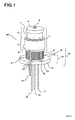
図1は、様々な冷却装置に直ちに取り付けることのできる、代表的なDSCアセンブリ50の正面斜視図である。DSCアセンブリ50は、基本的な部品から構成された炉ブロックアセンブリ1、およびDSC連結アセンブリ19を備えている。本発明のDSC連結アセンブリ19は、広範囲に渡る温度領域において効率的で効果的な測定を行うため、炉ブロックアセンブリ1と様々な冷却装置との連結を可能にする。炉ブロックアセンブリ1は、例示のためのものであり、当業者であれば、異なるデザインの炉ブロックをDSC連結アセンブリ19に連結させてもよいことを理解するであろう。
【0025】
図1に示すように、DSCアセンブリ50の基本的な部品は、炉ブロックアセンブリ1および熱抵抗器9および冷却フランジ10を備えるDSC連結アセンブリ19である。また、図1は、リード線14、15、16およびガス抜き管17を示している。図1のDSCアセンブリ50は、冷却フランジ10において選択された冷却装置と連結させることができる。
【0026】
炉ブロックアセンブリ1は、測定対象であるサンプル及び基準物を載置するととともに、測定の過程で熱的刺激(thermal stimulation)をもたらすDSCセンサ22を内蔵(図2に示す)している。熱抵抗器9は、炉ブロックアセンブリ1から冷却フランジ1へ、さらに冷却装置(図示せず)に至る熱伝導経路を提供する。冷却フランジ10は、炉ブロックアセンブリ1から伝達された熱を受け、それを、冷却フランジ10の表面12と連結する冷却装置に伝達する。また、冷却フランジ10は、DSCアセンブリ50および交換可能な冷却装置との間で、信頼性が高く、標準的な物理的インターフェースを提供する。
【0027】
炉ブロックアセンブリ1は、測定チャンバー2および炉ヒーター3を備えている。サンプルおよび基準物を保持する測定チャンバー2は、ほぼ円筒状の本体を有しており、その本体は、ハンドル5を有するカバー4によって覆われている。測定チャンバー2は、サンプルおよび基準物を内蔵する。動作が行われると、炉ヒーター3は、サンプルおよび基準物を熱するため(基準物が用いられている場合)に測定チャンバー2を加熱する。ほぼ円筒状の炉ヒーター3は、その周囲に電気抵抗を有する一連の巻き線であってセメント6に固定されるもの(図示せず)を備えている。装置の動作範囲に基づき、セメント6を選択することが出来る。例えば、高温での動作を行うには、セラミック製のセメントが好ましい。電流が印加されると、巻き線により熱が発せられ、これが炉ヒーター3から測定チャンバー2に伝えられる。
【0028】
上述のように、炉ブロックアセンブリ1は、実際に設けようとする炉ブロックアセンブリの代表的なものであるが、それは、DSC連結アセンブリ19が与えられた炉ブロックアセンブリと、選ばれた冷却装置とをどのようにして一体化させることができるかを説明する場合の一例にすぎない。当業者であれば、炉ブロックアセンブリ(又はその部品)と冷却装置との間で十分に定義されていて再現性のある熱交換特性を有している限り、他の炉ブロックアセンブリを採用することも可能であることを直ちに理解するであろう。
【0029】
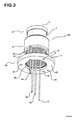
図2は、図1のアセンブリの切り欠き図である。サンプルと基準物を挿入する場合、内カバー32を取り外す。外カバー4は、内カバー32を外の環境から隔離するためのものである。サンプルおよび基準物は、熱流に変換される温度差分を測定する温度検出器を備えたDSCセンサ22上に置かれた皿の中の位置23および24に載置される。温度検出器は、例えば、熱電対であってもよい。熱電対の例としては、Eタイプのクロメルーコンスタンタン熱電対(Type E chromel-constantan thermocouples)がある。他の温度検出器には、プラチナ抵抗の熱電対(platinum resistance thermometers)を含むようにしてもよい。
【0030】
図2を参照すると、巻き線は、上方フランジ27と下方フランジ26の間の薄壁円筒部25に対してスプール状に取り付けられている。かかる加熱構造は、例示のためのものであり、炉ヒーター3を加熱する他の構成を用いることもできる。巻き線に代えて、例えば、加熱片(heating strips)又は他のタイプの加熱素子を用いることもできる。
【0031】
さらに、図1を参照すると、炉ブロックアセンブリ1は、銀等の耐腐食性を有する熱伝導率の高い物質で構成された一体構造であることが好ましい。かかる一体構造と高い熱伝導率により、測定チャンバー2にわたって均等な熱分布を提供することが出来る。温度勾配および温度を不均等にする他の要素は、正確かつ精度の高い測定を阻害することになる。例えば、これらによりサンプルおよび基準物は、別々の温度にさらされることになる。炉ブロックアセンブリ1に一体構造を用いることは、単なる例示にすぎない。所望の熱伝導性/均等性を実現することができ、炉ブロックアセンブリ全体が確実にDSC連結アセンブリ19に連結できるのであれば、2ピース構造又は他の構造を用いるようにしてもよい。
【0032】
熱抵抗器9は、炉ヒーター3と冷却フランジ10との間に十分に定義された熱経路を提供する。周囲温度よりも高い高温テスト中、熱抵抗器9は、冷却フランジ10を介してヒートシンクへの経路を提供する。しかし、熱抵抗器9は、所望の最高温度又は所望の加熱レートに達することが出来なくなるような、冷却負荷(cooling load)を炉ヒーター上に設けることはない。さらに、熱抵抗器9は、動作中に炉ヒーター3および冷却フランジ10が経験する膨張および収縮の差分によって生じる機械的ストレスに耐えるよう設計されている。したがって、破壊および永久的な変形を生じさせることなく前記ストレスに耐えうるような永久熱抵抗器9の素材および構造が選択される。
【0033】
さらに図1を参照すると、ある実施形態において、熱抵抗器9は、1℃から5℃/W(ワット毎の摂氏温度)の範囲の熱抵抗を有するよう設計されているが、約3℃/Wであることが好ましい。この値により、効率よく広い温度プロフィール範囲が達成可能となるよう、DSC連結アセンブリ19を様々な冷却装置とともに用いることが可能となる。例えば、当該値は、周囲温度より高い動作中にフィン付冷却装置を用いて例示した炉ブロックアセンブリ1を適切に冷却するのに十分高い値である。他方、他の冷却装置を用いた周囲温度よりも低い動作が望まれる場合、約3 ℃/Wという値は十分に高いとはいえないので、当該冷却装置に過分な負荷がかかるか、あるいは、炉3からの熱転移が発生するので、炉3は、十分な出力がでない(すなわち、所望の温度および加熱レートを達成するのに十分な出力を作り出すことができない)。
【0034】
所望の熱伝導性に加え、熱抵抗器9は、抗酸性および耐腐食性のみならず機械的強度および復元力(弾性)をも兼ね備えなければならない。かかる特性により、熱抵抗器9の動作寿命を長することができる。
【0035】
例えば、熱抵抗器9は、許容できる熱伝導性、機械的強度、抗酸性および耐腐食性の組み合わせを提供するニッケル合金201等のニッケル合金を用いて構成することができる。所望の温度範囲に適しており、十分な機械的特性を有するのであれば、他の金属および/又は合金を用いてもよい。
【0036】
ここで、熱抵抗器9の構造に目を移すと、ある実施形態において、熱抵抗器9は、炉ヒーター3と冷却フランジ10との間に配された一連の薄部材(thin emmber)31を備えている。この薄部材31の長さおよび厚みは、伸び差(differential expansion)によって生じるひずみが素材の弾性動作範囲(elastic operating range)内に収まるよう決定される。これにより、時間の経過に伴って塑性ひずみが蓄積することによって薄部材31が変形するおそれが小さくなる。
【0037】
ある実施形態において、薄部材31は、直径が約1000分の25から75インチ(0.025インチから0.075インチ)の一連の円筒ロッドであるが、約1000分の50(0.050インチ)の直径のものが好ましい。この例示実施形態において、円筒ロッドの長さは、0.4から1.0インチの範囲であり、約0.7インチであることが好ましい。
【0038】
薄部材31は、その断面が四角形であってもよく、三角形の断面でも、六角形の断面でも、又は、他の形状の断面ものであってもよい。しかし、生産性/コスト面を考慮すると、円筒形状の断面のものを使用することが好ましい。
【0039】
長さ及び直径に関し、特定の値(四角形、三角形、および他の断面形状の寸法)を選択することは、所望の熱抵抗(例えば、3℃/W)および機械的弾性(例えば、−200℃から+725℃の温度範囲で永久的な変形を生じさせない)の両方に関する関数を選択することに相当する。薄部材31の関連する寸法を理論式、コンピュータシミュレーション、又は実証試験(empirical tests)を用いて変更することにより、かかる設計目標値を評価することができる。
【0040】
ここで、冷却フランジ10および炉ヒーター3の構成を参照すると、薄部材31の長手方向の軸は、冷却フランジ10の頂面12および炉ヒーター3の底面に対してほぼ垂直となっている。薄部材31の上端および下端は、ろう付け(brazing)によって、それぞれ炉ヒーター3および冷却フランジ10に連結されているが、他の接続技術を用いるようにしてもよい。
【0041】
図1に示すように、熱抵抗器9を有する一連の薄部材31は、前記冷却フランジ10の内周面又は内周辺に沿って均等な温度を維持するため、前記冷却フランジ10の頂面12上に等間隔に配されているが、他の間隔パターン(四角形、三角形、六角形等)を用いるようにしてもよい。ほぼ均等な間隔にする利点の一つとしては、熱抵抗器9を介して発せられた熱がほぼ均等に冷却フランジ10に伝達されることが挙げられる。このような比較的均等な熱転移が行われることにより、測定チャンバー2内で熱傾斜および温度の不均一が生じるおそれを低下させることができる。
【0042】
ほぼ均等な間隔にする他の利点としては、図1に示したように、薄部材31を円筒状に配置することにより、全体の構造が堅固なものとなることが挙げられる。薄部材31によって定義されるほぼ円筒の配置は、測定動作中の伸縮を十分に吸収するとともに、その後、元の形状に戻る柔軟性を有している。永久的な変形を生じさせることなく動作ストレスを吸収するため、薄部材31の配置を、ほぼ四角形、三角形、六角形、又はその他の形状にしてもよい。
【0043】
図2は、薄部材31を備えた熱抵抗器9の切り欠き図である。図1又は図2に表されてはいないが、熱抵抗器9を他の構造にすることによっても、一連の薄部材31に代えて隣接する円筒状の薄壁(thin-walled cylinder)を定義できることに、注意されたい。かかる円筒状の薄壁は、図1及び図2に示された薄部材の配列によって定義されたものと同様に、前記冷却フランジ10の頂面12上に内周面を定義することが出来る。円筒状の薄壁の壁の厚さは、約1000分の5から50インチ(0.005インチから0.05インチ)の範囲であり、円筒の直径は、1から1.5インチである。また、円筒薄壁の高さは、最低で0.4から1.0インチの範囲である。一般に、前者がよりよいストレス吸収性および復元性を提供するので、円筒薄壁よりも一連部材のほうが好ましい。
【0044】
図1に戻ると、冷却フランジ10は、熱抵抗器9と冷却装置を物理的に接続させる。図1に示すDSCアセンブリ50のデザインにより、広範囲の用途(高温プロフィール、低温プロフィール、高速加熱および冷却等)への使用が可能となるので、作業者は、用途に応じて様々な冷却装置を冷却フランジ10に取り付けることができる。その全てを網羅したわけではないが、冷却フランジ10に接続可能な冷却装置としては、冷却フィン装置(自然又は強制対流)、液冷式熱交換器、ガス冷式熱交換器、および液−ガス相変化熱交換器(change of phase liquid-gas heat exchangers)(開ループ又は閉ループ)が含まれるが、他のタイプの冷却装置を用いることもできる。
【0045】
ある実施形態において、冷却フランジ10は、頂面12、底面13、および、外周辺を定義する側面11を有するほぼ円筒の円盤形状である。冷却フランジ10は、冷却装置と接続するよう構成されており、その一端には、頂面12および側面11に対応する形状の開口部を有している。図1には示されていないが、かかる冷却装置は、通常、自身を炉ブロックアセンブリ1の上でスライド移動させることを可能にする開口を有する円筒形に形成されている。かかる開口は、側面11(冷却装置を所定の場所に保持するため)および頂面12(熱転移および垂直方向の支持のため)の相互に嵌合する。したがって、冷却フランジ10から冷却装置への熱転移は、ほぼ均等に行われ、この場合の主な熱転移経路は、頂面12から(側面11からよりも)冷却装置である。
【0046】
本発明の趣旨および範囲を逸脱することなく、特定の実施形態に基づいて冷却フランジ10の詳細部分のいくつかを変更することもできる。図1においては、冷却フランジ10に、構造全体を支持する支持脚部材(図示せず)を保持する支持穴8が設けられている。ベースサポートへ伸張するかかる支持脚部材は、ステンレス等の熱伝導率の低い管又はロッドであることが好ましい。この低熱伝導率の脚部材は、当該脚を介して冷却フランジ10に流入する熱を最小にする。なお、図1は、冷却フランジ10の温度を監視する温度検出器を底面13に取り付けるための取り付け穴18をも示している。
【0047】
冷却フランジ10は、炉ヒーター3(熱源)を冷却装置(ヒートシンク)に熱的に結合するよう設計されている。したがって、冷却フランジ10は、高い熱伝導性を有するとともに、ある程度の高温および低温において弾性を有していなければならない。また、冷却フランジ10は、その熱交換機能を損なう酸化又は腐食に対する耐性を有していなければならない。上述の課題にちょうどよい妥協点を提供するニッケル合金201等のニッケル合金によって冷却フランジ10を構成してもよいことが判った。例示した冷却フランジ10の寸法には、頂面に沿った直径、約2.37インチ、および側面に沿った厚み、約0.375インチも含まれている。
【0048】
図2に冷却フランジ10の切り欠き図を示す。本実施形態において、底面13は、厚み29に対し、さら穴状(countersunk)に形成される。また、本実施形態において、底面13の前記さら穴の直径は、その周囲に薄部材31が配される頂面12の穴よりもやや大きい。したがって、幅28は、幅30よりもやや狭い程度である。図3に示すように、これにより、薄部材31の下端を厚み29の上で終了させることができる。本実施形態において、底面13における穴と頂面12における穴の直径の差は、薄部材31の直径よりも大きい。
【0049】
図1および図3の例示実施形態のDSCアセンブリ50に示すように、このアセンブリの底面からリード線14、15、16が突出している。ある実施形態において、リード線14は、炉ヒーター3のヒーターコイルに電力を供給するためのヒーターのリード線である。また、リード線15は、炉ブロックアセンブリ1内に位置する温度過昇検出センサ(vertemperture sensor)に接続されている。さらに、リード線16は、測定チャンバー2内の熱電対センサにも接続されている。最後に、ガス抜き管17は、測定チャンバー20のガスを排出する。
【0050】
図4は、本発明の動作環境を示す機能ブロック図である。DSCアセンブリ40は、図1のアセンブリ50と同様のものであり、所望の用途に適した交換可能な冷却装置46と接続されている。前述のように、冷却装置46として、冷却フィン装置、液冷式熱交換器、ガス冷式熱交換器、および相変化熱交換器等を用いるようにしてもよい。DSCアセンブリ40が冷却装置に取り付けられると、ヒーターパワー制御47がヒーターに電力を供給し、冷却制御器48が冷却装置46を動作させる。例えば、冷却装置46が自然対流式の冷却フィンの場合、交換可能な冷却装置46に関する制御条件はもちろん存在しない。
【0051】
制御処理モジュール44は、温度プロフィール入力に従うようDSCアセンブリ40を動作させる制御処理回路を備えている。かかる制御処理モジュール44は、信号増幅及びA/D変換モジュール49から熱/温度測定値を受けとるとともに、プログラムされた温度プロフィールに従うようヒーターパワー制御47を調整する。理論上、制御処理モジュール44は、温度制御プロセスの一部として冷却制御器48に冷却負荷(cooling load)を変更するよう要求することが出来る。しかし、通常の場合、ヒーターパワーを唯一の出力制御パラメーターにすることがより効率的であることが判ったので、制御処理モジュール44により冷却制御器48が制御されることはない。DSCアセンブリ40からの温度センサ出力は、信号増幅及びA/D変換モジュール49により増幅され、デジタルフォーマットに変換され、制御処理モジュール44(測定値を更に処理し、これらをコンピュータ画面上、プロッター又はハードコピープリンターからグラフ等として出力するためフォーマットすることもできる)によって読み取られる。
【0052】
当業者であれば、図4のブロックは、機能を表したものにすぎず、特定の機能については組み合わせたり、または、更に分割することができることを、直ちに認識するであろう。例えば、制御処理モジュール44、ヒーターパワー制御47および信号増幅及びA/D変換モジュール49の動作は、1のプログラムされた、又は、特別なアプリケーションコンピューターによって実行することが可能である。
【0053】
ほぼ円筒の冷却フランジに結合された配置薄部材の熱抵抗器を用いた改良DSCアセンブリに関して説明したが、当業者にとって、かかる構造を介して多くの利点が生じることは明らかであろう。このデザインは、それ自身の熱流特性の範囲で丈夫であり、その形状により多くの冷却装置を用いることが出来る。ユーザーは、特定のテスト条件に応じ、ある冷却装置を容易に他の冷却装置と交換することができる。
【0054】
他の利点としては、正確かつ精度の高い測定を行うため、配置薄部材が、均一で再現性の高い冷却動作を提供できることにある。更に、熱抵抗器の物理的構造は、ヒーターの膨張と冷却フランジの収縮が同時に起こってもそれらに耐え得る頑丈さを有している。しかも、熱抵抗器は、弾力性に富み、かかる機械的ストレスが加わって後でも元の形状に戻るという利点がある。
【0055】
熱ヒーターを測定チャンバーと冷却装置の間に位置させたことも、本発明における他の利点である。かかる配置によって、ヒートシンク(冷却フランジ/冷却装置)に向かって流れる熱が、測定チャンバーに向かわないので、温度の不均性という問題が大きく緩和される。
【0056】
要するに、デザイン全体の信頼性の高さによって、広範囲にわたる熱プロフィール、高加熱と高冷却レート、低騒音かつ低消費電力のDSC測定、が可能となるとともに他の利点や利益も存在する。
【0057】
ここではシステムおよび方法の実施形態について説明がなされたが、上述の記載は説明をその目的とすることから、本発明を完全に理解させるため、詳細について多くの特定がなされていた。しかし、当業者であれば、かかる特定事項なしでも本発明の実施が可能であることを理解するであろう。また、前記詳細な説明において、本発明は、特例の例示実施形態を参照して説明された。かかる特定の実施形態は、単なる例示にすぎず、したがって、明細書および図面は、制限的ではなく例示目的であると理解されたい。
【図面の簡単な説明】
【図1】本発明の好ましい実施形態の傾斜正面図である。
【図2】本発明の好ましい実施形態の回転切り欠け図である。
【図3】本発明の好ましい実施形態の傾斜底面図である。
【図4】本発明の好ましい実施形態の動作環境を示す機能ブロック図である。[0001]
[Field of the Invention]
The present invention relates to the fields of differential thermal analysis and differential scanning calorimetry.
[0002]
BACKGROUND OF THE INVENTION
In general, a calorimetric technique for measuring physical properties of an object by exposing it to different temperature ranges is called differential thermal analysis (DTA). DTA is phase change, glass transitions, polymerization / depolymerization, crystallization, softening, sublimation, dehydration, decomposition, oxidation, cure kinetics. It is used to measure parameters related to kinetics). A differential scanning calorimeter (DSC) measures temperature and heat flow with energy dissipation and energy absorption (exothermic and endothermic respectively). DSC is widely used for research in academic, governmental and private institutions, and for quality control and production purposes.
[0003]
In the following, DSC will be described as an example, but it will be understood that this description also applies to DTA.
[0004]
In general, a DSC measuring device is a basic part of a heating measurement chamber including a sensor assembly on which an object to be measured (the “sample”) is placed, a furnace heater for heating the measuring heater, and a cooling device. It has. The cooling device functions as a heat sink for the furnace heater. This cooling device can also be used when the temperature in the measurement chamber rises or falls.
[0005]
A typical DSC measurement device also includes a control circuit that controls the furnace heater / cooling device to match the temperature in the measurement chamber to the programmed temperature profile. Further, in order to display the measurement value, the DSC measurement apparatus may be provided with output means such as a printer, a video screen, or a plotter. Such measurement results can be absolute temperature vs. temperature difference or heat flow (eg watts per gram) vs.
It can be expressed as a curve showing the absolute temperature.
[0006]
In conventional DSC analysis, the measurement chamber holds relevant samples and standards that are exposed to a programmed temperature profile. References are generally more inactive with the associated profile or otherwise less well understood.
[0007]
Usually, since the DSC analysis does not actually use a reference material, the reference material holding dish remains empty.
[0008]
The sample and reference are mounted on a DSC sensor assembly that includes a sample position temperature detector and a reference position temperature detector. These two temperature detectors are usually configured so that the temperature difference between the sample position and the reference object position can be measured directly. A basic DSC apparatus is shown in FIG. 1b of US Pat. No. 5,224,775 (the '775 patent) by Reading et al. FIG. 1 of US Pat. No. 3,456,490 ('490 patent) by Stone shows another configuration of a basic DSC apparatus.
[0009]
During operation, the furnace heater and / or cooling device is controlled to follow a programmed temperature profile. The temperature difference ΔT between the sample and the reference (ie the incoming or outgoing heat flow) is calculated as a function of the measured sample temperature. In order to better understand the characteristics and properties of the sample, we observed the results of a rapid change in temperature difference ΔT, such as when the sample undergoes a phase change or chemical reaction.
[0010]
Such thermal analysis techniques also have other aspects such as pressure differential scanning calorimeter (PDSC), pressure differential thermal analyzer (PDTA), photo-calorimetry (DPC), and pressure-differential photo-calorimetry. The present invention described later can also be used in these embodiments well known in the art.
[0011]
As will be readily appreciated, a DSC device is designed that provides an acceptable combination of attributes with respect to temperature profile range, cooling and heating rate (how fast the measurement chamber can be cooled or heated), accuracy, precision, etc. This is a significant challenge. The temperature profile for the calorimeter disclosed in the '775 patent can range, for example, from a minimum of −150 ° C. to a maximum of + 725 ° C., US patent application Ser. Nos. 09 / 643,870 and 09 / 643,869. The temperature profile for a calorimeter disclosed in US patent application Ser. No. 09 / 767,903, filed Jan. 24, 2001, which is a continuation-in-part of the application, should be in the range from -200 ° C to + 725 ° C Can do. Conventional DSC devices may have an undesirable trade-off between the attributes.
[0012]
Conventional devices also have other drawbacks. For example, it is preferable to keep the temperature of the measurement chamber uniform so that the sample and the reference are exposed to the same thermal stimulus. Furthermore, prior art designs are susceptible to temperature changes or temperature gradients in the measurement chamber. It is difficult to predict / measure such non-uniform temperatures so that they can be compensated by signal processing. Therefore, this phenomenon causes a measurement error.
[0013]
In conventional designs, it has also been difficult to achieve an acceptable balance between high cooling rate and temperature uniformity. For example, such a design can increase the cooling rate, but tends to sacrifice temperature uniformity.
[0014]
Finally, conventional designs do not immediately contribute to a modular structure that allows parts to be easily and quickly replaced to change DSC equipment depending on the application. Even if the conventional structure physically allows the modular replacement of parts (such as replacing the first type of cooling device with the second type of cooling device), such modules are subject to the original design characteristics of the conventional structure. The advantage of sex is severely limited. For example, the DSC unit may couple a “cooling fin” device to the measurement chamber / furnace heater to provide a heat sink during a “hot” measurement above ambient temperature. Such applications are then modified so that a “cold” measurement is desired that is approximately lower than the ambient temperature. Conventional designs may physically allow the cooling fin device to be replaced with a high-power “liquid-cooled heat exchanger”. However, depending on the characteristics of conventional designs (eg, very inefficient heat transfer paths), the desired low temperature operation cannot be performed even with a more efficient cooling system.
[0015]
SUMMARY OF THE INVENTION
In order to overcome these shortcomings or disadvantages in the prior art and to implement and outline based on the objectives of the present invention, certain embodiments of the present invention may be referred to as furnace block assemblies ("DSC cells"). A DSC connection assembly for connecting a cooling chamber with a furnace heater for heating a measurement chamber containing a DSC sensor on which the sample and reference are mounted. Such a DSC connection assembly includes a distributed thermal resistor attached to the cooling flange.
[0016]
This distributed thermal resistor has a thermal characteristic that can moderately adjust the heat flow between the furnace heater and the cooling flange so that experiments can be performed in various temperature ranges ranging from high to low. Distributed thermal resistors have the mechanical property of being resistant to mechanical strains caused by the relative motion (expansion and contraction) of the operating furnace assembly and cooling flange without causing permanent deformation. ing.
[0017]
The cooling flange of the DSC connection assembly is connected to a thermal resistor. Such cooling flanges have the thermal characteristics of allowing an even and efficient heat flow through the thermal resistor and adjusting the heat conduction appropriately. Further, the cooling flange has a mechanical characteristic that it has a standard shape that can be easily combined with various cooling devices. When the selected cooling device is attached to the cooling flange, the physical contact between the measuring chamber and the cooling device and the heat flow path are well defined and reproducible.
[0018]
The DSC coupling assembly of the present invention has many advantages. Since the heat flow is distributed and regulated via the thermal resistor, it is possible to use various cooling devices for performing experiments in various temperature ranges. Such a structure of the thermal resistor makes it possible to provide a connection assembly that has elasticity and has a long life without causing permanent deformation due to operating stress. Efficient and even heat flow through the thermal resistor can achieve the desired cooling and heating rate while maximizing temperature uniformity within the measurement chamber. Such characteristics also allow the DSC connection assembly to be used over a wide temperature range. This cooling flange construction also has the advantage that the selected cooling device can be mounted in such a way as to minimize undesired heat flow from the measurement chamber.In addition, the thermal resistor is well defined from the furnace heater to the cooling flange (well defined) A thermal transfer pathway can be provided.
[0019]
Accordingly, it is an object of the present invention to provide a DSC connection assembly that can perform well-defined and reproducible thermal transitions.
[0020]
It is another object of the present invention to provide a DSC coupling assembly that can be used in a wide temperature range with a steeper heating and cooling rate than that achieved in the prior art.
[0021]
It is yet another object of the present invention to provide a DSC connection assembly with improved temperature uniformity.
[0022]
It is an object of a preferred embodiment of the present invention to provide a DSC linkage assembly having a modular structure that can be operated efficiently using a plurality of easily replaceable cooling devices.
[0023]
These and other objects of the present invention will be described in detail in the following description of the invention, the appended drawings and the appended claims.
[0024]
DESCRIPTION OF THE INVENTION
FIG. 1 is a front perspective view of an
[0025]
As shown in FIG. 1, the basic parts of the
[0026]
The furnace block assembly 1 has a built-in DSC sensor 22 (shown in FIG. 2) on which a sample and a reference object to be measured are placed and which provides thermal stimulation in the measurement process. The thermal resistor 9 provides a heat conduction path from the furnace block assembly 1 to the cooling flange 1 and further to a cooling device (not shown). The cooling
[0027]
The furnace block assembly 1 includes a measurement chamber 2 and a furnace heater 3. The measurement chamber 2 holding the sample and the reference object has a substantially cylindrical main body, and the main body is covered with a cover 4 having a handle 5. The measurement chamber 2 contains a sample and a reference object. When the operation is performed, the furnace heater 3 heats the measurement chamber 2 to heat the sample and the reference (when the reference is used). The substantially cylindrical furnace heater 3 is provided with a series of windings having electric resistance around it (not shown) fixed to the cement 6. Cement 6 can be selected based on the operating range of the device. For example, ceramic cement is preferred for operation at high temperatures. When an electric current is applied, heat is generated by the winding, and this is transmitted from the furnace heater 3 to the measurement chamber 2.
[0028]
As described above, the furnace block assembly 1 is representative of the actual furnace block assembly to be provided, which includes a furnace block assembly provided with a
[0029]
FIG. 2 is a cutaway view of the assembly of FIG. When inserting a sample and a reference object, the
[0030]
Referring to FIG. 2, the winding is attached to the thin wall cylindrical portion 25 between the
[0031]
Further, referring to FIG. 1, the furnace block assembly 1 is preferably a monolithic structure made of a highly heat-conductive material having corrosion resistance such as silver. Such an integrated structure and high thermal conductivity can provide an even heat distribution across the measurement chamber 2. Temperature gradients and other factors that make temperature uneven will interfere with accurate and accurate measurements. For example, these expose the sample and the reference to separate temperatures. The use of a unitary structure for the furnace block assembly 1 is merely illustrative. A two piece structure or other structure may be used as long as the desired thermal conductivity / uniformity can be achieved and the entire furnace block assembly can be reliably connected to the
[0032]
The thermal resistor 9 provides a well-defined thermal path between the furnace heater 3 and the cooling
[0033]
Still referring to FIG. 1, in one embodiment, the thermal resistor 9 is designed to have a thermal resistance in the range of 1 ° C. to 5 ° C./W (degrees Centigrade per watt), but about 3 ° C. / W is preferable. This value allows the
[0034]
In addition to the desired thermal conductivity, the thermal resistor 9 must have not only acid and corrosion resistance but also mechanical strength and restoring force (elasticity). Due to such characteristics, the operating life of the thermal resistor 9 can be extended.
[0035]
For example, the thermal resistor 9 can be constructed using a nickel alloy, such as nickel alloy 201, that provides a combination of acceptable thermal conductivity, mechanical strength, acid resistance, and corrosion resistance. Other metals and / or alloys may be used as long as they are suitable for the desired temperature range and have sufficient mechanical properties.
[0036]
Turning now to the structure of the thermal resistor 9, in one embodiment, the thermal resistor 9 includes a series of
[0037]
In certain embodiments, the
[0038]
The
[0039]
With regard to length and diameter, selecting specific values (square, triangular, and other cross-sectional dimensions) can result in desired thermal resistance (eg, 3 ° C / W) and mechanical elasticity (eg, -200 ° C). Is equivalent to selecting a function for both of which does not cause permanent deformation in the temperature range from to + 725 ° C. By changing the relevant dimensions of the
[0040]
Here, referring to the configuration of the cooling
[0041]
As shown in FIG. 1, a series of
[0042]
Another advantage of the substantially uniform spacing is that, as shown in FIG. 1, the
[0043]
FIG. 2 is a cutaway view of the thermal resistor 9 including the
[0044]
Returning to FIG. 1, the cooling
[0045]
In one embodiment, the cooling
[0046]
Some of the details of the cooling
[0047]
The cooling
[0048]
FIG. 2 shows a cutaway view of the cooling
[0049]
As shown in the exemplary
[0050]
FIG. 4 is a functional block diagram showing the operating environment of the present invention.
[0051]
The
[0052]
Those skilled in the art will immediately recognize that the blocks of FIG. 4 are merely representative of functions, and that certain functions can be combined or further divided. For example, the operations of the
[0053]
Although described with respect to an improved DSC assembly using a thin plate thermal resistor coupled to a generally cylindrical cooling flange, it will be apparent to those skilled in the art that many advantages arise through such a structure. This design is robust within its own range of heat flow characteristics, and more cooling devices can be used due to its shape. The user can easily replace one cooling device with another cooling device, depending on the specific test conditions.
[0054]
Another advantage is that the thin placement member can provide a uniform and highly reproducible cooling operation for accurate and accurate measurements. Furthermore, the physical structure of the thermal resistor is robust enough to withstand the simultaneous expansion of the heater and contraction of the cooling flange. Moreover, the thermal resistor has an advantage that it is rich in elasticity and returns to its original shape even after such mechanical stress is applied.
[0055]
It is another advantage of the present invention that a thermal heater is located between the measurement chamber and the cooling device. With such an arrangement, the heat flowing toward the heat sink (cooling flange / cooling device) does not go to the measurement chamber, which greatly reduces the problem of temperature non-uniformity.
[0056]
In short, the overall reliability of the design allows for a wide range of thermal profiles, high heating and cooling rates, low noise and low power DSC measurements, and other benefits and benefits.
[0057]
While embodiments of the system and method have been described herein, the above description is for purposes of illustration and many details have been specified in order to provide a thorough understanding of the present invention. However, one skilled in the art will understand that the invention may be practiced without such specific details. Also, in the foregoing detailed description, the invention has been described with reference to specific exemplary embodiments. It is to be understood that such specific embodiments are merely exemplary and that the specification and drawings are for purposes of illustration and not limitation.
[Brief description of the drawings]
FIG. 1 is an inclined front view of a preferred embodiment of the present invention.
FIG. 2 is a rotational cutaway view of a preferred embodiment of the present invention.
FIG. 3 is an inclined bottom view of a preferred embodiment of the present invention.
FIG. 4 is a functional block diagram illustrating an operating environment of a preferred embodiment of the present invention.
Claims (24)
前記測定チャンバーを加熱するため前記測定チャンバーに対して動作可能に接続された炉ヒーター、
前記測定チャンバーに対するヒートシンクとして動作する冷却フランジ、および、
一連の縦長部材(longitudinal members)を備えた熱抵抗器、
を備えた差分走査熱量計であって、
前記冷却フランジは、
ほぼ平坦な頂面、底面、および外周を定義する側面を有するほぼ円筒形のディスクを備えており、また、
前記一連の縦長部材は、
前記頂面に対しほぼ垂直に配置されるとともに、前記冷却フランジの内周辺(inner periphery)に沿ってほぼ円形パターンを構成すること、
を特徴とするもの。Measuring chamber for storing samples,
A furnace heater operatively connected to the measurement chamber for heating the measurement chamber;
A cooling flange that acts as a heat sink for the measurement chamber; and
A thermal resistor with a series of longitudinal members,
A differential scanning calorimeter comprising
The cooling flange is
A substantially cylindrical disk having a substantially flat top surface, a bottom surface, and side surfaces defining an outer periphery, and
The series of longitudinal members are:
Being arranged substantially perpendicular to the top surface and forming a substantially circular pattern along the inner periphery of the cooling flange;
It is characterized by.
前記縦長部材は、
ほぼ円筒形のロッドであること、
を特徴とするもの。The calorimeter of claim 1, wherein
The longitudinal member is
Being a substantially cylindrical rod,
It is characterized by.
前記縦長部材は、
四角形、六角形、又は三角形のいずれかの断面を有するロッドを備えたこと、
を特徴とするもの。The calorimeter of claim 1, wherein
The longitudinal member is
A rod having a square, hexagonal, or triangular cross section;
It is characterized by.
前記縦長部材は、
約0.025から約0.075インチの範囲の直径を有すること、
を特徴とするもの。In any one of the calorimeters of Claims 1-3,
The longitudinal member is
Having a diameter in the range of about 0.025 to about 0.075 inches;
It is characterized by.
前記縦長部材は、
約0.05インチの直径を有すること、
を特徴とするもの。In any one of the calorimeters of Claims 1-4,
The longitudinal member is
Having a diameter of about 0.05 inches;
It is characterized by.
前記縦長部材は、
約0.4から約1インチの範囲の長さを有すること、
を特徴とするもの。In any of the calorimeters of Claims 1-5,
The longitudinal member is
Having a length in the range of about 0.4 to about 1 inch;
It is characterized by.
前記縦長部材は、
約0.7インチの長さを有すること、
を特徴とするもの。In any one of the calorimeters of Claims 1-6,
The longitudinal member is
Having a length of about 0.7 inches;
It is characterized by.
前記熱抵抗器は、
ニッケル合金で構成されていること、
を特徴とするもの。In any one of the calorimeters of Claims 1-7,
The thermal resistor is
Made of nickel alloy,
It is characterized by.
前記熱抵抗器は、
約1から約5℃/Wの範囲の熱抵抗を有し、前記炉ヒーターから前記冷却フランジへの熱転移経路を形成するために前記炉ヒーターと前記冷却フランジ間に配されていること、
を特徴とするもの。In any one of the calorimeters of Claims 1-8,
The thermal resistor is
Having a thermal resistance in the range of about 1 to about 5 ° C./W, and disposed between the furnace heater and the cooling flange to form a heat transfer path from the furnace heater to the cooling flange;
It is characterized by.
前記縦長部材のそれぞれは、
上端および下端を有しており、
前記縦長部材の前記下端は、
隣接する前記縦長部材の各ペア間の距離がほぼ同じ距離になるよう間隔を空けて前記冷却フランジの前記ほぼ平坦な頂面上に配されていること、
を特徴とするもの。In any of the calorimeters of Claims 1-9,
Each of the longitudinal members is
Has an upper end and a lower end,
The lower end of the longitudinal member is
Being disposed on the substantially flat top surface of the cooling flange with a spacing so that the distance between each pair of adjacent longitudinal members adjacent to each other is substantially the same distance;
It is characterized by.
前記縦長部材のそれぞれは、
上端および下端を有しており、
前記下端は、
前記冷却フランジの前記ほぼ平坦な頂面で終了すること、
を特徴とするもの。In any one of the calorimeters of Claims 1-10,
Each of the longitudinal members is
Has an upper end and a lower end,
The lower end is
Ending at the substantially flat top surface of the cooling flange;
It is characterized by.
前記炉ヒーターは、
前記測定チャンバーと前記熱抵抗器の間に設けられていること、
を特徴とするもの。In any one of the calorimeters of Claims 1-11,
The furnace heater is
Provided between the measurement chamber and the thermal resistor;
It is characterized by.
前記熱抵抗器は、
測定動作中にはひずみ、さらに、
前記熱抵抗器は、
周囲温度に戻ると、元の形状(nominal shape)に戻ること、
を特徴とするもの。In any one of the calorimeters of Claims 1-12,
The thermal resistor is
Strain during the measurement operation,
The thermal resistor is
When it returns to ambient temperature, it returns to its original shape (nominal shape)
It is characterized by.
前記測定チャンバーを加熱するための炉、
前記炉と冷却フランジとの間に配置される熱抵抗器であって、一連の縦長部材(longitudinal members)を備えた熱抵抗器、
を備えた差分走査熱量計であって、
前記冷却フランジは、
ほぼ平坦な頂面、底面、および外周を定義する側面を有するほぼ円筒形のディスクを備えており、また、
前記一連の縦長部材は、
前記頂面に対しほぼ垂直に配置されるとともに、前記冷却フランジの内周辺(inner periphery)に沿ってほぼ円形パターンを構成すること、
を特徴とするもの。Measuring chamber for storing samples,
A furnace for heating the measuring chamber;
A thermal resistor disposed between the furnace and the cooling flange, the thermal resistor comprising a series of longitudinal members;
A differential scanning calorimeter comprising
The cooling flange is
A substantially cylindrical disk having a substantially flat top surface, a bottom surface, and side surfaces defining an outer periphery, and
The series of longitudinal members are:
Being arranged substantially perpendicular to the top surface and forming a substantially circular pattern along the inner periphery of the cooling flange;
It is characterized by.
前記縦長部材は、
円形の断面を有すること、
を特徴とするもの。In any of the calorimeters of Claim 14,
The longitudinal member is
Having a circular cross section,
It is characterized by.
前記縦長部材は、
四角形の断面を有すること、
を特徴とするもの。In any of the calorimeters of Claim 14,
The longitudinal member is
Having a rectangular cross section,
It is characterized by.
前記熱抵抗器は、
約0.2から約1W/℃の範囲の熱伝導率を有すること、
を特徴とするもの。In any one of the calorimeters of Claims 14-16,
The thermal resistor is
Having a thermal conductivity in the range of about 0.2 to about 1 W / ° C;
It is characterized by.
前記縦長部材は、
上端および下端を有しており、
前記冷却フランジは、
ほぼ平坦な頂面を有し、
前記縦長部材の前記下端は、
隣接する前記縦長部材の各ペア間の距離がほぼ同じ距離になるよう間隔を空けて前記冷却フランジの前記ほぼ平坦な頂面上に配されていること、
を特徴とするもの。The calorimeter according to any one of claims 14 to 17,
The longitudinal member is
Has an upper end and a lower end,
The cooling flange is
Has a substantially flat top surface,
The lower end of the longitudinal member is
Being disposed on the substantially flat top surface of the cooling flange with a spacing so that the distance between each pair of adjacent longitudinal members adjacent to each other is substantially the same distance;
It is characterized by.
当該取り付け具は、
一連の縦長部材を有する熱抵抗器および前記冷却装置に熱を転移させるため、前記炉アセンブリに接続するよう構成されたフランジを備えており、
前記冷却フランジは、
頂面、底面、および外周を定義する側面を有するほぼ円筒形のディスクを有し、
前記縦長部材のそれぞれは、
上端および下端を有しており、
前記下端は、
前記頂面の内周辺(inner periphery)に沿って前記前記円筒ディスクの前記頂面に接続されること、
を特徴とするもの。A fitting for coupling a furnace assembly having a measurement chamber and a furnace heater to a cooling device,
The fitting is
A thermal resistor having a series of longitudinal members and a flange configured to connect to the furnace assembly for transferring heat to the cooling device;
The cooling flange is
Having a generally cylindrical disc having a top surface, a bottom surface, and side surfaces defining an outer periphery;
Each of the longitudinal members is
Has an upper end and a lower end,
The lower end is
Connected to the top surface of the cylindrical disk along an inner periphery of the top surface;
It is characterized by.
前記熱抵抗器は、
測定動作中にはひずみ、さらに、周囲温度に戻ると、元の形状(nominal shape)に戻ること、
を特徴とするもの。The fitting of claim 19,
The thermal resistor is
Strain during the measurement operation, and when it returns to ambient temperature, it returns to its original shape (nominal shape),
It is characterized by.
前記熱抵抗器は、
約0.2から約1W/℃の範囲の熱伝導率を有すること、
を特徴とするもの。Any of the attachments of claim 19 .
The thermal resistor is
Having a thermal conductivity in the range of about 0.2 to about 1 W / ° C;
It is characterized by.
前記フランジは、
ほぼ平坦な前記頂面を有し、
前記縦長部材の前記下端は、
隣接する前記縦長部材の各ペア間の距離がほぼ同じ距離になるよう間隔を空けて前記冷却フランジの前記ほぼ平坦な頂面上に配されていること、
を特徴とするもの。The fitting of claim 19,
The flange is
Having a substantially flat top surface;
The lower end of the longitudinal member is
Being disposed on the substantially flat top surface of the cooling flange with a spacing so that the distance between each pair of adjacent longitudinal members adjacent to each other is substantially the same distance;
It is characterized by.
当該取り付け具は、
一連の縦長部材を有する熱抵抗器および前記冷却装置に熱を転移させるため、前記炉アセンブリに接続するよう構成されたフランジを備えており、
前記フランジは、
前記取り付け具を前記冷却装置に連結する手段を備え、
前記フランジは、
ほぼ平坦な頂面、底面、および外周を定義する側面を有するほぼ円筒形のディスクを備えており、また、
前記一連の縦長部材は、
前記頂面に対しほぼ垂直に配置されるとともに、前記フランジの内周辺(inner periphery)に沿ってほぼ円形パターンを構成すること、
を特徴とするもの。A fitting for coupling a furnace assembly having a measurement chamber and a furnace heater to a cooling device,
The fitting is
A thermal resistor having a series of longitudinal members and a flange configured to connect to the furnace assembly for transferring heat to the cooling device;
The flange is
Means for connecting the fixture to the cooling device;
The flange is
A substantially cylindrical disk having a substantially flat top surface, a bottom surface, and side surfaces defining an outer periphery, and
The series of longitudinal members are:
Being arranged substantially perpendicular to the top surface and forming a substantially circular pattern along the inner periphery of the flange;
It is characterized by.
前記縦長部材は、さらに、
上端および下端を有しており、
前記縦長部材の前記下端は、
隣接する前記縦長部材の各ペア間の距離がほぼ同じ距離になるよう間隔を空けて前記フランジの前記ほぼ平坦な頂面上に配されていること、
を特徴とするもの。24. The attachment of claim 23, wherein
The longitudinal member further includes:
Has an upper end and a lower end,
The lower end of the longitudinal member is
Being arranged on the substantially flat top surface of the flange with a spacing so that the distance between each pair of adjacent longitudinal members adjacent to each other is substantially the same distance;
It is characterized by.
Applications Claiming Priority (2)
| Application Number | Priority Date | Filing Date | Title |
|---|---|---|---|
| US09/769,320 | 2001-01-26 | ||
| US09/769,320 US6523998B1 (en) | 2001-01-26 | 2001-01-26 | Thermal analysis assembly with distributed resistance and integral flange for mounting various cooling devices |
Publications (3)
| Publication Number | Publication Date |
|---|---|
| JP2002310965A JP2002310965A (en) | 2002-10-23 |
| JP2002310965A5 JP2002310965A5 (en) | 2005-11-04 |
| JP4181776B2 true JP4181776B2 (en) | 2008-11-19 |
Family
ID=25085106
Family Applications (1)
| Application Number | Title | Priority Date | Filing Date |
|---|---|---|---|
| JP2002017997A Expired - Lifetime JP4181776B2 (en) | 2001-01-26 | 2002-01-28 | Thermal analysis assembly with distributed thermal resistors and integrated flange for mounting various cooling devices |
Country Status (3)
| Country | Link |
|---|---|
| US (1) | US6523998B1 (en) |
| EP (1) | EP1227317B1 (en) |
| JP (1) | JP4181776B2 (en) |
Families Citing this family (16)
| Publication number | Priority date | Publication date | Assignee | Title |
|---|---|---|---|---|
| US20050036536A1 (en) * | 2001-09-18 | 2005-02-17 | Lewis Edwin A. | High throughout energy array |
| JP4116526B2 (en) * | 2003-11-18 | 2008-07-09 | エスアイアイ・ナノテクノロジー株式会社 | Differential scanning calorimeter with second heater |
| US7125163B2 (en) * | 2003-11-24 | 2006-10-24 | The Boeing Company | Simple high accuracy high energy calorimeter |
| US7371006B2 (en) * | 2004-02-10 | 2008-05-13 | Perkinelmer Las, Inc. | Differential scanning calorimeter (DSC) with temperature controlled furnace |
| US7481575B2 (en) * | 2005-05-05 | 2009-01-27 | Leco Corporation | Calorimeter |
| JP4868305B2 (en) * | 2006-01-27 | 2012-02-01 | エスアイアイ・ナノテクノロジー株式会社 | Differential scanning calorimeter |
| FR2917163B1 (en) * | 2007-06-06 | 2015-10-23 | Waters Investments Ltd | INFRARED HEAT DIFFERENTIAL SCALING CALORIMETER |
| GB2462954B (en) * | 2007-06-06 | 2011-08-17 | Waters Investments Ltd | System and method for thermal analysis using variable thermal resistance |
| US8087821B2 (en) * | 2007-06-06 | 2012-01-03 | Waters Technologies Corporation | Infrared heated differential scanning calorimeter |
| US8418480B2 (en) * | 2008-12-18 | 2013-04-16 | Waters Technologies Corporation | Cooling system using positive displacement cryogenic liquid pump |
| JP5283535B2 (en) * | 2009-02-20 | 2013-09-04 | 株式会社日立ハイテクサイエンス | Differential scanning calorimeter |
| EP2325628B1 (en) * | 2009-11-23 | 2013-06-26 | Mettler-Toledo AG | Thermal analysis device |
| CN103542946B (en) * | 2012-07-12 | 2016-03-09 | 中国石油天然气股份有限公司 | A kind of temperature sensing assembly |
| JP5551811B2 (en) * | 2013-05-24 | 2014-07-16 | 株式会社日立ハイテクサイエンス | Differential scanning calorimeter |
| JP6841425B2 (en) * | 2017-05-26 | 2021-03-10 | 株式会社リガク | Thermal analyzer |
| US10755200B2 (en) | 2017-09-22 | 2020-08-25 | International Business Machines Corporation | Automated control of circumferential variability of blast furnace |
Family Cites Families (26)
| Publication number | Priority date | Publication date | Assignee | Title |
|---|---|---|---|---|
| US3339398A (en) | 1964-03-30 | 1967-09-05 | Chevron Res | High sensitivity differential thermal analysis apparatus and method |
| US3456490A (en) | 1967-04-21 | 1969-07-22 | Tracor | Differential thermal analysis |
| GB1259453A (en) | 1968-01-25 | 1972-01-05 | ||
| US3774078A (en) * | 1972-03-29 | 1973-11-20 | Massachusetts Inst Technology | Thermally integrated electronic assembly with tapered heat conductor |
| US3813937A (en) * | 1972-06-16 | 1974-06-04 | J Fletcher | Heat flow calorimeter |
| CH573114A5 (en) | 1974-06-25 | 1976-02-27 | Mettler Instrumente Ag | |
| US4050302A (en) * | 1975-02-10 | 1977-09-27 | Aluminum Company Of America | Thermoelectric heat flow transducer |
| JPH0765974B2 (en) | 1988-10-26 | 1995-07-19 | セイコー電子工業株式会社 | Cooling device for heating furnace of thermal analyzer |
| US5224538A (en) * | 1991-11-01 | 1993-07-06 | Jacoby John H | Dimpled heat transfer surface and method of making same |
| US5224775C2 (en) | 1992-03-02 | 2002-04-23 | Ta Instr Inc | Method and apparatus for modulated differential analysis |
| US5711604A (en) * | 1993-12-14 | 1998-01-27 | Seiko Instruments Inc. | Method for measuring the coefficient of heat conductivity of a sample |
| US5509733A (en) * | 1993-12-21 | 1996-04-23 | Ta Instruments, Inc. | Infrared heated differential thermal analyzer |
| US5484204A (en) | 1994-09-21 | 1996-01-16 | Ta Instruments, Inc. | Mechanical cooling system |
| KR0156622B1 (en) * | 1995-04-27 | 1998-10-15 | 문정환 | Semiconductor leadframe and the manufacturing method |
| DE69630927T2 (en) * | 1995-09-07 | 2004-05-19 | The Perkin-Elmer Corp., Norwalk | Thermal insulation for LPG containers |
| US5876118A (en) | 1995-12-08 | 1999-03-02 | The Perkin-Elmer Corporation | Calorimeter having rapid cooling of a heating vessel therein |
| JPH1054813A (en) | 1996-08-08 | 1998-02-24 | Shimadzu Corp | Parallax scanning calorimetry device |
| JPH10132770A (en) | 1996-10-31 | 1998-05-22 | Shimadzu Corp | Thermal analysis apparatus |
| JPH10246577A (en) | 1997-03-03 | 1998-09-14 | Rigaku Corp | Method and system for cooling heating furnace |
| US6694731B2 (en) * | 1997-07-15 | 2004-02-24 | Deka Products Limited Partnership | Stirling engine thermal system improvements |
| JP2000174182A (en) * | 1998-12-08 | 2000-06-23 | Nec Eng Ltd | Heat sink |
| US6238613B1 (en) * | 1999-07-14 | 2001-05-29 | Stratasys, Inc. | Apparatus and method for thermoplastic extrusion |
| US6308518B1 (en) * | 1999-09-28 | 2001-10-30 | Rick C. Hunter | Thermal barrier enclosure system |
| US6428203B1 (en) * | 2000-03-23 | 2002-08-06 | Ta Instruments, Inc. | Power compensation differential scanning calorimeter |
| WO2002006803A1 (en) * | 2000-07-13 | 2002-01-24 | Igc-Apd Cryogenics, Inc. | Cooling system for thermal analysis |
| US20020163781A1 (en) * | 2001-05-01 | 2002-11-07 | Ericsson Inc. | Integrated cooling of a printed circuit board structure |
-
2001
- 2001-01-26 US US09/769,320 patent/US6523998B1/en not_active Expired - Lifetime
-
2002
- 2002-01-22 EP EP02001504.6A patent/EP1227317B1/en not_active Expired - Lifetime
- 2002-01-28 JP JP2002017997A patent/JP4181776B2/en not_active Expired - Lifetime
Also Published As
| Publication number | Publication date |
|---|---|
| EP1227317A3 (en) | 2004-02-04 |
| JP2002310965A (en) | 2002-10-23 |
| US6523998B1 (en) | 2003-02-25 |
| EP1227317B1 (en) | 2014-09-03 |
| EP1227317A2 (en) | 2002-07-31 |
Similar Documents
| Publication | Publication Date | Title |
|---|---|---|
| JP4181776B2 (en) | Thermal analysis assembly with distributed thermal resistors and integrated flange for mounting various cooling devices | |
| JP5509195B2 (en) | Thermal conductivity measuring device and thermal conductivity measuring method | |
| JP3936847B2 (en) | Modulated differential scanning calorimeter | |
| US7470057B2 (en) | Differential scanning calorimeter sensor and method | |
| JP4868305B2 (en) | Differential scanning calorimeter | |
| JP2008530560A (en) | Differential scanning calorimeter (DSC) with temperature controlled furnace | |
| JP4831487B2 (en) | Differential scanning calorimeter | |
| JP5642525B2 (en) | Differential scanning calorimeter | |
| JP2010104382A (en) | Improvement in thermal cycler for pcr | |
| US11796399B2 (en) | Multiple sample differential scanning calorimeter | |
| US20040107986A1 (en) | High throughput microcalorimeter systems and methods | |
| US20070283771A1 (en) | Performance testing apparatus for heat pipes | |
| CN110785641B (en) | Calorimeter with a heat measuring tube | |
| US7530736B2 (en) | Performance testing apparatus for heat pipes | |
| US7648267B2 (en) | Performance testing apparatus for heat pipes | |
| JP6841425B2 (en) | Thermal analyzer | |
| US7553074B2 (en) | Performance testing apparatus for heat pipes | |
| US7637655B2 (en) | Performance testing apparatus for heat pipes | |
| US7553072B2 (en) | Performance testing apparatus for heat pipes | |
| JP3153034U (en) | Differential scanning calorimeter | |
| US11543373B2 (en) | Heat flow rate determination for a single sample differential scanning calorimeter | |
| JP5143897B2 (en) | DSC measuring device for large array type differential scanning calorimeter | |
| JP2762952B2 (en) | Differential thermal analyzer | |
| US7632009B2 (en) | Performance testing apparatus for heat pipes | |
| CN219363656U (en) | Real-time control device for nucleic acid amplification temperature |
Legal Events
| Date | Code | Title | Description |
|---|---|---|---|
| A621 | Written request for application examination |
Free format text: JAPANESE INTERMEDIATE CODE: A621 Effective date: 20041111 |
|
| RD04 | Notification of resignation of power of attorney |
Free format text: JAPANESE INTERMEDIATE CODE: A7424 Effective date: 20050331 |
|
| A521 | Request for written amendment filed |
Free format text: JAPANESE INTERMEDIATE CODE: A523 Effective date: 20050819 |
|
| A131 | Notification of reasons for refusal |
Free format text: JAPANESE INTERMEDIATE CODE: A131 Effective date: 20071217 |
|
| A521 | Request for written amendment filed |
Free format text: JAPANESE INTERMEDIATE CODE: A523 Effective date: 20080317 |
|
| A131 | Notification of reasons for refusal |
Free format text: JAPANESE INTERMEDIATE CODE: A131 Effective date: 20080414 |
|
| A521 | Request for written amendment filed |
Free format text: JAPANESE INTERMEDIATE CODE: A523 Effective date: 20080709 |
|
| TRDD | Decision of grant or rejection written | ||
| A01 | Written decision to grant a patent or to grant a registration (utility model) |
Free format text: JAPANESE INTERMEDIATE CODE: A01 Effective date: 20080804 |
|
| A01 | Written decision to grant a patent or to grant a registration (utility model) |
Free format text: JAPANESE INTERMEDIATE CODE: A01 |
|
| A61 | First payment of annual fees (during grant procedure) |
Free format text: JAPANESE INTERMEDIATE CODE: A61 Effective date: 20080901 |
|
| R150 | Certificate of patent or registration of utility model |
Ref document number: 4181776 Country of ref document: JP Free format text: JAPANESE INTERMEDIATE CODE: R150 Free format text: JAPANESE INTERMEDIATE CODE: R150 |
|
| FPAY | Renewal fee payment (event date is renewal date of database) |
Free format text: PAYMENT UNTIL: 20110905 Year of fee payment: 3 |
|
| A521 | Request for written amendment filed |
Free format text: JAPANESE INTERMEDIATE CODE: A523 Effective date: 20080826 |
|
| FPAY | Renewal fee payment (event date is renewal date of database) |
Free format text: PAYMENT UNTIL: 20110905 Year of fee payment: 3 |
|
| FPAY | Renewal fee payment (event date is renewal date of database) |
Free format text: PAYMENT UNTIL: 20120905 Year of fee payment: 4 |
|
| R250 | Receipt of annual fees |
Free format text: JAPANESE INTERMEDIATE CODE: R250 |
|
| FPAY | Renewal fee payment (event date is renewal date of database) |
Free format text: PAYMENT UNTIL: 20130905 Year of fee payment: 5 |
|
| R250 | Receipt of annual fees |
Free format text: JAPANESE INTERMEDIATE CODE: R250 |
|
| R250 | Receipt of annual fees |
Free format text: JAPANESE INTERMEDIATE CODE: R250 |
|
| R250 | Receipt of annual fees |
Free format text: JAPANESE INTERMEDIATE CODE: R250 |
|
| R250 | Receipt of annual fees |
Free format text: JAPANESE INTERMEDIATE CODE: R250 |
|
| R250 | Receipt of annual fees |
Free format text: JAPANESE INTERMEDIATE CODE: R250 |
|
| R250 | Receipt of annual fees |
Free format text: JAPANESE INTERMEDIATE CODE: R250 |
|
| R250 | Receipt of annual fees |
Free format text: JAPANESE INTERMEDIATE CODE: R250 |
|
| R250 | Receipt of annual fees |
Free format text: JAPANESE INTERMEDIATE CODE: R250 |
|
| R250 | Receipt of annual fees |
Free format text: JAPANESE INTERMEDIATE CODE: R250 |
|
| R250 | Receipt of annual fees |
Free format text: JAPANESE INTERMEDIATE CODE: R250 |
|
| EXPY | Cancellation because of completion of term |