JP4179852B2 - Electric bed, control method and control apparatus therefor - Google Patents
Electric bed, control method and control apparatus therefor Download PDFInfo
- Publication number
- JP4179852B2 JP4179852B2 JP2002327627A JP2002327627A JP4179852B2 JP 4179852 B2 JP4179852 B2 JP 4179852B2 JP 2002327627 A JP2002327627 A JP 2002327627A JP 2002327627 A JP2002327627 A JP 2002327627A JP 4179852 B2 JP4179852 B2 JP 4179852B2
- Authority
- JP
- Japan
- Prior art keywords
- knee
- angle
- pattern
- horizontal state
- raising
- Prior art date
- Legal status (The legal status is an assumption and is not a legal conclusion. Google has not performed a legal analysis and makes no representation as to the accuracy of the status listed.)
- Expired - Fee Related
Links
Images


Description
【0001】
【発明の属する技術分野】
本発明は、介護用ベッド等において、ベッドの背の部分を電動で起こすことができる電動ベッドに関し、特に、患者等の被介護者が横たわった状態で、被介護者がずれたり、圧迫感を感じたりすることなく、背の部分を起こすことができる電動ベッド、その制御方法及び制御装置に関する。
【0002】
【従来の技術】
高齢化社会において、寝たきりの患者が増加しているが、医療上又は食事をとるために、又はテレビ鑑賞若しくは読書等のために、患者の上半身をベッド上で起こす必要がある。そこで、ベッドの背ボトム及び膝ボトムを電動で起こしたり、下げたりすることができる電動ベッドが開発されている。しかし、電動ベッドを背上げ、背下げをすることによって、患者の身体にずれが生じたり、力がかかる。その結果、筋肉と皮膚との間にずれを生じ、筋肉から皮膚に向かう細い血管が引き延ばされて血管の閉塞又は血行障害を起こしやすくなり、皮膚に障害が発生する。また、背上げ及び背下げにより、位置がずれた寝たきりの患者の身体を、介護者がもとの位置に戻すことは、患者が自力で動くことができないため、介護者にとって極めて大きな負担となる。
【0003】
また、寝たきりではないにしても、ベッドから車椅子に移る際に、ベッド上の患者の上半身を起こすことにより、ベッド上で座位の姿勢をとることが容易になり、そのまま車椅子に移りやすくなる。この場合も、患者の上半身を起こす際に、身体にずれが生じたり、力がかからないことが好ましい。
【0004】
そこで、背上げ及び膝上げが可能な電動ベッドにおいて、電動による背上げ動作と膝上げ動作のタイミングを変えたり、背ボトムと膝ボトムとの間の角度が必要以上に狭くならないようにして、より使い勝手がよいベッドとした背膝連動制御方法が開示されている(特許文献1:特開2001−37820号公報)。
【0005】
【特許文献1】
特開2001−37820号公報
【0006】
【発明が解決しようとする課題】
しかしながら、この公報に記載の従来技術は、背上げ及び膝上げの動作を独立に制御することができるものであるが、基本的には、背上げと、膝上げとの操作を個別に行うものである。即ち、操作者(介護者)により、背上げの開始及び停止の操作と、膝上げの開始及び停止の操作がなされる。このため、背上げにより患者がずれてしまわないように、膝ボトムを20〜30°上げた後、背ボトムを上げる操作をするが、この従来技術は、初期の目的は達成できたものの、このような操作を介護者がしても、それが介護者の主観的な操作である以上、必ずしも十分に背上げ時のずれを防止できるものではなかった。また、背上げ操作及び背下げ操作において、患者が圧迫感を感じることを確実に防止できるものではなかった。
【0007】
本発明はかかる問題点に鑑みてなされたものであって、背ボトムを起き上げるとき(背上げ操作)、及び背ボトムを寝かせる(背下げ操作)ときに、操作者である介護者の主観によらず、確実に、被介護者がベッド上でずれてしまうことを防止し、また、この操作に際し、被介護者に腹部及び胸部の圧迫感を与えることを防止することができ、被介護者及び介護者の負担を軽減することができる電動ベッド、その制御方法及び制御装置を提供することを目的とする。
【0008】
【課題を解決するための手段】
本発明に係る電動ベッドは、背ボトムと、膝ボトムと、前記背ボトムを上下揺動させる第1駆動部と、前記膝ボトムを上下揺動させる第2駆動部と、前記背ボトムの水平状態からの持ち上がり角度である背角度α及び前記膝ボトムの水平状態からの持ち上がり角度である膝角度βにより(α、β)座標平面を想定した場合に、(α、β)座標平面において各ボトムが水平状態である座標点(0、0)と背ボトムが起き上がった座標点(α0、β0)との間をそれらの間に設けた複数の座標点を経由する線分で結ぶパターンとしてベッド上に横臥する人のずれ及び圧迫感が少なくなるように予め定めた基準パターンを設定し、前記基準パターンは、背角度αが増大する過程で、膝角度βが一旦増大した後、減少するものであり、前記基準パターンに沿ってα及びβが変化するように前記第1駆動部及び第2駆動部を制御する制御部とを有し、この制御部は、前記(α、β)座標平面を複数のエリアに分割し、各エリア毎に、前記背角度α及び膝角度βの座標(α、β)がそのエリアにおける前記基準パターン上でない位置に位置しているときに座標(α、β)を前記基準パターン上に一致させるために前記背ボトム及び前記膝ボトムを動作させる動作態様を記憶する記憶部と、前記座標(α、β)が前記基準パターン上に位置していないときは、前記座標(α、β)がいずれのエリアにあるかを判断してそのエリアの前記動作態様に基づいて前記第1駆動部及び第2駆動部を制御する演算部とを有することを特徴とする。
【0009】
また、本発明に係る電動ベッドの制御方法は、背ボトムと、膝ボトムと、前記背ボトムを上下揺動させる第1駆動部と、前記膝ボトムを上下揺動させる第2駆動部とを有する電動ベッドの制御方法において、前記背ボトムの水平状態からの持ち上がり角度である背角度α及び前記膝ボトムの水平状態からの持ち上がり角度である膝角度βにより(α、β)座標平面を想定した場合に、(α、β)座標平面において各ボトムが水平状態である座標点(0、0)と背ボトムが起き上がった座標点(α0、β0)との間をそれらの間に設けた複数の座標点を経由する線分で結ぶパターンとしてベッド上に横臥する人のずれ及び圧迫感が少なくなるように予め定めた基準パターンを設定し、前記基準パターンは、背角度αが増大する過程で、膝角度βが一旦増大した後、減少するものであり、前記(α、β)座標平面を複数のエリアに分割し、各エリア毎に、前記背角度α及び膝角度βの座標(α、β)がそのエリアにおける前記基準パターン上でない位置に位置しているときに座標(α、β)を前記基準パターン上に一致させるために前記背ボトム及び前記膝ボトムを動作させる動作態様を記憶しておき、前記座標(α、β)が前記基準パターン上に位置していないときは、前記座標(α、β)がいずれのエリアにあるかを判断してそのエリアの前記動作態様に従って前記座標(α、β)を前記基準パターン上に位置させるように、前記第1駆動部及び第2駆動部を制御することを特徴とする。
【0010】
更に、本発明に係る電動ベッドの制御装置は、背ボトムと、膝ボトムと、前記背ボトムを上下揺動させる第1駆動部と、前記膝ボトムを上下揺動させる第2駆動部と、を有する電動ベッドを制御する制御装置において、前記背ボトムの水平状態からの持ち上がり角度である背角度α及び前記膝ボトムの水平状態からの持ち上がり角度である膝角度βにより(α、β)座標平面を想定した場合に、(α、β)座標平面において各ボトムが水平状態である座標点(0、0)と背ボトムが起き上がった座標点(α0、β0)との間をそれらの間に設けた複数の座標点を経由する線分で結ぶパターンとしてベッド上に横臥する人のずれ及び圧迫感が少なくなるように予め定めた基準パターンを設定し、前記基準パターンは、背角度αが増大する過程で、膝角度βが一旦増大した後、減少するものであり、前記基準パターンと、前記(α、β)座標平面を複数のエリアに分割し、各エリア毎に、前記背角度α及び膝角度βの座標(α、β)がそのエリアにおける前記基準パターン上でない位置に位置しているときに座標(α、β)を前記基準パターン上に一致させるために前記背ボトム及び前記膝ボトムを動作させる動作態様とを記憶する記憶部と、前記座標(α、β)が前記基準パターン上に位置していないときは、前記座標(α、β)がいずれのエリアにあるかを判断してそのエリアの前記動作態様に基づいて前記第1駆動部及び第2駆動部を制御する演算部とを有することを特徴とする。
【0011】
前記電動ベッドにおいては、前記パターンとして、前記背ボトムを水平状態から起こすときの上げパターンと、前記背ボトムを起き上がった状態から水平状態に下げるときの下げパターンとが個別に設けられていることが好ましい。
【0012】
また、例えば、前記背ボトムを水平状態から起こす背上げ操作と前記背ボトムを水平状態に下げる背下げ操作とのいずれかを選択して前記制御部の動作を開始させる開始信号を入力する操作ボックスを有し、前記操作ボックスは、前記背上げ操作の開始を指令する第1スイッチと、前記背下げ操作の開始を指令する第2スイッチと、を有し、前記演算部は、前記第1スイッチがオンになった場合に背上げ操作の開始を指示されたと判断し、前記第1スイッチがオフで前記第2スイッチがオンになった場合に背下げ操作の開始を指示されたと判断し、前記第1スイッチ及び前記第2スイッチの双方がオフの場合に停止要求を出力することが好ましい。
【0013】
本発明の電動ベッドにおいては、前記背ボトムと前記膝ボトムとの間を湾曲可能に連結する背湾曲部を有し、前記α0は75°、β0は0°であり、前記上げパターンを構成する座標点は、(0,0)、(0、25±3)、(40±3、25±3)、(47±3、15±3)、(60±3、15±3)、(75±3、0)であり、前記下げパターンを構成する座標点は、(75±3、0)、(64±3、10±3)、(50±3、10±3)、(40±3、25±3)、(19±3、25±3)、(0,10±3)、(0,0)であることが好ましい。
【0014】
また、前記背湾曲部と、前記膝ボトムとの間に、固定された腰ボトムが連結されており、前記膝ボトムにおける背ボトムの反対側には、湾曲可能の膝湾曲部を介して足ボトムが連結されており、この足ボトムは前記膝ボトムにリンク機構により連結されていて前記足ボトムと連動して移動するように構成することができる。
【0015】
また、電動ベッドの制御方法は、前記パターンとして、前記背ボトムを水平状態から起こすときの上げパターンと、前記背ボトムを起き上がった状態から水平状態に下げるときの下げパターンとが個別に設けられていることが好ましい。
【0016】
本発明の電動ベッドの制御方法において、前記背ボトムと前記膝ボトムとの間が背湾曲部により湾曲可能に連結されており、前記α0は75°、β0は0°であり、前記上げパターンを構成する座標点は、(0,0)、(0、25±3)、(40±3、25±3)、(47±3、15±3)、(60±3、15±3)、(75±3、0)であり、前記下げパターンを構成する座標点は、(75±3、0)、(64±3、10±3)、(50±3、10±3)、(40±3、25±3)、(19±3、25±3)、(0,10±3)、(0,0)であることが好ましい。
【0017】
更に、前記背湾曲部と、前記膝ボトムとの間に、固定された腰ボトムが連結されており、前記膝ボトムにおける背ボトムの反対側には、湾曲可能の膝湾曲部を介して足ボトムが連結されており、この足ボトムは前記膝ボトムにリンク機構により連結されていて前記足ボトムと連動して移動することが好ましい。
【0018】
本発明の電動ベッドの制御装置においては、前記パターンとして、前記背ボトムを水平状態から起こすときの上げパターンと、前記背ボトムを起き上がった状態から水平状態に下げるときの下げパターンとが個別に設けられていることが好ましい。
【0019】
また、前記背ボトムを水平状態から起こす背上げ操作と前記背ボトムを水平状態に下げる背下げ操作とのいずれかを選択して前記制御部の動作を開始させる開始信号を入力する操作ボックスを有し、前記操作ボックスは、前記背上げ操作の開始を指令する第1スイッチと、前記背下げ操作の開始を指令する第2スイッチと、を有し、前記演算部は、前記第1スイッチがオンになった場合に背上げ操作の開始を指示されたと判断し、前記第1スイッチがオフで前記第2スイッチがオンになった場合に背下げ操作の開始を指示されたと判断し、前記第1スイッチ及び前記第2スイッチの双方がオフの場合に停止要求を出力することが好ましい。
【0020】
本発明の電動ベッドの制御装置において、前記背ボトムと前記膝ボトムとの間が背湾曲部により湾曲可能に連結されており、前記α0は75°、β0は0°であり、前記上げパターンを構成する座標点は、(0,0)、(0、25±3)、(40±3、25±3)、(47±3、15±3)、(60±3、15±3)、(75±3、0)であり、前記下げパターンを構成する座標点は、(75±3、0)、(64±3、10±3)、(50±3、10±3)、(40±3、25±3)、(19±3、25±3)、(0,10±3)、(0,0)であることが好ましい。
【0021】
また、前記背湾曲部と、前記膝ボトムとの間に、固定された腰ボトムが連結されており、前記膝ボトムにおける背ボトムの反対側には、湾曲可能の膝湾曲部を介して足ボトムが連結されており、この足ボトムは前記膝ボトムにリンク機構により連結されていて前記足ボトムと連動して移動することが好ましい。
【0022】
【発明の実施の形態】
以下、添付の図面を参照して本発明の実施形態について、具体的に説明する。図1は、本発明の実施形態に係る電動ベッドを示す斜視図、図2はこの電動ベッドの背ボトム、膝ボトム及び足ボトムと、それらの間の湾曲部とを示す平面図、図3は同じくその正面図、図4は背ボトムが水平の場合の背上げ装置を示す正面図、図5は背ボトムを上げた場合の背上げ装置を示す正面図、図6は膝ボトムが水平の場合の膝上げ装置を示す正面図、図7は膝ボトムを上げた場合の膝上げ装置を示す正面図、図8乃至図18は電動ベッドの動作を示す斜視図である。
【0023】
図1乃至図3に示すように、本実施形態の電動ベッド1は、背ボトム2、背湾曲部3、腰ボトム4、膝ボトム5、膝湾曲部6及び足ボトム7がこの順に連結されている。背ボトム2と腰ボトム4とは、湾曲可能の背湾曲部3により連結されており、膝ボトム5と足ボトム7とは、同様に湾曲可能の膝湾曲部6により連結されている。腰ボトム4は固定されている。背ボトム2はその頭部側先端が持ち上がるように回動すると共に、水平に戻るように逆回動し、この背湾曲部3側を中心として揺動する。膝ボトム5はその膝湾曲部6側先端が持ち上がるように回動すると共に、水平に戻るように逆回動し、この腰ボトム4側を中心として揺動する。背湾曲部3及び膝湾曲部6は、多数の棒材を相互に平行にすだれ状に配置し、各棒材間の間隔を変動可能に各棒材を相互に連結したものであり、背湾曲部3及び膝湾曲部6の全体で棒材の連結方向に延び縮みすると共に、各棒材の連結方向に連続的に且つ滑らかに湾曲する。また、操作ボックス11には、背上げ操作又は背下げ操作を指示するためのスイッチの押しボタンが装着されている。更に、足ボトム7の下方には、電動ベッド1の動作を制御する制御装置を格納した制御ボックス12が設置されており、操作ボックス11からの指令信号が入力される。
【0024】
なお、電動ベッド1は、上述の背ボトム2等を支持するフレームが、アクチュエータ(いずれも図示せず)により上下動するようになっており、これにより、ベッドの高さを調節することができるようになっている。
【0025】
図2及び図3に示すように、これらの背ボトム2、背湾曲部3、腰ボトム4、膝ボトム5、膝湾曲部6及び足ボトム7の下方には、背ボトム2を上げるための背上げ装置20と、膝ボトム5を上げるための膝上げ装置40が設置されている。
【0026】
図4及び図5に示すように、背上げ装置20においては、ベッドの長手方向に延びる1対の平行な支持棒21が背ボトム2の下面に固定されて、この背ボトム2を支持している。また、同様にベッドの長手方向に延びる1対の平行な第1リンク23が固定支点F1を中心として回転可能に設けられている。そして、この第1リンク23の先端と、支持棒21の腰ボトム4側の部分とが、移動支点M1により連結されている。また、第2リンク24が固定支点F2を中心として回転可能に設けられており、この第2リンク24の先端は、支持棒21における移動支点M1より更に腰ボトム4側の部分に移動支点M3を介して連結されている。支持棒21にはその腰ボトム4側の位置に、下方に突出する突部22が設けられており、この突部22の先端には、移動支点M2を介して第3リンク25が連結されている。この第3リンク25は背上げ用のアクチュエータ28のピストンロッド27に移動支点M4を介して連結されており、更に、腰ボトム4には第4リンク26が固定支点F3を介して回転可能に支持されていて、第4リンク26の先端は、第3リンク25とピストンロッド27との連結点である移動支点M4に連結されている。なお、アクチュエータ28はその後端が固定支点F6に回転可能に支持されており、ピストンロッド27の進出待避方向が若干水平からずれることを許容するようになっている。
【0027】
図6及び図7に示すように、膝上げ装置40においては、膝ボトム5の下面に支持部41が固定されており、足ボトム7の下面に支持部42が固定されている。膝ボトム5と腰ボトム4との間は固定支点F4により相互に回転可能に連結されている。腰ボトム4は固定されているので、膝ボトム5は固定支点F5を介して揺動する。支持部41は足ボトム7側に延出し、支持部42は膝ボトム5側に延出している。そして、支持部41と支持部42との相互に近接する部分は、膝湾曲部6の下方の移動支点M5により相互に連結されている。膝ボトム5及び足ボトム7が水平の状態で、図6に示すように、支持部41及び支持部42は膝湾曲部6から離れ、膝ボトム5が立ち上がった状態で、図7に示すように、支持部41及び支持部42がその上縁が弧を描くように湾曲し、同様に湾曲した膝湾曲部6を下方から支持するようになっている。固定支点F5には、第5リンク43が回転可能に軸支されており、この第5リンク43の先端には、足ボトム7の先端側の部分が、移動支点M7を介して連結されている。支持部41における支持部42の反対側の部分44は、腰ボトム4側に延出し、この部分44の先端は、膝上げ用アクチュエータ45のピストンロッド46に移動支点M6を介して連結されている。なお、アクチュエータ45はその後端が固定支点F7に回転可能に支持されており、ピストンロッド46の進出待避方向が若干水平からずれることを許容するようになっている。
【0028】
なお、本明細書において、固定支点とは、支点の位置が移動せず固定されていることを意味し、この固定支点に軸支されたリンク自体は固定支点に対して回転可能である。なお、固定支点は前述の背ボトム2等を支持するフレームに対して固定されており、フレーム全体が昇降してベッドの高さが変化する場合には、それと共に、昇降する。また、移動支点は、支点自体がリンクの回動により移動するものである。
【0029】
アクチュエータ28,45は、モータを内蔵し、このモータの正逆回転により、ピストンロッド27、46を進出させ、又は待避移動させる。このアクチュエータ28,45は、制御ボックス12内の制御装置(図2に図示せず)により制御されている。操作ボックス11のスイッチの押下により出力された信号は、シリアル通信方式で、この制御ボックス12内の制御装置に入力される。
【0030】
図19は、この制御装置60の構成を示すブロック図である。操作ボックス11から入力されたスイッチのオン・オフ信号は、制御装置60の入力部61に入力された後、制御部62に入力される。また、電源電流は整流部63に入力され、24Vと5Vの直流電流に変換されて、チョッパ回路64及び制御部62に供給される。制御部62はチョッパ回路64に各アクチュエータの駆動のための制御信号を出力する。
【0031】
チョッパ回路64には、パルス幅変調(PWM:Pulse Width Modulation)された信号が制御部62から入力され、モータ電流を制御する。チョッパ回路64は、前述のベッドの高さを調節するアクチュエータ(図示せず)に内蔵されたモータ68と、背上げ装置20のアクチュエータ28の内蔵モータ69と、膝上げ装置40のアクチュエータ45の内蔵モータ70とに対し、この制御されたモータ電流を、夫々リレー65,リレー66及びリレー67を介して出力する。このチョッパ回路64の出力は制御部62にも入力され、電流信号が制御部62にフィードバックされる。また、制御部62からの制御信号は各リレー65,66,67に入力され、リレー65,66,67のオン・オフを制御する。ベッドの昇降用アクチュエータのピストンロッドの位置(進出待避位置)を検出するセンサ71、背上げ装置20のアクチュエータ28のピストンロッド27の位置(進出待避位置)を検出するセンサ72、膝上げ装置40のアクチュエータ45のピストンロッド46の位置(進出待避位置)を検出するセンサ73の検出信号は制御部62に入力されている。センサ71乃至73は、ピストンロッドの位置を検出するものである。このようにピストンロッドの位置を検出する方法としては、例えば、ピストンロッドの進出退入に伴い変化する抵抗を測定するポテンショメータと、モータ回転量を検出し、又はモータの回転速度を所定値に制御しこのモータ回転速度に動作時間を積算してモータ回転量を求め、これによりピストンロッドの位置を検出するものとがある。モータ回転量を検出するセンサとしては、モータ回転軸等の運動機構にスリット円板を取付け、発光ダイオードからの光がスリット円板で遮られたり通過することで、回転角度又は回転数を計測するもの、ホール素子を利用して磁気的に回転数を検出するもの、モータの回転に伴い変化する抵抗を測定するポテンショメータがある。更に、モータの回転速度を制御するセンサとしては、モータの回転に伴う逆起電圧を検出して電力制御することによりモータを一定速度で回転させ、この回転速度で回転した動作時間を積算してモータ回転量を求めるもの、モータにタコジェネレータ(発電機)を連結し、発生電圧を検出してモータを一定速度で回転するように電力制御し、この回転速度で回転した動作時間を積算してモータ回転量を求めるものがある。
【0032】
制御部62は、記憶部81及び演算部82を含み、記憶部81には、背上げ及び背下げの基準パターン及び動作態様が記憶されている。このパターンデータは、予めROM(Read Only Memory)に格納しておいても良いし、RAM(Random Access Memory)に記憶させ、そのデータを外部から更新できるようにしておいてもよい。
【0033】
図20及び図21はこの記憶部81に記憶された夫々背上げ及び背下げの基準パターンを示す。背角度αは、背ボトム2が水平方向に対してなす角度であり、膝角度βは、膝ボトム5が水平方向に対してなす角度である。この背角度αはアクチュエータ28のピストンロッド27の位置から幾何学的に算出され、膝角度βはアクチュエータ45のピストンロッド46の位置から幾何学的に算出される。そこで、これらのアクチュエータ28,45のピストンロッド27,46の位置と夫々背角度α及び膝角度βとの間の関係を予め幾何学計算により求め、これらの関係を対応表にしておき、この対応表のデータを、記憶部81に記憶しておく。そして、演算部82はセンサ72,73から入力された各アクチュエータ28,45のピストンロッドの位置検出結果から、夫々背角度α及び膝角度βを記憶部81に記憶された対応表から読み出し、背角度α及び膝角度βを把握する。そして、演算部82は、この背角度α及び膝角度βと、図20又は図21に示すパターンとを比較し、背角度α及び膝角度βの測定結果が前記パターンと一致するように、リレー65〜67に対して制御信号を出力する。
【0034】
基準パターンは、背角度αと膝角度βとにより構成される座標系(α、β)により表現される。即ち、背ボトム2を上げる上げパターンについては、図20に示すように、背ボトム2及び膝ボトム5が水平の状態が座標点(0,0)で表され、最終的に到達すべき背ボトムの背角度αが75°の場合は、この最終到達点が座標点(75、0)で表され、一例として、この(0,0)と(75,0)との間に、4個の座標点(0,25)、(40,25)、(47,15)及び(60,15)が設定され、これらの座標点を直線で結ぶ線分としてパターンが特定される。一方、背ボトムを下げる下げパターンにおいては、図21に示すように、背ボトム2が75°で起き上がった状態(膝ボトム5は0°)から、水平状態の(0,0)まで、一例として、5個の座標点(64,10)、(50,10)、(40,25)、(19,25)、(0,10)が設定され、これらの座標点を直線で結ぶ線分としてパターンが特定される。これらの背上げパターン及び背下げパターンは、患者のずれ及び圧迫感が最小になるように予め求められたもので、背上げ操作及び背下げ操作の最適パターンである。
【0035】
而して、背ボトム及び膝ボトムが(0,0)の水平位置又は(75,0)の背上げ位置から、図20又は図21に示すパターンに従って背ボトムを上げたり、又は下げたりする場合ではなく、背ボトム又は膝ボトムが既に起きあがった状態から、背ボトムを上げたり、又は下げたりする場合がある。図22及び図23は夫々背上げ操作及び背下げ操作のときに、背ボトム及び膝ボトムが図20及び図21に示すパターンから外れた位置にあるときに、前記パターンに沿って背上げ又は背下げする動作態様を示す図である。
【0036】
図22に示す背上げ操作時の態様においては、(α、β)座標系を、図22に示すエリア1乃至エリア4の4個のエリアに分割し、各エリア毎に、背ボトム及び膝ボトムの移動態様が決められている。この移動態様は、背上げ操作しようとするときに、背ボトム(背角度α)及び膝ボトム(膝角度β)が存在するエリアによって、背ボトム及び膝ボトムを移動させる態様を決めたものである。即ち、各エリアの範囲及び移動態様は以下のとおりである。
【0037】
(1)エリア1
範囲:0≦α≦40、0≦β≦25
態様:背角度αは一定のままで、膝角度βのみを上昇させる。
(2)エリア2
範囲:40≦α≦60、0≦β≦15
態様:膝角度βは一定のままで、背角度αを上昇させる。
(3)エリア3
範囲:60≦α≦75、0≦β≦15及び40≦α≦75、15≦β≦25
態様:背角度αを上昇させ、膝角度βを低下させる。
(4)エリア4
範囲:25≦β
態様:背角度αは一定のままで、膝角度βを低下させる。
【0038】
なお、背角度αが75°以上の場合は本実施形態で動作することはない。
【0039】
図23に示す背下げ操作時の態様においては、(α、β)座標系を、図23に示すエリア5乃至エリア9の5個のエリアに分割し、各エリア毎に、背ボトム及び膝ボトムの移動態様が決められている。この移動態様は、背下げ操作しようとするときに、背ボトム(背角度α)及び膝ボトム(膝角度β)が存在するエリアによって、背ボトム及び膝ボトムを移動させる態様を決めたものである。即ち、各エリアの範囲及び移動態様は以下のとおりである。
【0040】
(5)エリア5
範囲:50≦α≦75、0≦β≦25及び20≦α≦50、10≦β≦25
態様:背角度αを低下させるとともに、膝角度βを上昇させる。
(6)エリア6
範囲:20≦α≦50、0≦β≦10
態様:背角度αは一定のままで、膝角度βを上昇させる。
(7)エリア7
範囲:0≦α≦20、0≦β≦10
態様:膝角度βは一定のままで、背角度αを上昇させる。
(8)エリア8
範囲:0≦α≦20、10≦β≦25
態様:背角度αを低下させるとともに、膝角度βも低下させる。
(9)エリア9
範囲:25≦β
態様:背角度αは一定のままで、膝角度βを低下させる。
【0041】
なお、背角度αが75°以上の場合は本実施形態で動作することはなく、背ボトムのみを個別の操作で下げることになる。
【0042】
次に、このように構成された電動ベッドの動作について説明する。先ず、背上げ装置20及び膝上げ装置40の動作について説明する。図4の水平状態から、図5に示すように、アクチュエータ28を動作させて、ピストンロッド27を進出させると、固定支点F1、F2、F3は移動しないので、第4リンク26が時計方向に回動し、第3リンク25が背ボトム2の支持部21の突部22を時計方向に回転させようとする。支持部21には、固定支点F1,F2に軸支された第1リンク23及び第2リンク24が夫々移動支点M1及び移動支点M3で連結されているので、長寸の第1リンク23と短寸の第2リンク24との共同作用により、背ボトム2は2点M1,M3を回動中心として起き上がるように回動することができる。従って、アクチュエータ28の作動により、ピストンロッド27が前進(進出)移動すると、第3リンク25が支持部21の突部22を押し、これにより、支持部21及び背ボトム2が2点を回転中心として時計方向に回動する。背ボトム2は図5に示すように立ち上がり、背ボトム2と固定された腰ボトム4との間は背湾曲部3(図5に図示せず)により滑らかに湾曲する。
【0043】
一方、アクチュエータ28のピストンロッド27を待避移動させると、第3リンク25が突部22を引張り、支持部21及び背ボトム2が水平状態に戻る。これにより、図4に示すように、背ボトム2と、背湾曲部3及び腰ボトム4が水平状態に戻る。
【0044】
膝上げ装置40においては、図6に示すように、アクチュエータ45のピストンロッド46が進出した状態で、膝ボトム5、膝湾曲部6及び足ボトム7が水平状態にある。そして、図7に示すように、アクチュエータ45のピストンロッド46を退入させることにより、固定支点F4を中心として、膝ボトム5及び支持部41が反時計方向に回動する。これにより、膝ボトム5が立ち上がる。この場合に、膝ボトム5は支持部41及び支持部42を介して足ボトム7に連結されており、足ボトム7は固定支点F5に連結された第5リンク43に連結されている。よって、膝ボトム5が立ち上がると、支持部42が持ち上がり、後方部分を第5リンク43に連結された足ボトム7が移動支点M5、M7で回転可能に支持されながら、上方に移動する。このとき、膝ボトム5と足ボトム7との間は、膝湾曲部6により連結されており、この膝湾曲部6の下部は支持部41,42により支持されていて、膝湾曲部6は支持部41及び支持部42の上縁の包絡線に沿って、滑らかに湾曲している。
【0045】
このような背上げ動作及び背下げ動作は、相互に連動して同時に進行し、図8乃至図18に示すような態様で背ボトム2及び膝ボトム5(足ボトム7も膝ボトム5に追従して)が動く。
【0046】
上述の背上げ装置20及び膝上げ装置40は、以下のようにして、背角度α及び膝角度βが図20及び図21に示すパターンに沿って変化するように、図22及び図23に示す態様に従って、相互に連動して動作する。図24は図19の制御部62における動作を示すフローチャート図である。
【0047】
操作ボックス11から、背上げ操作の開始を指示する信号が制御部62に入力された場合、図24のステップS1が「Yes」であるので、制御部62の演算部82は、記憶部81から図20に示す背上げパターンと図22に示す動作態様を選択する。そして、制御部62に入力されているセンサ72,73の検出信号から、演算部82は背ボトム2の背角度α及び膝ボトム5の膝角度βを、記憶部81に記憶された対応表を使用して読み出し、把握する。
【0048】
そして、現在の背角度α及び膝角度βと、図22の動作態様とを比較し、アクチュエータ28,47の動作要求を決定する(ステップS3)。この動作要求は、背ボトム2又は膝ボトム5の「停止要求」、「上げ動作要求」、又は「下げ動作要求」である。
【0049】
背上げ操作を指示する信号が操作ボックス11から入力された時点で、背ボトム2及び膝ボトム5の位置、即ち、背角度α及び膝角度βが図22に示すエリア1にある場合、例えば、ベッドが水平の場合、又は、操作者が個別の操作で、背ボトム2のみを途中(例えば、α=20)まで上げている場合、膝ボトム5のみを途中(例えば、β=15)まで上げている場合、又は背ボトム2及び膝ボトム5を途中(例えば、α=20、β=15)まで上げている場合においては、背角度αは一定のままで、膝角度βのみを上昇させる。これにより、背角度α及び膝角度βがエリア1とエリア4との境界まで達し、以後、背角度α及び膝角度βは図中線分にて示す基準パターンに従って、変化する。即ち、演算部82は、背角度α又は膝角度βを一定にする場合には、背ボトム2又は膝ボトム5について、「停止要求」を出力し、背角度α又は膝角度βを上昇させる場合には、背ボトム2又は膝ボトム5について、「上げ動作要求」を出力し、背角度α又は膝角度βを下げる場合には、背ボトム2又は膝ボトム5について、「下げ動作要求」を出力する。
【0050】
また、背上げ操作の開始信号が操作ボックス11から入力された時点で、背角度α及び膝角度βが図22に示す他のエリア2乃至4にある場合も同様である。背角度α及び膝角度βがエリア2にある場合は、膝角度βは一定のままで背角度αのみを上昇させる。そして、エリア2からエリア3に移った後は、後述するように、背角度αを上昇させ、膝角度βを低下させる。これにより、膝角度βが0になるまで、背角度αを上昇し続ける。また、背角度α及び膝角度βがエリア3にある場合は、背角度αを上昇させ、膝角度βを低下させる。これにより、背角度α及び膝角度βがエリア2とエリア3との境界に達した場合には、図22の線分にて示す基準パターンに従って、背角度α及び膝角度βが移動する。エリア3から動作が開始され、背角度αを上昇させ、膝角度βを低下させていった場合に、エリア2との境界に達しなかったときは、背角度αが75に上昇するまで、膝角度βを下げ続ける。なお、エリア3において、背角度αの上昇割合と膝角度βの下降割合との比率は、基準パターンにおいて、(α、β)が(40,25)から(47,15)まで変化するときの比率又は(60,15)から(75,0)まで変化するときの比率と同一である。背上げ操作開始信号を入力した時点で、背角度α及び膝角度βがエリア4にあった場合は、背角度αは一定で、膝角度βのみを低下させる。そして、エリア1との境界に達した時点で、基準パターンに従って移動し、又はエリア3との境界に達した時点で、エリア3内から動作を開始した場合と同様に移動する。
【0051】
一方、操作ボックス11から伝送された開始信号が、背下げ操作の開始を指示する信号であった場合は、図24のステップS1が「No」であるので、ステップS2に移る。そして、このステップS2で、開始信号が背下げ操作を指示する信号であるので、「Yes」となり、演算部82は記憶部81から図21の背下げパターン及び図23の動作態様を選択する。また、同様にして、背角度α及び膝角度βを把握し、この背角度α及び膝角度βと図23の動作態様とを比較し、アクチュエータ28,47の動作要求を決定する(ステップS4)。この動作要求は、背ボトム2又は膝ボトム5の「停止要求」、「上げ動作要求」、又は「下げ動作要求」である。
【0052】
背下げ操作を指示する信号が操作ボックス11から入力された時点で、背ボトム2及び膝ボトム5の位置、即ち、背角度α及び膝角度βが図23に示すエリア5にある場合、例えば、ベッドが(α、β)=(75,0)の所望の背上げ位置にある場合、又は、操作者が個別の操作で、背ボトム2のみを途中(例えば、α=60)まで下げている場合、膝ボトム5のみを途中(例えば、β=5)まで上げている場合、又は背ボトム2及び膝ボトム5を途中(例えば、α=60、β=5)まで移動させている場合においては、背角度αを下げつつ、膝角度βを上昇させる。これにより、背角度α及び膝角度βがエリア5とエリア6との境界まで達したときは、以後、背角度αは一定のままで、膝角度βを上昇させる。また、エリア5から出発して、エリア5とエリア9との境界に達したときは、膝角度βが25のままで、背角度αを下げ、その後、背角度α及び膝角度βは、図23に示す基準パターンに従って移動する。背角度α及び膝角度βがエリア8にある場合は、背角度α及び膝角度βを共に低下させ、エリア7にある場合は、膝角度βは一定のままで、背角度αを低下させる。そして、背角度αが0に達した後、膝角度βを0まで低下させる。背下げ操作開始信号が入力された時点で、背角度α及び膝角度βがエリア9にある場合は、膝角度βを低下させ、エリア5又はエリア8に移行させた後、前述のようにして、背角度α及び膝角度βを移動させる。即ち、演算部82は、背角度α又は膝角度βを一定にする場合には、背ボトム2又は膝ボトム5について、「停止要求」を出力し、背角度α又は膝角度βを上昇させる場合には、背ボトム2又は膝ボトム5について、「上げ動作要求」を出力し、背角度α又は膝角度βを下げる場合には、背ボトム2又は膝ボトム5について、「下げ動作要求」を出力する。
【0053】
更に、操作ボックス11から入力部61を介して制御部62に入力された信号が背上げ操作の開始及び背下げ操作の開始のいずれをも指定するものではない場合には、背ボトム及び膝ボトムの双方の動作要求を「停止要求」に決定する(ステップS5)。
【0054】
そして、図24のステップS6において、背ボトムの動作要求が、「停止要求」である場合は、演算部82は背ボトム用のアクチュエータのリレー66に制御信号を出力して、モータ69を停止させる(ステップS8)。背ボトムの動作要求が、「停止要求」ではない場合には、ステップS7で、背ボトムの動作要求が上げ動作要求か否かを判断し、上げ動作要求の場合(Yes)は、演算部82は、リレー66に制御信号を出力して、モータ69を背ボトム2の背角度αが大きくなる方向に回転させる(ステップS9)。下げ動作要求の場合(No)は、演算部82は、リレー66に制御信号を出力して、モータ69を背ボトム2の背角度αが小さくなる方向に回転させる(ステップS10)。
【0055】
一方、図24のステップS11において、膝ボトムの動作要求が、「停止要求」である場合は、演算部82は膝ボトム用のアクチュエータのリレー67に制御信号を出力して、モータ70を停止させる(ステップS13)。背ボトムの動作要求が、「停止要求」ではない場合には、ステップS12で、背ボトムの動作要求が上げ動作要求か否かを判断し、上げ動作要求の場合(Yes)は、演算部82は、リレー67に制御信号を出力して、モータ70を膝ボトム5の膝角度βが大きくなる方向に回転させる(ステップS14)。下げ動作要求の場合(No)は、演算部82は、リレー67に制御信号を出力して、モータ70を膝ボトム5の膝角度βが小さくなる方向に回転させる(ステップS15)。
【0056】
そして、再度ステップS1に戻り、このフローを適当な間隔で繰り替えすことにより、図20又は図21に示すパターンに沿って、背ボトム2及び膝ボトム5が上げ動作又は下げ動作する。なお、ステップS15の次に、ステップS1、S2に戻り、背上げスイッチがオンかオフかを判断し、更に、背下げスイッチがオンかオフかを判断するので、背上げスイッチが常にオンである場合に限り、背上げ動作が進行し、又は背下げスイッチが常にオンである場合に限り、背下げ動作が進行する。途中で、背上げスイッチ又は背下げスイッチがオフになった場合には、ステップS5で常に動作要求が「停止」になり、全ての動作が停止する。従って、背上げ動作を連続的に進行させるためには、操作者は、常に背上げスイッチをオンにしておく必要があり、押しボタンの場合には、常に押し続ける必要がある。また、背下げ動作の場合も同様である。なお、背上げスイッチと背下げスイッチが同時にオンになった場合は、図24のフローチャートに示されていないが、常に動作を停止する。以上のように、スイッチの動作を設定することにより、安全性が向上する。
【0057】
なお、操作ボックス11から背上げ動作(背上げ操作)の開始を指示する信号又は背下げ動作(背下げ操作)を指示する信号が制御装置60の制御部62に入力されるが、これは、操作ボックス11に、背上げ動作開始のスイッチ(第1スイッチ)及び背下げ動作開始のスイッチ(第2スイッチ)を押しボタン形式で夫々専用に設けても良いし、又は左右いずれかに倒れることにより、中央のニュートラル位置と、背上げ動作と、背下げ動作とを選択するスイッチでもよい。
【0058】
なお、上記実施形態においては、背ボトム2が水平方向に対してなす背角度αと、膝ボトム5が水平方向に対してなす膝角度βを、夫々アクチュエータ28のピストンロッド27の位置とアクチュエータ45のピストンロッド46の位置から幾何学的に算出し、ピストンロッド27,46の位置と夫々背角度α及び膝角度βとの間の関係を予め対応表にしておき、この対応表のデータを、記憶部81に記憶しておき、演算部82はセンサ72,73から入力された各アクチュエータ28,45のピストンロッドの位置検出結果から、夫々背角度α及び膝角度βを記憶部81に記憶された対応表から読み出し、背角度α及び膝角度βを把握し、演算部82が、この背角度α及び膝角度βと、図20又は図21に示すパターン(記憶部81に格納されている)とを比較し、背角度α及び膝角度βの測定結果が前記パターンと一致するように背ボトム2及び膝ボトム5の駆動を制御するものである。
【0059】
しかし、この背ボトム2及び膝ボトム5の駆動制御は、このような方法によらず、ピストンロッドの位置の検出結果から直接アクチュエータを制御して、背ボトム2及び膝ボトム5を駆動制御してもよい。つまり、背角度αが例えば図20の0°、40°、47°、60°、75°となるときの背ボトムの駆動用アクチュエータ28のピストンロッド27の位置(aとする)を幾何学的計算により予め求め、また、膝角度βが図20の0°、25°、15°、0°となるときの膝ボトムの駆動用アクチュエータ45のピストンロッド46の位置(bとする)を幾何学的計算により予め求め、この(a、b)座標による最適パターンを記憶部に記憶しておき、センサ72、73によりピストンロッド27,46の位置を検出したときに、その位置検出結果と、(a、b)座標による最適パターンとを直接比較することにより、各ピストンロッドの位置が(a、b)座標で指定された位置になるように、アクチュエータを駆動しても良い。この場合は、図20及び図21の背角度α及び膝角度βによる(α、β)のパターンの代わりに、記憶部81には、ピストンロッドの位置による(a、b)座標のパターンが記憶される。
【0060】
また、背ボトム2が回動するときの先端側の位置の高さ及び膝ボトム5が回動するときの先端側の位置(膝湾曲部6側の端部)の高さを、光センサ又は超音波センサ等により検出し、この高さを基に、図20及び図21に示すパターンに沿って背ボトム2及び膝ボトム5を駆動制御しても良い。この場合も、高さ位置を背角度α及び膝角度βに換算して、この背角度α及び膝角度βが図20及び図21に示すパターンに沿って変化するように駆動制御しても良いし、又は背ボトム2及び膝ボトム5の高さ位置を座標点とする最適パターンを作成し、この高さ位置を座標点とする最適パターンと、高さ位置の検出結果とを直接対比して、背ボトム及び膝ボトムを駆動制御するようにしても良い。
【0061】
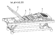
次に、図20及び図21に示す基準パターンに沿って背ボトム2及び膝ボトム5が上げ動作又は下げ動作する態様について説明する。図8乃至図13は、背上げ動作の場合のベッドの変化を示す。なお、この図8乃至図13は、背ボトム2、腰ボトム4、膝ボトム5及び足ボトム7のみを図示し、その他の湾曲部等は図示を省略している。図20の座標(0,0)において、ベッドは図8に示すように水平状態にある。次に、この座標(0,0)から、座標(0,25)に移動する。そうすると、図9に示すように、背ボトム2はそのままで、膝ボトム5が持ち上がる。次に、座標(0,25)から座標(40,25)に移動する。そうすると、図10に示すように、膝角度βは一定(25°)のままで、背角度αが40°まで立ち上がる。
【0062】
その後、座標(40,25)から座標(47,15)に移動する。つまり、背角度αは上昇する一方、膝角度βは小さくなる。そうすると、図11に示すように、背ボトム2及び膝ボトム5はいずれも中間の状態になる。
【0063】
次に、座標(47,15)から座標(60,15)に移動する。つまり、膝角度βは一定のままに、背角度αを更に立ち上げる。これにより、図12に示す状態になる。
【0064】
その後、座標(60,15)から座標(75,0)に移動する。つまり、膝角度βを下げると共に、背角度αを更に立ち上げ、図13に示すように、最終目標の座標(75,0)に至る。
【0065】
このようなパターンで、図8に示す水平の状態から、図13に示すように背ボトム2が75°に立ち上がった状態まで変化する。
【0066】
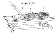
また、背ボトム2の下げ動作においては、ベッドは図13乃至図18に示す態様でその形態が変化する。つまり、図21に示す座標(75,0)から、座標(64,10)に移動する。そうすると、図14に示すように、膝ボトム5が上がると共に、背ボトム2が下がる。
【0067】
次に、座標(64,10)から座標(50,10)に移動する。そうすると、図15に示すように、膝ボトム5の位置は変化せず、背ボトム2のみが下がる。
【0068】
次に、座標(50,10)から座標(40,25)に移動する。そうすると、図16に示すように、背ボトム2が更に下がると共に、膝ボトム5が上昇する。
【0069】
次に、座標(40,25)から座標(19,25)に移動する。そうすると、図17に示すように、膝ボトム5の位置は変化せず、背ボトム2のみが更に下がる。
【0070】
次に、座標(19,25)から座標(0,10)に移動する。そうすると、図18に示すように、膝ボトム5がβ=10°まで下がり、背ボトム2は水平に戻る。
【0071】
次に、座標(0,10)から座標(0,0)に移動する。これにより、ベッドは図8に示す水平状態に戻る。
【0072】
本実施形態においては、背上げ動作の開始スイッチ又は背下げ動作の開始スイッチを1回押す(押し続ける)だけで、背ボトム2の動きと膝ボトム5の動きとを相互に関連づけてずれ及び圧迫感がないように予め求めた最適のパターンに従って、背ボトム2及び膝ボトム5が移動していくので、その動作には、介護者(操作者)の主観が入ることがない。従って、介護者の主観によらず、また介護者が変わった場合でも、ベッドは常に予め求められた最適のパターンで移動するので、ベッド上に横たわる患者は、背上げ操作又は背下げ操作において、ベッド上でのずれが生じることが確実に回避される。また、この上半身を起こす作業及び寝かせる作業のいずれにおいても、患者に圧迫感を与えることがない。そして、患者には、筋肉と皮膚との間にずれを生じることがなく、筋肉から皮膚に向かう細い血管が引き延ばされて血管の閉塞又は血行障害を起こして皮膚に障害が発生するというようなことが防止される。なお、本実施形態においては、固定された腰ボトム4が設けられているので、背上げ操作及び背下げ操作に際し、患者の腰が安定する。
【0073】
図20及び図21に示すパターンは、背上げ動作及び背下げ動作において、横たわる患者のズレがなく、また、患者に圧迫感を与えないパターンとして、推奨されるパターンである。
【0074】
図20に示す背上げパターンにおいて、(α、β)が、先ず、(0,0)から(0,25)に移行するのは、背上げ当初(背角度が0°から10°)において、身体のずれが大きいため、背を上げる前に、膝を上げておくことにより、このずれを抑制するためである。また、(0,25)から(40,25)に移行する期間は、ずれを抑制したまま、背を上げている状態であり、背ボトムと膝ボトムとの間の角度がある程度開いているため、圧迫感は生じない。次に、(40,25)から(47,15)に移行する期間は、背角度αが40°になると、背ボトム2がかなり立ち上がってくるので、圧迫感を感じ始める角度であり、このため、背角度αを更に大きくするときに、膝を下げて、圧迫感を感じないようにしている。この場合に、背ボトムと膝ボトムとのなす角度は大きく変化しないので、ずれは生じない。
【0075】
更に、(47,15)から(60,15)の期間は、膝角度βが一定で背角度αのみが高くなっていく期間である。このため、若干圧迫感が増す。一方、次の(60,15)から(75,0)までの期間は、膝を下げつつ背を上げて最終到達点に至る期間であり、膝を下げているため、前の期間での圧迫感を逃がすことができる。本実施形態では、背角度αと膝角度βを同時に最終到達点(75,0)に到達させることが重要であり、少なくとも背角度αが上昇している間は、膝角度βが0にならないようにすることが必要である。このように、背上げと膝下げとを同時に終了することにより、又は少なくとも背上げが終了した後膝下げが終了するようにすることにより、圧迫感が残留せず、終了後の快適性を向上させることができる。従って、(40,25)から(47,15)に移行する期間で圧迫感を抑制するために膝を下げる必要があり、(60,15)から(75,0)までの期間で背と膝とが同時に最終到達点に移行する必要があるために、(47,15)から(60,15)の期間で、背のみを上げることが必要となる。
【0076】
なお、最終到達点を(75,0)としているが、これは患者がベッドの端に座り(端座位)、車椅子に移る際には、膝角度βは0°であることが好ましい。このように、患者が車椅子に移りやすくして、室内又は室外を移動する機会を増やすことにより、患者のQOL(Quality of Life)を向上させることができる。一方、患者の上半身をベッド上で起こして、体圧が患者の背中及び臀部にかかるのを緩和する操作のためには、膝角度βが10°の近傍まで下がった状態で背上げ動作を停止することが好ましい。このような角度において、安楽な姿勢をとることができる。なお、この場合も、患者の重心をしっかり臀部から下半身に移すためには、(75,0)まで背を上げた方がよい。
【0077】
また、図21に示す背下げパターンにおいて、(75,0)から(64,10)まで移行する期間は、背を下げるときに、同時に膝を上げている。背下げ当初(αが75°から60°)の期間においては、体重が臀部から下半身に集中しているため、背を下げても身体が足側に止まろうとするので、身体のずれが大きくなる。このため、背を下げるときに、同時に膝を上げることにより、体重を上半身に移し、これにより、ずれを抑制している。また、(64,10)から(50,10)に移行する期間は、膝上げを継続すると、体重が過剰に上半身に移るため、腰部に圧迫感が生じる。このため、背ボトムと膝ボトムとの間の角度を開かせるために、膝上げを停止する。
【0078】
更に、(50,10)から(40,25)に移る期間は、圧迫感を感じさせない角度まで開いた後、更に膝を上げて、体重を完全に背ボトム2に移すものである。その後、(40,25)から(19,25)までは、膝角度βを一定にして背を下げてくる。この期間は、膝角度が最大値まで達しているので、身体のずれが生じることなく、背を下げることができる。但し、この期間において、膝も下げてしまうと、体重が再度下半身に移り、ずれを生じてしまうため、膝角度βは一定にする必要がある。
【0079】
その後、(19,25)から(0,10)までの期間は、背角度αが25°まで下がっているので、膝を下げても引きずられないため、背を下げると共に、膝を下げ始める。最後に、(0,10)から(0,0)の期間は、身体が完全に落ち着いた状態で、膝を水平に戻す期間である。
【0080】
なお、上記実施形態においては、前記α0は75°、β0は0°である。最適パターンの目的によっては、β0は必ずしも0°ではなく、例えば、10°程度とし、多少持ち上がった状態としてもよい。また、上記実施形態においては、前記上げパターンを構成する座標点は、(0,0)、(0、25)、(40、25)、(47、15)、(60、15)、(75、0)であり、前記下げパターンを構成する座標点は、(75、0)、(64、10)、(50、10)、(40、25)、(19、25)、(0,10)、(0,0)であったが、この最適パターンを構成する角度は若干相違していても、同様の効果を得ることができる。即ち、上記座標点の各角度が、±3°以内の差であれば、最適な状態で背上げ操作及び背下げ操作を行うことができる。従って、前記上げパターンを構成する座標点は、(0,0)、(0、25±3)、(40±3、25±3)、(47±3、15±3)、(60±3、15±3)、(75±3、0)であり、前記下げパターンを構成する座標点は、(75±3、0)、(64±3、10±3)、(50±3、10±3)、(40±3、25±3)、(19±3、25±3)、(0,10±3)、(0,0)となる。
【0081】
上述の如くして、背上げ動作及び背下げ動作について最適のパターンを求め、これを制御部61の記憶部81に格納しておき、このパターンに基づいて背ボトム2及び膝ボトム5が動作するようにすることにより、開始スイッチを1回押す(押し続ける)だけで、操作者に拘わらず、常に最適のパターンで、背ボトム2及び膝ボトム5を動かすことができる。この最適パターンは、前述の如く、ROMに記憶させて記憶部81に設定しても良いし、RAMに記憶させても良い。
【0082】
上述の最適パターンは、特定の条件を設定して求めたものであるが、この最適パターンはベッド構造の相違、条件の変更又は目的の修正に応じて、適時更新されるべきものである。例えば、図20,図21に示すパターンは、図1乃至図18に示すベッド構造の場合に好ましいパターンである。つまり、背ボトム2,背湾曲部3,腰ボトム4、膝ボトム5,膝湾曲部6及び足ボトム7を有する電動ベッドの場合に、図20,図21のパターンがずれ及び圧迫感を防止するために、好ましいパターンである。しかし、本発明は、背湾曲部及び膝湾曲部を有しないような電動ベッド、腰ボトム又は足ボトムを有しないような電動ベッド、又は背ボトムと腰ボトム又は膝ボトムとの間に、第2の背ボトムがあり、背ボトムが立ち上がるとそれにつれて第2の背ボトムも同一の方向に回動するような電動ベッド等、種々の電動ベッドに適用することができる。これらの場合に、ずれ及び圧迫感を防止するために最適のパターンは、図20及び図21に示すものとは異なる場合が多く、夫々のベッド構造に応じて、この最適パターンを求めればよい。
【0083】
この場合に、ROMを使用する場合は、このROMを取り替えることにより、新しいパターンを記憶部81に設定することができ、RAMを使用する場合は、RAMのデータを外部から書き換えることにより、新しいパターンを記憶部81に設定することができる。
【0084】
【発明の効果】
以上詳述したように、本発明によれば、背ボトムを起き上げるとき、及び背ボトムを寝かせるときに、操作者である介護者の主観に拘わらず、また、操作開始時に背ボトム又は膝ボトムが任意の位置にあっても、常に最適のパターンで背ボトム及び膝ボトムを動作させることができ、これにより、確実に、被介護者がベッド上でずれてしまうことを防止し、被介護者に腹部及び胸部の圧迫感を与えることを防止することができ、被介護者及び介護者の負担を軽減することができる。
【図面の簡単な説明】
【図1】本発明の実施形態に係る電動ベッドを示す斜視図である。
【図2】この電動ベッドの背ボトム、膝ボトム及び足ボトムと、それらの間の湾曲部とを示す平面図である。
【図3】同じくその正面図である。
【図4】背ボトムが水平の場合の背上げ装置を示す正面図である。
【図5】背ボトムを上げた場合の背上げ装置を示す正面図である。
【図6】膝ボトムが水平の場合の膝上げ装置を示す正面図である。
【図7】膝ボトムを上げた場合の膝上げ装置を示す正面図である。
【図8】電動ベッドの動作を示し、座標(α、β)が(0,0)の場合の斜視図である。
【図9】電動ベッドの動作を示し、座標(α、β)が(0,25)の場合の斜視図である。
【図10】電動ベッドの動作を示し、座標(α、β)が(40,25)の場合の斜視図である。
【図11】電動ベッドの動作を示し、座標(α、β)が(47,15)の場合の斜視図である。
【図12】電動ベッドの動作を示し、座標(α、β)が(60,15)の場合の斜視図である。
【図13】電動ベッドの動作を示し、座標(α、β)が(75,0)の場合の斜視図である。
【図14】電動ベッドの動作を示し、座標(α、β)が(64,10)の場合の斜視図である。
【図15】電動ベッドの動作を示し、座標(α、β)が(50,10)の場合の斜視図である。
【図16】電動ベッドの動作を示し、座標(α、β)が(40,25)の場合の斜視図である。
【図17】電動ベッドの動作を示し、座標(α、β)が(19,25)の場合の斜視図である。
【図18】電動ベッドの動作を示し、座標(α、β)が(0,10)の場合の斜視図である。
【図19】本発明の実施形態の制御装置を示すブロック図である。
【図20】背上げパターンを示すグラフ図である。
【図21】背下げパターンを示すグラフ図である。
【図22】背上げ操作時の動作態様を示すグラフ図である。
【図23】背下げ操作時の動作態様を示すグラフ図である。
【図24】制御部のフローチャート図である。
【符号の説明】
1:電動ベッド
2:背ボトム
3:背湾曲部
4:腰ボトム
5:膝ボトム
6:膝湾曲部
7:足ボトム
11:操作ボックス
20:背上げ装置
21:支持棒
23〜26、43:リンク
28、45:アクチュエータ
40:膝上げ装置
41,42:支持部
62:制御部
68〜70:モータ
71〜73:センサ
81:記憶部
82:演算部[0001]
BACKGROUND OF THE INVENTION
The present invention relates to an electric bed capable of electrically raising the back portion of a bed in a care bed or the like, and in particular, in a state where a care receiver such as a patient lies down, the care receiver is displaced or has a feeling of pressure. The present invention relates to an electric bed that can raise a back portion without feeling, a control method thereof, and a control device.
[0002]
[Prior art]
In an aging society, the number of bedridden patients is increasing, but it is necessary to wake up the upper body of the patient on a bed for medical purposes, eating meals, watching TV or reading. Therefore, an electric bed has been developed that can raise and lower the back bottom and knee bottom of the bed electrically. However, when the electric bed is raised and lowered, the patient's body is displaced or force is applied. As a result, a shift occurs between the muscle and the skin, and a thin blood vessel extending from the muscle to the skin is stretched to easily cause occlusion of the blood vessel or blood circulation disorder, and the skin is damaged. In addition, returning the body of a bedridden patient whose position has been shifted by raising and lowering the back to the original position by the caregiver is extremely burdensome for the caregiver because the patient cannot move by himself / herself. .
[0003]
Moreover, even if it is not bedridden, when it moves from a bed to a wheelchair, by raising the upper body of the patient on the bed, it becomes easy to take a sitting posture on the bed, and it becomes easy to move to the wheelchair as it is. Also in this case, it is preferable that the body does not slip or force is applied when the patient's upper body is raised.
[0004]
Therefore, in the electric bed that can raise the back and knees, change the timing of the electric back-lifting operation and knee-lifting operation, and make sure that the angle between the back bottom and the knee bottom is not narrowed more than necessary. A back knee interlocking control method using an easy-to-use bed is disclosed (Patent Document 1: Japanese Patent Laid-Open No. 2001-37820).
[0005]
[Patent Document 1]
JP 2001-37820 A
[0006]
[Problems to be solved by the invention]
However, the conventional technology described in this publication can control the back-lifting and knee-lifting operations independently, but basically, the operations of back-lifting and knee-lifting are performed separately. It is. That is, the operator (caregiver) performs the operation of starting and stopping the back raising and the operation of starting and stopping the knee raising. For this reason, the knee bottom is raised by 20-30 ° after the knee bottom is raised so that the patient is not displaced by raising the back, but the operation of raising the back bottom is performed. Even if the caregiver performs such an operation, it is not always possible to sufficiently prevent the shift when raising the back as long as it is a subjective operation of the caregiver. Further, it has not been possible to reliably prevent the patient from feeling pressure in the back raising operation and the back lowering operation.
[0007]
The present invention has been made in view of such a problem, and when raising the back bottom (back raising operation) and laying the back bottom (back lowering operation), the caregiver who is the operator has the subjectivity. Regardless of this, it is possible to reliably prevent the cared person from slipping on the bed, and to prevent the cared person from feeling pressure on the abdomen and chest during this operation. It is another object of the present invention to provide an electric bed, a control method thereof, and a control device that can reduce the burden on a caregiver.
[0008]
[Means for Solving the Problems]
The electric bed according to the present invention includes a back bottom, a knee bottom, a first drive unit that swings the back bottom up and down, a second drive unit that swings the knee bottom up and down, and a horizontal state of the back bottom. When the (α, β) coordinate plane is assumed by the back angle α, which is the lifting angle from the knee, and the knee angle β, which is the lifting angle from the horizontal state of the knee bottom, each bottom in the (α, β) coordinate plane The coordinate point (0, 0) in a horizontal state and the coordinate point (α 0 , Β 0 ) With a line segment that passes through multiple coordinate points between them As Pre-set so that the person lying on the bed is less likely to slip and feel tight. Met Reference pattern The set And The reference pattern is a process in which the knee angle β increases once and then decreases in the process of increasing the back angle α, A control unit that controls the first drive unit and the second drive unit so that α and β change along a reference pattern, and the control unit sets the (α, β) coordinate plane to a plurality of areas. For each area, the coordinates (α, β) when the coordinates (α, β) of the back angle α and knee angle β are located at positions not on the reference pattern in the area are used as the reference. A storage unit that stores an operation mode for operating the back bottom and the knee bottom to match the pattern, and when the coordinates (α, β) are not located on the reference pattern, the coordinates (α , Β), and an arithmetic unit that controls the first drive unit and the second drive unit based on the operation mode of the area.
[0009]
The electric bed control method according to the present invention includes a back bottom, a knee bottom, a first drive unit that swings the back bottom up and down, and a second drive unit that swings the knee bottom up and down. In the control method of the electric bed, when (α, β) coordinate plane is assumed by the back angle α that is the lifting angle from the horizontal state of the back bottom and the knee angle β that is the lifting angle from the horizontal state of the knee bottom Further, in the (α, β) coordinate plane, the coordinate point (0, 0) where each bottom is horizontal and the coordinate point (α 0 , Β 0 ) With a line segment that passes through multiple coordinate points between them As Pre-set so that the person lying on the bed is less likely to slip and feel tight. Met Reference pattern The set And The reference pattern is a process in which the knee angle β increases once and then decreases in the process of increasing the back angle α, The (α, β) coordinate plane is divided into a plurality of areas, and for each area, the coordinates (α, β) of the back angle α and the knee angle β are located at positions not on the reference pattern in the area. In order to match the coordinates (α, β) on the reference pattern, the operation mode of operating the back bottom and the knee bottom is stored, and the coordinates (α, β) are stored on the reference pattern. When not located, so as to determine in which area the coordinates (α, β) are, and position the coordinates (α, β) on the reference pattern according to the operation mode of the area, The first driving unit and the second driving unit are controlled.
[0010]
Furthermore, the control device for the electric bed according to the present invention includes a back bottom, a knee bottom, a first drive unit that swings the back bottom up and down, and a second drive unit that swings the knee bottom up and down. In the control device for controlling the electric bed, the (α, β) coordinate plane is defined by a back angle α which is a lifting angle from the horizontal state of the back bottom and a knee angle β which is a lifting angle from the horizontal state of the knee bottom. Assuming that, on the (α, β) coordinate plane, the coordinate point (0, 0) where each bottom is horizontal and the coordinate point (α) where the back bottom rises 0 , Β 0 ) With a line segment that passes through multiple coordinate points between them As Pre-set so that the person lying on the bed is less likely to slip and feel tight. Met Reference pattern The set And The reference pattern is a process in which the knee angle β increases once and then decreases in the process of increasing the back angle α, The reference pattern and the (α, β) coordinate plane are divided into a plurality of areas, and for each area, the coordinates (α, β) of the back angle α and knee angle β are not on the reference pattern in the area. A storage unit for storing an operation mode of operating the back bottom and the knee bottom to match the coordinates (α, β) on the reference pattern when positioned at the position, and the coordinates (α, β) Is not located on the reference pattern, it is determined in which area the coordinates (α, β) are, and the first drive unit and the second drive unit based on the operation mode of the area And an arithmetic unit for controlling the operation.
[0011]
In the electric bed, as the pattern, a raising pattern for raising the back bottom from a horizontal state and a lowering pattern for lowering the back bottom from a raised state to a horizontal state are individually provided. preferable.
[0012]
Further, for example, an operation box for inputting a start signal for selecting one of a back raising operation for raising the back bottom from a horizontal state and a back lowering operation for lowering the back bottom to a horizontal state to start the operation of the control unit. The operation box includes a first switch for instructing the start of the back raising operation, and a second switch for instructing the start of the back-lowering operation, and the computing unit includes the first switch. Is determined to have been instructed to start a back raising operation, and when the first switch is turned off and the second switch is turned on, it is determined to have been instructed to start a back lowering operation, It is preferable to output a stop request when both the first switch and the second switch are off.
[0013]
In the electric bed of the present invention, the electric bed has a back bending portion that connects the back bottom and the knee bottom so as to be bent, and the α 0 Is 75 °, β 0 Is 0 °, and the coordinate points constituting the raised pattern are (0, 0), (0, 25 ± 3), (40 ± 3, 25 ± 3), (47 ± 3, 15 ± 3), (60 ± 3, 15 ± 3), (75 ± 3, 0), and the coordinate points constituting the lowered pattern are (75 ± 3, 0), (64 ± 3, 10 ± 3), (50 It is preferable that they are ± 3, 10 ± 3), (40 ± 3, 25 ± 3), (19 ± 3, 25 ± 3), (0, 10 ± 3), (0, 0).
[0014]
Further, a fixed waist bottom is connected between the back curved portion and the knee bottom, and the foot bottom is connected to the opposite side of the back bottom of the knee bottom via a bendable knee curved portion. The foot bottom is connected to the knee bottom by a link mechanism and can be configured to move in conjunction with the foot bottom.
[0015]
In addition, the electric bed control method includes a pattern for raising the back bottom from the horizontal state and a pattern for lowering the back bottom from the raised state to the horizontal state as the patterns. Preferably it is.
[0016]
In the electric bed control method of the present invention, the back bottom and the knee bottom are connected to each other so as to be bendable by a back bending portion, and the α 0 Is 75 °, β 0 Is 0 °, and the coordinate points constituting the raised pattern are (0, 0), (0, 25 ± 3), (40 ± 3, 25 ± 3), (47 ± 3, 15 ± 3), (60 ± 3, 15 ± 3), (75 ± 3, 0), and the coordinate points constituting the lowered pattern are (75 ± 3, 0), (64 ± 3, 10 ± 3), (50 It is preferable that they are ± 3, 10 ± 3), (40 ± 3, 25 ± 3), (19 ± 3, 25 ± 3), (0, 10 ± 3), (0, 0).
[0017]
Further, a fixed waist bottom is connected between the back curve portion and the knee bottom, and the foot bottom is connected to the knee bottom on the opposite side of the back bottom via a bendable knee curve portion. The foot bottom is preferably connected to the knee bottom by a link mechanism and moves in conjunction with the foot bottom.
[0018]
In the electric bed control device of the present invention, as the pattern, a raising pattern for raising the back bottom from the horizontal state and a lowering pattern for lowering the back bottom from the raised state to the horizontal state are individually provided. It is preferable that
[0019]
In addition, there is an operation box for inputting a start signal for starting the operation of the control unit by selecting either a back raising operation for raising the back bottom from a horizontal state or a back lowering operation for lowering the back bottom to a horizontal state. The operation box includes a first switch for instructing the start of the back raising operation and a second switch for instructing the start of the back lowering operation, and the arithmetic unit is configured to turn on the first switch. When the first switch is turned on, it is determined that the start of the back raising operation is instructed, and when the first switch is turned off and the second switch is turned on, it is determined that the start of the back lifting operation is instructed. It is preferable to output a stop request when both the switch and the second switch are off.
[0020]
In the control device for the electric bed of the present invention, the back bottom and the knee bottom are connected to each other so as to be bendable by a back bending portion, and the α 0 Is 75 °, β 0 Is 0 °, and the coordinate points constituting the raised pattern are (0, 0), (0, 25 ± 3), (40 ± 3, 25 ± 3), (47 ± 3, 15 ± 3), (60 ± 3, 15 ± 3), (75 ± 3, 0), and the coordinate points constituting the lowered pattern are (75 ± 3, 0), (64 ± 3, 10 ± 3), (50 It is preferable that they are ± 3, 10 ± 3), (40 ± 3, 25 ± 3), (19 ± 3, 25 ± 3), (0, 10 ± 3), (0, 0).
[0021]
Further, a fixed waist bottom is connected between the back curved portion and the knee bottom, and the foot bottom is connected to the opposite side of the back bottom of the knee bottom via a bendable knee curved portion. The foot bottom is preferably connected to the knee bottom by a link mechanism and moves in conjunction with the foot bottom.
[0022]
DETAILED DESCRIPTION OF THE INVENTION
Hereinafter, embodiments of the present invention will be described in detail with reference to the accompanying drawings. FIG. 1 is a perspective view showing an electric bed according to an embodiment of the present invention, FIG. 2 is a plan view showing a back bottom, a knee bottom and a foot bottom of the electric bed, and a curved portion therebetween, and FIG. Similarly, FIG. 4 is a front view showing the back raising device when the back bottom is horizontal, FIG. 5 is a front view showing the back raising device when the back bottom is raised, and FIG. 6 is when the knee bottom is horizontal. 7 is a front view showing the knee-lifting device when the knee bottom is raised, and FIGS. 8 to 18 are perspective views showing the operation of the electric bed.
[0023]
As shown in FIGS. 1 to 3, the electric bed 1 of the present embodiment includes a
[0024]
The electric bed 1 is configured such that a frame that supports the above-described back bottom 2 and the like is moved up and down by an actuator (none of which is shown), whereby the bed height can be adjusted. It is like that.
[0025]
As shown in FIGS. 2 and 3, below the
[0026]
As shown in FIGS. 4 and 5, in the
[0027]
As shown in FIGS. 6 and 7, in the
[0028]
In the present specification, the fixed fulcrum means that the position of the fulcrum is fixed without moving, and the link itself pivotally supported by the fixed fulcrum is rotatable with respect to the fixed fulcrum. The fixed fulcrum is fixed to the frame that supports the
[0029]
The
[0030]
FIG. 19 is a block diagram showing a configuration of the
[0031]
A pulse width modulation (PWM) signal is input from the
[0032]
The
[0033]
20 and 21 show the back-up and back-down reference patterns stored in the
[0034]
The reference pattern is expressed by a coordinate system (α, β) composed of a back angle α and a knee angle β. That is, for the raising pattern for raising the
[0035]
Thus, when the back bottom and the knee bottom are raised or lowered according to the pattern shown in FIG. 20 or FIG. 21 from the horizontal position of (0, 0) or the back raised position of (75, 0). Instead, the back bottom may be raised or lowered from the state where the back bottom or the knee bottom has already risen. FIGS. 22 and 23 show that when the back bottom and knee bottom are in a position deviating from the patterns shown in FIG. 20 and FIG. It is a figure which shows the operation | movement aspect to lower.
[0036]
In the aspect at the time of the back raising operation shown in FIG. 22, the (α, β) coordinate system is divided into four areas 1 to 4 shown in FIG. The movement mode is determined. This movement mode is a mode in which the back bottom and the knee bottom are moved according to the area where the back bottom (back angle α) and the knee bottom (knee angle β) exist when attempting to raise the back. . That is, the range of each area and the movement mode are as follows.
[0037]
(1) Area 1
Range: 0 ≦ α ≦ 40, 0 ≦ β ≦ 25
Aspect: The back angle α remains constant, and only the knee angle β is raised.
(2)
Range: 40 ≦ α ≦ 60, 0 ≦ β ≦ 15
Aspect: The knee angle β remains constant, and the back angle α is increased.
(3)
Range: 60 ≦ α ≦ 75, 0 ≦ β ≦ 15 and 40 ≦ α ≦ 75, 15 ≦ β ≦ 25
Aspect: The back angle α is increased and the knee angle β is decreased.
(4)
Range: 25 ≦ β
Aspect: The knee angle β is decreased while the back angle α remains constant.
[0038]
When the back angle α is 75 ° or more, the present embodiment does not operate.
[0039]
23, the (α, β) coordinate system is divided into five areas,
[0040]
(5)
Range: 50 ≦ α ≦ 75, 0 ≦ β ≦ 25 and 20 ≦ α ≦ 50, 10 ≦ β ≦ 25
Aspect: The back angle α is decreased and the knee angle β is increased.
(6)
Range: 20 ≦ α ≦ 50, 0 ≦ β ≦ 10
Aspect: The knee angle β is increased while the back angle α remains constant.
(7)
Range: 0 ≦ α ≦ 20, 0 ≦ β ≦ 10
Aspect: The knee angle β remains constant, and the back angle α is increased.
(8) Area 8
Range: 0 ≦ α ≦ 20, 10 ≦ β ≦ 25
Aspect: The back angle α is lowered and the knee angle β is also lowered.
(9)
Range: 25 ≦ β
Aspect: The knee angle β is decreased while the back angle α remains constant.
[0041]
When the back angle α is 75 ° or more, the present embodiment does not operate, and only the back bottom is lowered by individual operations.
[0042]
Next, the operation of the electric bed configured as described above will be described. First, operations of the
[0043]
On the other hand, when the
[0044]
In the
[0045]
Such a back raising operation and a back lowering operation proceed simultaneously in conjunction with each other, and the
[0046]
The
[0047]
When a signal instructing the start of the back raising operation is input from the
[0048]
Then, the current back angle α and knee angle β are compared with the operation mode of FIG. 22 to determine the operation requests of the
[0049]
When the signal for instructing the back raising operation is input from the
[0050]
The same applies to the case where the back angle α and the knee angle β are in the
[0051]
On the other hand, if the start signal transmitted from the
[0052]
When the signal instructing the back-lowering operation is input from the
[0053]
Furthermore, when the signal input from the
[0054]
In step S6 of FIG. 24, when the back bottom operation request is “stop request”, the
[0055]
On the other hand, if the knee bottom motion request is “stop request” in step S11 of FIG. 24, the
[0056]
Then, returning to step S1 again, this flow is repeated at an appropriate interval, whereby the
[0057]
Note that a signal instructing the start of a back raising operation (back raising operation) or a signal instructing a back lowering operation (back lowering operation) is input from the
[0058]
In the above embodiment, the back angle α formed by the
[0059]
However, the drive control of the
[0060]
Further, the height of the position on the distal end side when the
[0061]
Next, a mode in which the
[0062]
Thereafter, the coordinate (40, 25) is moved to the coordinate (47, 15). That is, the back angle α increases while the knee angle β decreases. Then, as shown in FIG. 11, the
[0063]
Next, the coordinate (47, 15) is moved to the coordinate (60, 15). That is, the back angle α is further raised while the knee angle β remains constant. As a result, the state shown in FIG. 12 is obtained.
[0064]
Thereafter, the coordinate (60, 15) is moved to the coordinate (75, 0). That is, the knee angle β is lowered and the back angle α is further raised to reach the final target coordinates (75, 0) as shown in FIG.
[0065]
In such a pattern, the horizontal state shown in FIG. 8 changes to a state where the
[0066]
Further, in the lowering operation of the
[0067]
Next, the coordinate (64, 10) is moved to the coordinate (50, 10). Then, as shown in FIG. 15, the position of the
[0068]
Next, the coordinate (50, 10) is moved to the coordinate (40, 25). Then, as shown in FIG. 16, the
[0069]
Next, the coordinate (40, 25) is moved to the coordinate (19, 25). Then, as shown in FIG. 17, the position of the
[0070]
Next, the coordinate (19, 25) is moved to the coordinate (0, 10). Then, as shown in FIG. 18, the
[0071]
Next, the coordinate (0, 10) is moved to the coordinate (0, 0). Thereby, the bed returns to the horizontal state shown in FIG.
[0072]
In the present embodiment, the movement of the
[0073]
The patterns shown in FIGS. 20 and 21 are recommended patterns as a pattern in which there is no displacement of the lying patient and does not give the patient a feeling of pressure in the back raising operation and the back lowering operation.
[0074]
In the back raising pattern shown in FIG. 20, (α, β) first shifts from (0, 0) to (0, 25) at the beginning of back raising (back angle is 0 ° to 10 °). This is because the shift of the body is large, so that the shift is suppressed by raising the knee before raising the back. Further, the period of transition from (0, 25) to (40, 25) is a state where the back is raised while suppressing the deviation, and the angle between the back bottom and the knee bottom is somewhat open. The feeling of oppression does not occur. Next, the period of transition from (40, 25) to (47, 15) is the angle at which the
[0075]
Further, the period from (47,15) to (60,15) is a period in which the knee angle β is constant and only the back angle α is increased. For this reason, a feeling of pressure increases a little. On the other hand, the next period from (60,15) to (75,0) is a period until the final point is reached while raising the back while lowering the knee. You can escape the feeling. In this embodiment, it is important that the back angle α and the knee angle β reach the final arrival point (75, 0) at the same time, and the knee angle β does not become zero at least while the back angle α is rising. It is necessary to do so. In this way, by finishing the back-up and knee-down at the same time, or at least after the back-up is finished, the knee-down is finished, so that the feeling of pressure does not remain and the comfort after the end is improved. Can be made. Therefore, it is necessary to lower the knee to suppress the feeling of pressure during the period from (40, 25) to (47, 15), and the back and knee during the period from (60, 15) to (75, 0). Since it is necessary to shift to the final destination at the same time, it is necessary to raise only the back during the period from (47, 15) to (60, 15).
[0076]
In addition, although the final arrival point is (75, 0), when the patient sits on the end of the bed (end sitting position) and moves to the wheelchair, the knee angle β is preferably 0 °. Thus, the patient's QOL (Quality of Life) can be improved by making it easier for the patient to move to the wheelchair and increasing the opportunity to move indoors or outdoors. On the other hand, to raise the patient's upper body on the bed and relieve the body pressure from being applied to the patient's back and buttocks, the back-up operation is stopped with the knee angle β lowered to around 10 °. It is preferable to do. At such an angle, a comfortable posture can be taken. In this case as well, it is better to raise the back to (75, 0) in order to firmly move the patient's center of gravity from the buttocks to the lower body.
[0077]
In the back-lowering pattern shown in FIG. 21, during the period from (75, 0) to (64, 10), the knees are raised simultaneously when lowering the back. In the period when the back is initially lowered (α is 75 ° to 60 °), the weight is concentrated from the buttocks to the lower half of the body. . For this reason, when lowering the back, by simultaneously raising the knee, the weight is transferred to the upper body, thereby suppressing the deviation. In addition, during the period of transition from (64, 10) to (50, 10), if the knee-lifting is continued, the body weight moves excessively to the upper body, so that a sense of pressure is generated at the waist. For this reason, knee lift is stopped in order to open the angle between the back bottom and the knee bottom.
[0078]
Further, in the period from (50, 10) to (40, 25), after opening to an angle that does not cause a feeling of pressure, the knees are further raised, and the weight is completely transferred to the
[0079]
Thereafter, during the period from (19, 25) to (0, 10), since the back angle α is lowered to 25 °, it cannot be dragged even if the knee is lowered, so the back is lowered and the knee is started to be lowered. Finally, the period from (0, 10) to (0, 0) is a period in which the knee is returned to the horizontal position while the body is completely calm.
[0080]
In the above embodiment, the α 0 Is 75 °, β 0 Is 0 °. Depending on the purpose of the optimal pattern, β 0 Is not necessarily 0 °, but may be about 10 °, for example, and may be raised slightly. In the above embodiment, the coordinate points constituting the raised pattern are (0, 0), (0, 25), (40, 25), (47, 15), (60, 15), (75 , 0), and the coordinate points constituting the lowered pattern are (75, 0), (64, 10), (50, 10), (40, 25), (19, 25), (0, 10). ), (0, 0), the same effect can be obtained even if the angles constituting the optimum pattern are slightly different. That is, if each angle of the coordinate points is within ± 3 °, the back raising operation and the back lowering operation can be performed in an optimum state. Therefore, the coordinate points constituting the raised pattern are (0, 0), (0, 25 ± 3), (40 ± 3, 25 ± 3), (47 ± 3, 15 ± 3), (60 ± 3). , 15 ± 3), (75 ± 3, 0), and the coordinate points constituting the lowered pattern are (75 ± 3, 0), (64 ± 3, 10 ± 3), (50 ± 3, 10 ± 3), (40 ± 3, 25 ± 3), (19 ± 3, 25 ± 3), (0,10 ± 3), (0,0).
[0081]
As described above, an optimum pattern for the back raising operation and the back lowering operation is obtained and stored in the
[0082]
The above-mentioned optimum pattern is obtained by setting a specific condition, and this optimum pattern should be updated in a timely manner according to the difference in bed structure, change in condition, or modification of purpose. For example, the patterns shown in FIGS. 20 and 21 are preferable patterns in the case of the bed structure shown in FIGS. That is, in the case of the electric bed having the
[0083]
In this case, if a ROM is used, a new pattern can be set in the
[0084]
【The invention's effect】
As described above in detail, according to the present invention, when raising the back bottom and putting the back bottom to sleep, regardless of the subjectivity of the caregiver who is the operator, The back bottom and knee bottom can always be operated in an optimal pattern even when the is in an arbitrary position, thereby reliably preventing the cared person from slipping on the bed. It is possible to prevent the abdomen and chest from being compressed, and the burden on the care recipient and the caregiver can be reduced.
[Brief description of the drawings]
FIG. 1 is a perspective view showing an electric bed according to an embodiment of the present invention.
FIG. 2 is a plan view showing a back bottom, a knee bottom, and a foot bottom of the electric bed, and a curved portion therebetween.
FIG. 3 is a front view of the same.
FIG. 4 is a front view showing the back raising device when the back bottom is horizontal.
FIG. 5 is a front view showing the back raising device when the back bottom is raised.
FIG. 6 is a front view showing the knee lifting device when the knee bottom is horizontal.
FIG. 7 is a front view showing the knee raising device when the knee bottom is raised.
FIG. 8 is a perspective view showing the operation of the electric bed when coordinates (α, β) are (0, 0).
FIG. 9 is a perspective view showing the operation of the electric bed when the coordinates (α, β) are (0, 25).
FIG. 10 is a perspective view showing the operation of the electric bed when the coordinates (α, β) are (40, 25).
FIG. 11 is a perspective view showing the operation of the electric bed when the coordinates (α, β) are (47, 15).
FIG. 12 is a perspective view showing the operation of the electric bed when the coordinates (α, β) are (60, 15).
FIG. 13 is a perspective view showing the operation of the electric bed when the coordinates (α, β) are (75, 0).
FIG. 14 is a perspective view showing the operation of the electric bed and in the case where the coordinates (α, β) are (64, 10).
FIG. 15 is a perspective view showing the operation of the electric bed when the coordinates (α, β) are (50, 10).
FIG. 16 is a perspective view showing the operation of the electric bed when the coordinates (α, β) are (40, 25).
FIG. 17 is a perspective view showing the operation of the electric bed when coordinates (α, β) are (19, 25).
FIG. 18 is a perspective view showing the operation of the electric bed when coordinates (α, β) are (0, 10).
FIG. 19 is a block diagram illustrating a control device according to an embodiment of the present invention.
FIG. 20 is a graph showing a back-up pattern.
FIG. 21 is a graph showing a back-lowering pattern.
FIG. 22 is a graph showing an operation mode during a back raising operation.
FIG. 23 is a graph showing an operation mode during a back-lowering operation.
FIG. 24 is a flowchart of the control unit.
[Explanation of symbols]
1: Electric bed
2: Back bottom
3: Back curve
4: Waist bottom
5: Knee bottom
6: Knee bending part
7: Foot bottom
11: Operation box
20: Back raising device
21: Support rod
23-26, 43: Link
28, 45: Actuator
40: Knee raising device
41, 42: support part
62: Control unit
68-70: Motor
71-73: Sensor
81: Storage unit
82: Calculation unit
Claims (14)
Priority Applications (6)
| Application Number | Priority Date | Filing Date | Title |
|---|---|---|---|
| JP2002327627A JP4179852B2 (en) | 2002-11-11 | 2002-11-11 | Electric bed, control method and control apparatus therefor |
| US10/689,647 US7058999B2 (en) | 2002-10-24 | 2003-10-22 | Electric bed and control apparatus and control method therefor |
| KR1020030074085A KR100569046B1 (en) | 2002-10-24 | 2003-10-23 | Electric bed and control apparatus and control method therefor |
| TW092129383A TWI225785B (en) | 2002-10-24 | 2003-10-23 | Electric bed and control apparatus and control method therefor |
| EP03024456A EP1413281B1 (en) | 2002-10-24 | 2003-10-23 | Electric bed and control apparatus and control method therefor |
| DE60311381T DE60311381T2 (en) | 2002-10-24 | 2003-10-23 | Electric bed and control device and control method therefor |
Applications Claiming Priority (1)
| Application Number | Priority Date | Filing Date | Title |
|---|---|---|---|
| JP2002327627A JP4179852B2 (en) | 2002-11-11 | 2002-11-11 | Electric bed, control method and control apparatus therefor |
Publications (2)
| Publication Number | Publication Date |
|---|---|
| JP2004159805A JP2004159805A (en) | 2004-06-10 |
| JP4179852B2 true JP4179852B2 (en) | 2008-11-12 |
Family
ID=32806154
Family Applications (1)
| Application Number | Title | Priority Date | Filing Date |
|---|---|---|---|
| JP2002327627A Expired - Fee Related JP4179852B2 (en) | 2002-10-24 | 2002-11-11 | Electric bed, control method and control apparatus therefor |
Country Status (1)
| Country | Link |
|---|---|
| JP (1) | JP4179852B2 (en) |
Cited By (2)
| Publication number | Priority date | Publication date | Assignee | Title |
|---|---|---|---|---|
| JP2019055057A (en) * | 2017-09-21 | 2019-04-11 | 有限会社 和晃 | Electric bed |
| JP2019055058A (en) * | 2017-09-21 | 2019-04-11 | 有限会社 和晃 | Electric bed |
Families Citing this family (8)
| Publication number | Priority date | Publication date | Assignee | Title |
|---|---|---|---|---|
| JP4583740B2 (en) * | 2003-09-16 | 2010-11-17 | 株式会社ミツバ | Drive control device for electric Gatchbed |
| JP4936305B2 (en) * | 2005-12-06 | 2012-05-23 | ドリームベッド株式会社 | Movable bed |
| KR100621349B1 (en) | 2006-05-12 | 2006-09-07 | 주식회사 해피베드 | Patient bed having angle-adjustable devided backrest |
| KR100621350B1 (en) * | 2006-05-12 | 2006-09-07 | 주식회사 해피베드 | Patient bed having operration system for exercise of legs joints |
| KR100661870B1 (en) | 2006-05-12 | 2006-12-27 | 주식회사 해피베드 | Angle-adjustable patient bed with slip-prevention system |
| JP4857156B2 (en) | 2007-03-12 | 2012-01-18 | パラマウントベッド株式会社 | Electric bed and control method thereof |
| KR101007951B1 (en) | 2010-09-29 | 2011-01-14 | 장태복 | Lying type exercising apparatus for strengthening muscle |
| WO2013077288A1 (en) | 2011-11-22 | 2013-05-30 | パラマウントベッド株式会社 | Bed device |
-
2002
- 2002-11-11 JP JP2002327627A patent/JP4179852B2/en not_active Expired - Fee Related
Cited By (2)
| Publication number | Priority date | Publication date | Assignee | Title |
|---|---|---|---|---|
| JP2019055057A (en) * | 2017-09-21 | 2019-04-11 | 有限会社 和晃 | Electric bed |
| JP2019055058A (en) * | 2017-09-21 | 2019-04-11 | 有限会社 和晃 | Electric bed |
Also Published As
| Publication number | Publication date |
|---|---|
| JP2004159805A (en) | 2004-06-10 |
Similar Documents
| Publication | Publication Date | Title |
|---|---|---|
| JP4857156B2 (en) | Electric bed and control method thereof | |
| KR100569046B1 (en) | Electric bed and control apparatus and control method therefor | |
| JP3707555B2 (en) | Electric bed, its control method and control device | |
| EP1354539B1 (en) | Method of adjustment of a base structure for a bed or the like | |
| EP1346669B1 (en) | Method of adjustment of a base structure for a bed or the like | |
| US8068924B2 (en) | Coordinative control method for adjusting the back and knee bottom sections of an adjustable bed, and computer program for implementing same | |
| JP4179852B2 (en) | Electric bed, control method and control apparatus therefor | |
| US10413462B2 (en) | Bed apparatus and bed apparatus control method | |
| EP1346671B1 (en) | Method of adjustment of a base structure for a bed or the like | |
| TWI242430B (en) | Bottom adjusting action-controlled system for a bed or the like | |
| JP2006346311A (en) | Motion control device of electric bed | |
| US6854141B2 (en) | Lifting control method for lying furniture such as a bed | |
| EP1346668A1 (en) | Method of adjustment of a base structure for a bed or the like | |
| KR101224447B1 (en) | Eletrically driven medical bed with tilting function | |
| JP2003135535A (en) | Bottom operation control system for bed | |
| JP6037609B2 (en) | Electric bed and body slip prevention control method | |
| JP2007061361A (en) | Caring bed | |
| JP3862663B2 (en) | Control method for raising and lowering the bottom of a supine table such as a bed | |
| JP2005253805A (en) | Motion control device of electric bed |
Legal Events
| Date | Code | Title | Description |
|---|---|---|---|
| A621 | Written request for application examination |
Free format text: JAPANESE INTERMEDIATE CODE: A621 Effective date: 20050304 |
|
| A711 | Notification of change in applicant |
Free format text: JAPANESE INTERMEDIATE CODE: A711 Effective date: 20060919 |
|
| A521 | Request for written amendment filed |
Free format text: JAPANESE INTERMEDIATE CODE: A821 Effective date: 20060919 |
|
| RD02 | Notification of acceptance of power of attorney |
Free format text: JAPANESE INTERMEDIATE CODE: A7422 Effective date: 20070305 |
|
| A521 | Request for written amendment filed |
Free format text: JAPANESE INTERMEDIATE CODE: A821 Effective date: 20070305 |
|
| A131 | Notification of reasons for refusal |
Free format text: JAPANESE INTERMEDIATE CODE: A131 Effective date: 20071016 |
|
| A521 | Request for written amendment filed |
Free format text: JAPANESE INTERMEDIATE CODE: A523 Effective date: 20071217 |
|
| A131 | Notification of reasons for refusal |
Free format text: JAPANESE INTERMEDIATE CODE: A131 Effective date: 20080122 |
|
| A521 | Request for written amendment filed |
Free format text: JAPANESE INTERMEDIATE CODE: A523 Effective date: 20080321 |
|
| A02 | Decision of refusal |
Free format text: JAPANESE INTERMEDIATE CODE: A02 Effective date: 20080415 |
|
| A521 | Request for written amendment filed |
Free format text: JAPANESE INTERMEDIATE CODE: A523 Effective date: 20080616 |
|
| A911 | Transfer to examiner for re-examination before appeal (zenchi) |
Free format text: JAPANESE INTERMEDIATE CODE: A911 Effective date: 20080729 |
|
| TRDD | Decision of grant or rejection written | ||
| A01 | Written decision to grant a patent or to grant a registration (utility model) |
Free format text: JAPANESE INTERMEDIATE CODE: A01 Effective date: 20080826 |
|
| A01 | Written decision to grant a patent or to grant a registration (utility model) |
Free format text: JAPANESE INTERMEDIATE CODE: A01 |
|
| A61 | First payment of annual fees (during grant procedure) |
Free format text: JAPANESE INTERMEDIATE CODE: A61 Effective date: 20080826 |
|
| R150 | Certificate of patent or registration of utility model |
Ref document number: 4179852 Country of ref document: JP Free format text: JAPANESE INTERMEDIATE CODE: R150 Free format text: JAPANESE INTERMEDIATE CODE: R150 |
|
| FPAY | Renewal fee payment (event date is renewal date of database) |
Free format text: PAYMENT UNTIL: 20110905 Year of fee payment: 3 |
|
| FPAY | Renewal fee payment (event date is renewal date of database) |
Free format text: PAYMENT UNTIL: 20110905 Year of fee payment: 3 |
|
| FPAY | Renewal fee payment (event date is renewal date of database) |
Free format text: PAYMENT UNTIL: 20120905 Year of fee payment: 4 |
|
| R250 | Receipt of annual fees |
Free format text: JAPANESE INTERMEDIATE CODE: R250 |
|
| FPAY | Renewal fee payment (event date is renewal date of database) |
Free format text: PAYMENT UNTIL: 20120905 Year of fee payment: 4 |
|
| FPAY | Renewal fee payment (event date is renewal date of database) |
Free format text: PAYMENT UNTIL: 20130905 Year of fee payment: 5 |
|
| R250 | Receipt of annual fees |
Free format text: JAPANESE INTERMEDIATE CODE: R250 |
|
| R250 | Receipt of annual fees |
Free format text: JAPANESE INTERMEDIATE CODE: R250 |
|
| R250 | Receipt of annual fees |
Free format text: JAPANESE INTERMEDIATE CODE: R250 |
|
| R250 | Receipt of annual fees |
Free format text: JAPANESE INTERMEDIATE CODE: R250 |
|
| R250 | Receipt of annual fees |
Free format text: JAPANESE INTERMEDIATE CODE: R250 |
|
| R250 | Receipt of annual fees |
Free format text: JAPANESE INTERMEDIATE CODE: R250 |
|
| R250 | Receipt of annual fees |
Free format text: JAPANESE INTERMEDIATE CODE: R250 |
|
| R250 | Receipt of annual fees |
Free format text: JAPANESE INTERMEDIATE CODE: R250 |
|
| R250 | Receipt of annual fees |
Free format text: JAPANESE INTERMEDIATE CODE: R250 |
|
| R250 | Receipt of annual fees |
Free format text: JAPANESE INTERMEDIATE CODE: R250 |
|
| LAPS | Cancellation because of no payment of annual fees |