JP4179364B2 - Hydraulic control device for power transmission device for vehicle - Google Patents
Hydraulic control device for power transmission device for vehicle Download PDFInfo
- Publication number
- JP4179364B2 JP4179364B2 JP2006231020A JP2006231020A JP4179364B2 JP 4179364 B2 JP4179364 B2 JP 4179364B2 JP 2006231020 A JP2006231020 A JP 2006231020A JP 2006231020 A JP2006231020 A JP 2006231020A JP 4179364 B2 JP4179364 B2 JP 4179364B2
- Authority
- JP
- Japan
- Prior art keywords
- oil
- hydraulic
- pressure
- cooler
- valve
- Prior art date
- Legal status (The legal status is an assumption and is not a legal conclusion. Google has not performed a legal analysis and makes no representation as to the accuracy of the status listed.)
- Expired - Fee Related
Links
Images


Classifications
-
- F—MECHANICAL ENGINEERING; LIGHTING; HEATING; WEAPONS; BLASTING
- F16—ENGINEERING ELEMENTS AND UNITS; GENERAL MEASURES FOR PRODUCING AND MAINTAINING EFFECTIVE FUNCTIONING OF MACHINES OR INSTALLATIONS; THERMAL INSULATION IN GENERAL
- F16H—GEARING
- F16H61/00—Control functions within control units of change-speed- or reversing-gearings for conveying rotary motion ; Control of exclusively fluid gearing, friction gearing, gearings with endless flexible members or other particular types of gearing
- F16H61/0021—Generation or control of line pressure
- F16H2061/0037—Generation or control of line pressure characterised by controlled fluid supply to lubrication circuits of the gearing
-
- F—MECHANICAL ENGINEERING; LIGHTING; HEATING; WEAPONS; BLASTING
- F16—ENGINEERING ELEMENTS AND UNITS; GENERAL MEASURES FOR PRODUCING AND MAINTAINING EFFECTIVE FUNCTIONING OF MACHINES OR INSTALLATIONS; THERMAL INSULATION IN GENERAL
- F16H—GEARING
- F16H61/00—Control functions within control units of change-speed- or reversing-gearings for conveying rotary motion ; Control of exclusively fluid gearing, friction gearing, gearings with endless flexible members or other particular types of gearing
- F16H61/14—Control of torque converter lock-up clutches
Landscapes
- Engineering & Computer Science (AREA)
- General Engineering & Computer Science (AREA)
- Mechanical Engineering (AREA)
- Control Of Transmission Device (AREA)
- Control Of Fluid Gearings (AREA)
- Fluid-Pressure Circuits (AREA)
- General Details Of Gearings (AREA)
Description
本発明は、オイルポンプから吐出された作動油がリリーフ型の調圧弁により調圧されて循環させられるロックアップクラッチ付き流体伝動装置を備えた車両用動力伝達装置の油圧制御装置に係り、特に、調圧弁から流出される余剰油のうちの一部をオイルポンプの上流側に流出させるときの流量を多くする技術に関するものである。 The present invention relates to a hydraulic control device for a vehicle power transmission device including a fluid transmission device with a lock-up clutch in which hydraulic oil discharged from an oil pump is regulated and circulated by a relief-type pressure regulating valve. The present invention relates to a technique for increasing the flow rate when a part of surplus oil flowing out from a pressure regulating valve flows out to the upstream side of an oil pump.
オイルポンプから吐出された作動油がリリーフ型の調圧弁により調圧されて循環させられるロックアップクラッチ付き流体伝動装置を備えた車両用動力伝達装置において、ロックアップクラッチの係合状態と解放状態とで作動油の循環経路を切り換えるものであり、ロックアップクラッチの解放状態では流体伝動装置からの作動油の流出先を下流側にクーラが接続される第1油路とする一方で、調圧弁から流出される余剰油のうちの一部を第2油路に流出させると共に他の一部をオイルポンプの上流側に流出させるようにした車両用動力伝達装置の油圧制御装置が良く知られている。 In a vehicular power transmission device including a fluid transmission device with a lock-up clutch in which hydraulic oil discharged from an oil pump is regulated and circulated by a relief type pressure regulating valve, the lock-up clutch is engaged and released The hydraulic oil circulation path is switched with the hydraulic oil flowing out from the fluid transmission device in the released state of the lock-up clutch as the first oil passage to which the cooler is connected downstream, 2. Description of the Related Art A hydraulic control device for a vehicle power transmission device in which a part of surplus oil that flows out is allowed to flow out to a second oil passage and the other part is allowed to flow out upstream of an oil pump is well known. .
例えば、特許文献1に記載された自動変速機(動力伝達装置)の油圧制御装置がそれである。この特許文献1には、セカンダリレギュレータバルブにより調圧された作動油をロックアップクラッチ付きのトルクコンバータに循環させる油圧制御装置において、ロックアップクラッチのオフ状態ではトルクコンバータからの作動油を下流側にクーラおよび安全弁が並列に接続される油路へ流出させて、トルクコンバータによる攪拌によって加熱された作動油をクーラによって冷却することが記載されている。また、上記特許文献1では、セカンダリレギュレータバルブから流出される余剰油のうちの一部を潤滑のための油路へ流出させ、他の一部をオイルポンプの上流側へ流出させるようにしている。 For example, this is the hydraulic control device for an automatic transmission (power transmission device) described in Patent Document 1. In Patent Document 1, in a hydraulic control device that circulates hydraulic oil regulated by a secondary regulator valve to a torque converter with a lock-up clutch, the hydraulic oil from the torque converter is moved downstream when the lock-up clutch is off. It is described that the hydraulic oil heated by the stirring by the torque converter is cooled by the cooler by allowing the cooler and the safety valve to flow out to an oil passage connected in parallel. In Patent Document 1, a part of the excess oil flowing out from the secondary regulator valve is allowed to flow out to the oil passage for lubrication, and the other part is allowed to flow out upstream of the oil pump. .
しかしながら、上記特許文献1に記載されたような油圧制御回路においては、セカンダリレギュレータバルブに供給される作動油の流量のうち、作動油の冷却に必要とされる流量(クーラ流量)をクーラに流さなければならない他、潤滑に必要とされる流量(潤滑流量)をクーラとは別系統とされた潤滑経路に流さなければならないためや、ロックアップクラッチのオフ状態においてトルクコンバータの循環流量が過剰となったときに安全弁から排出される流量(ドレン流量)も過剰となり無駄が多くなるために、セカンダリレギュレータバルブからオイルポンプの上流側へ流出させる作動油の流量が少なくなってしまう可能性がある。そうすると、オイルポンプのキャビテーションに対して不利となり、例えば高温高回転時の油振動や極低温始動時の油振動が生じ易くなって異音や耐久性悪化につながるおそれがあった。 However, in the hydraulic control circuit as described in Patent Document 1, the flow rate (cooler flow rate) required for cooling the hydraulic oil out of the flow rate of the hydraulic oil supplied to the secondary regulator valve is supplied to the cooler. In addition, the flow rate required for lubrication (lubricating flow rate) must flow through a lubrication path that is a separate system from the cooler, and the circulation flow rate of the torque converter is excessive when the lockup clutch is off. When this happens, the flow rate (drain flow rate) discharged from the safety valve becomes excessive and wasteful, and there is a possibility that the flow rate of the hydraulic oil flowing out from the secondary regulator valve to the upstream side of the oil pump may be reduced. If it does so, it will become disadvantageous with respect to the cavitation of an oil pump, for example, the oil vibration at the time of high temperature and high rotation, and the oil vibration at the time of very low temperature start will arise easily, and there existed a possibility of leading to abnormal noise and durability deterioration.
本発明は、以上の事情を背景として為されたものであり、その目的とするところは、リリーフ型の調圧弁からオイルポンプの上流側に流出される作動油の流量を多くすることができる車両用動力伝達装置の油圧制御装置を提供することにある。 The present invention has been made against the background of the above circumstances, and the object of the present invention is a vehicle capable of increasing the flow rate of hydraulic fluid flowing out from the relief type pressure regulating valve to the upstream side of the oil pump. An object of the present invention is to provide a hydraulic control device for a power transmission device for a vehicle.
かかる目的を達成するための請求項1にかかる発明の要旨とするところは、(a) オイルポンプから吐出された作動油がリリーフ型の調圧弁により調圧されて循環させられるロックアップクラッチ付き流体伝動装置を備えた車両用動力伝達装置において、前記ロックアップクラッチの係合状態と解放状態とで作動油の循環経路を切り換えるものであり、前記ロックアップクラッチの解放状態では前記流体伝動装置からの作動油の流出先を下流側にクーラが接続される第1油路とする一方で、前記調圧弁から流出される余剰油のうちの一部を第2油路に流出させると共に他の一部を前記オイルポンプの上流側に流出させるようにした車両用動力伝達装置の油圧制御装置であって、(b) 前記第1油路の前記クーラよりも上流側に第1オリフィスを備えると共に、前記第2油路に第2オリフィスを備える一方で、前記第2油路の下流側が前記第1油路の前記第1オリフィスと前記クーラとの間に接続されると共に、前記クーラよりも下流側に潤滑経路が接続されていることにある。 To achieve this object, the gist of the invention according to claim 1 is that (a) fluid with a lock-up clutch in which hydraulic oil discharged from an oil pump is regulated and circulated by a relief-type pressure regulating valve. In the vehicle power transmission device provided with the transmission, the hydraulic oil circulation path is switched between the engagement state and the release state of the lockup clutch. In the release state of the lockup clutch, While the first oil passage to which the cooler is connected downstream is made the outflow destination of the hydraulic oil, a part of the surplus oil flowing out from the pressure regulating valve is made to flow out to the second oil passage and the other part Is a hydraulic control device for a vehicular power transmission device that flows out to the upstream side of the oil pump, and (b) includes a first orifice upstream of the cooler of the first oil passage. In addition, the second oil passage is provided with a second orifice, while the downstream side of the second oil passage is connected between the first orifice of the first oil passage and the cooler, and more than the cooler. The lubrication path is connected to the downstream side.
このようにすれば、第1油路のクーラよりも上流側に第1オリフィスが備えられていると共に第2油路に第2オリフィスが備えられているので、第1油路および第2油路に流れる作動油の流量はそれぞれ第1オリフィスおよび第2オリフィスにより調整されてそれら流量が過剰になることが抑制される。また、第2油路の下流側が第1油路の第1オリフィスとクーラとの間に接続されると共にクーラよりも下流側に潤滑経路が接続されているので、第2油路に流れる作動油がクーラと同じ系統とされた潤滑経路に流されると共にクーラと潤滑経路とが直列化されて、作動油の冷却のための流量(クーラ流量)と潤滑のための流量(潤滑流量)とが同じになる。これらにより、調圧弁からオイルポンプの上流側に流出される作動油の流量を多くすることができる。 In this case, since the first orifice is provided upstream of the cooler of the first oil passage and the second orifice is provided in the second oil passage, the first oil passage and the second oil passage are provided. The flow rates of hydraulic fluid flowing through the first and second orifices are adjusted by the first orifice and the second orifice, respectively, so that the flow rates are prevented from becoming excessive. Further, since the downstream side of the second oil passage is connected between the first orifice of the first oil passage and the cooler, and the lubricating passage is connected downstream of the cooler, the hydraulic oil flowing in the second oil passage Is flowed through the lubrication path that is the same system as the cooler, and the cooler and the lubrication path are serialized so that the flow rate for cooling the hydraulic oil (cooler flow rate) and the flow rate for lubrication (lubricant flow rate) are the same. become. As a result, the flow rate of the hydraulic oil flowing out from the pressure regulating valve to the upstream side of the oil pump can be increased.
ここで、請求項2にかかる発明は、請求項1に記載の車両用動力伝達装置の油圧制御装置において、前記第1油路の下流側に前記クーラと並列に安全弁を備え、前記安全弁の開放圧は、前記ロックアップクラッチの係合状態ではその安全弁が開かないように設定されているものである。すなわち、安全弁の開放圧は、ロックアップクラッチの係合状態で作用する第2油路からの余剰油の圧力よりも高く設定されているものである。このようにすれば、安全弁から流出させられる作動油の流量を抑えることができるので、調圧弁からオイルポンプの上流側に流出される作動油の流量を一層多くすることができる。
The invention according to
以下、本発明の実施例を図面を参照しつつ詳細に説明する。 Hereinafter, embodiments of the present invention will be described in detail with reference to the drawings.
図1は、本発明が適用された車両用駆動装置10の構成を説明する骨子図である。この車両用駆動装置10は横置き型自動変速機であって、FF(フロントエンジン・フロントドライブ)型車両に好適に採用されるものであり、走行用の動力源としてエンジン12を備えている。内燃機関にて構成されているエンジン12の出力は、エンジン12のクランク軸、流体伝動装置としてのトルクコンバータ14から前後進切換装置16、ベルト式の無段変速機(CVT)18、減速歯車装置20を介して差動歯車装置22に伝達され、左右の駆動輪24L、24Rへ分配される。
FIG. 1 is a skeleton diagram illustrating the configuration of a
トルクコンバータ14は、エンジン12のクランク軸に連結されたポンプ翼車14p、およびトルクコンバータ14の出力側部材に相当するタービン軸34を介して前後進切換装置16に連結されたタービン翼車14tを備えており、流体を介して動力伝達を行うようになっている。また、それ等のポンプ翼車14pおよびタービン翼車14tの間にはロックアップクラッチ26が設けられており、油圧制御回路100(図2、図3参照)によって係合または解放されるようになっており、完全係合させられることによってポンプ翼車14pおよびタービン翼車14tは一体回転させられる。ポンプ翼車14pには、無段変速機18を変速制御したりベルト挟圧力を発生させたり、ロックアップクラッチ26を係合解放制御したり、或いは各部に潤滑油を供給したりするための油圧をエンジン12により回転駆動されることにより発生する機械式のオイルポンプ28が連結されている。
The
前後進切換装置16は、前進用クラッチC1および後進用ブレーキB1とダブルピニオン型の遊星歯車装置16pとを主体として構成されており、トルクコンバータ14のタービン軸34はサンギヤ16sに一体的に連結され、無段変速機18の入力軸36はキャリア16cに一体的に連結されている一方、キャリア16cとサンギヤ16sは前進用クラッチC1を介して選択的に連結され、リングギヤ16rは後進用ブレーキB1を介してハウジングに選択的に固定されるようになっている。前進用クラッチC1および後進用ブレーキB1は断続装置に相当するもので、何れも油圧シリンダによって摩擦係合させられる油圧式摩擦係合装置である。
The forward /
そして、前進用クラッチC1が係合させられると共に後進用ブレーキB1が解放されると、前後進切換装置16は一体回転状態とされることによりタービン軸34が入力軸36に直結され、前進用動力伝達経路が成立(達成)させられて、前進方向の駆動力が無段変速機18側へ伝達される。また、後進用ブレーキB1が係合させられると共に前進用クラッチC1が解放されると、前後進切換装置16は後進用動力伝達経路が成立(達成)させられて、入力軸36はタービン軸34に対して逆方向へ回転させられるようになり、後進方向の駆動力が無段変速機18側へ伝達される。また、前進用クラッチC1および後進用ブレーキB1が共に解放されると、前後進切換装置16は動力伝達を遮断するニュートラル状態(動力伝達遮断状態)になる。
When the forward clutch C1 is engaged and the reverse brake B1 is released, the forward /
無段変速機18は、入力軸36に設けられた入力側部材である有効径が可変の入力側可変プーリ(プライマリシーブ)42と、出力軸44に設けられた出力側部材である有効径が可変の出力側可変プーリ(セカンダリシーブ)46と、それ等の可変プーリ42、46に巻き掛けられた伝動ベルト48とを備えており、可変プーリ42、46と伝動ベルト48との間の摩擦力を介して動力伝達が行われる。
The continuously
可変プーリ42および46は、入力軸36および出力軸44にそれぞれ固定された固定回転体42aおよび46aと、入力軸36および出力軸44に対して軸まわりの相対回転不能かつ軸方向の移動可能に設けられた可動回転体42bおよび46bと、それらの間のV溝幅を変更する推力を付与する油圧アクチュエータとしての入力側油圧シリンダ42cおよび出力側油圧シリンダ46cとを備えて構成されており、入力側油圧シリンダ42cへの作動油の供給排出流量が油圧制御回路100によって制御されることにより、両可変プーリ42、46のV溝幅が変化して伝動ベルト48の掛かり径(有効径)が変更され、変速比γ(=入力軸回転速度NIN/出力軸回転速度NOUT)が連続的に変化させられる。また、出力側油圧シリンダ46cの油圧であるセカンダリ圧(以下、ベルト挟圧という)Poutが油圧制御回路100によって調圧制御されることにより、伝動ベルト48が滑りを生じないようにベルト挟圧力が制御される。このような制御の結果として、入力側油圧シリンダ42cの油圧であるプライマリ圧(以下、変速圧という)Pinが生じるのである。
The
図2は、図1の車両用駆動装置10などを制御するために車両に設けられた制御系統の要部を説明するブロック線図である。電子制御装置50は、例えばCPU、RAM、ROM、入出力インターフェース等を備えた所謂マイクロコンピュータを含んで構成されており、CPUはRAMの一時記憶機能を利用しつつ予めROMに記憶されたプログラムに従って信号処理を行うことにより、エンジン12の出力制御や無段変速機18の変速制御およびベルト挟圧力制御やロックアップクラッチ26のトルク容量制御等を実行するようになっており、必要に応じてエンジン制御用や無段変速機18およびロックアップクラッチ26の油圧制御用等に分けて構成される。
FIG. 2 is a block diagram for explaining a main part of a control system provided in the vehicle for controlling the
電子制御装置50には、エンジン回転速度センサ52により検出されたクランク軸回転角度(位置)ACR(°)およびエンジン12の回転速度(エンジン回転速度)NEに対応するクランク軸回転速度を表す信号、タービン回転速度センサ54により検出されたタービン軸34の回転速度(タービン回転速度)NTを表す信号、入力軸回転速度センサ56により検出された無段変速機18の入力回転速度である入力軸36の回転速度(入力軸回転速度)NINを表す信号、車速センサ(出力軸回転速度センサ)58により検出された無段変速機18の出力回転速度である出力軸44の回転速度(出力軸回転速度)NOUTすなわち出力軸回転速度NOUTに対応する車速Vを表す車速信号、スロットルセンサ60により検出されたエンジン12の吸気配管32(図1参照)に備えられた電子スロットル弁30のスロットル弁開度θTHを表すスロットル弁開度信号、冷却水温センサ62により検出されたエンジン12の冷却水温TWを表す信号、CVT油温センサ64により検出された無段変速機18等の油圧回路の油温TCVTを表す信号、アクセル開度センサ66により検出されたアクセルペダル68の操作量であるアクセル開度Accを表すアクセル開度信号、フットブレーキスイッチ70により検出された常用ブレーキであるフットブレーキの操作の有無BONを表すブレーキ操作信号、レバーポジションセンサ72により検出されたシフトレバー74のレバーポジション(操作位置)PSHを表す操作位置信号などが供給されている。
The
また、電子制御装置50からは、エンジン12の出力制御のためのエンジン出力制御指令信号SE、例えば電子スロットル弁30の開閉を制御するためのスロットルアクチュエータ76を駆動するスロットル信号や燃料噴射装置78から噴射される燃料の量を制御するための噴射信号や点火装置80によるエンジン12の点火時期を制御するための点火時期信号などが出力される。また、無段変速機18の変速比γを変化させるための変速制御指令信号ST例えば入力側油圧シリンダ42cへの作動油の流量を制御するソレノイド弁DS1およびソレノイド弁DS2を駆動するための指令信号、伝動ベルト48の挟圧力を調整させるための挟圧力制御指令信号SB例えばベルト挟圧Poutを調圧するリニアソレノイド弁SLSを駆動するための指令信号、ロックアップクラッチ26の係合、解放を制御させるためのロックアップ制御指令信号例えばロックアップクラッチ26の係合状態と解放状態とを切り換えるためのロックアップコントロールバルブ114の作動を制御するソレノイド弁DSUを駆動するための指令信号、ライン油圧PLを制御するリニアソレノイド弁SLTを駆動するための指令信号などが油圧制御回路100へ出力される。
The
シフトレバー74は、例えば運転席の近傍に配設され、順次位置させられている5つのレバーポジション「P」、「R」、「N」、「D」、および「L」のうちの何れかへ手動操作されるようになっている。
The
「P」ポジション(レンジ)は車両用駆動装置10の動力伝達経路を解放しすなわち車両用駆動装置10の動力伝達が遮断されるニュートラル状態(中立状態)とし且つメカニカルパーキング機構によって機械的に出力軸44の回転を阻止(ロック)するための駐車ポジション(位置)であり、「R」ポジションは出力軸44の回転方向を逆回転とするための後進走行ポジション(位置)であり、「N」ポジションは車両用駆動装置10の動力伝達が遮断されるニュートラル状態とするための中立ポジション(位置)であり、「D」ポジションは無段変速機18の変速を許容する変速範囲で自動変速モードを成立させて自動変速制御を実行させる前進走行ポジション(位置)であり、「L」ポジションは強いエンジンブレーキが作用させられるエンジンブレーキポジション(位置)である。このように、「P」ポジションおよび「N」ポジションは車両を走行させないときに選択される非走行ポジションであり、「R」ポジション、「D」ポジションおよび「L」ポジションは車両を走行させるときに選択される走行ポジションである。
The “P” position (range) releases the power transmission path of the
図3は、油圧制御回路100のうちライン油圧制御およびロックアップクラッチ26の係合・解放制御等に関する部分を示す要部油圧回路図である。図3において、油圧制御回路100は、エンジン12により回転駆動される機械式のオイルポンプ28から吐出(発生)された作動油をリニアソレノイド弁SLTの出力油圧である制御油圧PSLTに基づいて例えばエンジン負荷等に応じたライン油圧PLに調圧するリリーフ型のプライマリレギュレータバルブ(ライン油圧調圧弁)110、プライマリレギュレータバルブ110によるライン油圧PLの調圧のためにプライマリレギュレータバルブ110から排出される作動油を例えば制御油圧PSLTに基づいて第2ライン油圧PL2に調圧するリリーフ型のセカンダリレギュレータバルブ(第2ライン油圧調圧弁)112、およびソレノイド弁DSUの出力油圧である制御油圧PDSUに基づいてロックアップクラッチ26の係合状態と解放状態とを切り換えるロックアップコントロールバルブ114等を備えている。その他図示しないが、伝動ベルト48が滑りを生じないようにリニアソレノイド弁SLSの出力油圧である制御油圧PSLSに基づいてベルト挟圧Poutを調圧する挟圧力コントロールバルブ、リニアソレノイド弁SLTおよびリニアソレノイド弁SLSの元圧としての一定圧のモジュレータ圧PMを調圧するモジュレータバルブ、変速比γが連続的に変化させられるようにソレノイド弁DS1の出力油圧である制御油圧PDS1およびソレノイド弁DS2の出力油圧である制御油圧PDS2に基づいて入力側油圧シリンダ42cへの作動油の流量を制御するアップ用変速比コントロールバルブおよびダウン用変速比コントロールバルブ、アップ用変速比コントロールバルブおよびダウン用変速比コントロールバルブによる作動油の給排作動が行われないときに入力側油圧シリンダ42cに所定の油圧としての推力比制御油圧Pτを作用させて変速圧Pinとベルト挟圧Poutとの比率を予め定められた関係とする推力比コントロールバルブ、および前進用クラッチC1および後進用ブレーキB1が係合或いは解放されるようにシフトレバー74の操作に従って油路が機械的に切り換えられるマニュアルバルブ等を備えている。
FIG. 3 is a main part hydraulic circuit diagram showing a part of the
前記プライマリレギュレータバルブ110は、オイルポンプ28から吐出された作動油を入力ポート110iを開閉して出力ポート110tから第2ライン油路116へ一部を余剰油として排出する図示しないスプール弁子と、そのスプール弁子を閉弁方向へ付勢する付勢手段としてのスプリング110bと、スプール弁子に閉弁方向の推力を付与するために制御油圧PSLTを受け入れる油室110cと、スプール弁子に開弁方向の推力を付与するためにオイルポンプ28から吐出された作動油を受け入れる油室110dとを備えている。
The
このように構成されたプライマリレギュレータバルブ110において、スプリング110bの付勢力をFS、油室110cにおける制御油圧PSLTの受圧面積をa、油室110dにおけるライン油圧PLの受圧面積をbとすると、次式(1)で平衡状態となる。従って、ライン油圧PLは、次式(2)で表され、制御油圧PSLTに基づいて調圧される。
PL×b=PSLT×a+FS ・・・(1)
PL=PSLT×(a/b)+FS/b ・・・(2)
In such
P L × b = P SLT × a + F S (1)
P L = P SLT × (a / b) + F S / b (2)
前記セカンダリレギュレータバルブ112は、プライマリレギュレータバルブ110の出力ポート110tから第2ライン油路116へ排出された作動油を入力ポート112iを開閉して出力ポート112sから第2油路118へ一部を余剰油として排出すると共に出力ポート112tからオイルポンプ28の上流側である吸入油路120へ他の一部を余剰油として排出するスプール弁子112aと、そのスプール弁子112aを閉弁方向へ付勢する付勢手段としてのスプリング112bと、スプール弁子112aに閉弁方向の推力を付与するためにモジュレータ圧PMを受け入れる油室112cと、スプール弁子112aに開弁方向の推力を付与するために第2ライン油路116へ排出された作動油を受け入れる油室112dとを備えている。尚、このセカンダリレギュレータバルブ112においては、例えば第2油路118への余剰油の排出の方が吸入油路120への余剰油の排出に比較して排出タイミングが早くされるように構成されている。
The
このように構成されたセカンダリレギュレータバルブ112において、スプリング112bの付勢力をFS、油室112cにおけるモジュレータ圧PMの受圧面積をa、油室112dにおける第2ライン油圧PL2の受圧面積をbとすると、次式(3)で平衡状態となる。従って、第2ライン油圧PL2は、次式(4)で表され、モジュレータ圧PMに基づいて調圧される。
PL2×b=PM×a+FS ・・・(3)
PL2=PM×(a/b)+FS/b ・・・(4)
In the
P L2 × b = P M × a + F S (3)
P L2 = P M × (a / b) + F S / b (4)
前記ロックアップコントロールバルブ114は、軸方向へ移動可能に設けられることにより第2ライン圧PL2を元圧とする作動油を入力ポート114iから入出力ポート114jを経てロックアップ係合油圧Ponとして係合側油室14aへ供給可能且つ解放側油室14bが入出力ポート114kを介して排出ポートEXと連通させられるON位置と第2ライン圧PL2をロックアップ解放油圧Poffとして入力ポート114mから入出力ポート114kを経て解放側油室14bへ供給可能且つ係合側油室14aが入出力ポート114jから出力ポート114nを介して第1油路122と連通させられるOFF位置とに位置させられるスプール弁子114aと、そのスプール弁子114aをOFF位置側に向かって付勢する付勢手段としてのスプリング114bと、スプール弁子114aにOFF位置側に向かう推力を付与するためにロックアップ係合油圧Ponを受け入れるフィードバック油室114cと、スプール弁子114aにON位置側に向かう推力を付与するために制御油圧PDSUを受け入れる油室114dとを備えている。
The lock-up
このように構成されたロックアップコントロールバルブ114において、ソレノイド弁DSUがOFF(非励磁)とされて制御油圧PDSUの出力が停止させられると、中心線より左側半分に示すようにスプール弁子114aがスプリング114bの付勢力に従ってOFF位置に保持され、第2ライン圧PL2がロックアップ解放油圧Poffとして入力ポート114mから入出力ポート114kを経て解放側油室14bへ供給されると共に、係合側油室14a内の作動油が入出力ポート114jから出力ポート114nを介して第1油路122へ排出される。つまり、作動油の循環経路が解放側油室14bから係合側油室14aへの循環とされる。これにより、作動油の循環経路が解放側油室14bから係合側油室14aとされるロックアップクラッチ26が解放状態(ロックアップオフ)とされる。
In the
また、ソレノイド弁DSUがON(励磁)とされて制御油圧PDSUが油室114dへ供給されると、中心線より右側半分に示すようにスプール弁子114aがその制御油圧PDSUに応じた推力によりスプリング114bの付勢力に抗してON位置側へ移動させられ、第2ライン圧PL2を元圧とする作動油が入力ポート114iから入出力ポート114jを経てロックアップ係合油圧Ponとして係合側油室14aへ供給されると共に、解放側油室14b内の作動油が入出力ポート114kを介して排出ポートEXから排出される。つまり、作動油の循環経路が係合側油室14aから解放側油室14bへの循環とされる。これにより、ロックアップクラッチ26が係合状態とされる。このロックアップクラッチ26の係合状態は、完全係合状態(ロックアップオン)はもちろんであるが係合過渡状態も含んでいる。例えば、電子制御装置50によってソレノイド弁DSUの励磁電流が連続的に変化させられると、制御油圧PDSUとスプリング114bの付勢力との関係に従って、その制御油圧PDSUに応じてロックアップ係合油圧Ponとロックアップ解放油圧Poffとの差圧が連続的に変化させられて、所定の係合過渡状態に制御される。
Further, when the solenoid valve DSU is turned on (excited) and the control oil pressure P DSU is supplied to the oil chamber 114d, the
このように、所定の制御油圧PDSUが出力されるとロックアップクラッチ26が係合状態とされ、制御油圧PDSUの出力が停止させられるとロックアップクラッチ26が解放状態とされる。
As described above, when the predetermined control oil pressure P DSU is output, the
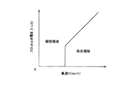
例えば、電子制御装置50は、専ら加速走行時には、例えば図4に示すようなスロットル弁開度θTHおよび車速Vを変数とする二次元座標において解放領域、係合領域を有する予め記憶された関係(マップ、ロックアップ領域線図)から実際のスロットル弁開度θTHおよび車速Vに基づいて係合領域、解放領域のいずれの領域に属するかを判断し、その判断した領域の作動状態となるようにロックアップクラッチ26の作動状態を切り換えるロックアップ制御指令信号を油圧制御回路100へ出力する。油圧制御回路100は、上記ロックアップ制御指令信号に従ってロックアップクラッチ26の作動状態が切り換えられるようにソレノイド弁DSUを作動させる。
For example, the
ここで、本実施例の油圧制御回路100においては、トルクコンバータ14による攪拌によって加熱された作動油を冷却する為のクーラ124が第1油路122の下流側にチェックバルブ126を介して接続されている。尚、このチェックバルブ126は必ずしも備えられる必要はない。
Here, in the
また、ロックアップオフ時にトルクコンバータ14の循環流量が過剰になることが抑制され且つトルクコンバータ14の発熱が適切に抑えられる程度の循環流量が確保されるように、第1油路122に流れる作動油を調整する為の第1オリフィス128が第1油路122のクーラ124よりも上流側に備えられている。
Further, the operation that flows through the
また、第2油路118に流出する作動油(余剰油)が過剰になることが抑制されるように、第2油路118に流れる作動油を調整する為の第2オリフィス130が第2油路118に備えられている。
Further, the
ところで、第1油路122と第2油路118とのそれぞれの下流側に潤滑のための潤滑経路(潤滑系統)を接続し、潤滑経路を2経路設けることも考えられるが、クーラ流量が第1油路122における潤滑経路の潤滑流量よりも多く必要とされる場合に、第2油路118における潤滑経路に潤滑流量を流さなければならないこともあり潤滑流量が過剰になってしまう。そこで、本実施例の油圧制御回路100においては、潤滑経路を1経路とする為に、第2油路118の下流側が第1油路122の第1オリフィス128とクーラ124との間に接続されると共に、クーラ124よりも下流側に潤滑経路132が接続されてクーラ124と潤滑経路132とが直列化されている。
By the way, it is conceivable to connect a lubrication path (lubricating system) for lubrication on the downstream side of each of the
また、本実施例の油圧制御回路100においては、クーラ124を保護するための安全弁としてのクーラバイパスバルブ134が第1油路122の下流側にクーラ124と並列に備えられている。
In the
このクーラバイパスバルブ134は、ロックアップオフ時にはクーラ124へ流入する作動油が過剰にならないように作動油をオイルパンに直接排出する。このとき、オイルパンに直接排出する作動油の流量が必要最小限とされるように、例えばクーラ124が保護される範囲で可及的に多くの流量がクーラ124へ流入するように、クーラバイパスバルブ134の開放圧Poが設定されている。 The cooler bypass valve 134 directly discharges the hydraulic oil to the oil pan so that the hydraulic oil flowing into the cooler 124 does not become excessive when the lock-up is off. At this time, in order to minimize the flow rate of the hydraulic oil discharged directly to the oil pan, for example, the cooler bypass so that as much flow rate as possible flows into the cooler 124 as long as the cooler 124 is protected. An opening pressure Po of the valve 134 is set.
また、ロックアップクラッチ26が係合状態であるときには、第2油路118からの作動油のみがクーラ124へ流れることから、作動油がクーラバイパスバルブ134から無駄に排出されないように、クーラバイパスバルブ134を開かせない。つまり、ロックアップクラッチ26の係合状態ではクーラバイパスバルブ134が開かないように、クーラバイパスバルブ134の開放圧Poはロックアップクラッチ26が係合状態であるときの第2オリフィス130とクーラ124との間の油圧P1より大きな値に設定されている。
Further, when the
図5は、ロックアップクラッチ26の係合状態において、第2油路118から潤滑経路132へ流れる潤滑流量QLUBを第2オリフィス130を通過する流量を用いて説明するための模式図である。
FIG. 5 is a schematic diagram for explaining the lubrication flow rate Q LUB flowing from the
図5において、第2オリフィス130前の油圧PL2(すなわち第2ライン油圧)、第2オリフィス130後の油圧P1、予め実験的に求められた流量係数C、第2オリフィス130の断面積SA、クーラ124以降の潤滑経路132までの等価オリフィス136の通過面積(断面積)SB、作動油の密度ρとすると、第2オリフィス130を通過する流量と略等しくなるである潤滑流量QLUBと第2オリフィス130前後の油圧との関係は図中式(5)および式(6)にて表される。
In FIG. 5, the hydraulic pressure P L2 before the second orifice 130 (ie, the second line hydraulic pressure), the hydraulic pressure P1 after the
図5の式(6)から必要な潤滑流量QLUBに基づいて油圧P1が決定され、 油圧P1<開放圧Po であればクーラバイパスバルブ134は開かない。第2オリフィス130は、式(5)からロックアップクラッチ26の係合状態においてクーラバイパスバルブ134が開かず、必要な潤滑流量QLUBが確保される程度に絞られているのである。
The oil pressure P1 is determined based on the necessary lubrication flow rate Q LUB from the equation (6) in FIG. 5. If the oil pressure P1 <the open pressure Po, the cooler bypass valve 134 is not opened. From the formula (5), the
本実施例の油圧制御回路100においては、出力ポート112tから吸入油路120へ排出される余剰油の流量QSは、第2ライン油路116へ排出された作動油の流量から必要流量(=トルクコンバータ14の循環流量+潤滑流量+クーラ流量+クーラバイパスバルブ134からの排出される流量)と各部の洩れ量(消費流量)を減算した流量とされることから、前述の通り油圧制御回路100が構成されたことにより余剰油の流量QSが多くされる。
In the
上述のように、本実施例によれば、第1油路122のクーラ124よりも上流側に第1オリフィス128が備えられると共に第2油路118に第2オリフィス130が備えられるので、第1油路122および第2油路118に流れる作動油の流量はそれぞれ第1オリフィス128および第2オリフィス130により調整されてそれら流量が過剰になることが抑制される。また、第2油路118の下流側が第1油路122の第1オリフィス128とクーラ124との間に接続されると共にクーラ124よりも下流側に潤滑経路132が接続されるので、第2油路118に流れる作動油がクーラ124と同じ系統とされた潤滑経路132に流されると共にクーラ124と潤滑経路132とが直列化されて、クーラ流量と潤滑流量とが同じになる。これらにより、セカンダリレギュレータバルブ112からオイルポンプ28の上流側に流出される作動油の流量を多くすることができる。
As described above, according to this embodiment, the
また、本実施例によれば、第1油路122の下流側にクーラ124と並列にクーラバイパスバルブ134を備え、クーラバイパスバルブ134の開放圧Poは、ロックアップクラッチ26の係合状態ではそのクーラバイパスバルブ134が開かないように設定されているので、クーラバイパスバルブ134から流出させられる作動油の流量を抑えることができて、セカンダリレギュレータバルブ112からオイルポンプ28の上流側に流出される作動油の流量を一層多くすることができる。
Further, according to this embodiment, the cooler bypass valve 134 is provided in parallel with the cooler 124 on the downstream side of the
以上、本発明の実施例を図面に基づいて詳細に説明したが、本発明はその他の態様においても適用される。 As mentioned above, although the Example of this invention was described in detail based on drawing, this invention is applied also in another aspect.
例えば、前述の実施例では、油圧P1<開放圧Po となるように第2オリフィス130が絞られて、ロックアップクラッチ26の係合状態においてクーラバイパスバルブ134が開かないようにされたが、クーラバイパスバルブ134の開放圧Poをより高く設定することで 油圧P1<開放圧Po としても良い。また、図5の式(5)から明らかなように、第2ライン油圧PL2を低くするようにしても良い。但し、第2ライン油圧PL2は、ロックアップクラッチ26のトルク容量を満足するように設定される必要があるので、このトルク容量を満足する範囲で設定されるか、或いはトルク容量を満足するという制約がない場合に低くしても良い。
For example, in the above-described embodiment, the
また、前述の実施例は、プライマリレギュレータバルブ110からの余剰油を調圧するセカンダリレギュレータバルブ112からオイルポンプ28の上流側へ余剰油が排出されるものであったが、これに限らず、例えば2つの調圧弁を備えずオイルポンプ28から吐出される作動油を直接的に調圧する調圧弁からオイルポンプ28の上流側へ余剰油が排出される場合でも本発明は適用され得る。この場合には、オイルポンプ28から吐出されて直接的に調圧された作動油がトルクコンバータ14等へ循環させられる。
In the above-described embodiment, the surplus oil is discharged from the
また、前述の実施例では、動力伝達装置を構成する変速機としてベルト式の無段変速機が用いられたが、これに限らず、良く知られたトロイダル型無段変速機や遊星歯車式の自動変速機等の他の変速機が用いられてもよい。要は、動力伝達経路にロックアップクラッチ26を有するトルクコンバータ14が備えられておれば良い。
In the above-described embodiment, a belt-type continuously variable transmission is used as a transmission constituting the power transmission device. However, the present invention is not limited to this, and a well-known toroidal-type continuously variable transmission or planetary gear-type transmission is used. Other transmissions such as an automatic transmission may be used. In short, it is sufficient that the
また、前述の実施例において、流体伝動装置としてロックアップクラッチ26が備えられているトルクコンバータ14が用いられていたが、トルクコンバータ14に替えて、トルク増幅作用のない流体継手(フルードカップリング)などの他の流体式動力伝達装置が用いられても良い。
In the above-described embodiment, the
なお、上述したのはあくまでも一実施形態であり、本発明は当業者の知識に基づいて種々の変更、改良を加えた態様で実施することができる。 The above description is only an embodiment, and the present invention can be implemented in variously modified and improved forms based on the knowledge of those skilled in the art.
10:車両用駆動装置(車両用動力伝達装置)
14:トルクコンバータ(流体伝動装置)
26:ロックアップクラッチ
28:オイルポンプ
100:油圧制御回路(油圧制御装置)
112:セカンダリレギュレータバルブ(リリーフ型の調圧弁)
118:第2油路
122:第1油路
124:クーラ
128:第1オリフィス
130:第2オリフィス
132:潤滑経路
134:クーラバイパスバルブ(安全弁)
10: Vehicle drive device (vehicle power transmission device)
14: Torque converter (fluid transmission)
26: Lock-up clutch 28: Oil pump 100: Hydraulic control circuit (hydraulic control device)
112: Secondary regulator valve (relief type pressure regulating valve)
118: Second oil passage 122: First oil passage 124: Cooler 128: First orifice 130: Second orifice 132: Lubrication passage 134: Cooler bypass valve (safety valve)
Claims (2)
前記第1油路の前記クーラよりも上流側に第1オリフィスを備えると共に、前記第2油路に第2オリフィスを備える一方で、前記第2油路の下流側が前記第1油路の前記第1オリフィスと前記クーラとの間に接続されると共に、前記クーラよりも下流側に潤滑経路が接続されていることを特徴とする車両用動力伝達装置の油圧制御装置。 In a vehicle power transmission device including a fluid transmission device with a lock-up clutch in which hydraulic oil discharged from an oil pump is regulated and circulated by a relief-type pressure regulating valve, the lock-up clutch is engaged and released. And the hydraulic oil circulation path is switched, and in the released state of the lock-up clutch, the outflow destination of the hydraulic oil from the fluid transmission device is a first oil path to which a cooler is connected downstream, A hydraulic control device for a vehicle power transmission device, wherein a part of surplus oil flowing out from the pressure regulating valve is allowed to flow out to the second oil passage and the other part is allowed to flow out upstream of the oil pump. There,
A first orifice is provided upstream of the cooler of the first oil passage, and a second orifice is provided in the second oil passage, while the downstream side of the second oil passage is the first orifice of the first oil passage. A hydraulic control device for a vehicle power transmission device, wherein the hydraulic control device is connected between one orifice and the cooler, and a lubrication path is connected downstream of the cooler.
前記安全弁の開放圧は、前記ロックアップクラッチの係合状態では該安全弁が開かないように設定されているものである請求項1の車両用動力伝達装置の油圧制御装置。 A safety valve in parallel with the cooler on the downstream side of the first oil passage;
2. The hydraulic control device for a vehicle power transmission device according to claim 1, wherein the opening pressure of the safety valve is set so that the safety valve does not open when the lock-up clutch is engaged.
Priority Applications (4)
| Application Number | Priority Date | Filing Date | Title |
|---|---|---|---|
| JP2006231020A JP4179364B2 (en) | 2006-08-28 | 2006-08-28 | Hydraulic control device for power transmission device for vehicle |
| US11/882,226 US7669701B2 (en) | 2006-08-28 | 2007-07-31 | Hydraulic pressure control apparatus for a vehicular power transmitting device |
| EP07113703A EP1895199B1 (en) | 2006-08-28 | 2007-08-02 | Hydraulic pressure control apparatus for a vehicular power transmitting device |
| CNB2007101458163A CN100523565C (en) | 2006-08-28 | 2007-08-28 | Hydraulic pressure control apparatus for a vehicular power transmitting device |
Applications Claiming Priority (1)
| Application Number | Priority Date | Filing Date | Title |
|---|---|---|---|
| JP2006231020A JP4179364B2 (en) | 2006-08-28 | 2006-08-28 | Hydraulic control device for power transmission device for vehicle |
Publications (2)
| Publication Number | Publication Date |
|---|---|
| JP2008051318A JP2008051318A (en) | 2008-03-06 |
| JP4179364B2 true JP4179364B2 (en) | 2008-11-12 |
Family
ID=38669830
Family Applications (1)
| Application Number | Title | Priority Date | Filing Date |
|---|---|---|---|
| JP2006231020A Expired - Fee Related JP4179364B2 (en) | 2006-08-28 | 2006-08-28 | Hydraulic control device for power transmission device for vehicle |
Country Status (4)
| Country | Link |
|---|---|
| US (1) | US7669701B2 (en) |
| EP (1) | EP1895199B1 (en) |
| JP (1) | JP4179364B2 (en) |
| CN (1) | CN100523565C (en) |
Cited By (2)
| Publication number | Priority date | Publication date | Assignee | Title |
|---|---|---|---|---|
| US9695928B2 (en) | 2014-03-12 | 2017-07-04 | Honda Motor Co., Ltd. | Transmission lubrication system |
| CN107202156A (en) * | 2016-03-17 | 2017-09-26 | 本田技研工业株式会社 | The hydraulic system of transmission device for vehicle |
Families Citing this family (14)
| Publication number | Priority date | Publication date | Assignee | Title |
|---|---|---|---|---|
| JP4375462B2 (en) * | 2007-08-31 | 2009-12-02 | トヨタ自動車株式会社 | Axial piston pump and power transmission device including the same |
| JP4605245B2 (en) | 2008-04-24 | 2011-01-05 | トヨタ自動車株式会社 | Hydraulic control device |
| JP2010242635A (en) * | 2009-04-07 | 2010-10-28 | Toyota Motor Corp | Hydraulic circuit |
| JP5177112B2 (en) * | 2009-09-30 | 2013-04-03 | アイシン・エィ・ダブリュ株式会社 | Hydraulic control device for automatic transmission |
| JP5465325B2 (en) * | 2010-05-12 | 2014-04-09 | 本田技研工業株式会社 | Hydraulic control device for automatic transmission |
| DE112010005946B4 (en) | 2010-10-19 | 2016-08-04 | Toyota Jidosha Kabushiki Kaisha | Hydraulic control unit for vehicle automatic transmission |
| JP5418486B2 (en) * | 2010-12-09 | 2014-02-19 | アイシン・エィ・ダブリュ株式会社 | Power transmission device |
| JP5556712B2 (en) * | 2011-03-22 | 2014-07-23 | アイシン・エィ・ダブリュ株式会社 | Hydraulic control device |
| DE102011075411A1 (en) * | 2011-05-06 | 2012-11-08 | Robert Bosch Gmbh | Transmission of a motor vehicle with an input shaft and an output shaft |
| US10274078B2 (en) | 2014-02-10 | 2019-04-30 | Honda Motor Co., Ltd. | Hydraulic circuit for transmission |
| US10544840B2 (en) | 2017-12-11 | 2020-01-28 | Caterpillar Inc. | System and method for reducing clutch fill time |
| CN111448371B (en) * | 2017-12-29 | 2023-01-20 | 沃尔沃卡车集团 | Fluid circuit and method for controlling a fluid flow supplied to at least one device |
| CN109854693A (en) * | 2018-12-30 | 2019-06-07 | 芜湖万里扬变速器有限公司 | Stepless speed variator system suitable for electric car |
| CN115066556A (en) * | 2020-03-04 | 2022-09-16 | 舍弗勒技术股份两合公司 | Method for actuating a hydraulic device |
Family Cites Families (12)
| Publication number | Priority date | Publication date | Assignee | Title |
|---|---|---|---|---|
| JPS62200070A (en) * | 1986-02-27 | 1987-09-03 | Aisin Seiki Co Ltd | Control circuit for fluid joint with direct coupling clutch |
| EP0356036B1 (en) * | 1988-08-02 | 1995-01-04 | Toyota Jidosha Kabushiki Kaisha | Hydraulic control device for automatic transmission for vehicle having clutch operable in two speed stages and two parallel hydraulic pressure supply passages therefor |
| KR0138098B1 (en) * | 1988-12-01 | 1998-04-30 | 라이문트라우에 및 에델버트 발터어 | Control device for a frictinally engaging clutch |
| JPH0765676B2 (en) | 1989-03-31 | 1995-07-19 | 日産自動車株式会社 | Oil quantity control device for automatic transmission |
| US5007309A (en) * | 1989-06-08 | 1991-04-16 | Rockwell International Corporation | Automatic transmission control system and method of operation |
| JP2846362B2 (en) | 1989-09-26 | 1999-01-13 | ジャトコ株式会社 | Hydraulic control device for lock-up clutch |
| US5163540A (en) * | 1992-02-24 | 1992-11-17 | Saturn Corporation | Control valving for a torque converter and clutch assembly |
| JP2803497B2 (en) | 1992-11-06 | 1998-09-24 | 日産自動車株式会社 | Line pressure control device for automatic transmission |
| JP3787921B2 (en) | 1996-10-24 | 2006-06-21 | アイシン精機株式会社 | Lockup hydraulic control device for torque converter |
| JP3539313B2 (en) * | 1999-10-18 | 2004-07-07 | 日産自動車株式会社 | Lockup control device for torque converter |
| JP3929739B2 (en) | 2001-10-11 | 2007-06-13 | アイシン・エィ・ダブリュ株式会社 | Hydraulic control device for automatic transmission |
| DE102004003692A1 (en) * | 2004-01-24 | 2005-08-18 | Zf Friedrichshafen Ag | Hydraulic circuit arrangement of an automatic transmission for motor vehicles |
-
2006
- 2006-08-28 JP JP2006231020A patent/JP4179364B2/en not_active Expired - Fee Related
-
2007
- 2007-07-31 US US11/882,226 patent/US7669701B2/en active Active
- 2007-08-02 EP EP07113703A patent/EP1895199B1/en not_active Ceased
- 2007-08-28 CN CNB2007101458163A patent/CN100523565C/en not_active Expired - Fee Related
Cited By (4)
| Publication number | Priority date | Publication date | Assignee | Title |
|---|---|---|---|---|
| US9695928B2 (en) | 2014-03-12 | 2017-07-04 | Honda Motor Co., Ltd. | Transmission lubrication system |
| CN107202156A (en) * | 2016-03-17 | 2017-09-26 | 本田技研工业株式会社 | The hydraulic system of transmission device for vehicle |
| US9995383B2 (en) | 2016-03-17 | 2018-06-12 | Honda Motor Co., Ltd. | Hydraulic system of vehicle transmission device |
| CN107202156B (en) * | 2016-03-17 | 2019-05-07 | 本田技研工业株式会社 | The hydraulic system of transmission device for vehicle |
Also Published As
| Publication number | Publication date |
|---|---|
| CN100523565C (en) | 2009-08-05 |
| JP2008051318A (en) | 2008-03-06 |
| EP1895199A2 (en) | 2008-03-05 |
| US20080051251A1 (en) | 2008-02-28 |
| EP1895199A3 (en) | 2010-04-07 |
| EP1895199B1 (en) | 2011-10-05 |
| US7669701B2 (en) | 2010-03-02 |
| CN101135372A (en) | 2008-03-05 |
Similar Documents
| Publication | Publication Date | Title |
|---|---|---|
| JP4179364B2 (en) | Hydraulic control device for power transmission device for vehicle | |
| JP4187023B2 (en) | Hydraulic control device for power transmission device for vehicle | |
| JP4238895B2 (en) | Shift control device for continuously variable transmission for vehicle | |
| JP4605245B2 (en) | Hydraulic control device | |
| JP5716845B2 (en) | Hydraulic control device and vehicle control device | |
| KR100793868B1 (en) | Manual valve of hydraulic control system for continuously variable transmission | |
| JP5435145B2 (en) | Hydraulic control device for automatic transmission for vehicle | |
| JP5125030B2 (en) | Hydraulic control device for continuously variable transmission for vehicle | |
| JP2007010090A (en) | Hydraulic control device | |
| JPWO2017163855A1 (en) | Hydraulic control device | |
| JP4736831B2 (en) | Control device for continuously variable transmission for vehicle | |
| JP4892969B2 (en) | Vehicle control device | |
| JP3630883B2 (en) | Hydraulic control circuit for continuously variable transmission | |
| JP2007177833A (en) | Shift controller of continuously variable transmission for vehicle | |
| KR100282899B1 (en) | Hydraulic Control Device for Automotive Automatic Transmission | |
| JP4811151B2 (en) | Shift control device for continuously variable transmission for vehicle | |
| JP5125668B2 (en) | Shift control device for continuously variable transmission for vehicle | |
| JP2007177834A (en) | Control device of continuously variable transmission | |
| JP2020076459A (en) | Hydraulic control device | |
| JP4735225B2 (en) | Hydraulic control device for continuously variable transmission | |
| JP2010144885A (en) | Device for controlling lubricating oil passage of belt type continuously variable transmission for vehicle | |
| JP2008095907A (en) | Speed change control device for vehicular continuously variable transmission | |
| JP5125654B2 (en) | Shift control device for continuously variable transmission for vehicle | |
| JP2012246959A (en) | Hydraulic control apparatus for vehicle transmission | |
| JP5884529B2 (en) | Hydraulic supply device for drivetrain |
Legal Events
| Date | Code | Title | Description |
|---|---|---|---|
| TRDD | Decision of grant or rejection written | ||
| A977 | Report on retrieval |
Free format text: JAPANESE INTERMEDIATE CODE: A971007 Effective date: 20080730 |
|
| A01 | Written decision to grant a patent or to grant a registration (utility model) |
Free format text: JAPANESE INTERMEDIATE CODE: A01 Effective date: 20080805 |
|
| A01 | Written decision to grant a patent or to grant a registration (utility model) |
Free format text: JAPANESE INTERMEDIATE CODE: A01 |
|
| A61 | First payment of annual fees (during grant procedure) |
Free format text: JAPANESE INTERMEDIATE CODE: A61 Effective date: 20080818 |
|
| R151 | Written notification of patent or utility model registration |
Ref document number: 4179364 Country of ref document: JP Free format text: JAPANESE INTERMEDIATE CODE: R151 |
|
| FPAY | Renewal fee payment (event date is renewal date of database) |
Free format text: PAYMENT UNTIL: 20110905 Year of fee payment: 3 |
|
| FPAY | Renewal fee payment (event date is renewal date of database) |
Free format text: PAYMENT UNTIL: 20110905 Year of fee payment: 3 |
|
| FPAY | Renewal fee payment (event date is renewal date of database) |
Free format text: PAYMENT UNTIL: 20120905 Year of fee payment: 4 |
|
| FPAY | Renewal fee payment (event date is renewal date of database) |
Free format text: PAYMENT UNTIL: 20130905 Year of fee payment: 5 |
|
| LAPS | Cancellation because of no payment of annual fees |