JP4178955B2 - Drive control - Google Patents
Drive control Download PDFInfo
- Publication number
- JP4178955B2 JP4178955B2 JP2002584465A JP2002584465A JP4178955B2 JP 4178955 B2 JP4178955 B2 JP 4178955B2 JP 2002584465 A JP2002584465 A JP 2002584465A JP 2002584465 A JP2002584465 A JP 2002584465A JP 4178955 B2 JP4178955 B2 JP 4178955B2
- Authority
- JP
- Japan
- Prior art keywords
- motor
- signal
- circuit
- frequency
- control
- Prior art date
- Legal status (The legal status is an assumption and is not a legal conclusion. Google has not performed a legal analysis and makes no representation as to the accuracy of the status listed.)
- Expired - Fee Related
Links
Images


Classifications
-
- B—PERFORMING OPERATIONS; TRANSPORTING
- B60—VEHICLES IN GENERAL
- B60L—PROPULSION OF ELECTRICALLY-PROPELLED VEHICLES; SUPPLYING ELECTRIC POWER FOR AUXILIARY EQUIPMENT OF ELECTRICALLY-PROPELLED VEHICLES; ELECTRODYNAMIC BRAKE SYSTEMS FOR VEHICLES IN GENERAL; MAGNETIC SUSPENSION OR LEVITATION FOR VEHICLES; MONITORING OPERATING VARIABLES OF ELECTRICALLY-PROPELLED VEHICLES; ELECTRIC SAFETY DEVICES FOR ELECTRICALLY-PROPELLED VEHICLES
- B60L15/00—Methods, circuits, or devices for controlling the traction-motor speed of electrically-propelled vehicles
- B60L15/20—Methods, circuits, or devices for controlling the traction-motor speed of electrically-propelled vehicles for control of the vehicle or its driving motor to achieve a desired performance, e.g. speed, torque, programmed variation of speed
- B60L15/2036—Electric differentials, e.g. for supporting steering vehicles
-
- B—PERFORMING OPERATIONS; TRANSPORTING
- B60—VEHICLES IN GENERAL
- B60L—PROPULSION OF ELECTRICALLY-PROPELLED VEHICLES; SUPPLYING ELECTRIC POWER FOR AUXILIARY EQUIPMENT OF ELECTRICALLY-PROPELLED VEHICLES; ELECTRODYNAMIC BRAKE SYSTEMS FOR VEHICLES IN GENERAL; MAGNETIC SUSPENSION OR LEVITATION FOR VEHICLES; MONITORING OPERATING VARIABLES OF ELECTRICALLY-PROPELLED VEHICLES; ELECTRIC SAFETY DEVICES FOR ELECTRICALLY-PROPELLED VEHICLES
- B60L50/00—Electric propulsion with power supplied within the vehicle
- B60L50/50—Electric propulsion with power supplied within the vehicle using propulsion power supplied by batteries or fuel cells
- B60L50/52—Electric propulsion with power supplied within the vehicle using propulsion power supplied by batteries or fuel cells characterised by DC-motors
-
- B—PERFORMING OPERATIONS; TRANSPORTING
- B62—LAND VEHICLES FOR TRAVELLING OTHERWISE THAN ON RAILS
- B62D—MOTOR VEHICLES; TRAILERS
- B62D11/00—Steering non-deflectable wheels; Steering endless tracks or the like
- B62D11/02—Steering non-deflectable wheels; Steering endless tracks or the like by differentially driving ground-engaging elements on opposite vehicle sides
- B62D11/04—Steering non-deflectable wheels; Steering endless tracks or the like by differentially driving ground-engaging elements on opposite vehicle sides by means of separate power sources
-
- B—PERFORMING OPERATIONS; TRANSPORTING
- B62—LAND VEHICLES FOR TRAVELLING OTHERWISE THAN ON RAILS
- B62D—MOTOR VEHICLES; TRAILERS
- B62D11/00—Steering non-deflectable wheels; Steering endless tracks or the like
- B62D11/02—Steering non-deflectable wheels; Steering endless tracks or the like by differentially driving ground-engaging elements on opposite vehicle sides
- B62D11/06—Steering non-deflectable wheels; Steering endless tracks or the like by differentially driving ground-engaging elements on opposite vehicle sides by means of a single main power source
- B62D11/10—Steering non-deflectable wheels; Steering endless tracks or the like by differentially driving ground-engaging elements on opposite vehicle sides by means of a single main power source using gearings with differential power outputs on opposite sides, e.g. twin-differential or epicyclic gears
- B62D11/14—Steering non-deflectable wheels; Steering endless tracks or the like by differentially driving ground-engaging elements on opposite vehicle sides by means of a single main power source using gearings with differential power outputs on opposite sides, e.g. twin-differential or epicyclic gears differential power outputs being effected by additional power supply to one side, e.g. power originating from secondary power source
- B62D11/18—Steering non-deflectable wheels; Steering endless tracks or the like by differentially driving ground-engaging elements on opposite vehicle sides by means of a single main power source using gearings with differential power outputs on opposite sides, e.g. twin-differential or epicyclic gears differential power outputs being effected by additional power supply to one side, e.g. power originating from secondary power source the additional power supply being supplied hydraulically
- B62D11/183—Control systems therefor
-
- B—PERFORMING OPERATIONS; TRANSPORTING
- B60—VEHICLES IN GENERAL
- B60L—PROPULSION OF ELECTRICALLY-PROPELLED VEHICLES; SUPPLYING ELECTRIC POWER FOR AUXILIARY EQUIPMENT OF ELECTRICALLY-PROPELLED VEHICLES; ELECTRODYNAMIC BRAKE SYSTEMS FOR VEHICLES IN GENERAL; MAGNETIC SUSPENSION OR LEVITATION FOR VEHICLES; MONITORING OPERATING VARIABLES OF ELECTRICALLY-PROPELLED VEHICLES; ELECTRIC SAFETY DEVICES FOR ELECTRICALLY-PROPELLED VEHICLES
- B60L2200/00—Type of vehicles
- B60L2200/22—Microcars, e.g. golf cars
-
- Y—GENERAL TAGGING OF NEW TECHNOLOGICAL DEVELOPMENTS; GENERAL TAGGING OF CROSS-SECTIONAL TECHNOLOGIES SPANNING OVER SEVERAL SECTIONS OF THE IPC; TECHNICAL SUBJECTS COVERED BY FORMER USPC CROSS-REFERENCE ART COLLECTIONS [XRACs] AND DIGESTS
- Y02—TECHNOLOGIES OR APPLICATIONS FOR MITIGATION OR ADAPTATION AGAINST CLIMATE CHANGE
- Y02T—CLIMATE CHANGE MITIGATION TECHNOLOGIES RELATED TO TRANSPORTATION
- Y02T10/00—Road transport of goods or passengers
- Y02T10/60—Other road transportation technologies with climate change mitigation effect
- Y02T10/64—Electric machine technologies in electromobility
-
- Y—GENERAL TAGGING OF NEW TECHNOLOGICAL DEVELOPMENTS; GENERAL TAGGING OF CROSS-SECTIONAL TECHNOLOGIES SPANNING OVER SEVERAL SECTIONS OF THE IPC; TECHNICAL SUBJECTS COVERED BY FORMER USPC CROSS-REFERENCE ART COLLECTIONS [XRACs] AND DIGESTS
- Y02—TECHNOLOGIES OR APPLICATIONS FOR MITIGATION OR ADAPTATION AGAINST CLIMATE CHANGE
- Y02T—CLIMATE CHANGE MITIGATION TECHNOLOGIES RELATED TO TRANSPORTATION
- Y02T10/00—Road transport of goods or passengers
- Y02T10/60—Other road transportation technologies with climate change mitigation effect
- Y02T10/70—Energy storage systems for electromobility, e.g. batteries
-
- Y—GENERAL TAGGING OF NEW TECHNOLOGICAL DEVELOPMENTS; GENERAL TAGGING OF CROSS-SECTIONAL TECHNOLOGIES SPANNING OVER SEVERAL SECTIONS OF THE IPC; TECHNICAL SUBJECTS COVERED BY FORMER USPC CROSS-REFERENCE ART COLLECTIONS [XRACs] AND DIGESTS
- Y02—TECHNOLOGIES OR APPLICATIONS FOR MITIGATION OR ADAPTATION AGAINST CLIMATE CHANGE
- Y02T—CLIMATE CHANGE MITIGATION TECHNOLOGIES RELATED TO TRANSPORTATION
- Y02T10/00—Road transport of goods or passengers
- Y02T10/60—Other road transportation technologies with climate change mitigation effect
- Y02T10/72—Electric energy management in electromobility
-
- Y—GENERAL TAGGING OF NEW TECHNOLOGICAL DEVELOPMENTS; GENERAL TAGGING OF CROSS-SECTIONAL TECHNOLOGIES SPANNING OVER SEVERAL SECTIONS OF THE IPC; TECHNICAL SUBJECTS COVERED BY FORMER USPC CROSS-REFERENCE ART COLLECTIONS [XRACs] AND DIGESTS
- Y10—TECHNICAL SUBJECTS COVERED BY FORMER USPC
- Y10S—TECHNICAL SUBJECTS COVERED BY FORMER USPC CROSS-REFERENCE ART COLLECTIONS [XRACs] AND DIGESTS
- Y10S388/00—Electricity: motor control systems
- Y10S388/907—Specific control circuit element or device
- Y10S388/911—Phase locked loop
Abstract
Description
技術分野
本発明は電動駆動部を備える駆動体に適用される駆動制御技術に関するものである。この駆動体として、特に電動モーターを駆動部として備える、例えば電気自動車、電動車椅子、電動カート等の電動走行車両がある。本発明の駆動制御技術は、電動建設機械、電動福祉器具、電動ロボット、電動玩具、電動飛行機、カメラやプロジェクター等の電動光学機器等を構成する駆動体に適用することも可能である。また、本発明はエアコン、ファンモータ用ストーブ等の家庭電化製品に応用することができる。
背景技術
電動走行車輌は、駆動制御手段が電動モーターを回転制御することによって走行する。駆動制御手段は、この電動モーターの速度(回転速度)を調整して電動車輌の速度を調整している。速度調整は、電動モーターに供給される供給電圧を可変にして電動モーターへの供給電力を制御することによって行われる。例えば、乗員がアクセルペダルやレバーを操作し、その操作量に基づいて加速度が駆動制御手段に設定されると、電動車輌は設定された加速度の下で走行する。車輌が所望の速度に達し、乗員がアクセルペダル又はアクセルレバーを所定レベルに戻すと、電動車輌の速度が所定値に維持される。
一方、車輌を減速する場合には、乗員は、アクセルペダル又はアクセルレバーを車輌が減速される位置にセットする。これにより、駆動制御手段は電動モーターを所定の速度まで減速する制動制御を行う。アクセルペダル又はアクセルレバーの操作状態が維持されると車輌速度は所定値に維持される。
しかしながら、車輌速度の調整は運転者によって行なわれていたため、走行路の状態、例えば、走行路の傾斜や路面の摩擦状態によって車輌速度が一定せず、乗員は頻繁に車輌速度の調整の為にアクセル操作を行わざるを得なかった。
そこで、クルーズコントロールと称する技術が提供されている。この技術は、車輌の速度に外乱が生じても、車輌速度が指定速度で維持されるようにしたものである。
ステッピングモーター等回転速度の制御精度が高い電動モーターの場合は、このような速度制御が好適に実現できるが、一般的なACモーターやDCモーターでは、電源のオンで回転し、電源のオフで回転が停止するといった粗い回転制御が行われているに過ぎず、モーターの回転速度を微細かつ正確に制御する技術は未だ確立していない。
また、無段階変速機等の変速手段を用いれば、モーターの回転速度を一定としても末端の車輪の回転数を精度よく変更できるが、部品点数が増大し、重量も重くなるため、軽量で小回りが要求される小型電気自動車や電動車椅子、乗用カートには不向きであった。
また、駆動制御手段はマイクロコンピュータによって構成されており、電動モーターが高速回転の状態にある場合、電動モーターからの検出信号の周波数が高く、コンピュータ内の駆動制御処理が間に合わない。したがって、微細で迅速な制御を高速電動モーターに対して十分実行し得ないという問題があった。
また、電力制御での損失を熱として放出するために電力エネルギーを電動駆動体の駆動エネルギーに変換する上での変換効率が悪かった。
そこで、本発明の目的は電動駆動部の高速動作に十分対応した制御を実行できる駆動制御技術を提供することである。本発明の他の目的は、指定された動作状態で駆動部を的確に運転できる駆動制御技術を提供することである。本発明のさらに他の目的は、駆動部の制動制御時に発生する制動電力を有効に利用可能な駆動制御技術を提供することである。本発明のさらに他の目的は、前記駆動制御技術としてPLL制御を利用することである。本発明のさらに他の目的は、前記PLL制御に加えて、電動駆動部の運転状態に基づいて電動駆動部の電力を制御する駆動制御技術を提供することである。本発明のさらに他の目的は、電動駆動部への供給電圧のデューティ、或いは電圧を変化させて電動駆動部の動作を制御することである。本発明の他の目的は、制動電力を制御して駆動部の制動特性を変化させることである。本発明の他の目的は、この駆動制御技術を備えた駆動制御装置、及び駆動制御方法を提供することである。本発明のさらに他の目的は、この駆動制御技術によって制御される駆動体、特に電動車輌を提供することである。
発明の概要
前記目的を達成するために、本発明は駆動体を移動させるための電動回転駆動部を制御する駆動制御装置において、基準比較信号発生回路と、前記駆動部の速度を検出し、これを検出信号として出力する検出回路と、前記駆動部の速度指示回路と、前記駆動部の回転制御回路と、前記基準比較信号の位相と前記検出信号の位相とを比較し、比較結果を前記回転制御回路に出力する位相比較回路と、を備え、前記回転制御回路は、前記位相比較結果に基づいて前記駆動部の速度を前記速度指示に一致するように制御することを特徴とする。
本発明の実施形態において、駆動制御装置は次のように構成されている。前記基準比較信号発生回路と前記検出回路と前記位相比較回路とがPLL制御ブロックを構成している。前記位相比較回路は位相差信号を前記回転制御回路に出力し、この回転制御回路はこの位相差信号を前記駆動部に出力する。
前記回転制御回路は、前記位相差信号から前記駆動部が加速運転状態にあるか、制動運転状態にあるかを区別し、この結果に基づいて前記駆動部を運転制御する。
前記回転制御回路は、前記駆動部を加速させる駆動制御回路と、前記駆動部を制動させる制動制御回路と、からなる。回転制御回路は、前記駆動部の電力特性を変化させる特性変化手段を備える。特性変化手段は前記駆動部電力のデューティを変化させる。前記特性変化手段は前記駆動部電力の限界値を変化させる。前記特性変化手段は前記位相差信号のデューティに合わせて前記駆動部電力のデューティを変化させる。
前記特性変化手段は前記デューティの限界変化比を設定する。前記制動制御回路の負荷として前記駆動部の制動電力を蓄電可能な蓄電部が設けられる。制動制御回路は、前記位相差信号に基づいて前記蓄電部と前記駆動部とを断続制御する。前記特性変化手段は前記駆動部の負荷電力のデューティを変化させる。
前記特性変化手段は前記駆動部の負荷電力の電力限界値を変化させる。前記特性変化手段は前記駆動部の供給電力のデューティを変化させる。前記特性変化手段は前記駆動部の供給電力の限界値を変化させる。前記特性変化手段は前記駆動部電力のデューティ及びその限界値を変化させる。前記駆動制御回路は前記位相差信号のデューティに基づいて前記駆動部へ供給される駆動電圧を断続制御する。基準比較信号発生回路は基本周波数を分周して基準比較信号を出力し、前記回転制御回路は、前記速度指示回路の指示値に応じて前記分周比を変化させる。
前記検出回路は前記駆動部の回転センサーからの検出値を分周し、これを前記検出信号として出力し、前記回転制御回路は、前記速度指示回路の指示値に応じて前記分周比を変化させる。前記特性変化手段は、前記駆動部の運転状態に応じて前記電力特性を変化させてなる。前記特性変化手段は、前記駆動体の運転状態に応じて前記電力特性を変化させてなる。前記特性変化手段は、前記駆動部が加速又は制動の遷移領域にある場合に前記電力特性を変化させてなる。
本発明はまた駆動制御装置と、この駆動制御装置によって駆動制御される電動駆動部とを備えた駆動体からなる。本発明はまた、駆動制御装置と、この駆動制御装置によって駆動制御される電動駆動部とを備えた電気走行車輌からなる。
本発明の駆動制御方法は、駆動体を移動させるための電動回転駆動部を制御する駆動制御方法において、基準比較信号発生工程と、前記駆動部の速度を検出し、これを検出信号として出力する検出工程と、前記駆動部の速度指示工程と、前記駆動部の回転制御工程と、前記基準比較信号の位相と前記検出信号の位相とを比較する位相比較工程と、を備え、前記位相比較結果に基づいて前記駆動部の速度を前記速度指示に一致するように制御する。
発明を実施するための好適な形態
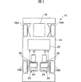
図1には、電動車輌10が示されている。図面上方が電動車輌の前進側である。この車両10は電動モーター(ステップピングモーター)12で駆動される。車体14には、前後に各2個の車輪16が設けられている。16Aは二つの前輪であり、16Bは二つの後輪である。この4個の車輪16により車両10が路面に対して接地支持されている。
前輪16Aは乗員によって操舵される操舵輪であり、この実施の形態では、乗員の操舵操作に基づいて、操舵制御部18は前輪16Aを左右に回転させることができる。なお、前輪をモーター等で電気的に回転制御しても良いし、乗員の操舵操作を機械的に前輪に伝達させるよう構成しても良い。また、各後輪(駆動輪)の回転速度を変化させることによって車輌を転舵するようにしても良い。
一方、後輪16Bのそれぞれがモーター駆動機構20に接続されている。この駆動機構はモーター駆動第1制御ブロック22(図2参照)の支配を受けている。モーター駆動機構20は、パルスモーター12の駆動を制御する第2制御ブロック24、モーターの駆動力を車軸16Bに伝達する伝達機構26とを備えている。駆動機構20は制御ブロック22の制御信号に基づいて、パルスモーター12を回転駆動させる。
図2に制御ブロック22の機能図を示す。速度ブロック22はPLL制御を利用して、基準比較周波数信号と電動モーターの検出周波数信号との位相を比較して電動モーター12の動作を制御している。
符合28は基準速度設定部28であり、水晶発振器30を備えている。水晶発振器から発振された基本周波数信号を分周して基準比較周波数信号が得られる。基準速度設定部28は、前記基本周波数信号を分周して比較信号を作り出す。分周比(率)はモーターに対する指示速度によって変更される。このようにして得られた基準周波数信号Mが、PLL制御ブロックの一部を構成する位相比較部32に入力される。車両(モーター)の指示速度は、後述の速度指示部において設定される。
位相比較部32には、周波数信号Nが指定速度設定部34から入力されており、位相比較部32は周波数信号Mと周波数信号Nとを比較して、両者の位相差を位相差信号としてLPF(ローパスフィルタ)36に出力する。
LPF36は、位相差信号を積分してノイズ等の高周波成分を除去して得た制御電圧信号をVCO(電圧制御発振回路)38に出力する。VCO38よりのクロック(周波数)信号は前記制御ブロック24のパルスモーター駆動用ドライバー40へ出力される。したがって、パルスモータードライバー40は、位相比較部32の位相差に応じてパルスモーター12を駆動させる。
パルスモーター12には、回転スピードエンコーダー42(回転速度検出器)が設けられている。このスピードエンコーダー42は各後輪の回転に対応した周波数のパルス信号を出力する。このエンコード信号は、実測値設定部44において後輪駆動用モーターの周波数信号Sとして記憶される。
この周波数信号Sは比較部46に入力される。比較部46においては、後輪の指示回転速度に対応する周波数信号と前記実測周波数信号Sとが比較されて両者の差が演算され、後輪の回転を増速するべきか、減速するべきか、さらには、どの程度の加速度で回転を増速又は減速するかを判断してN値(分周値)を決定する。
比較部46或いは指定速度設定部34は、前記周波数信号SをN分周してこれを指定速度周波数信号として指定速度設定部34に設定する。指定速度周波数信号Nは指定速度設定部34から前記位相比較部32に出力される。
したがって、周波数信号Mと周波数信号Nとの位相とが一致するような制御が既述のとおり実行されることにより、車両の速度が指示速度に収束制御されるように後輪の回転が制御される。既述の制御構成によれば、後輪の回転速度の制御がPLL制御方式によって正確であり、かつ簡単、迅速に行われる。
図3には、車両10の乗員が乗車する運転席に設けられたインストルメントパネル50が示されている。このインストルメントパネル50には、イグニションキーシリンダ52が設けられており、乗員はこのイグニッションキーシリンダ52にキーを挿入し、オン位置へキーを回すことで、駆動系の制御が開始される。
また、インストルメントパネル50には、モーターの指示速度を表示する指示速度表示部54と、現在の速度を表示する現在速度表示部56と、が設けられ、乗員は指示速度表示部54に表示される指示速度と、現在速度表示部56に表示される現在速度とを目視で比較することができる。なお、図3では、それぞれの表示部54、56を7セグメント表示としたが、ドットマトリクス表示や、アナログ表示であってもよい。
さらに、このインストルメントパネル50には、速度を指示する速度指示部48が設けられている。この速度指示部48は、増速キー58と、減速キー60と、停止キー62とに分かれている。増速キー58を操作し続けることで、車輌の目的指示速度を一定の割合で増速させることができ、その結果は指示速度表示部54に順次表示される。
また、減速キー60を操作し続けることで、速度を一定の割合で減速させることができ、その結果は順次指示速度表示部54に表示される。停止キー62は、車輌の目的速度を瞬時に0にするためのものであり、この停止キー62の操作によって、車輌は所定の加速度で減速されそして停止する。なお、車輌を停止、特に急制動の目的で別途そのためのキー又はペダルを設けることも可能である。なお、図1及び2の符合28及び30の部材が基準比較信号発生回路に相当し、符合42,44,46,及び34の各部材が検出回路に相当し、符合48の部材が回転速度指示回路に相当し、符合32,36および38の各部材が位相比較回路に相当する。また、本発明に係わる駆動制御装置は図示しないマイクロコンピュータによって制御される。
以下にモーターの駆動制御のためのフローを図4のフローチャート及び図5のタイムチャートに従い説明する。
まず、図4(A)に示す速度制御ルーチンのステップ100では、イグニッションキーシリンダ52にキーが挿入されて、オン状態となっているか否かが判断され、肯定判定されると、ステップ102へ移行する。
ステップ102では、指示速度が0であるか否かが判断され、肯定判定の場合には、指示速度が0であるため、ステップ100へ戻る。また、このステップ102において、否定判定されると速度指示があると判断されステップ104へ移行する。
ステップ104では、後輪の回転速度がスピードエンコーダ42によって測定されその実測値Sが読み取られる。次のステップ106では、車両(モーター)の指示速度と実速度とが比較され、これらに速度差があった場合、速度調整をする必要があるため、ステップ108において速度調整が必要か否かが判断される。
ステップ108において、速度調整が不要と判定(否定判定)された場合には、現在の速度が指示速度で安定していると判断され、ステップ100へ戻る。また、ステップ108で、速度調整が必要と判定された場合は、PLL制御による速度制御を行うべくステップ110へ移行する。ステップ110では、既述のとうり、位相比較部32において周波数信号の位相を比較し、位相差に基づいて駆動輪(後輪)の駆動を制御する。すなわち、ステップ112にあるように、後輪の現在の回転速度が指示された回転速度の周波数Nとなるように、基準となる周波数MをPLL回路に供給して、各駆動輪の電動モーター12を駆動制御する。
次のステップ114では、指示速度に変更があったか否かが判断される。すなわち、インストルメントパネル50の指示部48が操作されたか否かが判断され、指示速度に変更がない場合には、ステップ100へ戻り、現在の指示速度及び走行方向で車両10が走行制御される。
ここで、ステップ114において指示速度に変更があった場合には、比較部46での速度差の演算結果が変わるため、ステップ116へ移行して指示速度に対応する周波数信号Nの設定がなされ、以後、この変更後の周波数信号Nによって速度が制御される。
既述の制御ルーチン中に、停止キー62が操作されると、図4(B)の制動割込みルーチンが起動され、ステップ120においてモーター回転の実測値Sが読み取られると共に、ステップ122において、実測値Sに基づいて所定の加速度(マイナス)で減速が開始される。この結果、車両速度は0に収束するために後に車両10は停止する。
次に、位相制御部32からVC038を経てドライバ40に至る制御を図5のタイムチャートに従い、実際に車両10を増速、減速を繰り返して走行させた場合を例にとり説明する。なお、この図5において、制御パラメータとして、速度指示値、設定周波数信号N、PLL制御周波数信号M、及び周波数の増減を表すベクトル値が説明されている。
車両10が直進している形態を例としたが、車両の操舵時には、各後輪16Bに回転速度差が生じるように各後輪が異なる速度指示値で制御される。時間軸に対して速度指示値の変化が示されており、縦軸の紙面上方向が高速であり、紙面下方向が低速であることを示す。また、周波数増減に対応するベクトル表示は、ベクトルが紙面上方向に向いているときには、モーターの回転速度を高めるために、設定周波数信号Nの周波数を高めている(増速)ことを意味し、反対に下向きの場合にはその周波数を低くしている(減速)ことを意味する。なお、ベクトルが時間軸に対して平行になっている部分は、設定周波数信号Nの周波数を一定にして車両を定速度状態に維持する場合であることを意味する。
速度指示値を上げると、これに応じて先ず設定周波数Nが高くなり、これに追従するようにPLL制御周波数Mが高くなっている(周波数ベクトルが上向きとなる領域)。また、車両の速度指示値を下げると、これに応じて、まず設定周波数Nが低くなり、これに追従するようにPLL制御周波数Mが低くなる(周波数ベクトルが下向きの領域)。さらに、速度を維持する場合は、設定周波数NとPLL制御周波数Mとが一致する(周波数ベクトルが水平の領域)。周波数信号N,Mとの位相差に基づいて、既述の制御が前記PLL制御方式によって実現される。
以上説明したように、本実施の形態では、PLL回路による周波数位相比較制御を車両10の速度制御に用い、このPLL回路によってパルスモーター12の駆動状態を制御するようにしたため、予め指示した速度に車両速度が自動的に増速又は減速され、かつ、車両速度が指示速度になると車両はこの速度で安定して走行するため、乗員の負担を軽くすることができる。このような速度制御は、電動車椅子の制御には最適である。また、既述の速度制御によれば、乗員が不要に車両速度を増速する必要がないために、電動モーターの消費電力を必要最小限とすることができ、将来のソーラーカー等、電力が限られている車両に好適である。
本実施の形態では、速度検出手段として、スピードエンコーダ42を用い、パルスモーター12の回転を監視することで、車両10の速度を得るようにしたが、路面に向けて発光素子からレーザービームや赤外線を発光し、その反射光を検出してAC成分解析するといった非接触型のセンサーを適用して、速度を検出するようにしてもよい。
このような非接触型の速度計測機器としては、パーソナルコンピュータのマウスの移動速度や、野球やゴルフにおいて打球の速度を検出する技術に適用されている公知のものを広く適用できる(例えば、特開平6−313749公報、同7−134139公報を参照)。
このような非接触型のセンサーを用いることで、例えば、本実施の形態に記載したように駆動部(パルスモーター12)にスピードエンコーダ42を設置した場合における空転時の速度誤検出を防止することができる。
また、補助輪等、駆動力を有しない車輪にスピードエンコーダ42を設置した場合には、外部物体による補助輪ロック現象による回転ロック速度を検出してしまう。このような不具合も、非接触型のセンサーを用いれば解消することができる。
次に本発明に係わる駆動制御装置の他の実施形態について説明する。図6は、前記駆動輪(後輪)を前進制御するためのブロック図である。(1)はモーターを加速させる場合の制御ブロック図であり、(2)はモーターを制動制御する場合のブロック図である。符号60Aは全体制御を司るマイクロコンピュータを示す。このマイクロコンピュータには駆動輪の回転センサー42からの検出値と車輌速度の指示値、或いは前進又は後進のシフト状態を含む車輌運転のための各種データが入力されている。
符号62Aは基本周波数を発振する水晶発振器である。基本発振周波数はM分周器又はPLL回路からなる基準比較周波数信号形成回路64に入力され、ここで分周された所定の基準比較周波数信号66を生成する。基準比較周波数信号は位相比較回路回路68に入力される。マイクロコンピュータ60Aは駆動部の運転状態(速度)によって基本周波数を分周する分周特性(分周比)を変化させる制御信号を基準比較周波数形成回路64に送る。
位相比較回路68にはまた電動モーターM(直流モーター)の回転に応じてパルスを発生する回転センサー42からの検出信号が入力される。符号70はこの検出信号をN分周するN分周器である。N分周された検出信号は位相比較部68に入力され、位相比較部において二つの周波数信号の位相が比較される。
符号72はモーターを駆動させる駆動電圧を印加し、駆動電流(I−up)をモーターに供給するための駆動制御回路である。駆動制御回路は、駆動電流(電圧)の極性を車輌の前進又は後進に合わせて切り替える。符合74は、モーターを減速するための制動制御回路である。
符合76は制動制御回路に接続される負荷(蓄電部)である。I−down(図6(2)参照)は制動制御回路を流れる制動電流である。モーターの減速時、モーターは電源から切り離されて発電機(G)として機能し、制動制御回路に制動電流が流れてモーターが制動される。位相比較器68における位相比較結果に基づいて、駆動制御回路72と制動制御回路74とが切り換えられてモーターに接続される。
なお、モーターの回転方向が車輌を後退させる方向である場合には、駆動電流及び制動電流の極性が異なることを除いて図6の制御ブロックと同様である。
位相比較回路68において二つの周波数信号の位相差を求め、モーターの実速度が指示速度より遅くモーターを加速させる場合には、(1)に示すように、制御信号(UP)を駆動制御回路72に送り、モーターMに駆動電圧が印加させるようにモーターMと駆動制御回路72を接続する。このとき、制動制御回路74はモーターMと接続されていない。一方、モーターを制動させる場合には、(2)に示すように、モーターを減速させる制御信号(DOWN)を制動制御回路74に送り、モーターG(この場合は発電機となる。)を駆動電力供給電源から切り離すとともに、負荷(蓄電部76)に接続させる。このとき、モーターGは、駆動制御回路72に接続されていない。
既述のように、コンピュータ60Aは図6に係わる駆動制御装置全体を統括制御するものであり、基準比較周波数形成回路64、位相比較回68、駆動制御回路72,N分周器70,及び制動制御回路74を制御している。マイクロコンピュータは、モーターM(G)の回転速度等の運転状態や車輌の状態をセンサーによって検出して、モーターや車輌の運転状態を判定し、この判定結果に基づいてモーターの駆動電力や制動電力の特性値を変化させてモーターの運転状態を制御する。
電力特性値を変化させる一つの方式は、駆動電力・制動電力のデューティ(単位時間当たりのオン・オフタイムの比)を変えるために、位相比較回路68から出力される位相差信号(UP/DOWN)のデューティに対する限界比を定めることである。例えば、限界デューティ比が100%とは位相差信号のデューティがそのまま駆動制御回路72又は制動制御回路74に出力される。限界デューティ比が50%とは位相差信号のデューティが50%以下に制限される。すなわち、限界デューティ比がX%であると、位相差信号のデューティはそのX/100に制限される。したがって、デューティが100%の場合と同じ量のモーターの速度制御(加速・減速制御)を達成するのに、(100/X)倍時間を要することになる。したがって、限界デューティ比を低下させるほどモーターの速度変化を緩慢にする。
図7は、位相比較器68から出力される位相差信号のデューティを変化させるためのブロック図である。マイクロコンピュータ60Aは、限界デューティ比設定部61に車輌やモーターの運転状態に適した限界デューティ比を設定する。位相比較回路68は位相差信号を出力するに際して、この設定デューティ比を参照して位相差信号のデューティを変化させる。
図8(1)は駆動制御回路72のモーター駆動電圧印加回路の第1の実施形態であり、(2)はその第2の実施形態である。(1)に示す回路は、コンピュータ60Aからの制御信号をアナログに変換してDC出力電圧を設定するDC出力電圧設定部(回路)82と、DC出力電圧を昇圧するDC−DC変換部(回路)84と、直流電圧の極性を変化させる極性制御部(回路)86と、を含んで構成される。マイクロコンピュータ60Aは電動モーターMが車輌を前進する運転状態にあるか、又は後退する運転状態にあるかを判断して、極性制御部86からモーターMに印加される駆動電圧の極性を既述のように切り替える制御信号を極性制御部86に出力する。
位相比較回路68から位相差信号(UP)が極性制御部86に入力される。既述のように位相差信号(UP)が駆動制御回路72に出力されると、駆動制御回路72はモーターに接続される。位相差信号(UP)のHレベル(オンタイム)が極性制御部86に入力されるとモーター駆動用電圧がモーターMに印加される。
DC/DC変換部84は、所謂インバータを主構成としており、直流を交流に変換し、さらにこの交流を直流に変換する機能を有している。すなわち、所定値の直流電圧が入力されと、この直流電圧に基づいて交流電圧が生成される。交流電圧の周波数は、DC/DC変換部に備わる電圧検出部において検出された電圧に基づいて変更される。周波数の変更は交流電圧の実効値の変更となる。周波数が変更(電圧が変更)された交流は、再度直流に変換され、DC/DC変換部の出力部から出力される。極性制御部86の駆動電圧はDC/DC変換部の電圧検出部に帰還されているため、DC/DCからは電圧が安定した駆動電圧が極性制御部に出力される。
マイクロコンピュータ60Aはモーターへ印加する駆動電圧の電圧を変更するための制御信号をDC出力設定部82に設定する。この電圧の変更は、駆動部の電力特性を変化させる既述の第2の態様に相当する。電圧の変更の態様は、変化後の電圧と変化前の電圧の比として設定される。例えば、限界電圧比が50%とは、電圧の最大値の50%を上限にして電圧が減少されることを意味する。限界電圧比が低いほどモーターの加速・減速度が小さくなり車輌の速度変化が緩和されたものになる。
図8(2)は駆動電圧制御回路の第2の例である。この制御回路は、モーターの回転センサー42からの検出周波数信号を分周する分周器72Aと、既述のM分周器又はPLL部64から出力される基準比較周波数信号が入力される位相比較部72Bと、位相比較部の位相差信号が入力されるローパスフィルタ72Cと、ローパスフィルタからの出力信号をアナログ変換して増幅するアンプ72Dと、既述のDC−DC変換部84と、当該変換部から出力された電圧信号の極性を制御する極性制御部86とを備えている。
分周器72Aにおいて分周された回転センサーからの検出信号は前記位相比較部72Bに入力され、二つの信号の位相差信号をローパスフィルタ72Cに出力する。回転センサー42からの検出信号を位相比較部72Bに入力して位相差信号を形成し、この位相差信号に基づいてモーターに印加される電圧信号を形成しているために、モーターの回転状態が電圧信号の変化に直ちに反映される利点がある。したがって、モーターに印加される駆動電圧値が安定する効果がある。
符号72Eは増幅部72Dで増幅される電圧信号の限界電圧比をマイクロコンピュータ60からの制御信号によって設定可能な限界電圧比設定部である。マイクロコンピュータはモーターの速度が変更される場合、モーターの回転速度やモーターへの指示速度等から適切な分周値を選定し、これをM分器又はPLL回路64に、N分周器72Aにそれぞれ設定する。
図9は図8(2)において説明された駆動電圧印加制御のタイミング図である。(1)は水晶発振器からの基本周波数信号の波形である。(2)は回転センサー42からの出力パルスの波形である。(3)は基本周波数信号をM分周して得られた基準比較周波数信号の波形である。(4)は回転センサーからのパルス信号をN分周して得られた検出周波数信号の波形である。(5)は位相比較部72Bでの位相比較の結果出力された二つの検出周波数信号の位相差に基づく位相差信号の波形である。(6)は位相差信号がアナログ変換され増幅された電圧信号の特性である。(5)に示すように、二つの信号に位相差が発生すると、(6)に示すように限界電圧値が得られ、これがDC−DC変換部84において増幅され極性制御部86に供給される。(6)において、最大電圧値と限界電圧値との差が限界電圧比である。
図10の(1)は制動制御回路74のブロック図を示したものである。制動制御回路は負荷として、モーター(G)の制動電力を充電可能な蓄電池100Aと、充電制御回路101とを備えている。符合102Aはモーター(発電機)と充電制御回路とを断続するスイッチ回路である。モーターが充電回路と接続されていないときにはモーターは無負荷の状態となって空転する。モーターが充電制御回路と接続された状態ではモーターに制動電流が流れるためにモーターは発電制動器として機能する。
スイッチ回路102Aには位相比較回路68から既述のDOWNの信号が入力される。DOWNのHレベルが印加されるとモーターと充電制御回路とが接続される。102Bは交流−直流変換回路である。102Cは既述のDC−DC変換部に相当する電力変換回路である。102Dは蓄電池に充電する充電電圧を制御する充電電力制御回路である。充電電力制御回路102Dは蓄電池100Aの電圧を監視し、電力変換回路102Cに所定の電圧信号(T)を出力して電力変換回路102Cの出力電圧を充電圧以上に制御する。
図10(2)はモーターの回転数と電力変換部で発生する電力との関係を示す特性図である。モーターの回転速度が上がるにしたがって電力変換部の電力出力値が大きくなる。(3)はモーターの回転数と電力変換部の出力電圧値との関係を示した特性図であり、充電電力制御部102Dはモーターの回転速度が上がるにしたがって電力変換部102Cからの出力を蓄電圧以上になるように増加させる。
制動制御回路の負荷電力(制動電力)の電力特性は負荷電力のデューティを変えること、或いは負荷電力の電圧(充電電圧)を変化することによって変えることができる。スイッチ回路102Aに供給される位相差信号(DOWN)のデューティによって負荷電力のデューティが変えられる。また、負荷電力の電圧値を変更することによって制動電流値を変える事が出来る。限界デューティ比は既述のとおり、限界デューティ比設定回路61に設定される。限界電圧値はマイクロコンピュータ60Aが充電電力制御部102Dに充電電圧変更制御信号Tを出力することによって達成される。
図11は駆動制御及び制動制御の際の位相差制御のタイミング図である。(A)は基本周波数発振回路62から発振される基準周波数信号であり、(B)は回転センサー42から出力される検出信号であり、(C)は基準比較信号形成回路64から出力される基準比較信号であり、(D)はN分周器70から出力されるサンプリング信号である。(E)は(D)のサンプリング信号と基準比較信号との位相差であり、基準比較信号はサンプリング信号より位相が進んでいる場合を示している。この場合は、モーターを駆動させるための位相差信号(UP)が駆動制御回路72に出力される。(F)は、基準比較信号はサンプリング信号より位相が遅れている場合を示している。この場合は、モーターを減速させるための位相差信号(DOWN)が制動制御回路74に出力される。
(G)は駆動制御回路からモーターに印加される電圧(車輌前進側)のタイミングであり、(H)は駆動制御回路からモーターに印加される電圧(車輌後進側)のタイミングである。
図12(1)は図11を更に詳細に説明する、モーター駆動制御タイミングの波形図であり、(2)は制動制御タイミングの波形図である。(1)において、位相比較回路68において、基準比較信号と検出信号との位相が比較され、モーターの速度を増加させる側に位相差が出ると、位相差が存在する期間位相差信号(UP)が駆動制御回路72に供給される。駆動制御回路72は位相差信号UPが出力されている間モーターに駆動電圧を供給する駆動制御を実行する。
モーターの加速が始まりモーターが指示速度にまで達しようとする遷移領域(加速期間)では位相差信号が長く出力され、モーターの実速度が指示速度に達する段階で位相差信号出力期間が減少し、加速安定期間に達するとモーターは指示速度に到達する。加速安定期間ではモーターの速度が指示速度を越えると、位相差信号(DOWN)が制動制御回路74に供給されてモーター速度は指示速度に制動制御される。
(2)が(1)と異なる点はモーターに減速指示が供給される点である。減速期間は、モーターを指示速度まで減速させる期間であり、この期間モーターの減速方向の位相差信号(DOWN)が制動制御回路74に供給される。減速安定期間では位相差信号の出力期間が減少し、モーターを増速させる側に位相差信号(UP)が出力される場合もある。
図13はモーター駆動制御の際のデューティ制御を説明するタイミング図である。(A)は限界デューティ比設定部61において設定される限界デューティ比が100%であり、(B)は設定された限界デューティ比が70%であり、(C)は限界デューティ比が50%の場合の波形図である。位相比較回路68から出力された位相差信号のデューティは、(B)及び(C)のように制限されて、極性制御回路86に入力される。したがって、極性制御回路において、駆動電圧はデューティに合わせて断続され、(b)のように駆動電圧のデューティが70%になり、(c)のように駆動電圧のデューティが50%となる。
図14には車輌(モーター)の加速度と限界デューティ比の関係が示されており、限界デューティ比が低くなると加速度も低下する。すなわち、駆動電圧のデューティが(C)のように50%の場合、加速度は限界デューティ比が100%に比べてほぼ1/2となり、(A)の場合に比較して(B)の場合は、車輌速度(モーターの回転速度)が所望の指示速度まで達するのにほぼ倍の時間となる。
次に、車輌(駆動部)の運転状態と限界デューティ比の関係について説明する。その第1は、高デューティ比モードである。例えば、(1)電動車輌が低速走行状態にあるとき、(2)電動車輌が直線走行状態にあるとき、(3)電動車輌が公道を走行している状態にあるとき、(4)路面状態が高摩擦状態にあるとき、等モーターに急加速を許容して良い状態である。この時、位相比較部の位相差信号のデューティに高デューティ比を乗じた値のデューティ(駆動電圧)を駆動回路に出力する。この結果、モーターへの加速指示がほぼそのままモーターに伝えられる。
その第2は中デューティ比モードである。例えば、電動車輌が、(1)Rが比較的大きい旋回状態にあるとき、(2)電動車輌が速度制限のある敷地内を走行しているとき、(3)路面状態がややウエットな状態であるとき、等モーターに対する加速指示を制限する必要がある場合のモードである。
その第3は低デューティ比モードである。例えば、(1)電動車輌が高速状態にあるとき、(2)電動車輌がRが小さい旋回状態にあるとき、(3)電動車輌が建屋内を走行しているとき、(4)路面がウエットな状態にあるとき、等モーターに対する加速指示を大きく制限する必要がある場合のモードである。
デューティ比は乗員によってセットされても良いし、マイクロコンピュータ60が各種センサーからの検出信号に基づいて限界デューティ比を選択しこれを設定回路61に設定しても良い。既述の説明では加速期間中限界デューティ比が維持されるように説明したが、加速期間中限界デューティ比を連続的に変化させても良い。車輌(駆動部)とデューティの特性関係は記憶テーブルの形式でマイクロコンピュータのメモリの所定領域に記憶されている。
図15は、駆動部制動制御の際のデューティ制御を説明するタイミング図である。駆動部を制動制御する際、位相比較回路68からモーターを減速させる方向の位相差信号(DOWN)が制動制御回路74に出力される。(A)は限界デューティ比が100%、(B)は限界デューティ比が70%、(C)は限界デューティ比が50%の場合を示す。図16に示すように、限界デューティ比が低下することによって減速度が減少する。これは制動制御回路74が位相差信号のデューティに合わせてモーターに対して断続されることによるためであり、モーターが制動制御回路74に接続されている間のみにモーターに制動力が発生する。したがって、限界デューティ比が50%の場合所定の速度まで減速されるのにほぼ倍の時間となる。
電動車輌の操作系を例えば次のように構成するとする。乗員がアクセルペダルから脚を離す場合は、コンピュータは減速指示があったものと判断して、所定の減速指示速度を決定する。次いで、限界デューティ比を設定回路61に設定する。このとき限界デューティ比を電動車輌の減速度が乗員にとって違和感の無い範囲で低く設定される。次いで、車輌の減速が進むにしたがって限界デューティ比を高くしていく。このようにすると、乗員がアクセルペダルから脚を離した後時間が経過するにしたがって車輌の減速側の加速度がより上がるようになる。この間、位相差信号は制動制御回路74に印加されるため充電が行われる。
車輌にまた、ブレーキペダルを設ける。乗員がブレーキペダルを踏むと、コンピュータはブレーキペダルの踏み込み量に応じて車輌を制動すべき態様を判定する。急制動の場合には高デューティ比が設定される。ドラムブレーキやディスクブレーキを併用し、ブレーキの踏み込み量が大きい場合には、これら機械式ブレーキを動作させて電気発電ブレーキを補助してもよい。
次に限界電圧比の制御について説明する。図17は、モーターに印加される駆動電圧の限界電圧比を制御する場合のタイミング図である。マイクロコンピュータ60は、限界電圧比をDC出力電圧設定回路82或いは限界電圧値設定回路72Eに設定する。この限界電圧比が設定されると、駆動制御回路72の極性制御部86からモーターに設定される駆動電圧の電圧比が限界電圧比に応じて制限される。図17の(A)は限界電圧比が100%の場合であり、(B)は限界電圧比が70%の場合であり、(C)は限界電圧比が50%の場合である。(B)及び(C)の場合はモーターに供給される駆動電力が制限されるために、モーターの駆動加速度が低下する。図18は限界電圧比と車輌(モーター)との関係を示す特性図である。モーターの駆動加速度が低下するために、所定の走行速度に達するまで加速期間はその分長くなる。
図19は、モーターの負荷電圧の制動負荷限界電圧比を制御する場合のタイミング図である。既述のように負荷電圧の変更は、充電電力制御部102Dによる電力変換部の電圧制御によって達成される。(A)は限界電圧比が100%の場合であり、(B)は限界電圧比が70%の場合であり、(C)は制動限界電圧比が50%の場合である。限界電圧比が低くなるにしたがって、負荷電圧が下がり制動電流が小さくなってモーターの制動力は低減される。図20は制動負荷電圧比と車輌(モーター)との減速度との関係を示す特性図である。
次に、図21に車両速度―基準比較周波数特性の関係を示す。速度が高くなるにしたがって基準比較周波数が増加している。基準比較周波数の増加は、例えば、M分周器のM値を変化させることによって可能である。基準比較信号の周波数が大きくなると、検出信号との位相差が発生する頻度が高くなり、高速度領域で速度制御をより微細に行うことができる。
図22(1)の(A)はモーターを加速制御する場合の波形図であり、モーターの回転速度が上がるにしたがって基準比較周波数が大きくなっていることを示している。(B)は駆動制御回路72に出力される位相差信号であり、(C)は制動制御回路74に出力される位相差信号である。(D)は加速期間中モーターに駆動電圧が印加され、加速安定期間ではモーターに駆動電力又は制動電力が印加されていることを示している。(2)はモーターを減速させる場合の波形図である。モーターが減速されるにしたがって基準比較周波数が小さくなっていることを示している。
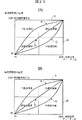
図23は既述のデューティと電圧制御の組み合わせによって駆動部電力を制御する場合の制御特性のパターン図を示したものである。(1)はモーターを加速制御する場合であり、モーターの指示速度と実速度との間に所定の速度差があるとした場合、限界デューティ比及び限界加速比が共に50%以上で急加速と成り得る領域となり、いずれかが50%未満の場合中加速となり得る領域となり、共に50%未満の場合は低加速となり得る領域となる。A−Cは図示する変化特性によって限界デューティ比と加速電圧比を変化させ、モーター(車両)を低加速領域―中加速領域―高加速領域の範囲で変化させることができる。Dは限界デューティ比を100%に固定して加速限界電圧比を変えた場合のモードであり、Eは仮想限界電圧比を100%にして加速限界デューティ比を変えた場合のモードである。(2)はモーターを減速させる場合の特性である。
図24は、図6のブロック図の一部に対する他の実施形態を詳細に示したものである。水晶発振回路62Aから基準比較周波数形成回路64そして位相比較器68に至る制御ブロックと、回転センサー42から位相比較器68に至る制御ブロックの詳細ブロックが示されている。
回転速度センサー42からの信号はPLL制御回路714によって後述の基準周波数信号と比較されるサンプリング信号に変換される。すなわち、ロータリエンコダー42の信号は位相比較器716に入力されて、電圧制御発振器718からの周波数信号が分周器720で1/FrN分周された周波数信号の位相と比較される。位相比較器716からの位相差検出信号はローパスフィルタ717を介して既述の電圧制御発振器718に供給される。電圧制御発振器718からの周波数信号は、N分周器70において分周される。この結果、ロータリエンコーダからのサンプリング信号から、後述の基準周波数信号と比較されるサンプリング周波数信号が作られる。
一方、水晶発振器62Aから発振周波数はM分周器722で1/M分周され位相比較器724に供給され、以後ローパスフィルタ726、電圧制御発振器728を経てN分周器730を経て前記位相比較器724に帰還される。PLL制御回路732によって周波数が一定となった基準周波数信号が位相比較器734に供給される。
既述のロータリエンコーダのサンプリング信号F1と基準周波数信号F2との位相差が前記位相比較器734で比較され、この位相差に基づいて、後輪を駆動させるステッピングモータ12の駆動制御装置(加減速制御装置)に制御信号が供給される。
マイクロコンピュータ60は、車両速度、或いは駆動輪の回転速度等種々の運転状況を表す値から前記M分周器722のM値、N分周器70,720のN値を設定する。すなわち、例えば車両の各速度において、基準周波数とサンプリング周波数と位相を一致させるM値及びN値を予めシミュレートしておきこれをマイクロコンピュータのメモリの所定領域にメモリテーブルの形で記憶させておき、車両の速度(目的速度或いは検出速度等)からこのM,N値を読み出し、前記PLL回路の分周器70,720,722,730のM又はN値として指定する。この実施形態によれば、ロータリーエンコーダの検出周波数を720で分周して増加させ、これをPLLブロック714で安定させることができ、この周波数を位相比較器68に供給するために、位相差信号を微細に得ることが可能となる。
PLL(Phase Locked Loop)回路は、位相を同期させるフィードバック制御回路であり、パルスや交流信号等の周波数を持つ信号を基準信号と同位相となるように出力の位相を制御するために用いられる。この技術は、情報処理機器のハードディスクを回転させるためのスピンドルモータや、ビデオデッキヘッドを回転させるためのモータ、レーザー走査するためのポリゴンミラーを回転させるためのモータ等に多用されており、対象モータは、ステッピングモータ等がほとんどであった。本発明では、一定の電圧で駆動するACモータやDCモータに対しても、インバーター制御をすることでモータの回転速度を制御可能とし、かつPLL技術を応用することで、精度よい転回角度制御が可能となる。特に、被駆動体の移動に対して負荷が変化するような場合、トルク制御が必要であるが、被駆動体の現速度を実測することで、トルク負荷を加味した状態での速度制御が可能となる。
以上説明した如く本発明では、オン・オフ制御でしか駆動させなかったモーターの回転速度を制御可能として、かつ指定された速度に駆動を補正することができ、また、速度制御をPLL回路によって達成し、安定した加速、減速が可能となる。
また、水晶発振器62Aからの周波数もPLL回路に出力されているために、水晶発振器の基本周波数を増加させ、かつ安定した周波数を発生することが可能となる。
【図面の簡単な説明】
図1は、本実施の形態に係る車両の平面図である。図2は、本実施の形態に係り、PLL回路を用いた自動速度制御のブロック図である。図3は、車両のインストルメントパネルの正面図である。図4は、本実施の形態に係るPLL制御による車両速度制御フローチャートである。図5は、指定速度を変化させた場合の、PLL制御による速度変化状態を示すタイムートである。図6は、前記駆動輪(後輪)を前進制御するためのブロック図である。図7は、位相比較器から出力される位相差信号のデューティを変化させるためのブロック図である。図8(1)は駆動制御回路のモーター駆動電圧印加回路の第1の実施形態であり、(2)はその第2の実施形態である。図9は駆動電圧印加制御のタイミング図である。図10は制動制御回路のブロック図及びその制御特性を示したものである。図11は駆動制御及び制動制御の際の位相差制御のタイミング図である。図12はモーター駆動・制動制御タイミングの波形図である。図13はモーター駆動制御の際のデューティ制御を説明するタイミング図である。図14には車輌(モーター)の加速度と限界デューティ比の関係が示す特性図である。図15は、駆動部制動制御の際のデューティ制御を説明するタイミング図である。図16に示すように、限界デューティ比と減速度との特性図である。図17は、モーターに印加される駆動電圧の限界電圧比を制御する場合のタイミング図である。図18は限界電圧比と車輌(モーター)との関係を示す特性図である。図19は、モーターの負荷電圧の制動負荷限界電圧比を制御する場合のタイミング図である。図20は制動負荷電圧比と車輌(モーター)との減速度との関係を示す特性図である。図21に車両速度−基準比較周波数特性の関係を示す。図22は、基準比較周波数が変更される場合のモーターの加速/制動のタイミング図である。図23は既述のデューティと電圧制御の組み合わせによって駆動部電力を制御する場合の制御特性のパターン図を示したものである。図24は図6のブロック図の一部に対する他の実施形態を詳細に示したものである。Technical field
The present invention relates to a drive control technique applied to a drive body including an electric drive unit. As this driving body, there is an electric traveling vehicle such as an electric vehicle, an electric wheelchair, an electric cart, etc., particularly including an electric motor as a driving unit. The drive control technology of the present invention can also be applied to a drive body constituting an electric construction machine, an electric welfare instrument, an electric robot, an electric toy, an electric airplane, an electric optical device such as a camera or a projector, or the like. The present invention can also be applied to home appliances such as air conditioners and fan motor heaters.
Background art
The electric travel vehicle travels when the drive control means controls the rotation of the electric motor. The drive control means adjusts the speed of the electric motor by adjusting the speed (rotational speed) of the electric motor. The speed adjustment is performed by changing the supply voltage supplied to the electric motor and controlling the power supplied to the electric motor. For example, when an occupant operates an accelerator pedal or a lever and acceleration is set in the drive control means based on the operation amount, the electric vehicle travels under the set acceleration. When the vehicle reaches a desired speed and the occupant returns the accelerator pedal or the accelerator lever to a predetermined level, the speed of the electric vehicle is maintained at a predetermined value.
On the other hand, when the vehicle is decelerated, the occupant sets the accelerator pedal or the accelerator lever at a position where the vehicle is decelerated. As a result, the drive control means performs braking control to decelerate the electric motor to a predetermined speed. When the operation state of the accelerator pedal or the accelerator lever is maintained, the vehicle speed is maintained at a predetermined value.
However, since the vehicle speed is adjusted by the driver, the vehicle speed is not constant depending on the condition of the road, for example, the slope of the road or the friction of the road surface, and the occupant frequently adjusts the vehicle speed. I had to do the accelerator operation.
Therefore, a technique called cruise control is provided. This technique is designed to maintain the vehicle speed at a specified speed even when a disturbance occurs in the vehicle speed.
In the case of an electric motor with high rotational speed control accuracy, such as a stepping motor, such speed control can be suitably realized, but in general AC motors and DC motors, it rotates when the power is turned on and rotates when the power is turned off. However, only a rough rotation control such as stopping is performed, and a technique for finely and accurately controlling the rotation speed of the motor has not yet been established.
In addition, if a speed change means such as a continuously variable transmission is used, the rotation speed of the wheel at the end can be accurately changed even if the rotation speed of the motor is constant, but the number of parts increases and the weight increases, so it is light and small. However, it is not suitable for small electric vehicles, electric wheelchairs, and passenger carts.
Further, the drive control means is constituted by a microcomputer. When the electric motor is in a high speed rotation state, the frequency of the detection signal from the electric motor is high, and the drive control processing in the computer is not in time. Therefore, there has been a problem that fine and quick control cannot be sufficiently performed for a high-speed electric motor.
Moreover, in order to release the loss in the power control as heat, the conversion efficiency in converting the power energy into the drive energy of the electric drive body is poor.
Therefore, an object of the present invention is to provide a drive control technique that can execute control sufficiently corresponding to high-speed operation of an electric drive unit. Another object of the present invention is to provide a drive control technique capable of accurately operating a drive unit in a designated operation state. Still another object of the present invention is to provide a drive control technique that can effectively use the braking power generated during the braking control of the drive unit. Still another object of the present invention is to use PLL control as the drive control technique. Still another object of the present invention is to provide a drive control technique for controlling the electric power of the electric drive unit based on the operation state of the electric drive unit in addition to the PLL control. Still another object of the present invention is to control the operation of the electric drive unit by changing the duty or voltage of the supply voltage to the electric drive unit. Another object of the present invention is to change the braking characteristics of the drive unit by controlling the braking power. Another object of the present invention is to provide a drive control device and a drive control method provided with this drive control technique. Still another object of the present invention is to provide a drive body, particularly an electric vehicle, which is controlled by this drive control technique.
Summary of the Invention
In order to achieve the above object, the present invention provides a drive control apparatus for controlling an electric rotation drive unit for moving a drive body, and detects a reference comparison signal generation circuit and the speed of the drive unit, and detects the detected signal. The detection circuit that outputs the output signal, the speed instruction circuit of the drive unit, the rotation control circuit of the drive unit, the phase of the reference comparison signal and the phase of the detection signal are compared, and the comparison result is sent to the rotation control circuit. And a phase comparison circuit for outputting, wherein the rotation control circuit controls the speed of the drive unit to match the speed instruction based on the phase comparison result.
In the embodiment of the present invention, the drive control device is configured as follows. The reference comparison signal generation circuit, the detection circuit, and the phase comparison circuit constitute a PLL control block. The phase comparison circuit outputs a phase difference signal to the rotation control circuit, and the rotation control circuit outputs the phase difference signal to the drive unit.
The rotation control circuit distinguishes from the phase difference signal whether the drive unit is in an acceleration operation state or a braking operation state, and controls the drive unit based on the result.
The rotation control circuit includes a drive control circuit that accelerates the drive unit and a brake control circuit that brakes the drive unit. The rotation control circuit includes characteristic changing means for changing the power characteristic of the driving unit. The characteristic changing means changes the duty of the driving unit power. The characteristic changing means changes a limit value of the driving unit power. The characteristic changing means changes the duty of the drive unit power in accordance with the duty of the phase difference signal.
The characteristic changing means sets a limit change ratio of the duty. A power storage unit capable of storing the braking power of the drive unit is provided as a load of the braking control circuit. The braking control circuit intermittently controls the power storage unit and the drive unit based on the phase difference signal. The characteristic changing means changes the duty of the load power of the driving unit.
The characteristic changing means changes the power limit value of the load power of the drive unit. The characteristic changing means changes the duty of the power supplied to the driving unit. The characteristic changing means changes a limit value of power supplied to the driving unit. The characteristic changing means changes the duty of the drive unit power and its limit value. The drive control circuit intermittently controls the drive voltage supplied to the drive unit based on the duty of the phase difference signal. The reference comparison signal generation circuit divides the fundamental frequency and outputs a reference comparison signal, and the rotation control circuit changes the division ratio in accordance with an instruction value of the speed instruction circuit.
The detection circuit divides the detection value from the rotation sensor of the drive unit and outputs it as the detection signal, and the rotation control circuit changes the division ratio according to the instruction value of the speed instruction circuit. Let The characteristic changing means changes the power characteristic in accordance with an operating state of the drive unit. The characteristic changing means changes the power characteristic according to the operating state of the driving body. The characteristic changing means changes the power characteristic when the drive unit is in an acceleration or braking transition region.
The present invention also includes a drive body that includes a drive control device and an electric drive unit that is driven and controlled by the drive control device. The present invention also includes an electric traveling vehicle including a drive control device and an electric drive unit that is driven and controlled by the drive control device.
The drive control method of the present invention is a drive control method for controlling an electric rotary drive unit for moving a drive body, and detects a reference comparison signal generation step and the speed of the drive unit, and outputs this as a detection signal. A phase comparison result comprising: a detection step; a speed instruction step of the drive unit; a rotation control step of the drive unit; and a phase comparison step of comparing the phase of the reference comparison signal with the phase of the detection signal. Based on the control, the speed of the drive unit is controlled to match the speed instruction.
Preferred embodiments for carrying out the invention
FIG. 1 shows an
The
On the other hand, each of the rear wheels 16 </ b> B is connected to the
FIG. 2 shows a functional diagram of the
The frequency signal N is input from the designated
The
The
This frequency signal S is input to the
The
Therefore, by executing the control so that the phases of the frequency signal M and the frequency signal N coincide with each other as described above, the rotation of the rear wheels is controlled so that the vehicle speed is controlled to converge to the indicated speed. The According to the above-described control configuration, the control of the rotational speed of the rear wheel is accurate and easily and quickly performed by the PLL control method.
FIG. 3 shows an
The
Further, the
Further, by continuing to operate the
The flow for motor drive control will be described below with reference to the flowchart of FIG. 4 and the time chart of FIG.
First, in
In
In
If it is determined in
In the
Here, when there is a change in the instruction speed in
When the
Next, the control from the
Although an example in which the
When the speed instruction value is increased, the set frequency N is first increased accordingly, and the PLL control frequency M is increased so as to follow this (region in which the frequency vector is upward). Further, when the vehicle speed instruction value is lowered, first, the set frequency N is lowered, and the PLL control frequency M is lowered so as to follow this (frequency vector is a downward region). Further, when the speed is maintained, the set frequency N and the PLL control frequency M coincide (region where the frequency vector is horizontal). Based on the phase difference between the frequency signals N and M, the above-described control is realized by the PLL control method.
As described above, in this embodiment, the frequency phase comparison control by the PLL circuit is used for the speed control of the
In the present embodiment, the
As such a non-contact type speed measuring device, a known device that is applied to a technique for detecting a moving speed of a mouse of a personal computer or a hitting speed in baseball or golf can be widely applied (for example, Japanese Patent Laid-Open No. Hei. 6-313749 and 7-134139).
By using such a non-contact type sensor, for example, it is possible to prevent erroneous speed detection during idling when the
Further, when the
Next, another embodiment of the drive control apparatus according to the present invention will be described. FIG. 6 is a block diagram for forwardly controlling the drive wheel (rear wheel). (1) is a control block diagram when the motor is accelerated, and (2) is a block diagram when the motor is brake-controlled.
The
In the case where the rotation direction of the motor is a direction in which the vehicle is moved backward, the control block is the same as that in FIG. 6 except that the polarities of the drive current and the braking current are different.
When the
As described above, the
One method for changing the power characteristic value is to use a phase difference signal (UP / DOWN) output from the
FIG. 7 is a block diagram for changing the duty of the phase difference signal output from the
FIG. 8A is a first embodiment of a motor drive voltage application circuit of the
A phase difference signal (UP) is input from the
The DC /
The
FIG. 8B is a second example of the drive voltage control circuit. This control circuit includes a
The detection signal from the rotation sensor divided by the
FIG. 9 is a timing chart of the drive voltage application control described in FIG. (1) is the waveform of the fundamental frequency signal from the crystal oscillator. (2) is a waveform of an output pulse from the
FIG. 10A shows a block diagram of the
The DOWN signal described above is input from the
FIG. 10 (2) is a characteristic diagram showing the relationship between the number of rotations of the motor and the power generated in the power converter. As the rotation speed of the motor increases, the power output value of the power converter increases. (3) is a characteristic diagram showing the relationship between the rotational speed of the motor and the output voltage value of the power converter, and the charging
The power characteristic of the load power (braking power) of the braking control circuit can be changed by changing the duty of the load power or changing the voltage (charge voltage) of the load power. The duty of the load power is changed by the duty of the phase difference signal (DOWN) supplied to the
FIG. 11 is a timing diagram of phase difference control during drive control and braking control. (A) is a reference frequency signal oscillated from the fundamental
(G) is the timing of the voltage (vehicle forward side) applied from the drive control circuit to the motor, and (H) is the timing of the voltage (vehicle backward side) applied from the drive control circuit to the motor.
FIG. 12 (1) is a waveform diagram of motor drive control timing, and FIG. 12 (2) is a waveform diagram of brake control timing, explaining FIG. 11 in more detail. In (1), the
In the transition region (acceleration period) where the motor starts to reach the indicated speed, the phase difference signal is output long, and when the actual speed of the motor reaches the indicated speed, the phase difference signal output period decreases. When the acceleration stabilization period is reached, the motor reaches the indicated speed. When the motor speed exceeds the command speed during the acceleration stabilization period, a phase difference signal (DOWN) is supplied to the
(2) is different from (1) in that a deceleration instruction is supplied to the motor. The deceleration period is a period during which the motor is decelerated to the designated speed, and a phase difference signal (DOWN) in the motor deceleration direction is supplied to the
FIG. 13 is a timing diagram illustrating duty control during motor drive control. (A) shows that the limit duty ratio set in the limit duty
FIG. 14 shows the relationship between the acceleration of the vehicle (motor) and the limit duty ratio, and the acceleration decreases as the limit duty ratio decreases. That is, when the duty of the drive voltage is 50% as shown in (C), the acceleration is almost ½ compared to the limit duty ratio of 100%, and in the case of (B) compared to the case of (A). The vehicle speed (rotational speed of the motor) is approximately doubled to reach the desired command speed.
Next, the relationship between the driving state of the vehicle (drive unit) and the limit duty ratio will be described. The first is a high duty ratio mode. For example, (1) when the electric vehicle is in a low speed running state, (2) when the electric vehicle is in a straight running state, (3) when the electric vehicle is running on a public road, (4) road surface condition When the motor is in a high friction state, it is possible to allow the motor to accelerate rapidly. At this time, a duty (drive voltage) having a value obtained by multiplying the duty of the phase difference signal of the phase comparison unit by the high duty ratio is output to the drive circuit. As a result, the acceleration instruction to the motor is transmitted to the motor almost as it is.
The second is the medium duty ratio mode. For example, when an electric vehicle is in a turning state where (1) R is relatively large, (2) when the electric vehicle is traveling in a speed-limited site, (3) the road surface state is slightly wet This is a mode when it is necessary to limit the acceleration instruction to the motor at a certain time.
The third is a low duty ratio mode. For example, (1) when the electric vehicle is in a high speed state, (2) when the electric vehicle is in a turning state with a small R, (3) when the electric vehicle is traveling in a building, (4) when the road surface is wet This mode is used when it is necessary to greatly limit the acceleration instruction to the motor, etc.
The duty ratio may be set by an occupant, or the
FIG. 15 is a timing chart for explaining the duty control at the time of driving unit braking control. When braking control of the drive unit, the
Assume that the operation system of the electric vehicle is configured as follows, for example. When the occupant removes his / her leg from the accelerator pedal, the computer determines that there has been a deceleration instruction and determines a predetermined deceleration instruction speed. Next, the limit duty ratio is set in the
A brake pedal is also provided on the vehicle. When the occupant steps on the brake pedal, the computer determines a mode in which the vehicle should be braked according to the amount of depression of the brake pedal. In the case of sudden braking, a high duty ratio is set. When a drum brake or a disc brake is used together and the amount of depression of the brake is large, these mechanical brakes may be operated to assist the electric power generation brake.
Next, control of the limit voltage ratio will be described. FIG. 17 is a timing chart for controlling the limit voltage ratio of the drive voltage applied to the motor. The
FIG. 19 is a timing chart for controlling the braking load limit voltage ratio of the motor load voltage. As described above, the change of the load voltage is achieved by voltage control of the power conversion unit by the charging
Next, FIG. 21 shows the relationship between vehicle speed and reference comparison frequency characteristics. The reference comparison frequency increases as the speed increases. The reference comparison frequency can be increased, for example, by changing the M value of the M frequency divider. As the frequency of the reference comparison signal increases, the frequency of occurrence of a phase difference from the detection signal increases, and the speed control can be performed more finely in the high speed region.
(A) of FIG. 22 (1) is a waveform diagram when the motor is accelerated and shows that the reference comparison frequency increases as the rotational speed of the motor increases. (B) is a phase difference signal output to the
FIG. 23 shows a pattern diagram of control characteristics in the case where the drive unit power is controlled by the combination of the aforementioned duty and voltage control. (1) is a case where the motor is controlled to be accelerated. If there is a predetermined speed difference between the command speed of the motor and the actual speed, the critical duty ratio and the critical acceleration ratio are both 50% or more, and sudden acceleration This is a region that can be achieved, and if either is less than 50%, it becomes a region that can be accelerated, and if both are less than 50%, it becomes a region that can become low acceleration. AC can change the limit duty ratio and the acceleration voltage ratio according to the change characteristics shown in the figure, and can change the motor (vehicle) in the range of the low acceleration region-medium acceleration region-high acceleration region. D is a mode in which the limit duty ratio is fixed to 100% and the acceleration limit voltage ratio is changed, and E is a mode in which the acceleration limit duty ratio is changed by setting the virtual limit voltage ratio to 100%. (2) is a characteristic when the motor is decelerated.
FIG. 24 shows another embodiment in detail for a portion of the block diagram of FIG. A detailed block of a control block from the
A signal from the
On the other hand, the oscillation frequency from the
The phase difference between the sampling signal F1 of the rotary encoder described above and the reference frequency signal F2 is compared by the phase comparator 734, and based on this phase difference, the drive control device (acceleration / deceleration) of the stepping
The
A PLL (Phase Locked Loop) circuit is a feedback control circuit for synchronizing phases, and is used to control the phase of an output so that a signal having a frequency such as a pulse or an AC signal has the same phase as a reference signal. This technology is widely used in spindle motors for rotating hard disks of information processing equipment, motors for rotating video deck heads, motors for rotating polygon mirrors for laser scanning, etc. Most of them were stepping motors. In the present invention, it is possible to control the rotational speed of an AC motor or DC motor driven by a constant voltage by controlling the inverter, and by applying the PLL technology, it is possible to control the turning angle with high accuracy. It becomes possible. In particular, torque control is necessary when the load changes with the movement of the driven body, but speed control with the torque load taken into account is possible by measuring the current speed of the driven body. It becomes.
As described above, in the present invention, it is possible to control the rotational speed of the motor that was driven only by the on / off control, and the drive can be corrected to the designated speed, and the speed control is achieved by the PLL circuit. Stable acceleration and deceleration are possible.
In addition, since the frequency from the
[Brief description of the drawings]
FIG. 1 is a plan view of the vehicle according to the present embodiment. FIG. 2 is a block diagram of automatic speed control using a PLL circuit according to the present embodiment. FIG. 3 is a front view of the instrument panel of the vehicle. FIG. 4 is a vehicle speed control flowchart based on PLL control according to the present embodiment. FIG. 5 is a time chart showing a speed change state by PLL control when the designated speed is changed. FIG. 6 is a block diagram for forwardly controlling the drive wheel (rear wheel). FIG. 7 is a block diagram for changing the duty of the phase difference signal output from the phase comparator. FIG. 8 (1) is a first embodiment of a motor drive voltage application circuit of the drive control circuit, and (2) is the second embodiment. FIG. 9 is a timing chart of drive voltage application control. FIG. 10 is a block diagram of the braking control circuit and its control characteristics. FIG. 11 is a timing diagram of phase difference control during drive control and braking control. FIG. 12 is a waveform diagram of motor drive / brake control timing. FIG. 13 is a timing diagram illustrating duty control during motor drive control. FIG. 14 is a characteristic diagram showing the relationship between the acceleration of the vehicle (motor) and the limit duty ratio. FIG. 15 is a timing chart for explaining the duty control at the time of driving unit braking control. As shown in FIG. 16, it is a characteristic diagram of a limit duty ratio and deceleration. FIG. 17 is a timing chart for controlling the limit voltage ratio of the drive voltage applied to the motor. FIG. 18 is a characteristic diagram showing the relationship between the limit voltage ratio and the vehicle (motor). FIG. 19 is a timing chart for controlling the braking load limit voltage ratio of the motor load voltage. FIG. 20 is a characteristic diagram showing the relationship between the braking load voltage ratio and the deceleration of the vehicle (motor). FIG. 21 shows the relationship between the vehicle speed and the reference comparison frequency characteristic. FIG. 22 is a timing diagram of motor acceleration / braking when the reference comparison frequency is changed. FIG. 23 shows a pattern diagram of control characteristics in the case where the drive unit power is controlled by the combination of the aforementioned duty and voltage control. FIG. 24 shows another embodiment in detail for a part of the block diagram of FIG.
Claims (9)
前記モータ駆動部を制御する制御部と、を備えたモータ駆動装置であって、A motor drive device comprising a control unit for controlling the motor drive unit,
前記制御部は、The controller is
基準周波数信号を生成する基準信号生成回路と、A reference signal generation circuit for generating a reference frequency signal;
前記モータの回転速度を設定する回転速度設定回路と、A rotation speed setting circuit for setting the rotation speed of the motor;
前記モータの実際の回転速度を検出し、検出周波数信号を出力する検出回路と、A detection circuit that detects an actual rotation speed of the motor and outputs a detection frequency signal;
前記基準周波数信号の位相と、前記検出周波数信号から算出された周波数信号の位相とを比較し、これらの周波数信号間の位相差を計算し、前記計算された位相差に基づき位相差信号を出力する比較回路と、Compare the phase of the reference frequency signal with the phase of the frequency signal calculated from the detected frequency signal, calculate the phase difference between these frequency signals, and output the phase difference signal based on the calculated phase difference A comparison circuit to
前記モータ駆動部が、当該モータ駆動部から前記モータへ出力する前記駆動信号を前記位相差信号に基づき変更するように、前記モータ駆動部へ制御信号を出力する制御信号出力回路と、A control signal output circuit for outputting a control signal to the motor drive unit so that the motor drive unit changes the drive signal output from the motor drive unit to the motor based on the phase difference signal;
前記検出周波数信号の周波数を分周する分周率を、前記回転速度設定回路により設定された前記モータ回転速度に基づき設定し、当該設定された分周率を、前記基準周波数信号と前記分周率によって分周された前記検出周波数信号との間の位相差を求めるために前記比較回路により行われる前記計算に適用する分周回路と、A frequency division ratio for dividing the frequency of the detection frequency signal is set based on the motor rotation speed set by the rotation speed setting circuit, and the set frequency division ratio is set to the reference frequency signal and the frequency division. A frequency dividing circuit applied to the calculation performed by the comparison circuit to determine a phase difference between the detection frequency signal divided by a rate;
を備える、モータ制御装置。A motor control device.
前記分周回路は、前記基本信号の周波数を分周するための第2の分周率を設定する基本信号分周回路を備え、The frequency dividing circuit includes a basic signal frequency dividing circuit that sets a second frequency dividing rate for dividing the frequency of the basic signal,
前記基準信号生成回路は、分周された信号を基準信号として前記比較回路に出力する出力回路を備える、The reference signal generation circuit includes an output circuit that outputs the divided signal as a reference signal to the comparison circuit.
請求項1に記載のモータ制御装置。The motor control device according to claim 1.
前記制御信号出力回路は、前記位相差信号に基づき、前記駆動制御回路または前記制動制御回路へ前記制御信号を供給する、The control signal output circuit supplies the control signal to the drive control circuit or the braking control circuit based on the phase difference signal.
請求項1に記載のモータ制御装置。The motor control device according to claim 1.
請求項4に記載のモータ制御装置。The motor control device according to claim 4.
請求項1、4、または5に記載のモータ制御装置。The motor control device according to claim 1, 4 or 5.
前記モータ制御装置に制御されるモータと、A motor controlled by the motor control device;
前記モータに接続される駆動部と、A drive unit connected to the motor;
を備えることを特徴とする車両。A vehicle comprising:
Applications Claiming Priority (5)
| Application Number | Priority Date | Filing Date | Title |
|---|---|---|---|
| JP2001123411 | 2001-04-20 | ||
| JP2001123411 | 2001-04-20 | ||
| JP2001123412 | 2001-04-20 | ||
| JP2001123412 | 2001-04-20 | ||
| PCT/JP2002/003998 WO2002087066A1 (en) | 2001-04-20 | 2002-04-22 | Drive control |
Publications (2)
| Publication Number | Publication Date |
|---|---|
| JPWO2002087066A1 JPWO2002087066A1 (en) | 2004-08-12 |
| JP4178955B2 true JP4178955B2 (en) | 2008-11-12 |
Family
ID=26613955
Family Applications (2)
| Application Number | Title | Priority Date | Filing Date |
|---|---|---|---|
| JP2002584465A Expired - Fee Related JP4178955B2 (en) | 2001-04-20 | 2002-04-22 | Drive control |
| JP2002583215A Expired - Fee Related JP4193496B2 (en) | 2001-04-20 | 2002-04-22 | Drive control device to be controlled |
Family Applications After (1)
| Application Number | Title | Priority Date | Filing Date |
|---|---|---|---|
| JP2002583215A Expired - Fee Related JP4193496B2 (en) | 2001-04-20 | 2002-04-22 | Drive control device to be controlled |
Country Status (5)
| Country | Link |
|---|---|
| US (2) | US6988570B2 (en) |
| JP (2) | JP4178955B2 (en) |
| KR (2) | KR100499904B1 (en) |
| DE (2) | DE10296667T5 (en) |
| WO (2) | WO2002085663A1 (en) |
Families Citing this family (72)
| Publication number | Priority date | Publication date | Assignee | Title |
|---|---|---|---|---|
| US7090040B2 (en) * | 1993-02-24 | 2006-08-15 | Deka Products Limited Partnership | Motion control of a transporter |
| US7674245B2 (en) | 2001-06-07 | 2010-03-09 | Cardiac Pacemakers, Inc. | Method and apparatus for an adjustable shape guide catheter |
| US7717899B2 (en) | 2002-01-28 | 2010-05-18 | Cardiac Pacemakers, Inc. | Inner and outer telescoping catheter delivery system |
| US7075261B2 (en) * | 2002-04-10 | 2006-07-11 | Standard Microsystems Corporation | Method and apparatus for controlling a fan |
| US20040039371A1 (en) * | 2002-08-23 | 2004-02-26 | Bruce Tockman | Coronary vein navigator |
| DE10305368A1 (en) * | 2003-02-10 | 2004-08-19 | Siemens Ag | Electrical machine with temperature monitoring especially for large electrical machines, uses thermal radiation sensors for contactless detection of radiant heat |
| EP1466775A3 (en) * | 2003-04-10 | 2010-09-15 | Nissan Motor Company Limited | Drive controlling apparatus and method for automotive vehicle |
| US6911794B2 (en) * | 2003-05-08 | 2005-06-28 | Wavecrest Laboratories, Llc | Precision adaptive motor control in cruise control system having various motor control schemes |
| AU2003241153A1 (en) | 2003-05-26 | 2004-12-13 | I.S.A.L. S.R.L. | Self-propelled sweeper with electric steering and relative control system |
| DE10324812A1 (en) * | 2003-06-02 | 2004-12-23 | Robert Bosch Gmbh | Display arrangement for a motor vehicle and method for outputting driver information, in particular for a parking aid |
| JP4173121B2 (en) * | 2003-09-02 | 2008-10-29 | 株式会社小松製作所 | Construction machine operation system |
| US7920725B2 (en) * | 2003-09-09 | 2011-04-05 | Fujifilm Corporation | Apparatus, method, and program for discriminating subjects |
| US7865275B2 (en) * | 2003-10-10 | 2011-01-04 | Dynamic Controls Limited | Method and apparatus for controlling an electric vehicle function |
| US7017327B2 (en) * | 2003-12-10 | 2006-03-28 | Deere & Company | Hybrid electric tool carrier |
| US20050206226A1 (en) * | 2004-03-18 | 2005-09-22 | Ford Global Technologies, Llc | Method and apparatus for controlling an automotive vehicle in a u-turn |
| US20050206231A1 (en) * | 2004-03-18 | 2005-09-22 | Ford Global Technologies, Llc | Method and apparatus for controlling an automotive vehicle using brake-steer and normal load adjustment |
| US7165644B2 (en) * | 2004-03-18 | 2007-01-23 | Ford Global Technologies, Llc | Method and apparatus of controlling an automotive vehicle using brake-steer as a function of steering wheel torque |
| US8380416B2 (en) | 2004-03-18 | 2013-02-19 | Ford Global Technologies | Method and apparatus for controlling brake-steer in an automotive vehicle in reverse |
| US20050236208A1 (en) * | 2004-04-27 | 2005-10-27 | Richard Runkles | Power wheelchair |
| US8925659B2 (en) * | 2004-05-07 | 2015-01-06 | Charles E. Wilson | Electric utility vehicle |
| JP3968785B2 (en) | 2004-05-18 | 2007-08-29 | セイコーエプソン株式会社 | Drive regeneration control system |
| WO2005110801A1 (en) * | 2004-05-19 | 2005-11-24 | Mitsubishi Denki Kabushiki Kaisha | Electric vehicle controller |
| JP4127251B2 (en) * | 2004-07-23 | 2008-07-30 | 株式会社デンソー | DC motor rotation information detector |
| US7325636B2 (en) * | 2004-08-30 | 2008-02-05 | Caterpillar Inc. | Front-wheel drive steering compensation method and system |
| JP4380491B2 (en) * | 2004-09-30 | 2009-12-09 | ブラザー工業株式会社 | Rotation drive evaluation apparatus and method, correction operation amount setting apparatus and method, control apparatus and method, and program |
| JP2006109547A (en) * | 2004-09-30 | 2006-04-20 | Sanyo Electric Co Ltd | Electric vehicle and electric vehicle driving control program |
| JP4448759B2 (en) * | 2004-11-09 | 2010-04-14 | 本田技研工業株式会社 | Driving control method of self-propelled cart |
| DE102005006574B3 (en) * | 2005-02-11 | 2006-09-21 | Barthelt, Hans-Peter, Dipl.-Ing. | Wheelchair with remote control |
| US7275975B2 (en) * | 2005-06-03 | 2007-10-02 | Mattel, Inc. | Toy vehicle with on-board electronics |
| US20070114742A1 (en) * | 2005-07-29 | 2007-05-24 | Gilbert Roger A | Motorized carts for stepping structures |
| JP2007221974A (en) * | 2006-02-20 | 2007-08-30 | Rohm Co Ltd | Stepping motor drive and method and electronic equipment using them |
| JP2007252153A (en) * | 2006-03-20 | 2007-09-27 | Hitachi Ltd | Automobile controller and automobile |
| US7583037B2 (en) | 2006-06-23 | 2009-09-01 | Spacesaver Corporation | Mobile storage unit with holding brake and single status line for load and drive detection |
| JP4857952B2 (en) * | 2006-06-28 | 2012-01-18 | 株式会社日立製作所 | Electric drive vehicle |
| WO2008005886A2 (en) * | 2006-07-07 | 2008-01-10 | Hydro-Gear Limited Partnership | Electronic steering control apparatus |
| US8950520B2 (en) * | 2006-07-07 | 2015-02-10 | Hydro-Gear Limited Partnership | Front steering module for a zero turn radius vehicle |
| EP1943894B1 (en) * | 2007-01-15 | 2010-05-19 | Kanzaki Kokyukoki Mfg. Co., Ltd. | Riding lawn mower |
| US7648002B2 (en) * | 2007-06-08 | 2010-01-19 | Deere & Company | Vehicle with coordinated Ackerman and differential steering |
| JP2009219345A (en) | 2008-02-15 | 2009-09-24 | Seiko Epson Corp | Power generator and motor device |
| US7863849B2 (en) * | 2008-02-29 | 2011-01-04 | Standard Microsystems Corporation | Delta-sigma modulator for a fan driver |
| US8118417B2 (en) * | 2008-03-06 | 2012-02-21 | Xerox Corporation | System and method for processing solid ink stick exception conditions in a solid ink printer |
| JP5309656B2 (en) * | 2008-04-01 | 2013-10-09 | セイコーエプソン株式会社 | Motor control circuit and moving body provided with motor control circuit |
| TWI380576B (en) * | 2008-05-23 | 2012-12-21 | Delta Electronics Inc | Motor control apparatus and method thereof |
| US20100082180A1 (en) * | 2008-10-01 | 2010-04-01 | Honeywell International Inc. | Errant vehicle countermeasures |
| US8241008B2 (en) * | 2009-02-26 | 2012-08-14 | Standard Microsystems Corporation | RPM controller using drive profiles |
| TWI392214B (en) * | 2009-06-04 | 2013-04-01 | Univ Nat Chiao Tung | The driving device and driving method of multi - phase straight / AC converter |
| EP2444301B1 (en) * | 2009-06-19 | 2014-03-26 | National University Corporation Toyohashi University of Technology | Steerable drive mechanism and omnidirectional moving vehicle |
| US8137152B2 (en) * | 2010-05-25 | 2012-03-20 | Fun Tram Corporation | Remote control ball assembly |
| CN103019236B (en) * | 2011-09-26 | 2015-07-08 | 东莞易步机器人有限公司 | Two-wheel car self-support running method |
| EP2807407B1 (en) * | 2012-01-25 | 2016-01-06 | Crown Equipment Corporation | System and method for monitoring state of function of a materials handling vehicle |
| KR101328422B1 (en) | 2012-04-12 | 2013-11-14 | (주)엠피에스코리아 | An Electric Vehicle |
| WO2013190821A1 (en) * | 2012-06-19 | 2013-12-27 | 住友重機械工業株式会社 | Motor driving device for forklifts and forklifts using same |
| KR101387221B1 (en) | 2012-11-30 | 2014-04-21 | 삼성전기주식회사 | System and method for controlling speed of motor |
| JP6259236B2 (en) * | 2013-09-24 | 2018-01-10 | ローム株式会社 | Motor drive device |
| US9260092B1 (en) | 2013-09-27 | 2016-02-16 | Google Inc. | Methods and systems for steering-based oscillatory vehicle braking |
| JP6263970B2 (en) * | 2013-11-11 | 2018-01-24 | 村田機械株式会社 | Data structure of autonomous traveling vehicle and planned traveling route data |
| US9098079B2 (en) | 2013-12-13 | 2015-08-04 | King Fahd University Of Petroleum And Minerals | Method of joint planning and control of a rigid, separable non-holonomic mobile robot using a harmonic potential field approach |
| JP6113365B2 (en) * | 2014-06-30 | 2017-04-12 | エスゼット ディージェイアイ テクノロジー カンパニー リミテッドSz Dji Technology Co.,Ltd | Method and apparatus for adjusting pan head parameter and pan head device |
| US10183694B1 (en) * | 2014-08-28 | 2019-01-22 | Hydro-Gear Limited Partnership | Electric transaxle with integral power generating device |
| EP3233180B1 (en) * | 2014-12-18 | 2020-01-29 | Cardiac Pacemakers, Inc. | Fibrous joinery interface between structures |
| US10836426B1 (en) * | 2015-04-06 | 2020-11-17 | Exmark Manufacturing Company, Incorporated | Active steering system and grounds maintenance vehicle including same |
| GB201513549D0 (en) * | 2015-07-31 | 2015-09-16 | Siemens Ag | Inverter |
| US11031900B2 (en) * | 2016-04-27 | 2021-06-08 | Mitsubishi Electric Corporation | Motor drive apparatus, refrigeration cycle apparatus and air conditioner |
| US10502574B2 (en) | 2016-09-20 | 2019-12-10 | Waymo Llc | Devices and methods for a sensor platform of a vehicle |
| US10277084B1 (en) | 2016-10-19 | 2019-04-30 | Waymo Llc | Planar rotary transformer |
| US10864127B1 (en) * | 2017-05-09 | 2020-12-15 | Pride Mobility Products Corporation | System and method for correcting steering of a vehicle |
| KR101939474B1 (en) * | 2017-07-07 | 2019-01-16 | 엘지전자 주식회사 | Motor drive apparatus |
| US11303240B2 (en) * | 2018-07-03 | 2022-04-12 | Kubota Corporation | Traveling control device |
| EP3821692A4 (en) | 2018-09-27 | 2021-08-25 | Nanjing Chervon Industry Co., Ltd. | Lawnmower |
| CN210610343U (en) | 2018-09-27 | 2020-05-26 | 南京德朔实业有限公司 | Lawn mower and blade assembly suitable for lawn mower |
| USD995569S1 (en) | 2019-04-18 | 2023-08-15 | Nanjing Chervon Industry Co., Ltd. | Mower blade assembly |
| JP2022115571A (en) * | 2021-01-28 | 2022-08-09 | スズキ株式会社 | small electric vehicle |
Family Cites Families (43)
| Publication number | Priority date | Publication date | Assignee | Title |
|---|---|---|---|---|
| US3697158A (en) * | 1970-09-28 | 1972-10-10 | Bell & Howell Co | Sound-on-film recording system |
| US3648141A (en) * | 1971-03-11 | 1972-03-07 | Honeywell Inc | Tape drive error-cancelling system |
| US3828234A (en) * | 1973-05-14 | 1974-08-06 | Rca Corp | Motor speed control system |
| US3883785A (en) * | 1973-09-27 | 1975-05-13 | Nasa | Low speed phaselock speed control system |
| FR2486881A1 (en) * | 1980-07-18 | 1982-01-22 | Jarret Jean | TERRESTRIAL VEHICLE WITH ELECTRONIC CONTROL AND DRIVING METHOD THEREFOR |
| JPS5859876A (en) * | 1981-10-07 | 1983-04-09 | Seiko Epson Corp | Carriage controller for serial printer using dc motor |
| US4471273A (en) * | 1983-01-05 | 1984-09-11 | Towmotor Corporation | Dual-motor control apparatus |
| DE3335776A1 (en) * | 1983-10-01 | 1985-04-18 | M.A.N. Maschinenfabrik Augsburg-Nürnberg AG, 8000 München | DEVICE FOR GUIDING A RAILWAY VEHICLE |
| US4520299A (en) * | 1983-12-22 | 1985-05-28 | General Electric Company | Turning speed controller for electric vehicles having dual drive motors |
| JPS60237380A (en) * | 1984-05-11 | 1985-11-26 | Nissan Motor Co Ltd | Phase tracking apparatus for loran c signal |
| US4817000A (en) * | 1986-03-10 | 1989-03-28 | Si Handling Systems, Inc. | Automatic guided vehicle system |
| US4825132A (en) * | 1987-05-21 | 1989-04-25 | Eaton Corporation | Current mode motor control |
| JP2764723B2 (en) * | 1988-01-06 | 1998-06-11 | 株式会社日立製作所 | Electric car control device |
| JP2504120B2 (en) * | 1988-06-03 | 1996-06-05 | 株式会社豊田自動織機製作所 | Manual steering control method for unmanned vehicles |
| WO1990011905A1 (en) * | 1989-03-31 | 1990-10-18 | Kabushiki Kaisha Shikoku Sogo Kenkyujo | Electric car |
| JP2984724B2 (en) * | 1989-03-31 | 1999-11-29 | 株式会社 四国総合研究所 | Electric car |
| JPH0756717B2 (en) * | 1990-01-26 | 1995-06-14 | ローム株式会社 | Phase control circuit |
| DE4192435C1 (en) * | 1990-10-03 | 2002-08-29 | Hitachi Ltd | Control for electric vehicle |
| JPH05176418A (en) * | 1991-03-25 | 1993-07-13 | Hitachi Ltd | Controller for electric automobile |
| JP3280392B2 (en) * | 1991-04-01 | 2002-05-13 | アイシン・エィ・ダブリュ株式会社 | Driving force control device for electric vehicle |
| US5258912A (en) * | 1991-06-24 | 1993-11-02 | General Motors Corporation | Wheel understeer speed control |
| DE4134240C2 (en) * | 1991-10-16 | 1995-12-14 | Mannesmann Ag | Steering support for a non-track-bound vehicle |
| US5379223A (en) * | 1992-06-19 | 1995-01-03 | Alliedsignal Inc. | Inertial measurement and navigation system using digital signal processing techniques |
| US5609220A (en) * | 1992-08-27 | 1997-03-11 | Kabushiki Kaisha Komatsu Seisakusho | Operation control system for traveling vehicle |
| KR0145431B1 (en) * | 1992-10-14 | 1998-08-01 | 마스다 쇼오이치로오 | Wheel supporter of moving car |
| US5456332A (en) * | 1992-11-10 | 1995-10-10 | The Board Of Regents Of The University Of Michigan | Multiple-degree-of-freedom vehicle |
| US5487437A (en) * | 1994-03-07 | 1996-01-30 | Avitan; Isaac | Coupled differential turning control system for electric vehicle traction motors |
| JPH0819110A (en) * | 1994-06-28 | 1996-01-19 | Motor Jidosha Kk | Driver for electric motor vehicle |
| US5670854A (en) * | 1994-12-14 | 1997-09-23 | Matsushita Electric Industrial Co., Ltd. | Control system for an induction motor |
| JP3451848B2 (en) * | 1996-09-10 | 2003-09-29 | トヨタ自動車株式会社 | Drive control device for electric vehicle |
| US5921338A (en) * | 1997-08-11 | 1999-07-13 | Robin L. Edmondson | Personal transporter having multiple independent wheel drive |
| DE19813945C2 (en) * | 1998-03-28 | 2000-02-03 | Daimler Chrysler Ag | Control device for influencing the driving dynamics of a four-wheel vehicle |
| US6353408B1 (en) * | 1998-03-31 | 2002-03-05 | U.S. Philips Corporation | Electronic navigation apparatus |
| DE19819956A1 (en) * | 1998-05-05 | 1999-11-11 | Heidelberger Druckmasch Ag | Device for speed control |
| JP4244412B2 (en) * | 1998-09-30 | 2009-03-25 | アイシン精機株式会社 | Motor rotation pulse generation circuit for DC motor and pinching detection device using the circuit |
| KR100338460B1 (en) * | 1999-01-22 | 2002-05-30 | 조동일 | Vehicle Detector Using Loop Sensor |
| WO2000046063A1 (en) * | 1999-02-08 | 2000-08-10 | Toyota Jidosha Kabushiki Kaisha | Vehicle braked by motor torque and method of controlling the vehicle |
| JP2000261914A (en) * | 1999-03-10 | 2000-09-22 | Hitachi Ltd | Controller for electric rolling stock |
| JP4348783B2 (en) * | 1999-07-12 | 2009-10-21 | 日産自動車株式会社 | Vehicle motor control device |
| JP3620359B2 (en) * | 1999-08-10 | 2005-02-16 | 日産自動車株式会社 | Vehicle travel control device |
| WO2001018935A1 (en) * | 1999-09-03 | 2001-03-15 | Küster Automotive Door Systems GmbH | Method for controlling an adjustment device that is driven in an electromotorical manner and used for window lifters for instance and a device for carrying out said method |
| JP2001241942A (en) * | 2000-02-25 | 2001-09-07 | Alps Electric Co Ltd | Device for detecting angle of rotation |
| JP4433547B2 (en) * | 2000-02-29 | 2010-03-17 | アイシン精機株式会社 | Motor rotation pulse generator |
-
2002
- 2002-04-22 KR KR10-2002-7017455A patent/KR100499904B1/en not_active IP Right Cessation
- 2002-04-22 DE DE10296667T patent/DE10296667T5/en not_active Withdrawn
- 2002-04-22 US US10/126,961 patent/US6988570B2/en not_active Expired - Lifetime
- 2002-04-22 JP JP2002584465A patent/JP4178955B2/en not_active Expired - Fee Related
- 2002-04-22 US US10/126,960 patent/US6885160B2/en not_active Expired - Lifetime
- 2002-04-22 DE DE10296661T patent/DE10296661T5/en not_active Withdrawn
- 2002-04-22 WO PCT/JP2002/003997 patent/WO2002085663A1/en active IP Right Grant
- 2002-04-22 JP JP2002583215A patent/JP4193496B2/en not_active Expired - Fee Related
- 2002-04-22 KR KR10-2002-7017456A patent/KR100508636B1/en not_active IP Right Cessation
- 2002-04-22 WO PCT/JP2002/003998 patent/WO2002087066A1/en active IP Right Grant
Also Published As
| Publication number | Publication date |
|---|---|
| DE10296661T5 (en) | 2004-08-05 |
| US20030010545A1 (en) | 2003-01-16 |
| KR20030018005A (en) | 2003-03-04 |
| WO2002087066A1 (en) | 2002-10-31 |
| US20030020342A1 (en) | 2003-01-30 |
| KR100499904B1 (en) | 2005-07-05 |
| KR100508636B1 (en) | 2005-08-17 |
| JPWO2002085663A1 (en) | 2004-08-05 |
| US6885160B2 (en) | 2005-04-26 |
| DE10296667T5 (en) | 2004-04-22 |
| JPWO2002087066A1 (en) | 2004-08-12 |
| US6988570B2 (en) | 2006-01-24 |
| JP4193496B2 (en) | 2008-12-10 |
| KR20030020891A (en) | 2003-03-10 |
| WO2002085663A1 (en) | 2002-10-31 |
Similar Documents
| Publication | Publication Date | Title |
|---|---|---|
| JP4178955B2 (en) | Drive control | |
| JP5325370B2 (en) | Method for braking and stopping a vehicle having an electric drive | |
| US8523296B2 (en) | Electric drive vehicle | |
| KR101457316B1 (en) | Control apparatus for preventing rolling back of electrically driven vehicle upon start-up thereof | |
| KR101875641B1 (en) | System and method for torque control of electric vehicle | |
| KR101209609B1 (en) | Method for controlling motor power assist of electric bicycle | |
| JP3200885B2 (en) | Battery-compatible electric vehicle controller | |
| JP2010226948A (en) | Vehicle | |
| JPH10309005A (en) | Operating state detection for controlling motor-driven golf car | |
| MX2012012585A (en) | Device for improving vehicle behavior when steering. | |
| JPH09130913A (en) | Drive controller for electric automobile | |
| JPH08242505A (en) | Spare control device for electric vehicle | |
| JP5598103B2 (en) | Electric vehicle motor lock countermeasure control device | |
| JPH07118841B2 (en) | Braking method of electric car | |
| JPH0374114A (en) | Motor chair | |
| JPH0614404A (en) | Travel controller for battery-powered vehicle | |
| JP2007020317A (en) | Electric vehicle controller | |
| JP3610708B2 (en) | Electric motor drive control device | |
| JPH0568308A (en) | Speed controller for electric automobile | |
| JP2679992B2 (en) | Electric car control device | |
| JP2879766B2 (en) | Power steering device for electric wheelchair | |
| JPH07212911A (en) | Speed controller for electric vehicle | |
| JPH0374113A (en) | Motor chair | |
| JPH08308029A (en) | Travel controller for motor car | |
| JPH08140213A (en) | Brake for electric motor vehicle |
Legal Events
| Date | Code | Title | Description |
|---|---|---|---|
| A621 | Written request for application examination |
Free format text: JAPANESE INTERMEDIATE CODE: A621 Effective date: 20050420 |
|
| A131 | Notification of reasons for refusal |
Free format text: JAPANESE INTERMEDIATE CODE: A131 Effective date: 20080509 |
|
| A521 | Written amendment |
Free format text: JAPANESE INTERMEDIATE CODE: A523 Effective date: 20080708 |
|
| TRDD | Decision of grant or rejection written | ||
| A01 | Written decision to grant a patent or to grant a registration (utility model) |
Free format text: JAPANESE INTERMEDIATE CODE: A01 Effective date: 20080805 |
|
| A01 | Written decision to grant a patent or to grant a registration (utility model) |
Free format text: JAPANESE INTERMEDIATE CODE: A01 |
|
| A61 | First payment of annual fees (during grant procedure) |
Free format text: JAPANESE INTERMEDIATE CODE: A61 Effective date: 20080818 |
|
| R150 | Certificate of patent or registration of utility model |
Free format text: JAPANESE INTERMEDIATE CODE: R150 |
|
| FPAY | Renewal fee payment (event date is renewal date of database) |
Free format text: PAYMENT UNTIL: 20110905 Year of fee payment: 3 |
|
| FPAY | Renewal fee payment (event date is renewal date of database) |
Free format text: PAYMENT UNTIL: 20120905 Year of fee payment: 4 |
|
| FPAY | Renewal fee payment (event date is renewal date of database) |
Free format text: PAYMENT UNTIL: 20130905 Year of fee payment: 5 |
|
| S531 | Written request for registration of change of domicile |
Free format text: JAPANESE INTERMEDIATE CODE: R313531 |
|
| R350 | Written notification of registration of transfer |
Free format text: JAPANESE INTERMEDIATE CODE: R350 |
|
| S111 | Request for change of ownership or part of ownership |
Free format text: JAPANESE INTERMEDIATE CODE: R313113 |
|
| R350 | Written notification of registration of transfer |
Free format text: JAPANESE INTERMEDIATE CODE: R350 |
|
| S131 | Request for trust registration of transfer of right |
Free format text: JAPANESE INTERMEDIATE CODE: R313135 |
|
| SZ02 | Written request for trust registration |
Free format text: JAPANESE INTERMEDIATE CODE: R313Z02 |
|
| S131 | Request for trust registration of transfer of right |
Free format text: JAPANESE INTERMEDIATE CODE: R313135 |
|
| SZ02 | Written request for trust registration |
Free format text: JAPANESE INTERMEDIATE CODE: R313Z02 |
|
| R350 | Written notification of registration of transfer |
Free format text: JAPANESE INTERMEDIATE CODE: R350 |
|
| R250 | Receipt of annual fees |
Free format text: JAPANESE INTERMEDIATE CODE: R250 |
|
| LAPS | Cancellation because of no payment of annual fees |