US9098079B2 - Method of joint planning and control of a rigid, separable non-holonomic mobile robot using a harmonic potential field approach - Google Patents
Method of joint planning and control of a rigid, separable non-holonomic mobile robot using a harmonic potential field approach Download PDFInfo
- Publication number
- US9098079B2 US9098079B2 US14/106,040 US201314106040A US9098079B2 US 9098079 B2 US9098079 B2 US 9098079B2 US 201314106040 A US201314106040 A US 201314106040A US 9098079 B2 US9098079 B2 US 9098079B2
- Authority
- US
- United States
- Prior art keywords
- robot
- controller
- controlling
- transferring
- parameters
- Prior art date
- Legal status (The legal status is an assumption and is not a legal conclusion. Google has not performed a legal analysis and makes no representation as to the accuracy of the status listed.)
- Expired - Fee Related, expires
Links
Images


Classifications
-
- G—PHYSICS
- G05—CONTROLLING; REGULATING
- G05B—CONTROL OR REGULATING SYSTEMS IN GENERAL; FUNCTIONAL ELEMENTS OF SUCH SYSTEMS; MONITORING OR TESTING ARRANGEMENTS FOR SUCH SYSTEMS OR ELEMENTS
- G05B19/00—Programme-control systems
- G05B19/02—Programme-control systems electric
- G05B19/18—Numerical control [NC], i.e. automatically operating machines, in particular machine tools, e.g. in a manufacturing environment, so as to execute positioning, movement or co-ordinated operations by means of programme data in numerical form
- G05B19/19—Numerical control [NC], i.e. automatically operating machines, in particular machine tools, e.g. in a manufacturing environment, so as to execute positioning, movement or co-ordinated operations by means of programme data in numerical form characterised by positioning or contouring control systems, e.g. to control position from one programmed point to another or to control movement along a programmed continuous path
-
- G—PHYSICS
- G05—CONTROLLING; REGULATING
- G05D—SYSTEMS FOR CONTROLLING OR REGULATING NON-ELECTRIC VARIABLES
- G05D1/00—Control of position, course or altitude of land, water, air, or space vehicles, e.g. automatic pilot
- G05D1/02—Control of position or course in two dimensions
- G05D1/021—Control of position or course in two dimensions specially adapted to land vehicles
- G05D1/0212—Control of position or course in two dimensions specially adapted to land vehicles with means for defining a desired trajectory
- G05D1/0223—Control of position or course in two dimensions specially adapted to land vehicles with means for defining a desired trajectory involving speed control of the vehicle
-
- G—PHYSICS
- G05—CONTROLLING; REGULATING
- G05D—SYSTEMS FOR CONTROLLING OR REGULATING NON-ELECTRIC VARIABLES
- G05D1/00—Control of position, course or altitude of land, water, air, or space vehicles, e.g. automatic pilot
- G05D1/02—Control of position or course in two dimensions
- G05D1/021—Control of position or course in two dimensions specially adapted to land vehicles
- G05D1/0268—Control of position or course in two dimensions specially adapted to land vehicles using internal positioning means
- G05D1/0274—Control of position or course in two dimensions specially adapted to land vehicles using internal positioning means using mapping information stored in a memory device
-
- G—PHYSICS
- G05—CONTROLLING; REGULATING
- G05B—CONTROL OR REGULATING SYSTEMS IN GENERAL; FUNCTIONAL ELEMENTS OF SUCH SYSTEMS; MONITORING OR TESTING ARRANGEMENTS FOR SUCH SYSTEMS OR ELEMENTS
- G05B2219/00—Program-control systems
- G05B2219/30—Nc systems
- G05B2219/40—Robotics, robotics mapping to robotics vision
- G05B2219/40298—Manipulator on vehicle, wheels, mobile
-
- G—PHYSICS
- G05—CONTROLLING; REGULATING
- G05B—CONTROL OR REGULATING SYSTEMS IN GENERAL; FUNCTIONAL ELEMENTS OF SUCH SYSTEMS; MONITORING OR TESTING ARRANGEMENTS FOR SUCH SYSTEMS OR ELEMENTS
- G05B2219/00—Program-control systems
- G05B2219/30—Nc systems
- G05B2219/40—Robotics, robotics mapping to robotics vision
- G05B2219/40476—Collision, planning for collision free path
-
- Y—GENERAL TAGGING OF NEW TECHNOLOGICAL DEVELOPMENTS; GENERAL TAGGING OF CROSS-SECTIONAL TECHNOLOGIES SPANNING OVER SEVERAL SECTIONS OF THE IPC; TECHNICAL SUBJECTS COVERED BY FORMER USPC CROSS-REFERENCE ART COLLECTIONS [XRACs] AND DIGESTS
- Y10—TECHNICAL SUBJECTS COVERED BY FORMER USPC
- Y10S—TECHNICAL SUBJECTS COVERED BY FORMER USPC CROSS-REFERENCE ART COLLECTIONS [XRACs] AND DIGESTS
- Y10S901/00—Robots
- Y10S901/01—Mobile robot
-
- Y—GENERAL TAGGING OF NEW TECHNOLOGICAL DEVELOPMENTS; GENERAL TAGGING OF CROSS-SECTIONAL TECHNOLOGIES SPANNING OVER SEVERAL SECTIONS OF THE IPC; TECHNICAL SUBJECTS COVERED BY FORMER USPC CROSS-REFERENCE ART COLLECTIONS [XRACs] AND DIGESTS
- Y10—TECHNICAL SUBJECTS COVERED BY FORMER USPC
- Y10S—TECHNICAL SUBJECTS COVERED BY FORMER USPC CROSS-REFERENCE ART COLLECTIONS [XRACs] AND DIGESTS
- Y10S901/00—Robots
- Y10S901/46—Sensing device
Definitions
- the present disclosure relates to a method of joint planning and control of a mobile robot.
- Mobile robots in related art have the ability to move from one location to another and are not fixed to any one particular location. They are used in a variety of applications to assist or replace humans in performing repetitive or dangerous tasks. They may be configured with different sizes and shapes in order to reach and perform tasks in areas that would otherwise be too small or too large for humans to access. Additionally, mobile robots may be configured to withstand harsh environments that would be too extreme for human beings.
- Mobile robots in related art may be configured with different vehicle propulsion mechanisms including wheels, tank treads, tracks, guides, etc.
- the mobile robots may be manually controlled by an operator to adjust the speed and direction of the robot.
- the mobile robots may be programmed to follow a set route or pre-specified markers.
- mobile robots in related art may be controlled autonomously. Such robots take into account changing surroundings in order to avoid unknown or unforeseen obstacles or external influences. These robots may include a variety of sensors to detect surrounding landscape and obstacles.
- the mobile robots may include electronic hardware to receive inputs and to send outputs to move the robot from one location to another location.
- the inputs may be sent to the electronic hardware via a wired or a wireless connection.
- the outputs sent by the electronic hardware may then be used to adjust a position or a direction of the mobile robot.
- Examples of an existing actuation technique may include minimizing cost functional or stochastic optimization. Such techniques require more involved mathematical operations and therefore require more expensive and complex processors to implement.
- An object of the present invention is to overcome the above mentioned problems and limitations by providing a method of joint planning and control that can work with multiple types of sources of guidance, that is dynamically friendly and can produce smooth wheel rotation, that can be used with different types of robot (i.e. car-like robots, differential drive robots, etc.), and that is robust against saturation, noise, and parameter uncertainties.
- a mobile robot may be provided with at least one wheel and a controller including a processor and memory. Joint planning and control of a position of the mobile robot may be achieved through a velocity control approach and/or a torque control approach. In providing a plan to the mobile robot, a control signal may be calculated and generated to synchronize the actual velocity and/or actual torque of the mobile robot.
- the ability to perform the complex task of joint planning and control at a servo-level, in a provably-correct manner increases the speed of operation, reduces energy consumption, and leads to a high quality response.
- a method of controlling a position of a robot comprising: transferring a plan to a controller including a processor and memory, storing the plan in the memory, the plan including a reference velocity field vector; transferring parameters of the robot to the memory of the controller, the parameters including kinematics of motion of the robot; calculating, in the processor of the controller, a synchronization signal, S, based on the parameters of the robot; calculating, in the processor of the controller, a control signal, U, based on the synchronization signal S; and generating, in the processor of the controller, the control signal, U, to synchronize an actual velocity of the robot in order to navigate the robot according to the plan.
- the synchronization signal may be a velocity synchronizing signal and the control signal may be a control velocity signal.
- the parameters of a robot which may be for a differential drive robot (DDR), may include a radius of the robot's wheels, a width of the robot, a tangential velocity of the robot, an angular speed of the robot, and angular speeds of the robot's respective left and right wheels.
- DDR differential drive robot
- the parameters of a robot which may be for a front wheel steer robot (FSR) may include a normal distance between a center of a front wheel and an axis of a rear set of wheels, an angular speed of the rear set of wheels, and a steering angle of the front wheel.
- FSR front wheel steer robot
- the synchronization signal may be a torque synchronizing signal and the control signal may be a torque control signal.
- the parameters of a robot which may be for a differential drive robot (DDR), may include a mass of the robot and torque of the robot's respective left and right wheels.
- DDR differential drive robot
- joint planning and control methods which will be described in more detail herein below, are simple and can be implemented using a low-end microprocessor.
- the joint planning and control methods involve simple mathematical operations that can be performed by a low-end micro-controller or even using hardware electronic circuits.
- the method is highly resistant to noise and disturbances, is robust even in the presence of robot parameter errors, is robust in the presence of robot actuator saturation.
- joint planning and control at the servo-level provides high speed and agile response.
- FIG. 1 depicts a plan in the form of a reference velocity field for performing spatial planning action of moving a target while avoiding obstacles.
- FIG. 2 depicts a block diagram showing the synchronization of the desired velocity field with the mobile robot velocity to perform joint planning and control.
- FIG. 3A depicts a differential drive robot (DDR) with associated dimensions and variables.
- DDR differential drive robot
- FIG. 3B depicts a front wheel steer robot (FSR) with associated dimensions and variables.
- FSR front wheel steer robot
- FIG. 4 depicts one embodiment of the joint planning and control structure for velocity control of differential drive robots (DDR) or front wheel steer robots (FSR).
- DDR differential drive robots
- FSR front wheel steer robots
- FIG. 5 depicts one embodiment of the joint planning and control structure for torque control of differential drive robots (DDR).
- DDR differential drive robots
- FSR kinematic front wheel steer robot
- FIG. 8 depicts the x and y components of the spatial trajectory of FIG. 7 .
- FIG. 9 depicts control signals corresponding to the spatial trajectory of FIG. 7 .
- FIG. 10 depicts a gradient guidance field to move along the x-axis and maintain the centerline.
- FIG. 11 depicts a trajectory of a front wheel steer robot (FSR) for centerline motion along the x-axis.
- FSR front wheel steer robot
- FIG. 12 depicts x and y components of the trajectory of FIG. 11 .
- FIG. 13 depicts control signals corresponding to the trajectory of FIG. 11 .
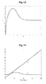
- FIG. 14 depicts a trajectory of a front wheel steer robot (FSR) with the addition of saturation and noise.
- FSR front wheel steer robot
- FIG. 15 depicts x and y components of the trajectory of FIG. 14 .
- FIG. 16 depicts control signals corresponding to the trajectory of FIG. 14 .
- FIG. 17 depicts x and y components of the trajectory of FIG. 11 with the addition of parameter errors.
- FIG. 18 depicts control signals corresponding to the trajectory of FIG. 17 .
- FIG. 19 depicts an environment described by an uncertainty map.
- FIG. 20 depicts a guidance field corresponding to FIG. 19 .
- FIG. 21 depicts a front wheel steer robot (FSR) navigating in the environment described by the uncertainty map of FIG. 19 .
- FSR front wheel steer robot
- DDR differential drive robot
- FIG. 23 depicts x and y components of the trajectory of FIG. 22 .
- FIG. 24 depicts tangential and angular velocities associated with FIG. 22 .
- FIG. 25 depicts control torques associated with the trajectory of FIG. 22 .
- FIG. 26 depicts the trajectory of FIG. 22 with the addition of actuator noise.
- FIG. 27 depicts the control torques corresponding to the trajectory of FIG. 26 .
- FIG. 28 depicts the trajectory of FIG. 22 with the addition of 85% actuator saturation.
- FIG. 29 depicts the control torques corresponding to the trajectory of FIG. 28 .
- FIG. 30 depicts the trajectory of FIG. 22 with the addition of 95% actuator saturation.
- FIG. 31 depicts the control torques corresponding to the trajectory of FIG. 30 .
- FIG. 32 depicts a velocity reference field.
- FIG. 33 depicts a trajectory of a differential drive robot (DDR) corresponding to FIG. 32 .
- DDR differential drive robot
- FIG. 34 depicts control torques corresponding to the trajectory of FIG. 33 .
- FIG. 35 depicts different trajectories of a differential drive robot (DDR) in response to the velocity reference field of FIG. 32 and actuator saturation.
- DDR differential drive robot
- FIG. 36 depicts one embodiment of a robot controller for the mobile robot.
- a method of controlling a position of a robot includes controlling the robot using a velocity synchronizing signal.
- the velocity synchronizing signal may be applied to differential drive robots (DDR) or to front wheel steered robots (FSR).
- the method of controlling may comprise: transferring a plan to a controller including a processor and memory, storing the plan in the memory, the plan including a reference velocity field vector; transferring parameters of the robot to the memory of the controller, the parameters including kinematics of motion of the robot; calculating, in the processor of the controller, a synchronization signal, S, based on the parameters of the robot; calculating, in the processor of the controller, a control signal, U, based on the synchronization signal S; and generating, in the processor of the controller, the control signal, U, to synchronize an actual velocity of the robot to navigate the robot according to the plan.
- the plan 1 may be in the form of a reference field, ⁇ dot over (X) ⁇ d(X).
- the plan 1 enables the controller to perform spatial planning action of moving the robot while avoiding obstacles.
- FIG. 1 depicts exemplary starting points 2 A, 2 B, 2 C, 2 D, an exemplary finish point 3 , and respective trajectories A, B, C, D between the exemplary starting points 2 A, 2 B, 2 C, 2 D and the finish point 3 .
- the controller may perform a synchronizing control action 10 , as shown in FIG. 2 , whereby the desired velocity field from the plan 1 is synchronized with a current velocity of the robot in order to achieve joint planning and control of the mobile robot.
- a velocity field vector of the plan may be used to guide and instruct the robot as to which direction it should move such that the robot reaches the target in a desired manner.
- the velocity field can guide the robot everywhere in a region the robot is supposed to operate, G(x), where x is a point in the region.
- the parameters of the robot may be transferred to the controller of the robot.
- the transfer of the parameters may be performed via a wired or wireless connection.
- the transfer of the parameters may occur prior to, during, or after the controller is installed on the robot.
- the parameters of the robot may include a radius of the robot's wheels, a width of the robot, a tangential velocity of the robot, an angular speed of the robot, and angular speeds of the robot's respective left and right wheels.
- an exemplary differential drive robot may include parameters such as a left wheel 31 , a right wheel 32 , a radius 33 of at least one of the left wheel 31 and the right wheel 32 , a width of the robot 34 , and angular speeds of the robot's respective left 35 and right wheels 36 .
- the kinematics of motion of the differential drive robot (DDR) may be described as:
- the processor of the controller may calculate a synchronization signal, S, for the differential drive robot (DDR) based on the parameters of the robot.
- the calculating may include determining the synchronization signal, S, by:
- the processor of the controller may calculate a control signal, U, for the differential drive robot (DDR) and the calculating may include determining the control signal, U, by:
- the processor of the controller may generate the calculated control signal, U, to synchronize an actual velocity of the differential drive robot (DDR) to navigate the robot according to the plan.
- DDR differential drive robot
- the parameters of the robot may be transferred to the controller of the robot.
- the transfer of the parameters may be performed via a wired or wireless connection.
- the transfer of the parameters may occur prior to, during, or after the controller is installed on the robot.
- the parameters of the robot may include a normal distance between a center of a front wheel and an axis of a rear set of wheels, an angular speed of the rear set of wheels, and a steering angle of the front wheel.
- an exemplary front wheel steer robots may include parameters such as a normal distance 301 between the center of a front wheel 302 and an axis of the rear wheels 303 , an angular speed 305 of the rear wheels 304 , and a steering angle 305 of the front wheel 302 .
- the kinematics of motion of the front wheel steer robots (FSR) may be described as:
- the processor of the controller may calculate a synchronization signal, S, for the front wheel steer robots (FSR) based on the parameters of the robot.
- the calculating may include determining the synchronization signal, S, by:
- the processor of the controller may calculate a control signal, U, for the front wheel steer robots (FSR) and the calculating may include determining the control signal, U, by:
- the processor of the controller may generate the calculated control signal, U, to synchronize an actual velocity of the front wheel steer robots (FSR) to navigate the robot according to the plan.
- FSR front wheel steer robots
- a method of controlling a position of a robot includes controlling the robot using a torque synchronizing signal.
- the torque synchronizing signal may be applied to differential drive robots (DDR).
- the method of controlling may comprise: transferring a plan to a controller including a processor and memory, storing the plan in the memory, the plan including a reference velocity field vector; transferring parameters of the robot to the memory of the controller, the parameters including kinematics of motion of the robot; calculating, in the processor of the controller, a synchronization signal, S, based on the parameters of the robot; calculating, in the processor of the controller, a control signal, U, based on the synchronization signal S; and generating, in the processor of the controller, the control signal, U, to synchronize an actual torque of the robot to navigate the robot according to the plan.
- DDR differential drive robots
- the parameters of the robot may be transferred to the controller of the robot.
- the transfer of the parameters may be performed via a wired or wireless connection.
- the transfer of the parameters may occur prior to, during, or after the controller is installed on the robot.
- the parameters of the robot may include a mass of the robot and torque of the robot's respective left and right wheels.
- An exemplary differential drive robot may include parameters such a mass of the robot, M, a first torque, T L , applied to a left wheel of at least two wheels, and a second torque, T R , applied to a right wheel of the at least two wheels.
- a first actuation stage of motion of the differential drive robot (DDR) may be described as:
- [ x ⁇ y ⁇ ⁇ ⁇ ] [ cos ⁇ ( ⁇ ) 0 sin ⁇ ⁇ ( ⁇ ) 0 0 1 ] ⁇ [ ⁇ . ⁇ . ] + [ - sin ⁇ ⁇ ( ⁇ ) ⁇ ⁇ . 0 cos ⁇ ( ⁇ ) ⁇ ⁇ . 0 0 ] ⁇ [ ⁇ ⁇ ] .
- a second actuation stage of motion of the differential drive robot may be described as:
- the processor of the controller may calculate a synchronization signal, S, for the differential drive robot (DDR) based on the parameters of the robot.
- the calculating may include determining the synchronization signal, S, by:
- a damping force S D may be added to the synchronizing force to ensure stability in the local coordinates of the robot.
- the calculating may include determining the damping force S D , by:
- the processor of the controller may calculate a control signal, U, for the differential drive robot (DDR) and the calculating may include determining the control signal, U, by:
- the processor of the controller may generate the calculated control signal, U, to synchronize an actual first torque, T L , applied to a left wheel of at least two wheels, and an actual second torque, T R , applied to a right wheel of the at least two wheels of the differential drive robot (DDR) to navigate the robot according to the plan.
- U the calculated control signal
- exemplary simulations are detailed to verify the capabilities of the controller in joint planning and control of the mobile robot.
- the examples demonstrate the controller's ability to efficiently perform point-to-point movements.
- the examples also demonstrate the ease in which the controller's parameters can be tuned.
- a front wheel steer robot (FSR) is required to move in free space from an initial position (0, ⁇ 1) to a final position (1,0).
- the initial orientation of the robot is ⁇ /2.
- a velocity reference field is shown in FIG. 6 and the velocity of the robot is controlled.
- FIG. 7 shows the robot's trajectory and FIG. 8 shows the corresponding x and y components as a function of time.
- the robot converged to the target in a steady over-damped manner.
- the well-behaved control signals are shown in FIG. 9 .
- a second exemplary simulation the ability of the controller to make a front wheel steer robot (FSR) track a behavior that is encoded in a reference velocity field is demonstrated.
- FSR front wheel steer robot
- a free space environment is used.
- the initial conditions and the controller parameters are kept the same as in the first exemplary simulation.
- a gradient guidance field is shown in FIG. 10 .
- the guidance field encodes the behavior: the robot moves along the x-axis at a constant speed and maintains the centerline.
- the generated trajectory is shown in FIG. 11 and its x and y components are shown in FIG. 12 .
- the trajectory converges in a well-behaved manner to the desired trajectory with constant x-velocity and zero y-velocity.
- the corresponding control signals, shown in FIG. 13 are also well-behaved.
- the robustness of the velocity controller is tested for both actuator noise and saturation.
- the environment, navigation field and controller used in this example are the same as the ones used in the previous example.
- a uniformly-distributed noise ( ⁇ 0.2, 0.2) is added to the control signal corresponding to the trajectory shown in FIG. 11 .
- the control signal is then subjected to a saturation nonlinearity that limits the value of the control signal to the period ( ⁇ 0.5, 0.5) before applying it to the robot.
- the resulting trajectory is shown in FIG. 14 and the corresponding x and y components are shown in FIG. 15 .
- the control signals are shown in FIG. 16 .
- the robot is still able to execute the behavior in the guidance field and move at a constant velocity along the centerline.
- the transient response was marginally affected and the path remains smooth.
- the robustness of the controller to uncertainty in the parameters is also tested.
- the resulting trajectory is shown in FIG. 17 and the control signals are shown in FIG. 18 .
- the robot is still able to actualize the guidance signal.
- the impact of the parameter error on the transients is quite marginal and the control signals are still well-behaved.
- a front wheel steer robot FSR
- the environment is described by a scalar field (uncertainty map) representing the fitness of each point of space to support motion, as shown in FIG. 19 .
- the same controller used in previous example is used with this example.
- the reference velocity field shown in FIG. 20 , is generated using the harmonic approach.
- the resulting trajectories from the reference velocity field and the robot are shown in FIG. 21 . Both trajectories are superimposed on an intensity map that represents the fitness field describing the environment. The higher the brightness of the intensity map the better support the point in space has for motion.
- the dotted blue trajectory is laid by the harmonic planner and the solid red trajectory is laid by the robot.
- a fourth exemplary simulation the control structure of the torque controlled differential drive robot (DDR) is tested.
- the reference velocity field in FIG. 10 is used.
- the trajectory is shown in FIG. 22 and corresponding x and y components are shown in FIG. 23 .
- the orientation and the tangential speed are shown in FIG. 24 and the well-behaved torques that are controlling the wheels of the robot are shown in FIG. 25 .
- the robustness of the torque controlled differential drive robot (DDR) controller is tested.
- the same settings in the previous exemplary simulation are used.
- the robustness of the controller is tested in the presence of actuator noise by adding uniform noise in the period ⁇ -0.5, 0.5 ⁇ to the control signal.
- the resulting trajectory is shown in FIG. 26 and the control signals are shown in FIG. 27 .
- the impact of noise on the response is minimal.
- the test is repeated to assess the ability of the controller to tolerate actuator saturation.
- the control signal is restricted to the period ⁇ -0.5, 0.5 ⁇ . When compared to saturation-free maximum value of 2.8, this amounts to about 85% of the signal magnitude.
- the trajectory is shown in FIG. 28 and the control signals are in FIG. 29 . As can be seen, other than slowing the response a little, the impact of this severe saturation nonlinearity is almost negligible. Comparable behavior was observed for high level of saturation. Abrupt change in the quality of the response is noticed at a 95% saturation ⁇ 0.15, 0.15 ⁇ . The trajectory for the 95% saturation nonlinearity is shown in FIG. 30 and the corresponding control signal is shown in FIG. 31 .
- FIG. 32 shows the point-to-point motion capabilities of the torque controller for an involved harmonic velocity reference guidance field.
- the HPF gradient guidance field superimposed on the environment is shown in FIG. 32 .
- the kinematic trajectory is also shown in FIG. 32 .
- FIG. 33 shows the dynamic trajectory of the differential drive robot (DDR).
- the control signals are shown in FIG. 34 . As can be seen the control signals are well-behaved.
- T m C ⁇ max ⁇ ( max r ⁇ ( ⁇ T R ⁇ ( t ) ⁇ ) , max t ⁇ ( ⁇ T L ⁇ ( t ) ⁇ ) )
- T R and T L are the torques for then non-saturated case, C is a constant representing the percentage of saturation.
- the maximum torque for the non-saturated actuators is equal to 0.103 Nm.
- the controller showed remarkable robustness to saturation.
- FIG. 36 illustrates a robot controller 101 upon which an embodiment of the present invention may be implemented.
- the robot controller 101 includes a bus 102 or other communication mechanism for communicating information, and a processor 103 coupled with the bus 102 for processing the information.
- the robot controller 101 also includes a main memory 104 , such as a random access memory (RAM) or other dynamic storage device (e.g., dynamic RAM (DRAM), static RAM (SRAM), and synchronous DRAM (SDRAM)), coupled to the bus 102 for storing information and instructions to be executed by processor 103 .
- RAM random access memory
- DRAM dynamic RAM
- SRAM static RAM
- SDRAM synchronous DRAM
- the plan, parameters of a robot, and instructions for the robot may be stored in main memory 104 .
- the robot controller 101 further includes a read only memory (ROM) 105 or other static storage device (e.g., programmable ROM (PROM), erasable PROM (EPROM), and electrically erasable PROM (EEPROM)) coupled to the bus 102 for storing static information and instructions for the processor 103 .
- ROM read only memory
- PROM programmable ROM
- EPROM erasable PROM
- EEPROM electrically erasable PROM
- the robot controller 101 may also include a disk controller 106 coupled to the bus 102 to control one or more storage devices for storing information and instructions, such as a magnetic hard disk 107 , and a removable media drive 108 (e.g., floppy disk drive, read-only compact disc drive, read/write compact disc drive, compact disc jukebox, tape drive, and removable magneto-optical drive).
- the storage devices may be added to the robot controller 101 using an appropriate device interface (e.g., small computer system interface (SCSI), integrated device electronics (IDE), enhanced-IDE (E-IDE), direct memory access (DMA), or ultra-DMA).
- SCSI small computer system interface
- IDE integrated device electronics
- E-IDE enhanced-IDE
- DMA direct memory access
- ultra-DMA ultra-DMA
- the robot controller 101 may also include special purpose logic devices (e.g., application specific integrated circuits (ASICs)) or configurable logic devices (e.g., simple programmable logic devices (SPLDs), complex programmable logic devices (CPLDs), and field programmable gate arrays (FPGAs)).
- ASICs application specific integrated circuits
- SPLDs simple programmable logic devices
- CPLDs complex programmable logic devices
- FPGAs field programmable gate arrays
- the robot controller 101 may also include a display controller 109 coupled to the bus 102 to control a display 110 , such as a cathode ray tube (CRT) or a liquid crystal display (LCD), for displaying information to a robot operator.
- the computer system includes input devices, such as a keyboard 111 and a pointing device 11 , for interacting with a robot operator and providing information to the processor 103 .
- the pointing device 11 may be a mouse, a trackball, or a pointing stick for communicating direction information, and command selections to the processor 103 and for controlling cursor movement on the display 110 .
- a touch screen (not illustrated) may be provided to receive inputs, direction information, and command selections.
- a printer may provide printed listings of data stored and/or generated by the controller 101 .
- the robot controller 101 performs a portion or all of the processing steps of the invention in response to the processor 103 executing one or more sequences of one or more instructions contained in a memory, such as the main memory 104 .
- a memory such as the main memory 104 .
- Such instructions may be read into the main memory 104 from another computer readable medium, such as a hard disk 107 or a removable media drive 108 .
- processors in a multi-processing arrangement may also be employed to execute the sequences of instructions contained in main memory 104 .
- hard-wired circuitry may be used in place of or in combination with software instructions. Thus, embodiments are not limited to any specific combination of hardware circuitry and software.
- the robot controller 101 includes at least one computer readable medium or memory for holding instructions programmed according to the teachings of the invention and for containing data structures, tables, records, or other data described herein.
- Examples of computer readable media are compact discs, hard disks, floppy disks, tape, magneto-optical disks, PROMs (EPROM, EEPROM, flash EPROM), DRAM, SRAM, SDRAM, or any other magnetic medium, compact discs (e.g., CD-ROM), or any other optical medium, punch cards, paper tape, or other physical medium with patterns of holes, a carrier wave (described below), or any other medium from which a computer can read.
- the present invention includes software for controlling the robot controller 101 , for driving a device or devices for implementing the invention, and for enabling the robot controller 101 to interact with a human user (e.g., receive plan inputs from user or provide operating parameter and outputs to user).
- software may include, but is not limited to, device drivers, operating systems, development tools, and applications software.
- Such computer readable media further includes the computer program product of the present invention for performing all or a portion (if processing is distributed) of the processing performed in implementing the invention.
- the computer code devices of the present invention may be any interpretable or executable code mechanism, including but not limited to scripts, interpretable programs, dynamic link libraries (DLLs), Java classes, and complete executable programs. Moreover, parts of the processing of the present invention may be distributed for better performance, reliability, and/or cost.
- Non-volatile media includes, for example, optical, magnetic disks, and magneto-optical disks, such as the hard disk 107 or the removable media drive 108 .
- Volatile media includes dynamic memory, such as the main memory 104 .
- Transmission media includes coaxial cables, copper wire and fiber optics, including the wires that make up the bus 102 . Transmission media also may also take the form of acoustic or light waves, such as those generated during radio wave and infrared data communications.
- Various forms of computer readable media may be involved in carrying out one or more sequences of one or more instructions to processor 103 for execution.
- the instructions may initially be carried on a magnetic disk of a remote computer.
- the remote computer can load the instructions for implementing all or a portion of the present invention remotely into a dynamic memory and send the instructions over a telephone line using a modem.
- a modem local to the robot controller 101 may receive the data on the telephone line and use an infrared transmitter to convert the data to an infrared signal.
- An infrared detector coupled to the bus 102 can receive the data carried in the infrared signal and place the data on the bus 102 .
- the bus 102 carries the data to the main memory 104 , from which the processor 103 retrieves and executes the instructions.
- the instructions received by the main memory 104 may optionally be stored on storage device 107 or 108 either before or after execution by processor 103 .
- the robot controller 101 also includes a communication interface 113 coupled to the bus 102 .
- the communication interface 113 provides a two-way data communication coupling to a network link 114 that is connected to, for example, a local area network (LAN) 115 , or to another communications network 116 such as the Internet.
- the communication interface 113 may be a network interface card to attach to any packet switched LAN.
- the communication interface 113 may be an asymmetrical digital subscriber line (ADSL) card, an integrated services digital network (ISDN) card or a modem to provide a data communication connection to a corresponding type of communications line.
- Wireless links may also be implemented.
- the communication interface 113 sends and receives electrical, electromagnetic or optical signals that carry digital data streams representing various types of information.
- the network link 114 typically provides data communication through one or more networks to other data devices.
- the network link 114 may provide a connection to another computer through a local network 115 (e.g., a LAN) or through equipment operated by a service provider, which provides communication services through a communications network 116 .
- the local network 114 and the communications network 116 use, for example, electrical, electromagnetic, or optical signals that carry digital data streams, and the associated physical layer (e.g., CAT 5 cable, coaxial cable, optical fiber, etc).
- the signals through the various networks and the signals on the network link 114 and through the communication interface 113 , which carry the digital data to and from the robot controller 101 may be implemented in baseband signals, or carrier wave based signals.
- the baseband signals convey the digital data as unmodulated electrical pulses that are descriptive of a stream of digital data bits, where the term “bits” is to be construed broadly to mean symbol, where each symbol conveys at least one or more information bits.
- the digital data may also be used to modulate a carrier wave, such as with amplitude, phase and/or frequency shift keyed signals that are propagated over a conductive media, or transmitted as electromagnetic waves through a propagation medium.
- the digital data may be sent as unmodulated baseband data through a “wired” communication channel and/or sent within a predetermined frequency band, different than baseband, by modulating a carrier wave.
- the robot controller 101 can transmit and receive data, including program code, through the network(s) 115 and 116 , the network link 114 and the communication interface 113 .
- the network link 114 may provide a connection through a LAN 115 to a mobile device 117 such as a personal digital assistant (PDA) laptop computer, or cellular telephone.
- PDA personal digital assistant
- the robot controller 101 may receive instructions or commands stored on the hard disk 117 and/or stored on the removable media drive 108 . In one embodiment, the robot controller 101 may receive instructions or commands stored on a remote location that is transferred to the robot controller 101 via the network 114 . The instructions or commands may include a plan that contains a reference velocity field vector of a robot. The robot controller 101 may receive information or signals from at least one input sensor of the robot via the communication interface 113 .
- the input sensor may provide the robot controller 101 with one or more of the following signals: angular speed of a left wheel of the robot ( ⁇ L ), angular speed of a right wheel of a robot ( ⁇ R ), tangential velocity of the robot ( ⁇ ), angular speed of the robot ( ⁇ ), angular speed of rear wheels of a robot ( ⁇ h ), and/or steering angle of the front wheel ( ⁇ ).
- the processor 103 may process the information or signals, perform calculations to determine a synchronization signal, and perform calculations to determine a control signal. Additionally, the processor 103 may generate a control signal to synchronize an actual velocity and/or an actual torque of the robot to navigate the robot according to the plan. The generated control signal may be transmitted to another component of the robot, such as a motor, to execute the synchronization of the actual velocity and/or actual torque.
Abstract
Description
where P=[x y θ]t, λ=[νω]t, U=[ωR ωL]t, r is the radius of the robot's wheels, W is the width of the robot, ωR and ωL are the angular speeds of the right and left wheels of the robot, respectively, ν is the tangential velocity of the robot, and ω is the angular speed of the robot.
where K1, K2 are positive constants and θ is the angle of the robot.
Additionally, the control signal, U, may be referred to as:
U=Q −1(S).
where L is the normal distance between the center of the front wheel and the line connecting the rear wheels, ωh is the angular speed of the rear wheels, and φ is the steering angle of the front wheel (π/2>φ>−π/2).
where K1, K2 are positive constants and θ is the angle of the robot. The processor of the controller may calculate a control signal, U, for the front wheel steer robots (FSR) and the calculating may include determining the control signal, U, by:
Additionally, the control signal, U, may be referred to as:
U=Q −1(S).
where ν is the tangential speed of the robot, K1 and K2 are positive constants. A damping force SD may be added to the synchronizing force to ensure stability in the local coordinates of the robot. The calculating may include determining the damping force SD, by:
Claims (17)
Priority Applications (1)
| Application Number | Priority Date | Filing Date | Title |
|---|---|---|---|
| US14/106,040 US9098079B2 (en) | 2013-12-13 | 2013-12-13 | Method of joint planning and control of a rigid, separable non-holonomic mobile robot using a harmonic potential field approach |
Applications Claiming Priority (1)
| Application Number | Priority Date | Filing Date | Title |
|---|---|---|---|
| US14/106,040 US9098079B2 (en) | 2013-12-13 | 2013-12-13 | Method of joint planning and control of a rigid, separable non-holonomic mobile robot using a harmonic potential field approach |
Publications (2)
| Publication Number | Publication Date |
|---|---|
| US20150168939A1 US20150168939A1 (en) | 2015-06-18 |
| US9098079B2 true US9098079B2 (en) | 2015-08-04 |
Family
ID=53368327
Family Applications (1)
| Application Number | Title | Priority Date | Filing Date |
|---|---|---|---|
| US14/106,040 Expired - Fee Related US9098079B2 (en) | 2013-12-13 | 2013-12-13 | Method of joint planning and control of a rigid, separable non-holonomic mobile robot using a harmonic potential field approach |
Country Status (1)
| Country | Link |
|---|---|
| US (1) | US9098079B2 (en) |
Cited By (1)
| Publication number | Priority date | Publication date | Assignee | Title |
|---|---|---|---|---|
| US11958183B2 (en) | 2020-09-18 | 2024-04-16 | The Research Foundation For The State University Of New York | Negotiation-based human-robot collaboration via augmented reality |
Families Citing this family (1)
| Publication number | Priority date | Publication date | Assignee | Title |
|---|---|---|---|---|
| JP2023542515A (en) * | 2020-09-23 | 2023-10-10 | デクステリティ・インコーポレーテッド | Speed control based robot system |
Citations (14)
| Publication number | Priority date | Publication date | Assignee | Title |
|---|---|---|---|---|
| US4885515A (en) | 1986-12-12 | 1989-12-05 | Fanuc Ltd. | Velocity control apparatus |
| US5758298A (en) | 1994-03-16 | 1998-05-26 | Deutsche Forschungsanstalt Fur Luft-Und Raumfahrt E.V. | Autonomous navigation system for a mobile robot or manipulator |
| US6046566A (en) | 1998-04-21 | 2000-04-04 | Fanuc Ltd. | Method of and apparatus for controlling a plurality of servomotors |
| JP2000308399A (en) | 1999-04-14 | 2000-11-02 | Meidensha Corp | Velocity control device of rotating machine |
| US6608459B2 (en) | 2000-12-11 | 2003-08-19 | Daihen Corp. | Method and device for servo-controlling DC motor |
| US6885160B2 (en) | 2001-04-20 | 2005-04-26 | Seiko Epson Corporation | Drive control |
| JP2006227717A (en) | 2005-02-15 | 2006-08-31 | Yaskawa Electric Corp | Motion control system, and control method for the same |
| US7520184B2 (en) | 2004-02-20 | 2009-04-21 | Panasonic Corporation | Angular velocity sensor |
| US20100057252A1 (en) | 2008-09-04 | 2010-03-04 | Samsung Electronics Co., Ltd. | Robot and method of controlling the same |
| US7872436B2 (en) | 2003-05-22 | 2011-01-18 | Abb Ab | Control method for a robot |
| US8256542B2 (en) | 2006-10-06 | 2012-09-04 | Irobot Corporation | Robotic vehicle |
| US20130105233A1 (en) | 2006-10-06 | 2013-05-02 | Irobot Corporation | Robotic vehicle |
| US8442721B2 (en) | 2009-09-30 | 2013-05-14 | Iucf-Hyu (Industry-University Cooperation Foundation Hanyang University) | Steering controller for movable robot, steering control method using the steering controller and movable robot system using the steering controller |
| US20130289870A1 (en) * | 2012-04-26 | 2013-10-31 | The Government Of The United States Of America, As Represented By The Secretary Of The Navy | Collaborative Robot Manifold Tracker |
-
2013
- 2013-12-13 US US14/106,040 patent/US9098079B2/en not_active Expired - Fee Related
Patent Citations (14)
| Publication number | Priority date | Publication date | Assignee | Title |
|---|---|---|---|---|
| US4885515A (en) | 1986-12-12 | 1989-12-05 | Fanuc Ltd. | Velocity control apparatus |
| US5758298A (en) | 1994-03-16 | 1998-05-26 | Deutsche Forschungsanstalt Fur Luft-Und Raumfahrt E.V. | Autonomous navigation system for a mobile robot or manipulator |
| US6046566A (en) | 1998-04-21 | 2000-04-04 | Fanuc Ltd. | Method of and apparatus for controlling a plurality of servomotors |
| JP2000308399A (en) | 1999-04-14 | 2000-11-02 | Meidensha Corp | Velocity control device of rotating machine |
| US6608459B2 (en) | 2000-12-11 | 2003-08-19 | Daihen Corp. | Method and device for servo-controlling DC motor |
| US6885160B2 (en) | 2001-04-20 | 2005-04-26 | Seiko Epson Corporation | Drive control |
| US7872436B2 (en) | 2003-05-22 | 2011-01-18 | Abb Ab | Control method for a robot |
| US7520184B2 (en) | 2004-02-20 | 2009-04-21 | Panasonic Corporation | Angular velocity sensor |
| JP2006227717A (en) | 2005-02-15 | 2006-08-31 | Yaskawa Electric Corp | Motion control system, and control method for the same |
| US8256542B2 (en) | 2006-10-06 | 2012-09-04 | Irobot Corporation | Robotic vehicle |
| US20130105233A1 (en) | 2006-10-06 | 2013-05-02 | Irobot Corporation | Robotic vehicle |
| US20100057252A1 (en) | 2008-09-04 | 2010-03-04 | Samsung Electronics Co., Ltd. | Robot and method of controlling the same |
| US8442721B2 (en) | 2009-09-30 | 2013-05-14 | Iucf-Hyu (Industry-University Cooperation Foundation Hanyang University) | Steering controller for movable robot, steering control method using the steering controller and movable robot system using the steering controller |
| US20130289870A1 (en) * | 2012-04-26 | 2013-10-31 | The Government Of The United States Of America, As Represented By The Secretary Of The Navy | Collaborative Robot Manifold Tracker |
Cited By (1)
| Publication number | Priority date | Publication date | Assignee | Title |
|---|---|---|---|---|
| US11958183B2 (en) | 2020-09-18 | 2024-04-16 | The Research Foundation For The State University Of New York | Negotiation-based human-robot collaboration via augmented reality |
Also Published As
| Publication number | Publication date |
|---|---|
| US20150168939A1 (en) | 2015-06-18 |
Similar Documents
| Publication | Publication Date | Title |
|---|---|---|
| Feron et al. | A randomized attitude slew planning algorithm for autonomous spacecraft | |
| James et al. | Reactionless maneuvering of a space robot in precapture phase | |
| Roozegar et al. | Optimal motion planning and control of a nonholonomic spherical robot using dynamic programming approach: simulation and experimental results | |
| CN103692440A (en) | Spatial path tracking method of continuous robot | |
| CN110362070A (en) | Path follower method, system, electronic equipment and storage medium | |
| Sun et al. | Trajectory-tracking control of Mecanum-wheeled omnidirectional mobile robots using adaptive integral terminal sliding mode | |
| Zhang et al. | An iterative linear quadratic regulator based trajectory tracking controller for wheeled mobile robot | |
| Low | A flexible virtual structure formation keeping control design for nonholonomic mobile robots with low-level control systems, with experiments | |
| US9098079B2 (en) | Method of joint planning and control of a rigid, separable non-holonomic mobile robot using a harmonic potential field approach | |
| Pinto et al. | Modified approach using variable charges to solve inherent limitations of potential fields method | |
| Macenski et al. | Regulated pure pursuit for robot path tracking | |
| CN104460678B (en) | Spacecraft posture control method based on Sigmoid nonlinear sliding mode function | |
| Kim et al. | Shared teleoperation of a vehicle with a virtual driving interface | |
| Zhang et al. | Autonomous underwater vehicle depth control based on an improved active disturbance rejection controller | |
| Delrobaei et al. | Parking control of a center-articulated mobile robot in presence of measurement noise | |
| Cuesta et al. | Fuzzy control of reactive navigation with stability analysis based on conicity and Lyapunov theory | |
| Hassani et al. | Control points searching algorithm for autonomous mobile robot navigation with obstacle avoidance | |
| Macek et al. | Path following for autonomous vehicle navigation with inherent safety and dynamics margin | |
| Huang et al. | Headland turning control method simulation of autonomous agricultural machine based on improved pure pursuit model | |
| Lee et al. | Trajectory planning with shadow trolleys for an autonomous vehicle on bending roads and switchbacks | |
| Korayem et al. | Dynamic optimal payload path planning of mobile manipulators among moving obstacles | |
| Lu et al. | Tracking control of wheeled mobile robots using iterative learning controller | |
| KR101957742B1 (en) | Real-time obstacle avoidance method of non-holonomic mobile robot using expanded guide circle, and system for controlling non-holonomic mobile robot remotely implementing the same | |
| Varcholik et al. | Interactions and training with unmanned systems and the nintendo wiimote | |
| Mascaró et al. | Topological Navigation in Tunnels: LHD Navigation as a Case Study |
Legal Events
| Date | Code | Title | Description |
|---|---|---|---|
| AS | Assignment |
Owner name: KING FAHD UNIVERSITY OF PETROLEUM AND MINERALS, SA Free format text: ASSIGNMENT OF ASSIGNORS INTEREST;ASSIGNOR:MASOUD, AHMAD A;REEL/FRAME:031784/0503 Effective date: 20131127 |
|
| STCF | Information on status: patent grant |
Free format text: PATENTED CASE |
|
| MAFP | Maintenance fee payment |
Free format text: PAYMENT OF MAINTENANCE FEE, 4TH YR, SMALL ENTITY (ORIGINAL EVENT CODE: M2551); ENTITY STATUS OF PATENT OWNER: SMALL ENTITY Year of fee payment: 4 |
|
| FEPP | Fee payment procedure |
Free format text: MAINTENANCE FEE REMINDER MAILED (ORIGINAL EVENT CODE: REM.); ENTITY STATUS OF PATENT OWNER: SMALL ENTITY |
|
| LAPS | Lapse for failure to pay maintenance fees |
Free format text: PATENT EXPIRED FOR FAILURE TO PAY MAINTENANCE FEES (ORIGINAL EVENT CODE: EXP.); ENTITY STATUS OF PATENT OWNER: SMALL ENTITY |
|
| STCH | Information on status: patent discontinuation |
Free format text: PATENT EXPIRED DUE TO NONPAYMENT OF MAINTENANCE FEES UNDER 37 CFR 1.362 |
|
| FP | Lapsed due to failure to pay maintenance fee |
Effective date: 20230804 |