JP4174635B2 - Inkjet recording device - Google Patents
Inkjet recording device Download PDFInfo
- Publication number
- JP4174635B2 JP4174635B2 JP20625998A JP20625998A JP4174635B2 JP 4174635 B2 JP4174635 B2 JP 4174635B2 JP 20625998 A JP20625998 A JP 20625998A JP 20625998 A JP20625998 A JP 20625998A JP 4174635 B2 JP4174635 B2 JP 4174635B2
- Authority
- JP
- Japan
- Prior art keywords
- recording head
- carriage
- recording
- pressed
- storage cap
- Prior art date
- Legal status (The legal status is an assumption and is not a legal conclusion. Google has not performed a legal analysis and makes no representation as to the accuracy of the status listed.)
- Expired - Fee Related
Links
- 238000003860 storage Methods 0.000 claims description 51
- 230000001105 regulatory effect Effects 0.000 claims description 8
- 238000001035 drying Methods 0.000 claims description 6
- 239000000976 ink Substances 0.000 description 34
- 238000012423 maintenance Methods 0.000 description 7
- 238000010926 purge Methods 0.000 description 7
- 238000003825 pressing Methods 0.000 description 5
- 238000000926 separation method Methods 0.000 description 5
- 229920003002 synthetic resin Polymers 0.000 description 5
- 239000000057 synthetic resin Substances 0.000 description 5
- 230000005540 biological transmission Effects 0.000 description 4
- 230000002950 deficient Effects 0.000 description 4
- 230000000694 effects Effects 0.000 description 4
- 239000002184 metal Substances 0.000 description 3
- 238000013459 approach Methods 0.000 description 2
- 230000003028 elevating effect Effects 0.000 description 2
- 230000001360 synchronised effect Effects 0.000 description 2
- 238000011144 upstream manufacturing Methods 0.000 description 2
- 239000003086 colorant Substances 0.000 description 1
- 238000010586 diagram Methods 0.000 description 1
- 239000013013 elastic material Substances 0.000 description 1
- 239000004973 liquid crystal related substance Substances 0.000 description 1
- 238000004519 manufacturing process Methods 0.000 description 1
- 239000000463 material Substances 0.000 description 1
- 230000002093 peripheral effect Effects 0.000 description 1
Images


Landscapes
- Ink Jet (AREA)
Description
【0001】
【発明の属する技術分野】
本発明は、ファクシミリ装置や複写機等における被記録媒体に画像形成するための記録装置に係り、より詳しくは、待機させているとき、インクジェット式の記録ヘッドのノズル部が乾燥するのを防止する保存手段の構造に関するものである。
【0002】
【従来の技術】
従来から、ファクシミリ装置や複写機等の画像形成装置において、被記録媒体としての用紙に画像を形成するための記録部として、インクを噴射する記録ヘッドを備えたものが周知である。
この種の記録ヘッドのノズル部が乾燥することによりインクの吐出不良が発生するの防止し、また記録ヘッドの状態を良好に保全するため、例えば、特開平9−141885号公報に開示されているように、被記録媒体の搬送方向と直交する方向に前記記録ヘッドを搭載したキャリッジを往復移動可能に構成する一方、前記被記録媒体への記録領域から外れた待機位置には、保存キャップを搭載した移動部材は、前記キャリッジの移動方向とほぼ平行状に移動可能で、且つ保存キャップが記録ヘッドのノズル部に対して接離するように回動可能に支持されており、さらに、前記移動部材は前記記録領域に近づく方向にバネ付勢されている。そして、前記待機位置に向かってキャリッジを移動させる動きに連れて、前記移動部材を前記バネの付勢力に抗して押し、このとき、移動部材は方向変換手段としてのカム部材により回動させられ、当該記録ヘッドのノズル部に向かって保存キャップが接近し、所定の待機位置で記録ヘッドが停止した時点で、前記ノズル部に保存キャップが完全に覆われるように同期させる構成が公知であった。
【0003】
【発明が解決しようとする課題】
しかしながら、前記構成では、待機位置で停止したキャリッジに対して、前記移動部材が付勢バネにより一方向に押圧されているだけであるから、その押圧方向と反対の方向に移動部材が移動可能であるので、この種のインクジェット記録装置を運搬するとき等、装置に外力が作用した場合や、前記キャリッジから移動部材が離れる方向に装置を傾ける等した場合に、保存キャップが前記ノズル部から外れてしまい、記録ヘッドのノズル部の乾燥防止や保全の作用を果たせなくなるという問題があった。
【0004】
本発明は、前記従来の問題を解決するためになされたものであり、装置への外力に拘らず、前記記録ヘッドのノズル部に保存キャップを被せた状態を保持できるようにしたインクジェット記録装置を提供することを目的とするものである。
【0005】
【課題を解決するための手段】
この目的を達成するため、請求項1に記載した発明のインクジェット記録装置は、インクを噴射する記録ヘッドを往復移動させて被記録媒体に記録を行うインクジェット記録装置において、前記記録ヘッドのノズル部のインクの乾燥を防止するための保存キャップと、前記記録ヘッドの移動によって、前記記録ヘッドを搭載したキャリッジに設けられた突起部に押圧されて前記記録ヘッドの移動方向と同一方向に移動する被押圧部と、その被押圧部の移動に伴って前記保存キャップを前記記録ヘッドのノズル部に対してキャッピィングする方向に移動させる方向変換手段と、前記方向変換手段を介して前記保存キャップが前記記録ヘッドのノズル部にキャッピィングしたとき、前記突起部に押される前記被押圧部が、前記突起部と前記キャリッジに設けられた規制片との間に嵌まって挟持されるように構成されているものである。
【0006】
また、請求項2に記載の発明は、請求項1に記載のインクジェット記録装置において、前記被押圧部が前記突起部と前記規制片との間に嵌まり込む方向は、前記記録ヘッドのノズル部に前記保存キャップがキャッピィングする方向と交差していることを特徴とするものである。
【0007】
【0008】
【0009】
【発明の実施の形態】
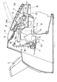
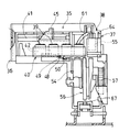
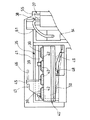
次に、本発明を具体化した実施形態を図面に基づいて説明する。図1は本発明を適用するインクジェット記録装置2を備えたファクシミリ装置1の斜視図、図2はファクシミリ装置1の概略側断面図、図3はキャリッジの移動手段及びメインテナンス部を示す概略平面図、図4はインクジェット記録装置の側面図、図5はメインテナンス部の平面図、図6は要部の拡大断面図である。
【0010】
ファクシミリ装置1の本体ケースは、図1及び図2に示すように、インクジェット記録装置2を収納し、且つ画像を形成するための用紙Pを供給するための給紙カセット3を後側の上方から装着することのできる合成樹脂製のメイン下ケース1aと、該メイン下ケース1aの上側を覆う合成樹脂製の上ケース1bとからなる。上ケース1bは、その前後方向の中途部から左右両外側に突出する筒軸部4(図2において片側のみ示す)を中心にして大きく上下回動できるように、メイン下ケース1aの側部のブラケットに枢着されている。
【0011】
そして、一方の金属製のブラケットに一端が係止され、コイル部が筒軸部4の外周に巻回され、他端が上ケース1bにおける金属製のシャーシ等の適宜箇所に係止された金属製の捩じりばね(図示せず)により、上ケース1bの上面が前方向に向かうように付勢され、通常は、図示しないフックにより、上ケース1bはその上面が上を向くように固定されている。
【0012】
さらに、上ケース1bの上面の前寄り部位には、原稿読取部としての原稿読取ユニット5が装着され、該原稿読取ユニット5の上側を、操作パネル部6にて覆う。表面に各種ファンクションキーやテンキー等の操作キー部6aと、前記操作キー部6aでの入力値や、各種の指令用の文字(キャラクタ)が表示できる液晶パネル等の表示部6bとを備えた操作パネル部6は、その後部寄り部位の左右両側の枢支軸7を中心にして前側が大きく上下回動できるように構成されている。また、上ケース1bの上面の後部寄りには、前記操作パネル部6の後端に隣接して、原稿載置部9が一体的に形成され、該原稿載置部9には、搬送される原稿の左右両側縁を案内するための左右一対の原稿ガイド体10,10が同期して左右移動可能に装着されている。
【0013】
なお、メイン下ケース1aの下面は金属板等からなる底カバー板11にて塞がれ、メイン下ケース1aの内部空間には、図示しないが、制御基板、電源基板、電話回線を介して他の電話装置やファクシミリ装置との間で会話やファクシミリデータの送受信を可能にするためのNCU(ネットワークコントロールユニット)基板等が位置されている。さらに、メイン下ケース1aの側部から外向きに突設した受け台12上に、他の電話装置との会話を行うための送受話器(ハンドセット)8が載置されている。発呼用のスピーカ(図示せず)は、メイン下ケース1a内の右側面の後部側等に固定されている。
【0014】
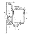
図2に示すように、原稿読取ユニット5のユニットケース5aには、原稿載置部9の近傍に配置される原稿分離送りローラ28aと、横長の密着型イメージセンサ(CIS)29と、その搬送上流側に配置される搬送ローラ対30と、搬送下流側に配置される搬送ローラ対31と、前記各ローラ28a,29,30を駆動するための駆動モータと歯車列とがフレーム内に収納された原稿搬送系駆動ユニットとが備えられている。そして、枢支軸7を中心にして前側が大きく上下回動できるように構成された操作パネル部6の下面側には、前記ユニットケース5aの上面を覆った状態のとき、前記原稿分離送りローラ28aの上面に当接する分離パッド28bと、前記密着型イメージセンサ29の上面に当接する下面が白色に塗布される等した押圧板32とが備えられており、操作パネル部6上面のキー操作等による原稿読取り指令に応じて、原稿載置部9上の原稿は、前記原稿分離送りローラ28a及び分離パッド28bを介して1枚ずつ分離して送られ、原稿が前記押圧板32とCIS29の上面との間を通過するとき、原稿の画像が読み取られるように構成されている。
【0015】
なお、前記給紙カセット3に積層された用紙Pは、メイン下ケース1aの後部内に配置された図示しないが従来から周知の構造の給紙機構としての間欠回転する回転する給紙ローラと分離パッドとによって1枚ずつ分離され、分離された用紙Pは、レジストローラ(図示せず)の箇所にて一旦用紙の先端の位置を整えて、搬送上流側ローラ33にて記録ヘッド14の下方に給送され、搬送下流側の上下対の搬送ローラ対34にて挟持搬送される途次、印字指令に応じてインク滴を用紙Pの上面に吐出して画像を記録し、その後、排紙トレイ27の箇所に排出されるように構成されている。
【0016】
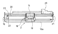
図2、図3、図4及び図5に示すように、インクジェット記録装置2におけるキャリッジ18はその下部が左右長手のシャーシフレーム16に装架された丸軸状のガイド軸17に軸支され、シャーシフレーム16の縦案内片16aに上部が摺接して左右移動可能に構成されている。そして、このキャリッジ18にカラーインクジェット式の記録ヘッド14がそのノズル部15を下向きにして装着されている。カラー記録を実行するための記録ヘッド14は、シアン、イエロー、マゼンタ、ブラックの各色のインクを吐出するための4つのノズル部を有し、この各記録ヘッド14に対して供給するインクが収納された各色毎のカートリッジ19がキャリッジ18にそれぞれ着脱可能に装着される。
【0017】
キャリッジ18の送り機構は、前記ガイド軸17と平行に延びる無端帯としてのタイミングベルト20が、シャーシフレーム16の一側寄りに配置された従動プーリ21と正逆回転可能なステッピングモータ等のキャリッジ駆動モータ22の出力軸に固定された駆動プーリ23とに巻掛けられ、タイミングベルト20の一箇所を前記キャリッジ18に連結することにより、当該キャリッジ18はガイド軸17と平行に往復移動可能となるように構成されている。
【0018】
次に、メインテナンス部29と、待機位置における保存手段35との構成の詳細について、図3、図5〜図8を参照しながら説明すると、例えば図3に示す実施例において、キャリッジ18が右方向へ移動することにより記録領域から外れるものとし、左右長手のシャーシフレーム16の右端部位に、メインテナンス部29と保存手段35とを集合させて配置するため、フレーム支持片16b,16cに対して図5の平面視図に示すような合成樹脂製の集合ケース36をビス44にて固定する。集合ケース36の左端側には、記録ヘッド14のノズル部の表面に付着したインク滴を払拭するためのノズル払拭装置(ワイパ装置)37が配置され、その右側に隣接して記録ヘッド14のインクの不吐出もしくは吐出不良を回復させるためのパージ装置(ノズル吸引装置)38が配置され、その右側〔パージ装置38からさらに記録領域の反対側の待機位置(ホームポジション)〕には、記録ヘッド14のノズル部15の数(実施例では4つ)と同じ数の保存キャップ39を備えた保存手段35が配置されている。
【0019】
即ち、前記各保存キャップ39を支持する保存キャップ移動手段としての合成樹脂製の枠状の移動部材40が、集合ケース36に一体的に形成され、キャリッジ18の移動方向と平行状に形成された丸軸41に沿って移動可能且つその軸線回りに回動可能に装着されている。前記軟質ゴム製の各保存キャップ39を支持する支持体42が移動部材40の枠内で上向き抜け不能且つ上下動可能に装着され、付勢バネ43を介して上向きに付勢されている(図6参照)。
【0020】
そして、枠状の移動部材40における回動基端部40aには、上向きに被押圧部45を一体的に突出形成する一方(図8、図11(a)〜図11(d)参照)、キャリッジ18の下面側には、図6及び図11(a)〜図11(d)に示すように、突起部46と規制片47とを横向きで、且つ段違い状にて被押圧部45に向かうように二股状に突設してあり、突起部46と規制片47との隙間間隔L1は被押圧部45の幅寸法と略等しく形成され、後述の待機位置では被押圧部45の前後縁を突起部46と規制片47とで挟持される構成となっている。
【0021】
キャリッジ18を待機位置(ホームポジション)方向(矢印A方向)移動させるとき、押圧部46にて被押圧部45を押すなど係合させて、移動部材40を丸軸41に沿って摺動移動させる。このとき、当該移動部材40における回動基端部40aの下面側に下向きに突設する摺動片48と対峙するように、集合ケース36の箇所には方向変換手段としてのカム板49を設ける。このカム板49の形状は、矢印A方向への移動部材40の移動に基づいて、前記保存キャップ39を前記キャリッジ18の移動方向と略直交する方向に移動させて、前記待機位置では、各保存キャップ39が前記各ノズル部15を下側から覆ってキャッピィングするように形成されている(図6の二点鎖線状態参照)。
【0022】
また、集合ケース36と移動部材40との間に付勢手段としての引張バネ50が装架されており、矢印A方向への移動部材40の移動量が増大するにつれて、反矢印A方向への復帰力が増大するように付勢されている。
キャリッジ18における突起部46にて被押圧部45を矢印A方向に押し始めるときには(図8の状態参照)、図11(a)及び図11(b)に示すごとく、規制片47は被押圧部45に干渉しない。
【0023】
図10に示すように、さらに、カム板49に沿って摺動片48上側に移動すると、移動部材40が上向き回動し、各保存キャップ39を前記キャリッジ18の移動方向と略直交する方向に移動させ、図6の二点鎖線で示すキャッピィング状態では、図11(c)及び図11(d)に示すごとく、規制手段としての規制片47と前押圧部46との間に被押圧部45が嵌まり込む。これにより、当該待機位置にてキャリッジ18が停止している限り、被押圧部45、ひいては移動部材40と、キャリッジ18ひいては各記録ヘッド14のノズル部15との相対的な移動が規制され、ずれ動くことが無くなる。従って、ファクシミリ装置1を運搬するとき等で傾いても、前記各ノズル部15から保存キャップ39が外れることが無くなるのである。
【0024】
なお、上記の説明から理解できるように、前記待機位置から反矢印A方向にリターンして、記録領域に戻るときには、前記各ノズル部15から保存キャップ39が外れるように、引張ばね50の付勢力にて移動部材40を回動しつつ元の姿勢に戻す。また、この引張ばね50は、摺動片48がカム板49を常時押圧する方向にも付勢されているので、前記丸軸41の軸線回りに移動部材40がふらつくこともないのである。
【0025】
次に、ノズル払拭装置(ワイパ装置)37及び吸引手段としてのパージ装置38の構成について説明する。記録ヘッド14は、その使用中にノズル部15内に気泡が発生したり、吐出面にインクの液滴が付着することにより、吐出不良を起すことがあるので、これを解消して良好な吐出状態に回復させるため、パージ装置38では、記録ヘッド14のノズル部15を吸引キャップ53にて覆い、その状態で、吸引ポンプ54が発生させる負圧により記録ヘッド14内の不良インクを吸引する。また、記録ヘッド14あるいはインクカートリッジ19を交換した際にも作動され、カートリッジ19内のインクが記録ヘッド14のノズル部15まで吸い出され円滑に供給されるように機能する。吸引された不良インクは、図示しない貯留部に送られる。
【0026】
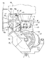
パージ装置38の構成についてさらに詳述すると、図5〜図10に示すごとく、集合ケース36の一側部(記録領域外であって近い側)に、吸引キャップ53が収納された昇降部材55が昇降動可能に装着されている(図9参照)。吸引キャップ53と吸引ポンプ54とは吸引チューブ61にて接続されている。図示しないが、被記録媒体である用紙Pの搬送のためのラインフイードモータを駆動源とし、駆動力切換手段を介して回転されるギヤ57によりカム体56が駆動される。このカム体56の一側面に形成された吸引昇降カム溝58に前記昇降部材55の足下端の摺動部55aが嵌合する一方、同じくカム体56の他側面と対峙して配置された吸引ポンプ54の2つのピストンロッドの下端係合部62a,63aは、前記カム体56の他側面に形成された2つのポンプカム溝59,60にそれぞれ嵌合し、カム体56が一回転する間に、昇降部材55が上昇して吸引キャップ53が記録ヘッド14のノズル部15に密接して、吸引ポンプ54の負圧にてインクの吸引を実行した後、吸引キャップ53が離れるように昇降部材55が下降する。
【0027】
ノズル払拭装置37は、前記パージ装置38に隣接し、且つ記録領域外であって近い側の集合ケース36内に配置され、軟質ゴム、軟質合成樹脂材等の弾性体からなる薄板状のワイパー体64を支持するワイパー昇降部材65の下端係合部65aは、前記カム体56の片面のワイパーカム溝66に嵌合し、カム体56が一回転する間に前記吸引キャップ53による所定のメインテナンス動作に同期して記録ヘッド14のノズル部15をワイパー体64で払拭する動作と昇降動作とを実行するものである。なお、インク吸引作業とワイパー作業とは、記録ヘッド14の複数のノズル部15について、1箇所ずつ行われる。
【0028】
この場合、図7に示すように、集合ケース36に配置されたロックレバー68は、その回動中心部68aの回りに回動自在であり、ロックレバー68の凸部68bが前記カム体56の外周カム面67(図9参照)に摺動するように、バネ69にて付勢されており、前記キャリッジ18がノズル部15の配置間隔毎に停止するとき、前記カム体56の所定の回転位相で、当該キャリッジ18の下面に形成された凹溝状の係合部18a(図6、図7参照)にロックレバー68の先端部68cが嵌まり係合して、キャリッジ18が移動しないように規制されている。
【0029】
上記のように、前記記録領域外に設けられたノズル払拭装置37及び吸引手段としてのパージ装置38に隣接して、ノズル部保護手段としての前記保存キャップ39及び保存キャップ移動手段としての移動部材40が配置されていると、長期間インクジェット記録装置2を使用しなかったとき、各ノズル部15にインクが詰まる等してインク吐出不良が発生していても、記録作業の開始のためキャリッジ18を少しだけ移動させるだけで、前記待機位置に隣接する吸引箇所に記録ヘッドを記録領域方向に、各ノズル部15の間隔毎に間欠移動させて、各ノズル部15のインク吐出不良のメインテナンスを実行でき、迅速に記録作業に移行できるという効果を奏する。
【0030】
また、移動部材40が吸引手段の方向に近づき移動するとき、自動的に各保存キャップ39が各ノズル部15から離れるように構成されているので、キャリッジ18を記録領域方向に移動させるのに、ロック解除のための余分の部品も必要がなく構成が簡単になるという効果を奏するものである。
なお、本発明に係るファクシミリ装置1は、操作パネル部6における各種キー操作に応じて入力される使用者からの各種指令に応じて、各種処理動作の設定、原稿読取ユニット5による原稿画像の読み取り、原稿画像の送信データ化、送信データの符号化、電話回線等の通信回線を介して他のファクシミリ装置に送信するファクシミリデータの送受信、受信データの復号化、復号化したファクシミリデータの記録ユニットでの用紙Pへの記録を実行するという通常のファクシミリ機能の他、原稿読取ユニット5のCIS(密着型イメージセンサ)34による原稿読取りと記録部の各ユニットによる用紙Pへカラー画像形成するというコピー(複写)処理機能、図示しないパーソナルコンピュータ等の外部装置からプリンタケーブルまたは赤外線等の無線を介して伝送されたプリントデータを受けて、そのデータに応じて用紙Pにカラー画像を形成するプリンタ処理機能、前記原稿読取ユニット5を使って読み取った画像データを前記外部装置へ送信するというスキャナ処理機能をも備えている。
【0031】
本発明は、インクジェット式の記録ヘッドを備えたプリンタにも適用できることはいうまでもない。
【0032】
【発明の効果】
以上に説明したように、請求項1に記載した発明の構成によれば、前記記録ヘッドの移動によって、前記記録ヘッドを搭載したキャリッジに設けられた突起部に押圧されて前記記録ヘッドの移動方向と同一方向に移動する被押圧部と、その被押圧部の移動に伴って前記保存キャップを前記記録ヘッドのノズル部に対してキャッピィングする方向に移動させる方向変換手段とを有するので、記録ヘッドもしくは記録ヘッドを搭載したキャリッジの移動に伴って保存キャップを記録ヘッドのノズル部に対してキャッピィングする方向に移動させるので、キャリッジの移動と保存キャップの記録ヘッド方向への移動の開始とが確実に同期して行われ、キャリッジと保存キャップの動作のタイミングを正確にすることができる。そして、保存キャップによるノズル部へのキャッピィングのために別途の駆動源を必要としないので装置の構成を簡素化し、且つコスト低減に寄与できるという効果を奏する。さらに、前記方向変換手段を介して前記保存キャップが前記記録ヘッドのノズル部にキャッピィングしたとき、前記突起部に押される前記被押圧部が、前記突起部と前記キャリッジに設けられた規制片との間に嵌まって挟持されるように構成されているので、保存キャップが前記ノズル部にキャッピィングしたとき、前記保存キャップが前記記録ヘッドもしくはキャリッジに対して相対移動するのを規制するので、インクジェット記録装置を運搬する等して揺り動かしても、前記各ノズル部に対して保存キャップがずれ移動せず、ノズル部の乾燥防止、保護を確実に行えるという効果を奏する。そして、被押圧部が突起部と規制片との間に嵌まって、保存キャップがノズル部を覆っている状態を保持するので、キャッピィング効果を失うことがない。また、キャリッジ側に突起部と規制片とを設けるだけの構成であるから構造が至極簡単で製造コストも高くならないという効果を奏する。
【0033】
また、請求項2に記載の発明によれば、前記被押圧部が前記突起部と前記規制片との間に嵌まり込む方向は、前記記録ヘッドのノズル部に前記保存キャップがキャッピィングする方向と交差しているので、前記キャリッジに設けた突起部にて移動部材が押されて、移動部材とキャリッジとが略同一方向に移動すると共に、方向変換手段により前記保存キャップを前記キャリッジの移動方向と略直交する方向に移動させて、保存キャップがノズル部を覆うように移動することができ、キャリッジの移動と保存キャップのキャッピィング動作とのタイミングが正確にでき、迅速且つ確実なキャッピィングを実行することができるという効果を奏する。
【0034】
【0035】
【0036】
【図面の簡単な説明】
【図1】 ファクシミリ装置の斜視図である。
【図2】 ファクシミリ装置の概略側断面図である。
【図3】 インクジェット記録装置の概略平面図である。
【図4】 インクジェット記録装置の側断面図である。
【図5】 メインテナンス部及び保存手段の平面図である。
【図6】 図5のVI−VI線矢視一部切欠き側面図である。
【図7】 図5のVII −VII 線矢視一部切欠き側面図である。
【図8】 図5の VIII −VIII矢視図である。
【図9】 カム体とノズル払拭装置、吸引手段、吸引ポンプとの係合関係を示す要部断面図である。
【図10】 移動部材が移動規制された状態を示すための、図8と同じ方向から見た一部切欠き図である。
【図11】 (a)はキャリッジが待機位置に接近したときの、突起部と被押圧部と規制片との関係を示す作用説明図、(b)は図11(a)のXIb−XIb線矢視図、(c)は保存キャップによるキャッピィング完了位置での、突起部と被押圧部と規制片との関係を示す作用説明図、(d)は図11(c)のXId−XId線矢視図である。
【符号の説明】
2 インクジェット記録装置
18 キャリッジ
14 記録ヘッド
15 ノズル部
35 保存手段
36 集合ケース
39 保存キャップ
40 移動部材
40a 回動基端部
41 丸軸
42 支持体
45 被押圧部
46 突起部
47 規制片
48 摺動片
49 カム板
50 引張バネ[0001]
BACKGROUND OF THE INVENTION
The present invention relates to a recording apparatus for forming an image on a recording medium in a facsimile machine or a copying machine, and more particularly, to prevent the nozzle portion of an ink jet recording head from drying when waiting. It relates to the structure of the storage means.
[0002]
[Prior art]
2. Description of the Related Art Conventionally, in an image forming apparatus such as a facsimile machine or a copying machine, a recording unit for ejecting ink is well known as a recording unit for forming an image on a sheet as a recording medium.
In order to prevent ink discharge failure from occurring due to drying of the nozzle portion of this type of recording head and to maintain the state of the recording head satisfactorily, for example, it is disclosed in Japanese Patent Laid-Open No. 9-14185. As described above, the carriage on which the recording head is mounted is configured to be able to reciprocate in a direction perpendicular to the conveyance direction of the recording medium, while a storage cap is mounted at a standby position outside the recording area on the recording medium. The moving member is supported so as to be able to move substantially parallel to the moving direction of the carriage, and to be rotatable so that the storage cap contacts and separates from the nozzle portion of the recording head. Is spring-biased in a direction approaching the recording area. Then, as the carriage moves toward the standby position, the moving member is pushed against the urging force of the spring, and at this time, the moving member is rotated by a cam member as direction changing means. In addition, when the storage cap approaches the nozzle portion of the recording head and the recording head stops at a predetermined standby position, a configuration is known in which the storage cap is synchronized so that the storage cap is completely covered. .
[0003]
[Problems to be solved by the invention]
However, in the above configuration, since the moving member is only pressed in one direction by the biasing spring with respect to the carriage stopped at the standby position, the moving member can move in a direction opposite to the pressing direction. Therefore, when an external force is applied to the apparatus, such as when transporting this type of ink jet recording apparatus, or when the apparatus is tilted in a direction in which the moving member is separated from the carriage, the storage cap is detached from the nozzle portion. As a result, there has been a problem that the nozzle portion of the recording head cannot be used to prevent drying and maintain.
[0004]
The present invention has been made in order to solve the above-described conventional problems, and provides an ink jet recording apparatus that can maintain a state in which a storage cap is put on the nozzle portion of the recording head regardless of external force applied to the apparatus. It is intended to provide.
[0005]
[Means for Solving the Problems]
In order to achieve this object, an ink jet recording apparatus according to a first aspect of the present invention is an ink jet recording apparatus that performs recording on a recording medium by reciprocating a recording head that ejects ink. A storage cap for preventing ink drying, and a pressed object that moves in the same direction as the movement direction of the recording head by being pressed by a protrusion provided on a carriage on which the recording head is mounted by the movement of the recording head And a direction changing means for moving the storage cap in the direction of capping with respect to the nozzle portion of the recording head as the pressed part moves, and the storage cap is moved to the recording head via the direction changing means. carry when Kyappyingu to the nozzle portion, the pressed portion to be pressed by the protrusion, and the protrusion the Those that are configured to be sandwiched fits between the regulating piece provided in the di.
[0006]
According to a second aspect of the present invention, in the ink jet recording apparatus according to the first aspect, the direction in which the pressed portion fits between the protrusion and the restricting piece is the nozzle portion of the recording head. Further, the storage cap intersects with the capping direction.
[0007]
[0008]
[0009]
DETAILED DESCRIPTION OF THE INVENTION
Next, an embodiment of the present invention will be described with reference to the drawings. 1 is a perspective view of a facsimile apparatus 1 having an
[0010]
As shown in FIGS. 1 and 2, the main body case of the facsimile apparatus 1 accommodates the ink
[0011]
One end of the metal bracket is locked, the coil portion is wound around the outer periphery of the cylindrical shaft portion 4, and the other end is locked at an appropriate location such as a metal chassis in the
[0012]
Further, a
[0013]
The lower surface of the main
[0014]
As shown in FIG. 2, in the unit case 5a of the
[0015]
The paper P stacked on the paper feed cassette 3 is separated from a rotating paper feed roller that rotates intermittently as a paper feed mechanism having a well-known structure (not shown) disposed in the rear portion of the main
[0016]
As shown in FIGS. 2, 3, 4, and 5, the
[0017]
The
[0018]
Next, details of the configuration of the
[0019]
That is, a synthetic resin frame-shaped moving
[0020]
Then, one of the rotation
[0021]
When the
[0022]
Further, a
When the pressed
[0023]
As shown in FIG. 10, when moving further upward along the sliding
[0024]
As can be understood from the above description, when returning from the standby position in the direction opposite to the arrow A and returning to the recording area, the urging force of the
[0025]
Next, the configuration of a nozzle wiping device (wiper device) 37 and a
[0026]
The configuration of the
[0027]
The
[0028]
In this case, as shown in FIG. 7, the
[0029]
As described above, adjacent to the
[0030]
Further, since each
The facsimile apparatus 1 according to the present invention sets various processing operations and reads a document image by the
[0031]
Needless to say, the present invention can also be applied to a printer having an ink jet recording head.
[0032]
【The invention's effect】
As described above, according to the configuration of the first aspect of the present invention, the movement of the recording head is caused by the movement of the recording head and is pressed by the protrusion provided on the carriage on which the recording head is mounted. And a direction changing means for moving the storage cap in the direction of capping with respect to the nozzle portion of the recording head as the pressed portion moves, so that the recording head or The storage cap is moved in the capping direction with respect to the nozzle portion of the recording head as the carriage mounting the recording head is moved, so that the movement of the carriage and the start of movement of the storage cap in the recording head direction are surely synchronized. Thus, the timing of the operation of the carriage and the storage cap can be made accurate. In addition, since a separate drive source is not required for capping the nozzle portion with the storage cap, the configuration of the apparatus can be simplified and the cost can be reduced. Further, when the storage cap is capped to the nozzle portion of the recording head via the direction changing means, the pressed portion to be pressed by the protruding portion is formed between the protruding portion and the restriction piece provided on the carriage . Since the storage cap is configured to be fitted and sandwiched between the nozzles, the storage cap restricts the relative movement of the storage cap with respect to the recording head or the carriage. Even if the apparatus is moved and swung, the storage cap does not move with respect to each nozzle part, and the nozzle part can be prevented from drying and protected. And since a to-be-pressed part fits between a projection part and a control piece and the state which the storage cap has covered the nozzle part is hold | maintained, a capping effect is not lost. In addition, since the configuration is such that only the protrusion and the regulating piece are provided on the carriage side, the structure is extremely simple and the manufacturing cost is not increased.
[0033]
According to the second aspect of the present invention, the direction in which the pressed portion fits between the protrusion and the restricting piece is a direction in which the storage cap caps the nozzle portion of the recording head. Since they intersect, the moving member is pushed by the projection provided on the carriage so that the moving member and the carriage move in substantially the same direction, and the storage cap is moved in the direction of movement of the carriage by the direction changing means. The storage cap can be moved so as to cover the nozzle portion by moving in a substantially orthogonal direction, the timing of the carriage movement and the storage cap capping operation can be accurately performed, and quick and reliable capping can be performed. There is an effect that can be.
[0034]
[0035]
[0036]
[Brief description of the drawings]
FIG. 1 is a perspective view of a facsimile apparatus.
FIG. 2 is a schematic sectional side view of a facsimile apparatus.
FIG. 3 is a schematic plan view of the ink jet recording apparatus.
FIG. 4 is a side sectional view of the ink jet recording apparatus.
FIG. 5 is a plan view of a maintenance unit and storage means.
6 is a partially cutaway side view taken along the line VI-VI in FIG. 5;
7 is a partially cutaway side view taken along the line VII-VII in FIG. 5;
8 is a view taken along arrow VIII-VIII in FIG. 5;
FIG. 9 is a cross-sectional view of an essential part showing an engagement relationship between a cam body, a nozzle wiping device, suction means, and a suction pump.
FIG. 10 is a partially cutaway view seen from the same direction as FIG. 8 for showing a state in which the movement member is restricted in movement.
11A is an operation explanatory diagram showing the relationship among the protruding portion, the pressed portion, and the regulating piece when the carriage approaches the standby position, and FIG. 11B is a line XIb-XIb in FIG. 11A. An arrow view, (c) is an action explanatory view showing a relation between a projection part, a pressed part, and a regulating piece at a capping completion position by a storage cap, and (d) is an Xid-XId line arrow of FIG. 11 (c). FIG.
[Explanation of symbols]
DESCRIPTION OF
Claims (2)
前記記録ヘッドのノズル部のインクの乾燥を防止するための保存キャップと、
前記記録ヘッドの移動によって、前記記録ヘッドを搭載したキャリッジに設けられた突起部に押圧されて前記記録ヘッドの移動方向と同一方向に移動する被押圧部と、
その被押圧部の移動に伴って前記保存キャップを前記記録ヘッドのノズル部に対してキャッピィングする方向に移動させる方向変換手段と、
前記方向変換手段を介して前記保存キャップが前記記録ヘッドのノズル部にキャッピィングしたとき、前記突起部に押される前記被押圧部が、前記突起部と前記キャリッジに設けられた規制片との間に嵌まって挟持されるように構成されていることを特徴とするインクジェット記録装置。In an inkjet recording apparatus that performs recording on a recording medium by reciprocating a recording head that ejects ink,
A storage cap for preventing drying of ink in the nozzle portion of the recording head;
A pressed portion that moves in the same direction as the moving direction of the recording head by being pressed by a protrusion provided on a carriage on which the recording head is mounted by the movement of the recording head;
Direction changing means for moving the storage cap with respect to the nozzle portion of the recording head in accordance with the movement of the pressed portion;
When the storage cap via the direction changing means has Kyappyingu the nozzle portion of the recording head, the pressed portion to be pressed by the protrusions, between the regulating piece provided in the said projecting portion carriage An inkjet recording apparatus configured to be fitted and sandwiched.
Priority Applications (1)
| Application Number | Priority Date | Filing Date | Title |
|---|---|---|---|
| JP20625998A JP4174635B2 (en) | 1998-07-22 | 1998-07-22 | Inkjet recording device |
Applications Claiming Priority (1)
| Application Number | Priority Date | Filing Date | Title |
|---|---|---|---|
| JP20625998A JP4174635B2 (en) | 1998-07-22 | 1998-07-22 | Inkjet recording device |
Publications (2)
| Publication Number | Publication Date |
|---|---|
| JP2000037887A JP2000037887A (en) | 2000-02-08 |
| JP4174635B2 true JP4174635B2 (en) | 2008-11-05 |
Family
ID=16520380
Family Applications (1)
| Application Number | Title | Priority Date | Filing Date |
|---|---|---|---|
| JP20625998A Expired - Fee Related JP4174635B2 (en) | 1998-07-22 | 1998-07-22 | Inkjet recording device |
Country Status (1)
| Country | Link |
|---|---|
| JP (1) | JP4174635B2 (en) |
Families Citing this family (3)
| Publication number | Priority date | Publication date | Assignee | Title |
|---|---|---|---|---|
| JP4689199B2 (en) * | 2004-06-23 | 2011-05-25 | 株式会社リコー | Image forming apparatus |
| JP4920903B2 (en) * | 2005-05-12 | 2012-04-18 | キヤノン株式会社 | Inkjet recording device |
| JP6020136B2 (en) * | 2012-12-20 | 2016-11-02 | セイコーエプソン株式会社 | Liquid ejecting apparatus and liquid ejecting method |
-
1998
- 1998-07-22 JP JP20625998A patent/JP4174635B2/en not_active Expired - Fee Related
Also Published As
| Publication number | Publication date |
|---|---|
| JP2000037887A (en) | 2000-02-08 |
Similar Documents
| Publication | Publication Date | Title |
|---|---|---|
| US6690494B1 (en) | Tension adjustable mechanism for reciprocatingly moving print/read head device | |
| JP2006231560A (en) | Image forming apparatus | |
| JP3858998B2 (en) | Image forming apparatus | |
| US7807926B2 (en) | Flexible cable harness and image forming apparatus | |
| JP3970097B2 (en) | Recording device | |
| JP3767568B2 (en) | Image forming apparatus | |
| JP4174635B2 (en) | Inkjet recording device | |
| JP3931981B2 (en) | Image forming apparatus | |
| JP2000062199A (en) | Ink jet recording device | |
| US7520587B2 (en) | Image recording apparatus | |
| JP2003053999A (en) | Image forming device | |
| JP2023095336A (en) | Sheet feeding device and recording device | |
| JP3674325B2 (en) | Inkjet recording device | |
| JP3420513B2 (en) | Sheet conveying device and image reading / recording device provided with the device | |
| JP4496871B2 (en) | Inkjet printer | |
| JP2003053947A (en) | Image forming device | |
| JP3514126B2 (en) | Image forming device | |
| JP2000062200A (en) | Mounting device for maintenance unit | |
| JP2007119233A (en) | Image recording device | |
| JP3901478B2 (en) | Unit connecting device, recording device | |
| JP4157992B2 (en) | Inkjet recording device | |
| JP4600465B2 (en) | Carriage and image forming apparatus | |
| JP2006327804A (en) | Image recording device | |
| JPH0918642A (en) | Image information processing device | |
| JP2000032193A (en) | Image forming device |
Legal Events
| Date | Code | Title | Description |
|---|---|---|---|
| A621 | Written request for application examination |
Free format text: JAPANESE INTERMEDIATE CODE: A621 Effective date: 20050722 |
|
| A977 | Report on retrieval |
Free format text: JAPANESE INTERMEDIATE CODE: A971007 Effective date: 20071106 |
|
| A131 | Notification of reasons for refusal |
Free format text: JAPANESE INTERMEDIATE CODE: A131 Effective date: 20071121 |
|
| A521 | Written amendment |
Free format text: JAPANESE INTERMEDIATE CODE: A523 Effective date: 20071225 |
|
| A131 | Notification of reasons for refusal |
Free format text: JAPANESE INTERMEDIATE CODE: A131 Effective date: 20080514 |
|
| A521 | Written amendment |
Free format text: JAPANESE INTERMEDIATE CODE: A523 Effective date: 20080623 |
|
| TRDD | Decision of grant or rejection written | ||
| A01 | Written decision to grant a patent or to grant a registration (utility model) |
Free format text: JAPANESE INTERMEDIATE CODE: A01 Effective date: 20080723 |
|
| A01 | Written decision to grant a patent or to grant a registration (utility model) |
Free format text: JAPANESE INTERMEDIATE CODE: A01 |
|
| A61 | First payment of annual fees (during grant procedure) |
Free format text: JAPANESE INTERMEDIATE CODE: A61 Effective date: 20080805 |
|
| FPAY | Renewal fee payment (event date is renewal date of database) |
Free format text: PAYMENT UNTIL: 20110829 Year of fee payment: 3 |
|
| R150 | Certificate of patent or registration of utility model |
Free format text: JAPANESE INTERMEDIATE CODE: R150 |
|
| FPAY | Renewal fee payment (event date is renewal date of database) |
Free format text: PAYMENT UNTIL: 20120829 Year of fee payment: 4 |
|
| FPAY | Renewal fee payment (event date is renewal date of database) |
Free format text: PAYMENT UNTIL: 20120829 Year of fee payment: 4 |
|
| FPAY | Renewal fee payment (event date is renewal date of database) |
Free format text: PAYMENT UNTIL: 20130829 Year of fee payment: 5 |
|
| LAPS | Cancellation because of no payment of annual fees |