JP4174079B2 - Two-phase hydrotreatment - Google Patents
Two-phase hydrotreatment Download PDFInfo
- Publication number
- JP4174079B2 JP4174079B2 JP50500399A JP50500399A JP4174079B2 JP 4174079 B2 JP4174079 B2 JP 4174079B2 JP 50500399 A JP50500399 A JP 50500399A JP 50500399 A JP50500399 A JP 50500399A JP 4174079 B2 JP4174079 B2 JP 4174079B2
- Authority
- JP
- Japan
- Prior art keywords
- hydrogen
- reactor
- feed
- diluent
- liquid
- Prior art date
- Legal status (The legal status is an assumption and is not a legal conclusion. Google has not performed a legal analysis and makes no representation as to the accuracy of the status listed.)
- Expired - Fee Related
Links
Images


Classifications
-
- C—CHEMISTRY; METALLURGY
- C10—PETROLEUM, GAS OR COKE INDUSTRIES; TECHNICAL GASES CONTAINING CARBON MONOXIDE; FUELS; LUBRICANTS; PEAT
- C10G—CRACKING HYDROCARBON OILS; PRODUCTION OF LIQUID HYDROCARBON MIXTURES, e.g. BY DESTRUCTIVE HYDROGENATION, OLIGOMERISATION, POLYMERISATION; RECOVERY OF HYDROCARBON OILS FROM OIL-SHALE, OIL-SAND, OR GASES; REFINING MIXTURES MAINLY CONSISTING OF HYDROCARBONS; REFORMING OF NAPHTHA; MINERAL WAXES
- C10G47/00—Cracking of hydrocarbon oils, in the presence of hydrogen or hydrogen- generating compounds, to obtain lower boiling fractions
-
- C—CHEMISTRY; METALLURGY
- C10—PETROLEUM, GAS OR COKE INDUSTRIES; TECHNICAL GASES CONTAINING CARBON MONOXIDE; FUELS; LUBRICANTS; PEAT
- C10G—CRACKING HYDROCARBON OILS; PRODUCTION OF LIQUID HYDROCARBON MIXTURES, e.g. BY DESTRUCTIVE HYDROGENATION, OLIGOMERISATION, POLYMERISATION; RECOVERY OF HYDROCARBON OILS FROM OIL-SHALE, OIL-SAND, OR GASES; REFINING MIXTURES MAINLY CONSISTING OF HYDROCARBONS; REFORMING OF NAPHTHA; MINERAL WAXES
- C10G45/00—Refining of hydrocarbon oils using hydrogen or hydrogen-generating compounds
- C10G45/02—Refining of hydrocarbon oils using hydrogen or hydrogen-generating compounds to eliminate hetero atoms without changing the skeleton of the hydrocarbon involved and without cracking into lower boiling hydrocarbons; Hydrofinishing
- C10G45/22—Refining of hydrocarbon oils using hydrogen or hydrogen-generating compounds to eliminate hetero atoms without changing the skeleton of the hydrocarbon involved and without cracking into lower boiling hydrocarbons; Hydrofinishing with hydrogen dissolved or suspended in the oil
-
- C—CHEMISTRY; METALLURGY
- C10—PETROLEUM, GAS OR COKE INDUSTRIES; TECHNICAL GASES CONTAINING CARBON MONOXIDE; FUELS; LUBRICANTS; PEAT
- C10G—CRACKING HYDROCARBON OILS; PRODUCTION OF LIQUID HYDROCARBON MIXTURES, e.g. BY DESTRUCTIVE HYDROGENATION, OLIGOMERISATION, POLYMERISATION; RECOVERY OF HYDROCARBON OILS FROM OIL-SHALE, OIL-SAND, OR GASES; REFINING MIXTURES MAINLY CONSISTING OF HYDROCARBONS; REFORMING OF NAPHTHA; MINERAL WAXES
- C10G65/00—Treatment of hydrocarbon oils by two or more hydrotreatment processes only
- C10G65/02—Treatment of hydrocarbon oils by two or more hydrotreatment processes only plural serial stages only
- C10G65/04—Treatment of hydrocarbon oils by two or more hydrotreatment processes only plural serial stages only including only refining steps
- C10G65/08—Treatment of hydrocarbon oils by two or more hydrotreatment processes only plural serial stages only including only refining steps at least one step being a hydrogenation of the aromatic hydrocarbons
Abstract
Description
発明の背景
本発明は水素ガスを触媒を通して循環させる必要のない2相水素化処理方法に関する。この方法は水素の溶解度が油供給物に比較して高い溶媒又は希釈剤の存在下で水素及び処理される油を混合及び/又はフラッシングすることにより達成される。また本発明は水素化分解(hydrocracking)、ハイドロ異性化(hydroisomerization)、水素化脱金属(hydrodemetalization)に関する。
水素化加工(hydrotreating)、水素化仕上げ(hydrofinishing)、水素化精製(hydrorefining)、及び水素化分解(hydrocracking)を含む水素化処理(hydroprocessing)において、硫黄、窒素、酸素、金属、又はその他の汚染物を飽和又は除去するか、又は分子量を減少させる(クラッキング)ために、水素を石油留分、留出物、残油と反応させる触媒が使用される。特殊な表面特性を有する触媒が所望の反応を達成するのに必要な活性を得るために求められる。
従来の水素化処理においては、水素が触媒の表面で石油分子との反応に利用されるように水素を気相から液相に移すことが必要である。これは大容量の水素ガスと油を触媒床を通して循環させることにより達成される。油と水素は触媒床を通って流れ、そして水素は触媒上に分布する油の薄膜中に吸収される。水素の必要量は液体の1000〜5000SCF/bblのように大きいため、反応器は非常に大きくなり、そして極めて厳しい状態、即ち2〜3百psiから5000psiもの大きな圧力で、また約204.44-482.22℃(400−900°F)の温度で操業される。
従来の処理方法は米国特許No.4,698,147(マッコナジー(McConaghy,Jr.)1987年10月6日特許許可)に示され、これは“短い滞留時間の水素ドナー希釈剤分解方法”を開示する。この米国特許は水素を分解(クラッキング)プロセスに供給するために入力フローをドナー希釈剤と混合する。分解プロセスの後に、混合物を生成物と使用済み希釈剤に分離し、使用済み希釈剤を部分水素添加によって再生し、そして分解工程のための入力フローに戻す。この米国特許は分解に必要な水素を放出するために、プロセスを通じてドナー希釈剤の化学的性質を実質的に変化させることに注目すべきである。またこの米国特許の方法はカーボン付着に基づく温度上限及び増大した灯用ガスの製造によって制限され、その結果、プロセスの最大分解温度に経済的な制限が課せられる。
米国特許No.4,857,168(久保等、1989年8月15日特許許可)は“重質留分油の水素化分解方法”を開示する。この米国特許は触媒促進分解法に水素を供給するためにドナー希釈剤及び水素ガスの両方を使用する。この米国特許は重質留分油、ドナー溶媒、水素ガス、及び触媒を適切に供給すると触媒上へのコークスの生成が抑制され、そしてコークスの生成が実質的に又は完全に除去されることを開示する。この米国特許は触媒を有する分解反応器と触媒を有する別の水素添加反応器を必要とする。この米国特許はまた反応プロセスに水素を供給するためにドナー希釈剤の分解を必要とする。
上記従来技術は水素ガスの添加が必要であること及び/又は分解プロセスに使用されるドナー溶媒を再水素添加する複雑な工程を必要とする。従って、改良されそして簡易化された水素化処理法及び装置が求められている。
発明の概要
本発明によれば、水素ガスを触媒を通して循環させる必要がない方法が開発された。この方法は水素の溶解度が油供給物に比較して高い溶媒又は希釈剤の存在下で水素及び処理される油を混合及び/又はフラッシングして水素を溶解することにより達成される。
水素化処理反応に必要とされる水素の全てが溶解して利用されるように、加えられる希釈剤の種類と量及び反応器の状態を調整できる。油/希釈剤/水素の溶液をプラグ流れ(plug flow)又は管状反応器のような触媒が充填された反応器に供給して油及び水素を反応させることができる。追加の水素は必要でないため、水素の再循環は回避され、そして反応器の散水床(trickle bed)操作は回避される。従って大型の散水床反応器をより小さな反応器に置換できる(図1、2及び3を参照)。
また本発明は水素化分解、ハイドロ異性化(hydroisomerization)、ハイドロ脱金属(hydrodemetalization)等に関する。上述したように、水素ガスは再循環された水素化分解生成物、異性化生成物、又は再循環された脱金属化生成物のような希釈剤と供給原料に混合及び/又はフラッシングされることにより、水素が溶解され、次いでこの混合物は触媒上に通される。
本発明の主目的は改良された2相水素化処理システム、プロセス、方法及び/又は装置を提供することである。
本発明の他の目的は改良された水素化分解プロセス、ハイドロ異性化プロセス、フィッシャー-トロプシュプロセス、及び/又はハイドロ脱金属プロセスを提供することである。
本発明の他の目的及び応用の範囲は以下の詳細な説明、添付の図面、ここで同じ部分は同じ参照番号で示される、から明らかになるであろう。
【図面の簡単な説明】
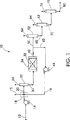
図1はディーゼル油の水素化装置の概略的な方法のフローダイヤグラムである。
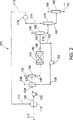
図2は残油の水素化装置の概略的な方法のフローダイヤグラムである。
図3は水素化処理システムの概略的な方法のフローダイヤグラムである。
図4は多段反応器システムの概略的な方法のフローダイヤグラムである。
図5は1200BPSD水素化処理装置の概略的な方法のフローダイヤグラムである。
発明の詳細な記述
我々は水素ガス又は分離水素相を触媒を通して循環させる必要のない方法を発明した。この方法は水素及び処理される油を水素の溶解度が比較的高い溶媒又は希釈剤の存在下で混合及び/又はフラッシングして水素を溶解することにより達成される。
水素化処理反応に必要とされる水素の全てが溶解して利用されるように、加えられる希釈剤の種類と量及び反応器の状態を調整できる。油/希釈剤/水素の溶液をプラグ流れ反応器、管状反応器、又は触媒が充填されたその他の反応器に供給して油及び水素を反応させることができる。追加の水素は必要でないため、水素の再循環は回避され、そして反応器の散水床操作は回避される。従って大型の散水床反応器をより小さな又は簡単な反応器に置換できる(図1、2及び3を参照)。
より小さな又は簡単な反応器を使用することに加えて、水素再循環圧縮機の使用を回避できる。反応に必要な水素の全てを反応器への供給に先立って溶けた状態で利用できるため、水素ガスを反応器内で循環させる必要はなく、又循環圧縮機も必要がない。循環圧縮機及びプラグ流れ反応器又は管状反応器を使用する必要がないため、水素化処理プロセスの主要なコストを大幅に低減できる。
水素化処理で生じる反応の多くは非常に発熱的であるため、多量の熱が反応器中で発生する。反応器の温度は再循環流を用いて制御できる。反応器流出物の制御された量を反応器の前部に再循環させて新鮮な供給物と水素に混合できる。再循環流は熱を吸収して反応器の温度上昇を押さえる。反応器の温度は新鮮な供給物の温度及び再循環物の量を制御することにより制御できる。また再循環流は既に反応した分子を含んでいるため、不活性希釈剤として作用する。
水素化処理が有する大きな問題の一つは触媒のコーキング(コークス化)である。反応条件は極めて厳しいため、触媒の表面で分解が生じる。用いる水素の量が不十分な場合には、分解によりコークスが生成して触媒を失活させる。水素化処理のために本発明を用いて、分解反応が生じる場合、常に十分な水素が溶解して利用されるため、コーキングはほとんど発生しない。その結果、触媒の寿命は増大し、操業及び維持のコストは減少する。
図1は数字10で概略的に示されるディーゼル油の水素化装置のための概略的な方法のフローダイヤグラムを示す。新鮮な供給原料12を供給装填ポンプ14で結合領域18に送り込む。次いで新鮮な供給原料12を水素15及び水素化処理された供給物16に結合して新鮮な供給物混合物20を形成する。混合物20を次いで分離器22で分離して第1分離器廃ガス24と分離混合物30を形成する。分離混合物30を反応器34中の触媒32と結合して反応混合物40を形成する。反応混合物40を2つの生成物の流れであるリサイクルフロー42と継続フロー50に分離する。リサイクルフロー42はリサイクルポンプ44で圧送されて水素化処理された供給物16になり、これは新鮮な供給原料12及び水素15に結合する。
継続フロー50は分離器52に流入し、ここで第2の分離器廃ガス54が除去されて反応した分離フロー60を生成する。反応分離フロー60は次いでフラッシャ62に流入してフラッシャ廃ガス64及び反応し分離しフラッシュしたフロー70を生成する。この反応分離フラッシュしたフロー70は次いでストリッパー72内に圧送され、ここでストリッパー廃ガス74が除去されて出力生成物80を形成する。
図2は数字100で概略的に示される残油の水素化装置のための概略的な方法のフローダイヤグラムを示す。新鮮な供給原料110を結合領域114で溶媒112と結合して、結合した溶媒供給物120を形成する。結合した溶媒供給物120を溶媒供給物装填ポンプ122で結合領域124に送り込む。次いで結合した溶媒供給物120を水素126及び水素化処理された供給物128に結合して水素-溶媒-供給物混合物130を形成する。水素-溶媒-供給物混合体130を次いで第1分離器132で分離して第1分離器廃ガス134と分離混合物140を形成する。分離混合物140を反応器144中の触媒142と結合して反応混合物150を形成する。反応混合物150を2つの生成物の流れであるリサイクルフロー152と継続フロー160に分離する。リサイクルフロー152はリサイクルポンプ154で圧送されて水素化処理された供給物128になり、これは溶媒供給物120及び水素126に結合する。
継続フロー160は第2分離器162に流入し、ここで第2の分離器廃ガス164が除去されて反応した分離フロー170を生成する。反応分離フロー170は次いでフラッシャ172に流入してフラッシャ廃ガス174及び反応し分離しフラッシュしたフロー180を生成する。フラッシャ廃ガス174は冷却器176で冷却されて溶媒112を生成し、これは導入される新鮮な供給物110と結合する。
反応し分離されフラッシュされたフロー180はストリッパー182に流入し、ここでストリッパー廃ガス184が除去されて出力生成物190を生成する。
図3は数字200で概略的に示される水素化処理装置のための概略的な方法のフローダイヤグラムを示す。
新鮮な供給原料202を第1結合領域206で第1希釈剤204と結合して、第1希釈剤-供給物208を形成する。次いで第1希釈剤-供給物208を第2結合領域212で第2希釈剤210と結合して第2希釈剤-供給物214を形成する。第2希釈剤-供給物214を次いで希釈剤-供給物装填ポンプ216で第3結合領域218に圧送する。
水素220を水素圧縮機222に入れて圧縮水素224を調製する。圧縮水素224は第3結合領域218に流れる。
第2希釈剤-供給物214と圧縮水素224は第3結合領域218で結合して水素-希釈剤-供給物混合体226を形成する。水素-希釈剤-供給物混合体226は次いで供給物-生成物交換機228に通され、ここで第3分離器排ガス230を用いて加温され、第1交換機フロー232を生成する。第1交換機フロー232と第1リサイクルフロー234は第4結合領域236で結合して第1リサイクル供給物238を形成する。
第1リサイクル供給物238は次いで第1供給物-生成物交換機240に通され、ここで交換された第1整流器交換排ガス242を用いて加温され、第2交換機フロー244を生成する。第2交換機フロー244と第2リサイクルフロー246は第5結合領域248で結合して第2リサイクル供給物250を生成する。
第2リサイクル供給物250は次いで供給物-リサイクル混合機252中で混合されて供給物-リサイクル混合物254を形成する。供給物-リサイクル混合物254は次いで反応器入口分離機256に流入する。
供給物-リサイクル混合物254は反応器入口分離機256中で分離されて、反応器入口分離機廃ガス258と入口分離された混合物260を形成する。反応器入口分離機廃ガス258は燃焼されるか、又は本システム200から除去される。
入口分離された混合物260は反応器264内で触媒262と結合して反応した混合物266を形成する。反応混合物266は反応器の出口の分離機268に流入する。
反応混合物266は反応器出口分離機268内で分離されて、反応器出口分離機廃ガス270と出口分離された混合物272を形成する。反応器出口分離機廃ガス270は反応器出口分離機268から流出して燃焼されるか、又は本装置200から除去される。
出口分離された混合物272は反応器出口分離機268から流出し、そして第1分割領域278で大リサイクルフロー274と継続出口分離された混合物276に分割される。
大リサイクルフロー274はリサイクルポンプ280を通って第2分割領域282に圧送される。大リサイクルフロー274は第2分割領域282で上述したように用いられている第1リサイクルフロー234と第2リサイクルフロー246に分割される。
継続出口分離された混合物276は第1分割領域278を出た後、流出液加熱器284に流入して、加熱された流出液フロー286になる。
加熱された流出液フロー286は第1整流器288に流入し、ここで第1整流器排気ガス290と第1整流器フロー292に分割される。第1整流器排気ガス290と第1整流器フロー292は別々に第2交換機294に流入し、ここでこれらの温度差が低減される。
この交換機は第1整流器排気ガス290を上述した第1供給物-生成物交換機240に流入する第1整流器交換排気ガス242に変換する。第1供給物-生成物交換機240は第1整流器交換排気ガス242を均等に冷却して第1の二重冷却された排気ガス296を形成する。
第1の二重冷却排気ガス296は次いで冷却器298で冷却されて第1の冷却された排気ガス300になる。第1の冷却された排気ガス300は次いで還流アキュムレータ302に流入し、そこで排気ガス301と第1の希釈剤204に分割される。排気ガス301は本システム200から排気される。第1希釈剤204は第1結合領域206に流れて上述したように新鮮な供給原料202に結合する。
上記交換機は第1整流器フロー292を第3分離機308に流入する第1整流器変換フロー306に変換する。第3分離機308は第1整流器変換フロー306を第3分離機排気ガス230と第2の整流されたフロー310に分割する。
第3分離機排気ガス230は前述したように交換機228に流れる。交換機228は第3分離機排気ガス230を冷却して第2の冷却された排気ガス312を形成する。
第2の冷却された排気ガス312は次いで冷却器314で冷却されて第3の冷却された排気ガス316になる。第3の冷却された排気ガス316は次いで還流アキュムレータ318に流入し、そこで還流アキュムレータ排気ガス320と第2の希釈剤210に分割される。還流アキュムレータ排気ガス320は本システム200から排気される。第2希釈剤210は第2結合領域212に流れて前述のように本システム200に再結合する。
第2の整流されたフロー310は第2整流器322に流入し、そこで第3の整流器排気ガス324と第1の末端フロー326に分割される。第1末端フロー326は次いで使用又は更に処理するために本システム200から出る。第3の整流器排気ガス324は冷却器328に流入し、そこで冷却されて第3の冷却された排気ガス330になる。
第3の冷却された排気ガス330は冷却器328から第4の分離機332に流入する。第4分離機332は第3の冷却された排気ガス330を第4分離機排気ガス334と第2の末端フロー336に分割する。第4分離機排気ガス334は本システム200から排出される。第2末端フロー336は次いで使用又は更に処理するために本システム200から出る。
図4は数字400で概略的に示される1200BPSD水素化処理装置のための概略的な方法のフローダイヤグラムを示す。
新鮮な供給原料401を約126.66℃(260°F)、20psi、及び1200BBL/Dの許容入力パラメーターのための第1監視点402で監視する。新鮮な供給原料401を次いで第1結合領域406で希釈剤404と結合して、結合した希釈剤-供給物408を形成する。結合した希釈剤-供給物408を第1監視オリフィス412及び第1バルブ414を通って希釈剤-供給物装填ポンプ410で第2結合領域416に圧送する。
水素420を37.77℃(100°F)、500psi、及び40000SCF/HRのパラメーターで水素圧縮機422中に導入して圧縮水素424を造る。水素圧縮機422は水素420を1500psiまで圧縮する。圧縮された水素424は第2監視点426に流され、ここで許容入力パラメーターのために監視される。圧縮水素424を第2監視オリフィス428及び第2バルブ430を通って第2結合領域416に流す。
第1監視オリフィス412、第1バルブ414及びFFIC434は結合した希釈剤-供給物408の第2結合領域416への流入フローを制御するFIC432に接続する。同様に、第2監視オリフィス428、第2バルブ430及びFIC432は圧縮水素424の第2結合領域416への流入フローを制御するFFIC434に接続する。結合した希釈剤-供給物408と圧縮水素424は第2結合領域416で結合して、水素-希釈剤-供給物の混合物440を形成する。この混合物のパラメーターは約1500psi及び2516BBL/Dであり、これは第4監視点442で監視される。水素-希釈剤-供給物の混合物440は次いで供給物-生成物交換機444に流入し、ここで整流された生成物610を用いて加温されて交換機フロー446を生成する。供給物-生成物交換機444は約2.584MMBTU/HRで作動する。
交換機フロー446は第5監視点448で監視されて、交換機フロー446のパラメーターに関する情報が集められる。
交換機フロー446は次いで交換機フロー446を5.0MMBTU/HRで加熱することのできる反応器予熱器450に入り、予熱されたフロー452を生成する。予熱されたフロー452は第6監視点454及びTIC456で監視される。
燃料ガス458は第3バルブ460を通って流れ、そしてこの燃料を反応器予熱器450に供給するためにPIC462により監視される。PIC462は第3バルブ460及びTIC456に接続する。
予熱されたフロー452は第3結合領域466で再循環フロー464と結合して予熱された再循環フロー468を形成する。予熱された再循環フロー468は第7監視点470で監視される。予熱された再循環フロー468は次いで供給物-再循環ミキサー472で混合されて、供給物-再循環混合物474を形成する。供給物-再循環混合物474は次いで反応器入口分離機476に流入する。反応器入口分離機476は152.4cm I.D.x3.048m-0cm S/S(60″I.D.x 10′0″ S/S)のパラメーターを有する。
供給物-再循環混合物474は反応器入口分離機476中で分離されて反応器入口分離機廃ガス478と入口分離された混合物480を形成する。反応器入口分離機廃ガス478はFI484に接続する第3監視オリフィス482を通って反応器入口分離機476から流出する。反応器入口分離機廃ガス478は次いで第4バルブ486を通って流れ、第8監視点488を通過し、そして燃焼されるか、又は本システム400から除去される。
LIC490は第4バルブ486と反応器入口分離機476の両方に接続する。入口分離された混合物480は第9監視点500で監視される約310℃(590°F)及び1500psiのパラメーターで反応器入口分離機476から流出する。
入口分離された混合物480は反応器504内の触媒502と結合して反応した混合物506を生成する。反応混合物506はTIC508と第10監視点510でプロセス制御のために監視される。反応混合物506は反応器出口分離機512に流入するとき318.33℃(605°F)及び1450psiのパラメーターを有する。
反応混合物506は反応器出口分離機512中で分離して、反応器出口分離機廃ガス514と出口分離した混合物516を形成する。反応器出口分離機廃ガス514はPIC518用の監視装置515を通って反応器出口分離機512から流出する。反応器出口分離機廃ガス514は次いで第11監視点520及び第5バルブ522を通過し、そして燃焼されるか、又は本システム400から除去される。
反応器出口分離機512は制御器LIC524に接続する。反応器出口分離機512は152.4cm x 3.048m-0cm S/S(60″I.D.x 10′-0″ S/S)のパラメーターを有する。
出口分離した混合物516は反応器出口分離機512から流出し、そして第1分割領域528で再循環フロー464と連続出口分離混合物526とに分割される。
再循環フロー464は再循環ポンプ530そして第12監視点532を通過して、第4監視オリフィス534まで圧送される。第4監視オリフィス534はTIC508に接続するFIC536に接続する。FIC536は第6バルブ538を制御する。再循環フロー464は第4監視オリフィス534を出た後、第6バルブ538を通って第3結合領域466に流れ、ここで上述したように予熱されたフロー452に結合する。
出口分離混合物526は第1分割領域528を出た後、LIC524によって制御される第7バルブ540に流れる。出口分離混合物526は次いで第13監視点542を通って流出液加熱器544に流入する。
出口分離混合物526は次いで3.0MMBTU/HRで出口分離混合物526を加熱できる流出液加熱器544中に入り、加熱された流出液フロー546を生成する。加熱された流出液フロー546はTIC548と第14監視点550で監視される。燃料ガス552は第8バルブ554に流れ、そして上記燃料を流出液加熱器544に供給するためにPIC556によって監視される。PIC556は第8バルブ554とTIC548に接続する。
加熱された流出液フロー546は第14監視点550から整流器552に流入する。整流器552はLIC554に接続する。蒸気556が第20監視点558を通って整流器552に流入する。帰還希釈剤フロー560もまた整流器552に流入する。整流器552は106.68cm I.D.x16.4592m-0cm S/S(42″I.D.x 54′-0″ S/S)のパラメーターを有する。
整流器希釈剤562は整流器552から流出してTIC564のための監視装置を通過し、そして第15監視点566を通過する。整流器希釈剤562は次いで搭頂冷却器568に流れる。搭頂冷却器568はフローCWS/R570を使用して整流器希釈剤562を冷却された希釈剤572に変える。搭頂冷却器568は5.56MMBTU/HRのパラメーターを有する。
冷却された希釈剤572は整流器還流アキュムレータ574に流入する。整流器還流アキュムレータ574は106.68cm I.D.x 3.048m-0cm S/S(42″I.D.x 10′-0″ S/S)のパラメーターを有する。整流器還流アキュムレータ574はLIC592により監視される。整流器還流アキュムレータ574は冷却された希釈剤572を三つの流れ、即ち、ドレン流576、ガス流580、及び希釈剤流590に分割する。
ドレン流576は整流器還流アキュムレータ574を出て、監視装置578を通過し、システム400から流出する。
ガス流580は整流器還流アキュムレータ574から流出して、PIC582のための監視装置を通過し、第9バルブ584を経て第15監視点586を通り、そしてシステム400から流出する。第9バルブ584はPIC582により制御される。
希釈剤流590は整流器還流アキュムレータ574から出て、第18監視点594及びポンプ596を通って加圧された希釈剤流598を形成する。加圧希釈剤流598は次いで第2分割領域600で希釈剤404及び帰還希釈剤流560に分割される。希釈剤404は第2分割領域600から第10バルブ602を経て第3監視点604に流れる。希釈剤404は次いで第3監視点604から第1結合領域406に流れ、ここで上述したように新鮮な供給原料401と結合する。
帰還希釈剤流560は第2分割領域600から第19監視点606及び第11バルブ608を通って整流器552に流入する。第11バルブ608はTIC564に接続する。
整流された生成物610は整流器552から第21監視点612を通って交換機444に入り交換され整流された生成物614を形成する。交換整流生成物614は次いで第22監視点615を通って生成物ポンプ616に入る。交換整流生成物614はポンプ616から第5監視オリフィス618に流れる。第5監視オリフィス618はFI620に接続する。交換整流生成物614は次いで第5監視オリフィス618から第12バルブ622に流れる。第12バルブ622はLIC554に接続する。交換整流生成物614は次いで第12バルブ622から第23監視点624を通って生成物冷却器626に入り、ここで冷却されて最終生成物632を形成する。生成物冷却器626はCWS/R628を使用する。生成物冷却器は0.640MMBTU/HRのパラメーターを有する。最終生成物632は冷却器626から第24監視点630を通ってシステム400から流出する。
図5は数字700で概略的に示される多段の水素化処理装置のための概略的な方法のフローダイヤグラムを示す。供給物710は領域716で水素712と第1再循環流714に結合して、結合した供給物-水素-再循環流720を形成する。この結合した供給物-水素-再循環流720は第1反応器724に流入し、ここで反応して第1反応器出力流730を形成する。第1反応器出力流730は領域732で分割されて、第1再循環流714と第1連続反応器流740を形成する。第1連続反応器流740はストリッパー742に流入し、ここでH2S、NH3及びH2Oのようなストリッパー廃ガス744が除去されてストリッピングされたフロー750を形成する。
ストリッピングされたフロー750は次いで領域756で追加の水素752と第2再循環流754に結合して、結合したストリッピングされた-水素-再循環流760を形成する。結合しストリッピングされた-水素-再循環流760は飽和反応器767に流入り、ここで反応して第2反応器出力流770を形成する。第2反応器出力流770は領域772で分割されて、第2再循環流754と生成物出力780を形成する。
本発明によれば、脱アスファルト溶媒はプロパン、ブタン、及び/又はペンタンを含む。その他の供給物希釈剤は軽質炭化水素、軽質留出物、ナフサ、ディーゼル油、VGO、前もって水素化処理された原料油、再循環され水素化分解された生成物、異性化生成物、再循環され脱金属された生成物、等を含む。
実施例1
ディーゼル燃料を620Kで水素化処理して硫黄と窒素を除去する。規格の製品を製造するためには約200SCFの水素を1バレルのディーゼル燃料と反応させなければならない。水素化処理されたディーゼル燃料を希釈剤として選択する。管状の反応器を620Kの出口温度、1/1又は2/1の供給物へのリサイクル比、65又は95バールの圧力で稼動すると所望の反応を十分に達成できる。
実施例2
脱アスファルト油を620Kで水素化処理して硫黄と窒素を除去し、そして芳香族炭化水素を飽和させる。規格の製品を製造するためには約1000SCFの水素を1バレルの脱アスファルト油と反応させなければならない。重質ナフサを希釈剤として選択し、そして等容量ベースで供給物と混合する。管状の反応器を620Kの出口温度、80バールの圧力、2.5/1のリサイクル比で稼動すると、必要な水素の全てを供給し、そして反応器中の温度上昇を20Kより少なくすることを十分に達成できる。
実施例3
上記希釈剤がプロパン、ブタン、ペンタン、軽質炭化水素、軽質留出物、ナフサ、ディーゼル油、VGO、前もって水素処理された原料油、又はこれらの組み合わせからなる群から選ばれることを除いては実施例1と同様である。
実施例4
上記希釈剤がプロパン、ブタン、ペンタン、軽質炭化水素、軽質留出物、ナフサ、ディーゼル油、VGO、前もって水素処理された原料油、又はこれらの組み合わせからなる群から選ばれることを除いては実施例2と同様である。
実施例5
上記供給物が石油留分、留出物、残油、ワックス、潤滑油、DAO、ディーゼル油以外の燃料からなる群から選ばれることを除いては実施例3と同様である。
実施例6
上記供給物が石油留分、留出物、残油、油、ワックス、潤滑油、DAO、又は脱アスファルト油以外の類似物からなる群から選ばれることを除いては実施例4と同様である。
実施例7
ここに記述されて説明されたような2相水素化処理方法及び装置。
実施例8
水素化処理方法において、改良は水素と処理される油を水素の溶解度が油供給物に比較して高い溶媒又は希釈剤の存在下で混合及び/又はフラッシングする工程を含む。
実施例9
実施例8において、上記溶媒又は希釈剤は重質ナフサ、プロパン、ブタン、ペンタン、軽質炭化水素、軽質留出物、ナフサ、ディーゼル油、VGO、前もって水素化処理された原料油、又はこれらの組み合わせからなる群から選ばれる。
実施例10
実施例9において、上記供給物は油、石油留分、留出物、残油、ディーゼル燃料、脱アスファルト油、ワックス、潤滑油、及び類似物からなる群から選ばれる。
実施例11
供給物を希釈剤と混合する工程と、反応器への供給に先立って希釈剤/供給物の混合物を水素で飽和させる工程と、供給物/希釈剤/水素の混合物を反応器中で触媒と反応させて、硫黄、窒素、酸素、金属、又はその他の汚染物を飽和又は除去するか、又は分子量を減少させるか又はクラッキングする工程とを含む2相水素化処理方法。
実施例12
実施例11において、反応器は500〜5000psi、好ましくは1000〜3000psiの圧力に維持される。
実施例13
実施例12において、溶解限度が存在しないような超臨界溶液状態で反応器を稼動する工程を更に含む。
実施例14
実施例13において、反応器からの流出物から熱を除去し、反応した供給物から希釈剤を分離し、そして上記希釈剤を上記反応器の上流部門の一点まで再循環する工程を更に含む。
実施例15
水素化処理された(hydroprocessed)、水素化加工された(hydrotreated)、水素化仕上げされた(hydrofinished)、水素化精製された(hydrorefined)、水素化分解された(hydrocracked)、又は上述の実施例の一つにより製造された同類の石油生成物。
実施例16
本発明の改良された水素化加工方法に使用するための反応容器は直径が5.08cm(2-インチ)の比較的小さい管中に触媒を含み、反応器の容量は約1.1326m3(40立方フィート)であり、反応器は約3000psiの圧力に耐えるように作製されている。
実施例17
溶媒脱アスファルト法において、8容量のnブタンを1容量の真空搭残油(vacuum tower bottoms)と接触させる。ピッチを除去した後であるが、脱アスファルト油(DAO)から溶媒を回収する前に、溶媒/DAO混合物を約1000-1500psiまで加圧し、DAOのバレル当たり約900SCF H2で水素と混合する。溶媒/DAO/H2混合物を約590K-620Kまで加熱し、そして硫黄、窒素を除去し、そして芳香族炭化水素を飽和させるために触媒と接触させる。水素化加工の後に、圧力を約600psiまで下げることによりブタンを水素化加工されたDAOから除去する。
実施例18
上述の実施例の少なくとも一つは多段反応器を含み、ここで2又はそれ以上の反応器が本発明に基づいて構成された反応器と連続して設置され、そして温度、圧力、触媒、又は類似物に関して同じか又は異なる反応器を有する。
実施例19
実施例18に加えて、特殊生成物、ワックス、潤滑油、及び類似物を生成する多段反応器を使用する。
即ち、水素化分解は炭素-炭素結合の破壊であり、そしてハイドロ異性化は炭素-炭素結合の再配置である。ハイドロ脱金属は接触分解装置又は水素分解装置において触媒毒を避けるために、通常、真空搭残油又は脱アスファルト油から金属を除去することである。
実施例20
水素化分解: 1容量の減圧軽油を軽油供給物のバレル当たり1000SCF H2と混合し、そして2容量の再循環された水素化分解生成物(希釈剤)と混合し、そして398.88℃(750°F)及び2000psiの水素化分解触媒上に通す。水素化分解生成物は20%のナフサ、40%のディーゼル油及び40%の残油を含有した。
実施例21
ハイドロ異性化: 80%のパラフィンワックスを含む1容量の供給物を供給物のバレル当たり200SCF H2と混合し、そして希釈剤として1容量の異性化生成物と混合し、そして287.77℃(550°F)及び2000psiで異性化触媒上に通す。異性化生成物は-1.11℃(30°F)の流動点と140のVIを有する。
実施例22
ハイドロ脱金属: 80ppmの全金属を含む1容量の供給物をバレル当たり150SCF H2と混合し、そして1容量の再循環され脱金属された生成物と混合し、そして232.22℃(450°F)及び1000psiで触媒上に通す。生成物は3ppmの全金属を含有した。
一般に、フィッシャー-トロプシュは一酸化炭素と水素(CO及びH2又は合成ガス)からのパラフィンの製造を意味する。合成ガスはCO2、CO及びH2を含有し、種々の原料、主に石炭又は天然ガスから製造される。合成ガスは次いで特定の触媒上で反応して特定の生成物を生成する。
フィッシャー-トロプシュ合成は炭化水素、ほとんどパラフィンをCO及びH2から担持された金属触媒を用いて製造する。典型的なフィッシャー-トロプシュ触媒は鉄であるが、しかしその他の金属触媒も使用される。
合成ガスはその他の化学物質、主にアルコールの製造に使用されるが、これらはフィッシャー-トロプシュ反応ではない。本発明の技術は一つ又はそれ以上の成分が触媒表面上で反応してガス相から液相に移行するような触媒法で使用できる。
実施例23
第1段階が硫黄、窒素、酸素、及びその他同様なものを除去するのに十分な条件(620K,100psi)で稼動され、その後、汚染物のH2S、NH3及び水が除去され、次いで第2段階の反応器が芳香族炭化水素の飽和に十分な条件で稼動される2段階水素化処理方法。
実施例24
水素に加えて、CO(一酸化炭素)が水素に混合され、この混合物が炭化水素化学物質を合成するためにフィッシャー-トロプシュ触媒に接触する上述の実施例の少なくとも一つに記載された方法。
本発明に基づく改良された水素化処理方法、水素化加工方法、水素化仕上げ方法、水素化精製方法、及び/又は水素化分解方法は水素を反応容器中で加圧して溶解させる必要を低減又は除去することにより、そして希釈剤又は溶媒を添加して水素の溶解度を増大させることにより、比較的低い圧力と最小量の触媒で潤滑油及びワックスから不純物を除去できる。例えば、重質留分用の希釈剤はディーゼル燃料であり、そして軽質留分用の希釈剤はペンタンである。またペンタンを希釈剤として用いることにより溶解度を高めることができる。更に本発明の方法を用いることにより計算量以上の水素を溶かすことができる。また本発明の方法を用いることにより圧力容器のコストを下げることができ、そして反応器の小さな管中で触媒を使用できるので、コストを低減できる。また本発明の方法を用いることにより水素再循環圧縮機の必要性を除去できる。
本発明の方法は水素化処理方法、水素化加工方法、水素化仕上げ方法、水素化精製方法、及び/又は水素化分解方法のための従来の装置を利用できるため、低圧で方法を操業し、及び/又は溶媒、希釈剤、水素、又は先立って水素化処理された原料油又は供給物を再循環させることにより、低コストの装置、反応器、水素圧縮機等を用いて良好な結果を得ることができる。Background of the Invention
The present invention relates to a two-phase hydroprocessing method that does not require the circulation of hydrogen gas through a catalyst. This process is accomplished by mixing and / or flushing the hydrogen and the oil to be treated in the presence of a solvent or diluent having a high hydrogen solubility compared to the oil feed. The invention also relates to hydrocracking, hydroisomerization, hydrodemetalization.
Sulfur, nitrogen, oxygen, metals, or other contamination in hydroprocessing, including hydrotreating, hydrofinishing, hydrorefining, and hydrocracking In order to saturate or remove matter or reduce molecular weight (cracking), a catalyst is used that reacts hydrogen with petroleum fractions, distillates, residual oil. A catalyst with special surface properties is required to obtain the activity necessary to achieve the desired reaction.
In conventional hydroprocessing, it is necessary to transfer the hydrogen from the gas phase to the liquid phase so that the hydrogen is utilized for reaction with petroleum molecules on the surface of the catalyst. This is accomplished by circulating a large volume of hydrogen gas and oil through the catalyst bed. Oil and hydrogen flow through the catalyst bed, and hydrogen is absorbed into a thin film of oil distributed over the catalyst. Because the required amount of hydrogen is as high as 1000-5000 SCF / bbl of liquid, the reactor becomes very large and under extremely severe conditions, i.e. at pressures as high as 2-3 psi to 5000 psi, and about 204.44-482.22 ° C. Operated at a temperature of (400-900 ° F).
A conventional processing method is shown in US Pat. No. 4,698,147 (McConaghy, Jr., granted on Oct. 6, 1987), which discloses a “short residence time hydrogen donor diluent decomposition method”. This US patent mixes the input flow with a donor diluent to supply hydrogen to the cracking process. After the cracking process, the mixture is separated into product and spent diluent, which is regenerated by partial hydrogenation and returned to the input flow for the cracking step. It should be noted that this US patent substantially changes the chemistry of the donor diluent throughout the process to release the hydrogen required for decomposition. The process of this US patent is also limited by the upper temperature limit based on carbon deposition and the production of increased lamp gas, which imposes an economic limit on the maximum decomposition temperature of the process.
US Patent No. 4,857,168 (Kubo et al., Patent granted on August 15, 1989) discloses "a process for hydrocracking heavy fraction oil". This US patent uses both a donor diluent and hydrogen gas to supply hydrogen to the catalyst promoted cracking process. This U.S. patent states that proper supply of heavy distillate oil, donor solvent, hydrogen gas, and catalyst inhibits coke formation on the catalyst and substantially or completely eliminates coke formation. Disclose. This US patent requires a cracking reactor with a catalyst and a separate hydrogenation reactor with a catalyst. This US patent also requires decomposition of the donor diluent to supply hydrogen to the reaction process.
The above prior art requires the addition of hydrogen gas and / or a complicated process of rehydrogenating the donor solvent used in the cracking process. Accordingly, there is a need for improved and simplified hydroprocessing methods and apparatus.
Summary of the Invention
In accordance with the present invention, a method has been developed that eliminates the need for circulating hydrogen gas through the catalyst. This process is accomplished by mixing and / or flushing hydrogen and the oil to be treated in the presence of a solvent or diluent having a higher hydrogen solubility compared to the oil feed to dissolve the hydrogen.
The type and amount of diluent added and the reactor conditions can be adjusted so that all of the hydrogen required for the hydrotreating reaction is dissolved and utilized. The oil / diluent / hydrogen solution can be fed to a reactor packed with catalyst, such as a plug flow or tubular reactor, to react the oil and hydrogen. Since no additional hydrogen is required, hydrogen recirculation is avoided and the reactor trickle bed operation is avoided. Thus, large sprinkling bed reactors can be replaced with smaller reactors (see FIGS. 1, 2 and 3).
The present invention also relates to hydrocracking, hydroisomerization, hydrodemetalization and the like. As mentioned above, hydrogen gas is mixed and / or flushed into diluents and feedstocks such as recycled hydrocracking products, isomerization products, or recycled demetallation products. The hydrogen is dissolved and the mixture is then passed over the catalyst.
The main object of the present invention is to provide an improved two-phase hydroprocessing system, process, method and / or apparatus.
Another object of the present invention is to provide an improved hydrocracking process, hydroisomerization process, Fischer-Tropsch process, and / or hydrodemetallation process.
Other objects and scope of application of the present invention will become apparent from the following detailed description, the accompanying drawings, wherein like parts are designated by like reference numerals.
[Brief description of the drawings]
FIG. 1 is a flow diagram of a schematic method of a diesel oil hydrogenator.
FIG. 2 is a flow diagram of a schematic method of a residual oil hydrogenation apparatus.
FIG. 3 is a schematic flow diagram of the hydroprocessing system.
FIG. 4 is a flow diagram of a schematic method of a multi-stage reactor system.
FIG. 5 is a schematic flow diagram of the 1200 BPSD hydrotreating apparatus.
Detailed description of the invention
We have invented a process that does not require the circulation of hydrogen gas or separated hydrogen phase through the catalyst. This process is accomplished by mixing and / or flushing hydrogen and the oil to be treated in the presence of a solvent or diluent having a relatively high hydrogen solubility to dissolve the hydrogen.
The type and amount of diluent added and the reactor conditions can be adjusted so that all of the hydrogen required for the hydrotreating reaction is dissolved and utilized. The oil / diluent / hydrogen solution can be fed into a plug flow reactor, a tubular reactor, or other reactor packed with catalyst to react oil and hydrogen. Since no additional hydrogen is required, hydrogen recycle is avoided and sprinkling bed operation of the reactor is avoided. Thus, large sprinkling bed reactors can be replaced with smaller or simpler reactors (see FIGS. 1, 2 and 3).
In addition to using smaller or simple reactors, the use of hydrogen recycle compressors can be avoided. Since all of the hydrogen required for the reaction can be used in a melted state prior to supply to the reactor, there is no need to circulate hydrogen gas in the reactor and no need for a circulating compressor. Since there is no need to use a circulating compressor and plug flow reactor or tubular reactor, the main cost of the hydroprocessing process can be greatly reduced.
Since many of the reactions that occur in hydroprocessing are very exothermic, a large amount of heat is generated in the reactor. The temperature of the reactor can be controlled using a recycle stream. A controlled amount of reactor effluent can be recycled to the front of the reactor to mix with fresh feed and hydrogen. The recycle stream absorbs heat and suppresses the rise in reactor temperature. The reactor temperature can be controlled by controlling the temperature of the fresh feed and the amount of recycle. The recycle stream also contains molecules that have already reacted and therefore acts as an inert diluent.
One of the major problems with hydrotreating is catalyst coking. Since the reaction conditions are very severe, decomposition occurs on the surface of the catalyst. If the amount of hydrogen used is insufficient, coke is generated by decomposition and deactivates the catalyst. When a decomposition reaction occurs using the present invention for hydroprocessing, coking is hardly generated because sufficient hydrogen is always dissolved and used. As a result, the life of the catalyst is increased and the cost of operation and maintenance is reduced.
FIG. 1 shows a flow diagram of a schematic process for a diesel oil hydrogenator schematically indicated by
The
FIG. 2 shows a flow diagram of a schematic method for a residual oil hydrogenation apparatus, indicated schematically by the numeral 100.
The
Reacted, separated and flushed
FIG. 3 shows a flow diagram of a schematic method for a hydroprocessing apparatus schematically indicated by
The second diluent-
The
Second recycle feed 250 is then mixed in feed-
The feed-
Inlet separated
The
The outlet separated
The
The continuous outlet separated
The
This exchanger converts the first
The first double cooled
The exchange converts the
The third
The second cooled
The second rectified
The third cooled
FIG. 4 shows a flow diagram of a schematic method for a 1200 BPSD hydrotreater, schematically indicated by
The
The
The
The
Feed-
The
The inlet separated
The
The reactor outlet separator 512 is connected to the controller LIC524. Reactor outlet separator 512 has parameters of 152.4 cm x 3.048 m-0 cm S / S (60 ″ I.D.x 10′-0 ″ S / S).
The outlet separated
After exiting the
The
The
Cooled diluent 572 flows into
Diluent stream 590 exits
The
The rectified
FIG. 5 shows a flow diagram of a schematic method for a multi-stage hydroprocessing apparatus schematically indicated by
Stripped
According to the present invention, the deasphalting solvent includes propane, butane, and / or pentane. Other feed diluents are light hydrocarbons, light distillates, naphtha, diesel oil, VGO, pre-hydrotreated feedstock, recycled and hydrocracked products, isomerization products, recycle And demetallized products, etc.
Example 1
Diesel fuel is hydrotreated at 620K to remove sulfur and nitrogen. Approximately 200 SCF of hydrogen must be reacted with one barrel of diesel fuel to produce a standard product. Hydrotreated diesel fuel is selected as the diluent. Operating the tubular reactor at an outlet temperature of 620K, a recycle ratio of 1/1 or 2/1, a pressure of 65 or 95 bar, the desired reaction can be fully achieved.
Example 2
The deasphalted oil is hydrotreated at 620K to remove sulfur and nitrogen and saturate aromatic hydrocarbons. To produce a standard product, about 1000 SCF of hydrogen must be reacted with one barrel of deasphalted oil. Heavy naphtha is selected as the diluent and mixed with the feed on an equal volume basis. Operating a tubular reactor with an outlet temperature of 620K, a pressure of 80 bar, a recycle ratio of 2.5 / 1 is sufficient to supply all the necessary hydrogen and to reduce the temperature rise in the reactor to less than 20K. Can be achieved.
Example 3
Implemented except that the diluent is selected from the group consisting of propane, butane, pentane, light hydrocarbons, light distillates, naphtha, diesel oil, VGO, pre-hydrotreated feedstock, or combinations thereof. Similar to Example 1.
Example 4
Implemented except that the diluent is selected from the group consisting of propane, butane, pentane, light hydrocarbons, light distillates, naphtha, diesel oil, VGO, pre-hydrotreated feedstock, or combinations thereof. Similar to Example 2.
Example 5
Same as Example 3 except that the feed is selected from the group consisting of petroleum fraction, distillate, residual oil, wax, lubricating oil, DAO, diesel oil.
Example 6
Same as Example 4 except that the feed is selected from the group consisting of petroleum fractions, distillates, residual oils, oils, waxes, lubricating oils, DAOs or analogs other than deasphalted oils. .
Example 7
Two-phase hydroprocessing method and apparatus as described and illustrated herein.
Example 8
In the hydroprocessing method, the improvement includes mixing and / or flushing the oil to be treated with hydrogen in the presence of a solvent or diluent having a high hydrogen solubility compared to the oil feed.
Example 9
In Example 8, the solvent or diluent is heavy naphtha, propane, butane, pentane, light hydrocarbon, light distillate, naphtha, diesel oil, VGO, pre-hydrotreated feedstock, or combinations thereof Selected from the group consisting of
Example 10
In Example 9, the feed is selected from the group consisting of oil, petroleum fraction, distillate, residual oil, diesel fuel, deasphalted oil, wax, lubricating oil, and the like.
Example 11
Mixing the feed with diluent, saturating the diluent / feed mixture with hydrogen prior to feeding to the reactor, and the feed / diluent / hydrogen mixture with the catalyst in the reactor. Reacting and saturating or removing sulfur, nitrogen, oxygen, metals, or other contaminants, or reducing or cracking molecular weight or cracking.
Example 12
In Example 11, the reactor is maintained at a pressure of 500-5000 psi, preferably 1000-3000 psi.
Example 13
Example 12 further includes the step of operating the reactor in a supercritical solution state where there is no solubility limit.
Example 14
In Example 13, the method further includes removing heat from the reactor effluent, separating the diluent from the reacted feed, and recycling the diluent to a point in the upstream section of the reactor.
Example 15
Hydroprocessed, hydrotreated, hydrofinished, hydrorefined, hydrocracked, or the embodiments described above A similar petroleum product produced by one of the following.
Example 16
The reaction vessel for use in the improved hydroprocessing method of the present invention contains the catalyst in a relatively small tube 5.02 cm (2-inch) in diameter, and the reactor capacity is about 1.1326 m.Three(40 cubic feet) and the reactor is made to withstand a pressure of about 3000 psi.
Example 17
In the solvent deasphalting process, 8 volumes of n-butane are contacted with 1 volume of vacuum tower bottoms. After removing the pitch but before recovering the solvent from the deasphalted oil (DAO), the solvent / DAO mixture is pressurized to about 1000-1500 psi and about 900 SCF H per barrel of DAO.2Mix with hydrogen. Solvent / DAO / H2The mixture is heated to about 590K-620K and contacted with a catalyst to remove sulfur, nitrogen and saturate aromatic hydrocarbons. After hydroprocessing, butane is removed from the hydroprocessed DAO by reducing the pressure to about 600 psi.
Example 18
At least one of the above embodiments includes a multi-stage reactor, wherein two or more reactors are installed in series with a reactor constructed in accordance with the present invention, and temperature, pressure, catalyst, or Has the same or different reactors with respect to analogs.
Example 19
In addition to Example 18, a multi-stage reactor is used that produces special products, waxes, lubricants, and the like.
That is, hydrocracking is the breaking of carbon-carbon bonds and hydroisomerization is the rearrangement of carbon-carbon bonds. Hydrodemetallization is usually the removal of metal from vacuum residue or deasphalted oil to avoid catalyst poisons in catalytic crackers or hydrocrackers.
Example 20
Hydrocracking: 1 volume of vacuum gas oil is 1000 SCF H per barrel of gas oil feed2And mixed with 2 volumes of recycled hydrocracking product (diluent) and passed over a 398.88 ° C. (750 ° F.) and 2000 psi hydrocracking catalyst. The hydrocracked product contained 20% naphtha, 40% diesel oil and 40% residual oil.
Example 21
Hydroisomerization: 1 volume feed containing 80% paraffin wax, 200 SCF H per barrel of feed2And is mixed with 1 volume of isomerized product as a diluent and passed over the isomerization catalyst at 287.77 ° C. (550 ° F.) and 2000 psi. The isomerization product has a pour point of -1.11 ° C. (30 ° F.) and a VI of 140.
Example 22
Hydrodemetallization: One volume of feed containing 80ppm total metal at 150SCF H per barrel2And mixed with 1 volume of recycled and demetalized product and passed over the catalyst at 232.22 ° C. (450 ° F.) and 1000 psi. The product contained 3 ppm total metal.
In general, Fischer-Tropsch uses carbon monoxide and hydrogen (CO and H2Or the production of paraffin from synthesis gas). Syngas is CO2, CO and H2And is produced from various raw materials, mainly coal or natural gas. The synthesis gas then reacts on a specific catalyst to produce a specific product.
Fischer-Tropsch synthesis uses hydrocarbons, mostly paraffins for CO and H2It is produced using a metal catalyst supported from A typical Fischer-Tropsch catalyst is iron, but other metal catalysts are also used.
Syngas is used to produce other chemicals, mainly alcohols, but these are not Fischer-Tropsch reactions. The technique of the present invention can be used in catalytic processes where one or more components react on the catalyst surface and transition from the gas phase to the liquid phase.
Example 23
The first stage is operated at conditions (620K, 100psi) sufficient to remove sulfur, nitrogen, oxygen, and the like, and then the contaminant H2S, NHThreeAnd the water is removed, and then the second stage reactor is operated at conditions sufficient for saturation of the aromatic hydrocarbon.
Example 24
In addition to hydrogen, CO (carbon monoxide) is mixed with hydrogen and the mixture is contacted with a Fischer-Tropsch catalyst to synthesize hydrocarbon chemicals.
The improved hydroprocessing method, hydroprocessing method, hydrofinishing method, hydrorefining method, and / or hydrocracking method according to the present invention reduces the need to pressurize and dissolve hydrogen in the reaction vessel or By removing and adding a diluent or solvent to increase the solubility of hydrogen, impurities can be removed from the lubricating oil and wax with relatively low pressure and a minimum amount of catalyst. For example, the diluent for heavy cuts is diesel fuel and the diluent for light cuts is pentane. Also, the solubility can be increased by using pentane as a diluent. Further, by using the method of the present invention, more than the calculated amount of hydrogen can be dissolved. Also, the cost of the pressure vessel can be reduced by using the method of the present invention, and the cost can be reduced because the catalyst can be used in a small tube of the reactor. The need for a hydrogen recycle compressor can also be eliminated by using the method of the present invention.
Since the method of the present invention can use conventional equipment for hydroprocessing method, hydroprocessing method, hydrofinishing method, hydrorefining method, and / or hydrocracking method, the method is operated at low pressure, And / or recycle solvent, diluent, hydrogen, or previously hydrotreated feedstock or feed to obtain good results using low cost equipment, reactors, hydrogen compressors, etc. be able to.
Claims (25)
Applications Claiming Priority (3)
| Application Number | Priority Date | Filing Date | Title |
|---|---|---|---|
| US5059997P | 1997-06-24 | 1997-06-24 | |
| US60/050,599 | 1997-06-24 | ||
| PCT/US1998/013075 WO1998059019A1 (en) | 1997-06-24 | 1998-06-23 | Two phase hydroprocessing |
Publications (3)
| Publication Number | Publication Date |
|---|---|
| JP2002506473A JP2002506473A (en) | 2002-02-26 |
| JP2002506473A5 JP2002506473A5 (en) | 2005-12-22 |
| JP4174079B2 true JP4174079B2 (en) | 2008-10-29 |
Family
ID=21966206
Family Applications (1)
| Application Number | Title | Priority Date | Filing Date |
|---|---|---|---|
| JP50500399A Expired - Fee Related JP4174079B2 (en) | 1997-06-24 | 1998-06-23 | Two-phase hydrotreatment |
Country Status (11)
| Country | Link |
|---|---|
| US (3) | US6123835A (en) |
| EP (1) | EP0993498B1 (en) |
| JP (1) | JP4174079B2 (en) |
| AT (1) | ATE273368T1 (en) |
| AU (1) | AU755160B2 (en) |
| BR (1) | BR9810061B1 (en) |
| CA (1) | CA2294456C (en) |
| DE (1) | DE69825590T2 (en) |
| EA (1) | EA001973B1 (en) |
| ES (1) | ES2227852T3 (en) |
| WO (1) | WO1998059019A1 (en) |
Families Citing this family (114)
| Publication number | Priority date | Publication date | Assignee | Title |
|---|---|---|---|---|
| US7569136B2 (en) * | 1997-06-24 | 2009-08-04 | Ackerson Michael D | Control system method and apparatus for two phase hydroprocessing |
| DE69825590T2 (en) * | 1997-06-24 | 2005-09-15 | Process Dynamics, Inc., Fayetteville | Two-phase hydroprocessing method |
| US7291257B2 (en) * | 1997-06-24 | 2007-11-06 | Process Dynamics, Inc. | Two phase hydroprocessing |
| CA2249051A1 (en) * | 1998-09-29 | 2000-03-29 | Canadian Environmental Equipment & Engineering Technologies Inc. | Process for upgrading crude oil using low pressure hydrogen |
| RU2158623C1 (en) * | 1999-06-16 | 2000-11-10 | Цегельский Валерий Григорьевич | Method of compression and supply under pressure of hydrocarbon-containing gaseous media (versions) |
| US6682711B2 (en) * | 2001-04-27 | 2004-01-27 | Chevron U.S.A. Inc. | Protection of Fischer-Tropsch catalysts from traces of sulfur |
| US7279018B2 (en) * | 2002-09-06 | 2007-10-09 | Fortum Oyj | Fuel composition for a diesel engine |
| CA2439577C (en) † | 2002-09-06 | 2011-05-31 | Fortum Oyj | Process for producing a hydrocarbon component of biological origin |
| CA2455011C (en) | 2004-01-09 | 2011-04-05 | Suncor Energy Inc. | Bituminous froth inline steam injection processing |
| CA2455149C (en) * | 2004-01-22 | 2006-04-11 | Suncor Energy Inc. | In-line hydrotreatment process for low tan synthetic crude oil production from oil sand |
| US7833408B2 (en) * | 2004-01-30 | 2010-11-16 | Kellogg Brown & Root Llc | Staged hydrocarbon conversion process |
| US7144498B2 (en) * | 2004-01-30 | 2006-12-05 | Kellogg Brown & Root Llc | Supercritical hydrocarbon conversion process |
| SI1741768T2 (en) | 2005-07-04 | 2023-05-31 | Neste Oil Oyj | Process for the manufacture of diesel range hydrocarbons |
| US8022258B2 (en) | 2005-07-05 | 2011-09-20 | Neste Oil Oyj | Process for the manufacture of diesel range hydrocarbons |
| US7842180B1 (en) | 2005-12-14 | 2010-11-30 | Uop Llc | Hydrocracking process |
| US20080023372A1 (en) | 2006-07-27 | 2008-01-31 | Leonard Laura E | Hydrocracking Process |
| US20080159928A1 (en) * | 2006-12-29 | 2008-07-03 | Peter Kokayeff | Hydrocarbon Conversion Process |
| US7906013B2 (en) | 2006-12-29 | 2011-03-15 | Uop Llc | Hydrocarbon conversion process |
| US8084655B2 (en) | 2007-06-15 | 2011-12-27 | E. I. Du Pont De Nemours And Company | Catalytic process for converting renewable resources into paraffins for use as diesel blending stocks |
| US8021539B2 (en) | 2007-06-27 | 2011-09-20 | H R D Corporation | System and process for hydrodesulfurization, hydrodenitrogenation, or hydrofinishing |
| US9669381B2 (en) * | 2007-06-27 | 2017-06-06 | Hrd Corporation | System and process for hydrocracking |
| DE102007032683B4 (en) * | 2007-07-13 | 2014-09-11 | Outotec Oyj | Process and plant for refining oleaginous solids |
| US20100206770A1 (en) * | 2007-07-24 | 2010-08-19 | Idemitsu Kosan Co., Ltd. | Hydrorefining method for hydrocarbon oil |
| CA2780981C (en) * | 2007-09-28 | 2014-03-11 | Japan Oil, Gas And Metals National Corporation | Synthetic naphtha manufacturing method |
| US7803269B2 (en) | 2007-10-15 | 2010-09-28 | Uop Llc | Hydroisomerization process |
| US7790020B2 (en) | 2007-10-15 | 2010-09-07 | Uop Llc | Hydrocarbon conversion process to improve cetane number |
| US7794585B2 (en) | 2007-10-15 | 2010-09-14 | Uop Llc | Hydrocarbon conversion process |
| US7794588B2 (en) | 2007-10-15 | 2010-09-14 | Uop Llc | Hydrocarbon conversion process to decrease polyaromatics |
| US7799208B2 (en) | 2007-10-15 | 2010-09-21 | Uop Llc | Hydrocracking process |
| US7981276B2 (en) * | 2007-11-30 | 2011-07-19 | Exxonmobil Research And Engineering Company | Desulfurization of petroleum streams utilizing a multi-ring aromatic alkali metal complex |
| US8575409B2 (en) | 2007-12-20 | 2013-11-05 | Syntroleum Corporation | Method for the removal of phosphorus |
| US8581013B2 (en) | 2008-06-04 | 2013-11-12 | Syntroleum Corporation | Biorenewable naphtha composition and methods of making same |
| US20090300971A1 (en) | 2008-06-04 | 2009-12-10 | Ramin Abhari | Biorenewable naphtha |
| US7524995B1 (en) | 2008-06-12 | 2009-04-28 | E.I. Du Pont De Nemours And Company | Continuous process to produce hexafluoroisopropanol |
| US8999141B2 (en) * | 2008-06-30 | 2015-04-07 | Uop Llc | Three-phase hydroprocessing without a recycle gas compressor |
| US8008534B2 (en) | 2008-06-30 | 2011-08-30 | Uop Llc | Liquid phase hydroprocessing with temperature management |
| US9279087B2 (en) | 2008-06-30 | 2016-03-08 | Uop Llc | Multi-staged hydroprocessing process and system |
| CN101338219A (en) * | 2008-08-11 | 2009-01-07 | 中国石油化工集团公司 | Two-phase hydrogenation process |
| CN102618320B (en) * | 2008-08-11 | 2015-03-25 | 中国石油化工集团公司 | Method for biphase hydrogenation of hydrocarbon oil |
| CN102634367A (en) * | 2008-08-11 | 2012-08-15 | 中国石油化工集团公司 | Double-phase hydrogenating method |
| CN101338220B (en) * | 2008-08-11 | 2016-08-03 | 中国石油化工集团公司 | A kind of hydrogenation method for hydrocarbon oils |
| CN102585894B (en) * | 2008-08-11 | 2014-10-29 | 中国石油化工集团公司 | Hydrocarbon oil hydrogenation method |
| CN101358146B (en) * | 2008-09-05 | 2012-07-04 | 中国石油化工集团公司 | Hydrocarbon oil hydrogenation technique |
| CN101353594B (en) * | 2008-09-12 | 2012-07-04 | 中国石油化工集团公司 | Hydrocarbon oil hydrogenation control method |
| CN101381623B (en) * | 2008-09-12 | 2012-08-22 | 中国石油化工集团公司 | Liquid-solid two-phase hydrogenation method |
| CN101724445B (en) * | 2008-10-28 | 2013-04-10 | 中国石油化工股份有限公司 | Method for producing clean fuel by hydroprocessing |
| US8231804B2 (en) | 2008-12-10 | 2012-07-31 | Syntroleum Corporation | Even carbon number paraffin composition and method of manufacturing same |
| CN102439118B (en) | 2008-12-12 | 2015-04-01 | 纳幕尔杜邦公司 | Process for making linear dicarboxylic acids from renewable resources |
| CN101787305B (en) * | 2009-01-23 | 2013-03-20 | 中国石油化工股份有限公司 | Method of liquid phase circulation hydrotreatment and reaction system |
| US8221706B2 (en) | 2009-06-30 | 2012-07-17 | Uop Llc | Apparatus for multi-staged hydroprocessing |
| US8518241B2 (en) | 2009-06-30 | 2013-08-27 | Uop Llc | Method for multi-staged hydroprocessing |
| CN101942318B (en) * | 2009-07-09 | 2013-10-09 | 中国石油化工股份有限公司 | Hydrocarbon two-phase hydrotreating method |
| US8377288B2 (en) | 2009-09-22 | 2013-02-19 | Bp Corporation North America Inc. | Methods and units for mitigation of carbon oxides during hydrotreating |
| US8394900B2 (en) | 2010-03-18 | 2013-03-12 | Syntroleum Corporation | Profitable method for carbon capture and storage |
| AU2011280065A1 (en) | 2010-06-30 | 2013-01-10 | Exxonmobil Research And Engineering Company | Gas and liquid phase hydroprocessing for biocomponent feedstocks |
| AU2011280067A1 (en) | 2010-06-30 | 2013-01-10 | Exxonmobil Research And Engineering Company | Integrated gas and liquid phase processing of biocomponent feedstocks |
| AU2011280064B2 (en) | 2010-06-30 | 2015-05-14 | Exxonmobil Research And Engineering Company | Two stage hydroprocessing with divided wall column fractionator |
| AU2011271515B2 (en) | 2010-06-30 | 2016-09-15 | Exxonmobil Research And Engineering Company | Liquid phase distillate dewaxing |
| CN102311790B (en) * | 2010-07-07 | 2013-12-04 | 中国石油化工股份有限公司 | Liquid phase circular hydrogenation treatment method capable of improving mixed amount of hydrogen |
| CN102311791B (en) * | 2010-07-07 | 2013-11-20 | 中国石油化工股份有限公司 | Liquid-phase circulating hydrogenation treatment method capable of reinforcing gas-liquid mass transfer |
| US8911694B2 (en) | 2010-09-30 | 2014-12-16 | Uop Llc | Two-stage hydroprocessing apparatus with common fractionation |
| US8608947B2 (en) | 2010-09-30 | 2013-12-17 | Uop Llc | Two-stage hydrotreating process |
| US8691082B2 (en) | 2010-09-30 | 2014-04-08 | Uop Llc | Two-stage hydroprocessing with common fractionation |
| US10144882B2 (en) * | 2010-10-28 | 2018-12-04 | E I Du Pont De Nemours And Company | Hydroprocessing of heavy hydrocarbon feeds in liquid-full reactors |
| CN102465027B (en) * | 2010-11-05 | 2015-04-15 | 中国石油化工股份有限公司 | Hydrotreating method of heavy distillate oil |
| CN102465011B (en) * | 2010-11-05 | 2015-07-22 | 中国石油化工股份有限公司 | Hydrotreatment method of heavy distillate oil |
| CN102465026B (en) * | 2010-11-05 | 2015-05-13 | 中国石油化工股份有限公司 | Hydroprocessing method for coking kerosene distillates |
| WO2012100068A2 (en) | 2011-01-19 | 2012-07-26 | Process Dynamics, Inc. | Process for hydroprocessing of non-petroleum feestocks |
| US9139782B2 (en) | 2011-02-11 | 2015-09-22 | E I Du Pont De Nemours And Company | Targeted pretreatment and selective ring opening in liquid-full reactors |
| EP2489720A1 (en) | 2011-02-15 | 2012-08-22 | Neste Oil Oyj | Renewable oil with low iron content and its use in hydrotreatment process |
| CN103597060B (en) * | 2011-03-25 | 2015-12-02 | 吉坤日矿日石能源株式会社 | The manufacture method of monocyclic aromatic hydrocarbon |
| CN102732298A (en) * | 2011-04-12 | 2012-10-17 | 中国石油化工股份有限公司 | Liquid phase hydrogenation method |
| US8926826B2 (en) | 2011-04-28 | 2015-01-06 | E I Du Pont De Nemours And Company | Liquid-full hydroprocessing to improve sulfur removal using one or more liquid recycle streams |
| US8894838B2 (en) | 2011-04-29 | 2014-11-25 | E I Du Pont De Nemours And Company | Hydroprocessing process using uneven catalyst volume distribution among catalyst beds in liquid-full reactors |
| WO2013019588A1 (en) | 2011-07-29 | 2013-02-07 | Saudi Arabian Oil Company | Selective single-stage hydroprocessing system and method |
| JP6273201B2 (en) | 2011-07-29 | 2018-01-31 | サウジ アラビアン オイル カンパニー | Selective series flow hydrogenation system and method |
| US8951406B2 (en) | 2011-07-29 | 2015-02-10 | Saudi Arabian Oil Company | Hydrogen-enriched feedstock for fluidized catalytic cracking process |
| CN103781880B (en) | 2011-07-29 | 2015-11-25 | 沙特阿拉伯石油公司 | Selectivity series flow hydrotreating systems and method |
| US9144752B2 (en) | 2011-07-29 | 2015-09-29 | Saudi Arabian Oil Company | Selective two-stage hydroprocessing system and method |
| JP6038143B2 (en) | 2011-07-29 | 2016-12-07 | サウジ アラビアン オイル カンパニー | Selective two-stage hydroprocessing system and method |
| US8932451B2 (en) | 2011-08-31 | 2015-01-13 | Exxonmobil Research And Engineering Company | Integrated crude refining with reduced coke formation |
| US8945372B2 (en) | 2011-09-15 | 2015-02-03 | E I Du Pont De Nemours And Company | Two phase hydroprocessing process as pretreatment for tree-phase hydroprocessing process |
| CN102358847B (en) * | 2011-09-16 | 2014-05-07 | 中国海洋石油总公司 | Method for producing clean diesel by full liquid phase hydrogenation |
| CN103074105B (en) * | 2011-10-25 | 2015-07-29 | 中国石油化工股份有限公司 | A kind of Ultra-deep Desulfurization of Diesel Fuels method of no hydrogen circulation |
| CN103998573B (en) | 2011-11-21 | 2016-08-24 | 沙特阿拉伯石油公司 | Use slurry bed hydrotreating and the system of the raw material containing dissolved hydrogen |
| US9365781B2 (en) | 2012-05-25 | 2016-06-14 | E I Du Pont De Nemours And Company | Process for direct hydrogen injection in liquid full hydroprocessing reactors |
| KR101838579B1 (en) | 2012-09-21 | 2018-03-14 | 차이나 페트로리움 앤드 케미컬 코포레이션 | Hydrocarbon oil hydrotreating method |
| CN103666544B (en) | 2012-09-21 | 2016-04-06 | 中国石油化工股份有限公司 | A kind of recapitalization generating oil hydrogenation treatment process |
| US9139783B2 (en) | 2012-11-06 | 2015-09-22 | E I Du Pont Nemours And Company | Hydroprocessing light cycle oil in liquid-full reactors |
| US8721871B1 (en) | 2012-11-06 | 2014-05-13 | E I Du Pont De Nemours And Company | Hydroprocessing light cycle oil in liquid-full reactors |
| CN103965953B (en) | 2013-01-30 | 2015-07-22 | 中国石油天然气股份有限公司 | Distillate oil two-phase hydrogenation reactor and hydrogenation process |
| CN103965959A (en) * | 2013-01-30 | 2014-08-06 | 中国石油天然气股份有限公司 | Multistage hydrogen dissolution liquid phase hydrogenation reaction method |
| US9328303B2 (en) | 2013-03-13 | 2016-05-03 | Reg Synthetic Fuels, Llc | Reducing pressure drop buildup in bio-oil hydroprocessing reactors |
| WO2014159560A1 (en) | 2013-03-14 | 2014-10-02 | E. I. Du Pont De Nemours And Company | Process for improving cold flow properties and increasing yield of middle distillate feedstock through liquid full hydrotreating and dewaxing |
| US8969259B2 (en) | 2013-04-05 | 2015-03-03 | Reg Synthetic Fuels, Llc | Bio-based synthetic fluids |
| CN104178217A (en) * | 2013-05-22 | 2014-12-03 | 中石化洛阳工程有限公司 | Liquid phase hydrogenation method and reactor thereof |
| CN104232154B (en) * | 2013-06-21 | 2016-04-06 | 中国石油天然气股份有限公司 | A kind of distillate hydrogenation method for modifying |
| IN2013MU02162A (en) | 2013-06-25 | 2015-06-12 | Indian Oil Corp Ltd | |
| US9617485B2 (en) | 2013-09-24 | 2017-04-11 | E I Du Pont De Nemours And Company | Gas oil hydroprocess |
| CN104560132B (en) * | 2013-10-29 | 2016-08-17 | 中国石油化工股份有限公司 | A kind of Continuous Liquid Phase wax oil hydrogenation processing method |
| EP3110541B1 (en) * | 2014-02-10 | 2020-11-18 | Archer-Daniels-Midland Company | Improved multiphase low mixing processes |
| US9765267B2 (en) | 2014-12-17 | 2017-09-19 | Exxonmobil Chemical Patents Inc. | Methods and systems for treating a hydrocarbon feed |
| CN105861037B (en) * | 2015-01-23 | 2018-03-20 | 中国石油化工股份有限公司 | A kind of Continuous Liquid Phase diesel oil hydrotreating method |
| CN106590732B (en) * | 2015-10-15 | 2019-04-09 | 神华集团有限责任公司 | A kind of method and system of Fischer-Tropsch synthesis oil low temperature liquid phase hydrofinishing |
| CN105602619B (en) | 2015-12-18 | 2017-10-17 | 中国石油天然气股份有限公司 | A kind of liquid-phase hydrogenatin heterogeneous system and its technique and application |
| CN108779400B (en) | 2016-01-25 | 2021-08-24 | 精炼技术解决方案有限责任公司 | Process for producing diesel fuel with low levels of sulfur |
| US9738839B1 (en) | 2016-04-29 | 2017-08-22 | IFP Energies Nouvelles | Generation ebullated-bed reactor system |
| CN106479562B (en) * | 2016-10-10 | 2018-06-29 | 常州大学 | A kind of dissolving method and application for strengthening hydrogen in reformed oil |
| PL238324B1 (en) * | 2017-08-29 | 2021-08-09 | Inst Chemii Organicznej Polskiej Akademii Nauk | Flow apparatus intended to continuously conduct processes under high pressure |
| CN107460002A (en) * | 2017-09-01 | 2017-12-12 | 苏州中吴能源科技股份有限公司 | Fuel oil waste regenerating unit and its technique |
| US11208600B2 (en) * | 2019-12-04 | 2021-12-28 | Saudi Arabian Oil Company | Mixed phase two-stage hydrotreating processes for enhanced desulfurization of distillates |
| CN115466628B (en) * | 2021-06-10 | 2023-12-12 | 中国石油化工股份有限公司 | Liquid phase hydrogenation reaction device and system and hydrocarbon oil phase hydrogenation method |
| EP4124382A1 (en) | 2021-07-27 | 2023-02-01 | Indian Oil Corporation Limited | A process for multistage hydroprocessing in a single reactor |
| US11549069B1 (en) | 2022-01-20 | 2023-01-10 | Saudi Arabian Oil Company | Two-phase hydroprocessing utilizing soluble hydrogen from the high pressure separator |
Family Cites Families (88)
| Publication number | Priority date | Publication date | Assignee | Title |
|---|---|---|---|---|
| FR954644A (en) | 1950-01-04 | |||
| US32120A (en) * | 1861-04-23 | Floor-clamp | ||
| FR785974A (en) * | 1934-03-21 | 1935-08-23 | Ig Farbenindustrie Ag | Process for the separation of liquid hydrocarbon mixtures |
| US2646387A (en) * | 1950-05-17 | 1953-07-21 | Socony Vacuum Oil Co Inc | Solvent recovery with liquid carbon dioxide |
| US2698279A (en) * | 1951-12-21 | 1954-12-28 | Shell Dev | Dewaxing mineral oils |
| US2902444A (en) * | 1955-08-29 | 1959-09-01 | Exxon Research Engineering Co | Phenol extraction of hydrocarbons with alcohol solvent modifier |
| US2966456A (en) * | 1957-01-02 | 1960-12-27 | Sun Oil Co | Removing acids from petroleum |
| US3152981A (en) * | 1960-04-29 | 1964-10-13 | Exxon Research Engineering Co | Hydrogenation process employing hydrogen absorbed by the feed |
| NL275200A (en) * | 1961-07-31 | |||
| GB1232173A (en) * | 1969-11-18 | 1971-05-19 | ||
| GB1331935A (en) | 1969-12-12 | 1973-09-26 | Shell Int Research | Peocess for the catalytic hydroconversion of a residual hydroca rbon oil |
| US3880598A (en) | 1970-12-10 | 1975-04-29 | Shell Oil Co | Residual oil hydrodesulfurization apparatus |
| GB1407794A (en) * | 1971-10-26 | 1975-09-24 | Shell Int Research | Process for the removal of aromatic compounds from distillate hydrocarbon fractions |
| GB1346265A (en) * | 1972-03-24 | 1974-02-06 | Texaco Development Corp | Hydrodesulphurization of heavy hydrocarbon oil with hydrogen presaturation |
| US3958957A (en) | 1974-07-01 | 1976-05-25 | Exxon Research And Engineering Company | Methane production |
| US4209381A (en) * | 1978-02-02 | 1980-06-24 | Mobil Oil Corporation | Method and apparatus for treating drill cuttings at an onsite location |
| US4381234A (en) * | 1979-05-11 | 1983-04-26 | Mobil Oil Corporation | Solvent extraction production of lube oil fractions |
| US4311578A (en) * | 1979-12-20 | 1982-01-19 | Exxon Research & Engineering Co. | Liquefaction process wherein solvents derived from the material liquefied and containing increased concentrations of donor species are employed |
| US4298451A (en) * | 1980-02-25 | 1981-11-03 | The United States Of America As Represented By The United States Department Of Energy | Two stage liquefaction of coal |
| US4333824A (en) * | 1980-06-27 | 1982-06-08 | Texaco Inc. | Refining highly aromatic lube oil stocks |
| US4424110A (en) * | 1980-08-29 | 1984-01-03 | Exxon Research And Engineering Co. | Hydroconversion process |
| DE3038842C2 (en) * | 1980-10-15 | 1986-06-19 | Bergwerksverband Gmbh, 4300 Essen | Process for increasing coal oil recovery from carbohydrate hydrogenation |
| US4399025A (en) * | 1980-10-28 | 1983-08-16 | Delta Central Refining, Inc. | Solvent extraction process for rerefining used lubricating oil |
| US5240592A (en) * | 1981-03-24 | 1993-08-31 | Carbon Fuels Corporation | Method for refining coal utilizing short residence time hydrocracking with selective condensation to produce a slate of value-added co-products |
| US4397736A (en) * | 1981-04-01 | 1983-08-09 | Phillips Petroleum Company | Hydrotreating supercritical solvent extracts in the presence of alkane extractants |
| USRE32120E (en) * | 1981-04-01 | 1986-04-22 | Phillips Petroleum Company | Hydrotreating supercritical solvent extracts in the presence of alkane extractants |
| US4390411A (en) * | 1981-04-02 | 1983-06-28 | Phillips Petroleum Company | Recovery of hydrocarbon values from low organic carbon content carbonaceous materials via hydrogenation and supercritical extraction |
| US4591426A (en) * | 1981-10-08 | 1986-05-27 | Intevep, S.A. | Process for hydroconversion and upgrading of heavy crudes of high metal and asphaltene content |
| US4441983A (en) * | 1982-08-19 | 1984-04-10 | Air Products And Chemicals, Inc. | Zinc sulfide liquefaction catalyst |
| US4485004A (en) * | 1982-09-07 | 1984-11-27 | Gulf Canada Limited | Catalytic hydrocracking in the presence of hydrogen donor |
| US4428821A (en) * | 1982-11-04 | 1984-01-31 | Exxon Research & Engineering Company | Oil shale extraction process |
| US4486293A (en) * | 1983-04-25 | 1984-12-04 | Air Products And Chemicals, Inc. | Catalytic coal hydroliquefaction process |
| US4585546A (en) * | 1983-04-29 | 1986-04-29 | Mobil Oil Corporation | Hydrotreating petroleum heavy ends in aromatic solvents with large pore size alumina |
| US4514282A (en) * | 1983-07-21 | 1985-04-30 | Conoca Inc. | Hydrogen donor diluent cracking process |
| US4491511A (en) * | 1983-11-07 | 1985-01-01 | International Coal Refining Company | Two-stage coal liquefaction process |
| US4536275A (en) | 1984-03-07 | 1985-08-20 | International Coal Refining Company | Integrated two-stage coal liquefaction process |
| US4968409A (en) | 1984-03-21 | 1990-11-06 | Chevron Research Company | Hydrocarbon processing of gas containing feed in a countercurrent moving catalyst bed |
| US5269910A (en) * | 1985-02-01 | 1993-12-14 | Kabushiki Kaisha Kobe Seiko Sho | Method of coil liquefaction by hydrogenation |
| US4698147A (en) * | 1985-05-02 | 1987-10-06 | Conoco Inc. | Short residence time hydrogen donor diluent cracking process |
| US4663028A (en) * | 1985-08-28 | 1987-05-05 | Foster Wheeler Usa Corporation | Process of preparing a donor solvent for coal liquefaction |
| AU603344B2 (en) * | 1985-11-01 | 1990-11-15 | Mobil Oil Corporation | Two stage lubricant dewaxing process |
| US4678556A (en) * | 1985-12-20 | 1987-07-07 | Mobil Oil Corporation | Method of producing lube stocks from waxy crudes |
| US4909927A (en) * | 1985-12-31 | 1990-03-20 | Exxon Research And Engineering Company | Extraction of hydrocarbon oils using a combination polar extraction solvent-aliphatic-aromatic or polar extraction solvent-polar substituted naphthenes extraction solvent mixture |
| JPS63243196A (en) * | 1987-03-30 | 1988-10-11 | Nippon Oil Co Ltd | Conversion f heavy oil to light oil |
| US5198103A (en) * | 1987-06-08 | 1993-03-30 | Carbon Fuels Corporation | Method for increasing liquid yields from short residence time hydropyrolysis processes |
| US5132007A (en) * | 1987-06-08 | 1992-07-21 | Carbon Fuels Corporation | Co-generation system for co-producing clean, coal-based fuels and electricity |
| US5021142A (en) * | 1987-08-05 | 1991-06-04 | Mobil Oil Corporation | Turbine oil production |
| US4853104A (en) * | 1988-04-20 | 1989-08-01 | Mobil Oil Corporation | Process for catalytic conversion of lube oil bas stocks |
| US5035793A (en) * | 1988-05-23 | 1991-07-30 | Engelhard Corporation | Hydrotreating catalyst and process |
| US4995961A (en) * | 1988-08-19 | 1991-02-26 | Phillips Petroleum Company | Process and apparatus for hydrogenating hydrocarbons |
| US5009770A (en) * | 1988-08-31 | 1991-04-23 | Amoco Corporation | Simultaneous upgrading and dedusting of liquid hydrocarbon feedstocks |
| US5312543A (en) * | 1989-07-18 | 1994-05-17 | Amoco Corporation | Resid hydrotreating using solvent extraction and deep vacuum reduction |
| US4944863A (en) * | 1989-09-19 | 1990-07-31 | Mobil Oil Corp. | Thermal hydrocracking of heavy stocks in the presence of solvents |
| US5071540A (en) * | 1989-12-21 | 1991-12-10 | Exxon Research & Engineering Company | Coal hydroconversion process comprising solvent extraction and combined hydroconversion and upgrading |
| US5110450A (en) * | 1989-12-21 | 1992-05-05 | Exxon Research And Engineering Company | Coal extract hydroconversion process comprising solvent enhanced carbon monoxide pretreatment |
| US5336395A (en) * | 1989-12-21 | 1994-08-09 | Exxon Research And Engineering Company | Liquefaction of coal with aqueous carbon monoxide pretreatment |
| US5024750A (en) * | 1989-12-26 | 1991-06-18 | Phillips Petroleum Company | Process for converting heavy hydrocarbon oil |
| US4980046A (en) * | 1989-12-28 | 1990-12-25 | Uop | Separation system for hydrotreater effluent having reduced hydrocarbon loss |
| US5200063A (en) * | 1990-06-21 | 1993-04-06 | Exxon Research And Engineering Company | Coal hydroconversion process comprising solvent enhanced pretreatment with carbon monoxide |
| US5068025A (en) * | 1990-06-27 | 1991-11-26 | Shell Oil Company | Aromatics saturation process for diesel boiling-range hydrocarbons |
| US5110445A (en) * | 1990-06-28 | 1992-05-05 | Mobil Oil Corporation | Lubricant production process |
| US5013424A (en) * | 1990-07-30 | 1991-05-07 | Uop | Process for the simultaneous hydrogenation of a first feedstock comprising hydrocarbonaceous compounds and having a non-distillable component and a second feedstock comprising halogenated organic compounds |
| US5196116A (en) * | 1991-02-11 | 1993-03-23 | University Of Arkansas | Process for petroleum - wax separation at or above room temperature |
| US5474668A (en) * | 1991-02-11 | 1995-12-12 | University Of Arkansas | Petroleum-wax separation |
| US5620588A (en) * | 1991-02-11 | 1997-04-15 | Ackerson; Michael D. | Petroleum-wax separation |
| US5178750A (en) * | 1991-06-20 | 1993-01-12 | Texaco Inc. | Lubricating oil process |
| US5827421A (en) * | 1992-04-20 | 1998-10-27 | Texaco Inc | Hydroconversion process employing catalyst with specified pore size distribution and no added silica |
| EP0576982A1 (en) * | 1992-06-30 | 1994-01-05 | Nippon Oil Co. Ltd. | Process for converting heavy hydrocarbon oil into light hydrocarbon fuel |
| US5496464A (en) * | 1993-01-04 | 1996-03-05 | Natural Resources Canada | Hydrotreating of heavy hydrocarbon oils in supercritical fluids |
| JP3821483B2 (en) * | 1993-09-30 | 2006-09-13 | ユーオーピー | Catalyst for hydrotreatment and its utilization |
| US5928499A (en) * | 1993-10-01 | 1999-07-27 | Texaco Inc | Hydroconversion process employing catalyst with specified pore size distribution, median pore diameter by surface area, and pore mode by volume |
| US5536275A (en) * | 1994-04-12 | 1996-07-16 | Thies Gmbh & Co. | Method for the pretreatment of cotton-containing fabric |
| US5968348A (en) * | 1994-05-16 | 1999-10-19 | Texaco Inc. | Hydroconversion process employing a phosphorus loaded NiMo catalyst with specified pore size distribution |
| JP3424053B2 (en) * | 1994-09-02 | 2003-07-07 | 新日本石油株式会社 | Method for producing low sulfur low aromatic gas oil |
| US5958218A (en) * | 1996-01-22 | 1999-09-28 | The M. W. Kellogg Company | Two-stage hydroprocessing reaction scheme with series recycle gas flow |
| JP4187791B2 (en) * | 1996-03-15 | 2008-11-26 | ハー・マジェスティ・ザ・クイーン・イン・ライト・オブ・カナダ・アズ・リプリゼンテッド・バイ・ザ・ミニスター・オブ・ナチュラル・リソーシーズ・カナダ | Hydrotreating heavy hydrocarbon oils with particle size control of particulate additives |
| US5885534A (en) | 1996-03-18 | 1999-03-23 | Chevron U.S.A. Inc. | Gas pocket distributor for hydroprocessing a hydrocarbon feed stream |
| US5976353A (en) * | 1996-06-28 | 1999-11-02 | Exxon Research And Engineering Co | Raffinate hydroconversion process (JHT-9601) |
| US5935416A (en) * | 1996-06-28 | 1999-08-10 | Exxon Research And Engineering Co. | Raffinate hydroconversion process |
| ZA976733B (en) * | 1996-08-01 | 1998-03-03 | Shell Int Research | Hydrotreating process. |
| US5925239A (en) * | 1996-08-23 | 1999-07-20 | Exxon Research And Engineering Co. | Desulfurization and aromatic saturation of feedstreams containing refractory organosulfur heterocycles and aromatics |
| US5820749A (en) * | 1996-11-22 | 1998-10-13 | Exxon Chemical Patents, Inc. | Hydrogenation process for unsaturated hydrocarbons |
| US5705052A (en) * | 1996-12-31 | 1998-01-06 | Exxon Research And Engineering Company | Multi-stage hydroprocessing in a single reaction vessel |
| US5744025A (en) * | 1997-02-28 | 1998-04-28 | Shell Oil Company | Process for hydrotreating metal-contaminated hydrocarbonaceous feedstock |
| US5954945A (en) * | 1997-03-27 | 1999-09-21 | Bp Amoco Corporation | Fluid hydrocracking catalyst precursor and method |
| US5856261A (en) * | 1997-04-22 | 1999-01-05 | Exxon Research And Engineering Company | Preparation of high activity catalysts; the catalysts and their use |
| US5928220A (en) * | 1997-06-10 | 1999-07-27 | Shimoji; Yutaka | Cordless dental and surgical laser |
| DE69825590T2 (en) * | 1997-06-24 | 2005-09-15 | Process Dynamics, Inc., Fayetteville | Two-phase hydroprocessing method |
-
1998
- 1998-06-23 DE DE69825590T patent/DE69825590T2/en not_active Expired - Lifetime
- 1998-06-23 ES ES98931528T patent/ES2227852T3/en not_active Expired - Lifetime
- 1998-06-23 JP JP50500399A patent/JP4174079B2/en not_active Expired - Fee Related
- 1998-06-23 WO PCT/US1998/013075 patent/WO1998059019A1/en active IP Right Grant
- 1998-06-23 AU AU81639/98A patent/AU755160B2/en not_active Ceased
- 1998-06-23 AT AT98931528T patent/ATE273368T1/en not_active IP Right Cessation
- 1998-06-23 CA CA002294456A patent/CA2294456C/en not_active Expired - Lifetime
- 1998-06-23 EP EP98931528A patent/EP0993498B1/en not_active Expired - Lifetime
- 1998-06-23 EA EA200000077A patent/EA001973B1/en not_active IP Right Cessation
- 1998-06-23 BR BRPI9810061-0A patent/BR9810061B1/en not_active IP Right Cessation
- 1998-06-24 US US09/104,079 patent/US6123835A/en not_active Expired - Lifetime
-
2000
- 2000-06-22 US US09/599,913 patent/US6428686B1/en not_active Expired - Lifetime
-
2002
- 2002-06-03 US US10/162,310 patent/US6881326B2/en not_active Expired - Fee Related
Also Published As
| Publication number | Publication date |
|---|---|
| ATE273368T1 (en) | 2004-08-15 |
| EA001973B1 (en) | 2001-10-22 |
| AU755160B2 (en) | 2002-12-05 |
| EP0993498B1 (en) | 2004-08-11 |
| CA2294456C (en) | 2009-04-28 |
| JP2002506473A (en) | 2002-02-26 |
| US6123835A (en) | 2000-09-26 |
| ES2227852T3 (en) | 2005-04-01 |
| US6881326B2 (en) | 2005-04-19 |
| AU8163998A (en) | 1999-01-04 |
| EA200000077A1 (en) | 2000-06-26 |
| DE69825590D1 (en) | 2004-09-16 |
| EP0993498A1 (en) | 2000-04-19 |
| BR9810061B1 (en) | 2010-11-30 |
| BR9810061A (en) | 2000-09-19 |
| WO1998059019A9 (en) | 1999-04-15 |
| CA2294456A1 (en) | 1998-12-30 |
| DE69825590T2 (en) | 2005-09-15 |
| US20020148755A1 (en) | 2002-10-17 |
| US6428686B1 (en) | 2002-08-06 |
| WO1998059019A1 (en) | 1998-12-30 |
Similar Documents
| Publication | Publication Date | Title |
|---|---|---|
| JP4174079B2 (en) | Two-phase hydrotreatment | |
| US7291257B2 (en) | Two phase hydroprocessing | |
| CA2601995C (en) | Control system method and apparatus for continuous liquid phase hydroprocessing | |
| JP4373001B2 (en) | Hydroprocessing reactor and method using liquid quenching | |
| KR100831590B1 (en) | Crude oil desulfurization | |
| JP2012255158A (en) | Coherent heavy oil upgrading process and in-line hydrofinishing process | |
| JP2001526299A (en) | An improved process system for treating feed contaminated with sulfur compounds at MIDW | |
| JP2002506919A (en) | Combined hydrogen conversion process with reverse hydrogen flow | |
| JP2007511634A (en) | Method for improving the quality of Fischer-Tropsch products | |
| EP1394237A1 (en) | Two phase hydroprocessing | |
| AU2003200780B2 (en) | Two phase hydroprocessing | |
| JPH02153992A (en) | Method for hydrocracking of hydrocarbon stock | |
| MXPA99012108A (en) | Two phase hydroprocessing | |
| TWI275636B (en) | New hydrocracking process for the production of high quality distillates from heavy gas oils | |
| CN114437777A (en) | Method for producing lubricating oil base oil |
Legal Events
| Date | Code | Title | Description |
|---|---|---|---|
| A521 | Request for written amendment filed |
Free format text: JAPANESE INTERMEDIATE CODE: A523 Effective date: 20050616 |
|
| A621 | Written request for application examination |
Free format text: JAPANESE INTERMEDIATE CODE: A621 Effective date: 20050616 |
|
| A131 | Notification of reasons for refusal |
Free format text: JAPANESE INTERMEDIATE CODE: A131 Effective date: 20070710 |
|
| A977 | Report on retrieval |
Free format text: JAPANESE INTERMEDIATE CODE: A971007 Effective date: 20070704 Free format text: JAPANESE INTERMEDIATE CODE: A971007 Effective date: 20070703 |
|
| A521 | Request for written amendment filed |
Free format text: JAPANESE INTERMEDIATE CODE: A523 Effective date: 20071003 |
|
| A02 | Decision of refusal |
Free format text: JAPANESE INTERMEDIATE CODE: A02 Effective date: 20071120 |
|
| A521 | Request for written amendment filed |
Free format text: JAPANESE INTERMEDIATE CODE: A523 Effective date: 20080218 |
|
| A521 | Request for written amendment filed |
Free format text: JAPANESE INTERMEDIATE CODE: A821 Effective date: 20080219 |
|
| A911 | Transfer to examiner for re-examination before appeal (zenchi) |
Free format text: JAPANESE INTERMEDIATE CODE: A911 Effective date: 20080410 |
|
| A131 | Notification of reasons for refusal |
Free format text: JAPANESE INTERMEDIATE CODE: A131 Effective date: 20080421 |
|
| A711 | Notification of change in applicant |
Free format text: JAPANESE INTERMEDIATE CODE: A711 Effective date: 20080612 |
|
| A521 | Request for written amendment filed |
Free format text: JAPANESE INTERMEDIATE CODE: A821 Effective date: 20080612 |
|
| A521 | Request for written amendment filed |
Free format text: JAPANESE INTERMEDIATE CODE: A523 Effective date: 20080715 |
|
| TRDD | Decision of grant or rejection written | ||
| A01 | Written decision to grant a patent or to grant a registration (utility model) |
Free format text: JAPANESE INTERMEDIATE CODE: A01 Effective date: 20080808 |
|
| A01 | Written decision to grant a patent or to grant a registration (utility model) |
Free format text: JAPANESE INTERMEDIATE CODE: A01 |
|
| A61 | First payment of annual fees (during grant procedure) |
Free format text: JAPANESE INTERMEDIATE CODE: A61 Effective date: 20080818 |
|
| R150 | Certificate of patent or registration of utility model |
Free format text: JAPANESE INTERMEDIATE CODE: R150 |
|
| FPAY | Renewal fee payment (event date is renewal date of database) |
Free format text: PAYMENT UNTIL: 20110822 Year of fee payment: 3 |
|
| FPAY | Renewal fee payment (event date is renewal date of database) |
Free format text: PAYMENT UNTIL: 20110822 Year of fee payment: 3 |
|
| FPAY | Renewal fee payment (event date is renewal date of database) |
Free format text: PAYMENT UNTIL: 20120822 Year of fee payment: 4 |
|
| FPAY | Renewal fee payment (event date is renewal date of database) |
Free format text: PAYMENT UNTIL: 20120822 Year of fee payment: 4 |
|
| FPAY | Renewal fee payment (event date is renewal date of database) |
Free format text: PAYMENT UNTIL: 20130822 Year of fee payment: 5 |
|
| LAPS | Cancellation because of no payment of annual fees |