JP4172941B2 - Land parcel data creation method and apparatus - Google Patents
Land parcel data creation method and apparatus Download PDFInfo
- Publication number
- JP4172941B2 JP4172941B2 JP2002055960A JP2002055960A JP4172941B2 JP 4172941 B2 JP4172941 B2 JP 4172941B2 JP 2002055960 A JP2002055960 A JP 2002055960A JP 2002055960 A JP2002055960 A JP 2002055960A JP 4172941 B2 JP4172941 B2 JP 4172941B2
- Authority
- JP
- Japan
- Prior art keywords
- image
- rectangular area
- rectangular
- extracted
- rectangle
- Prior art date
- Legal status (The legal status is an assumption and is not a legal conclusion. Google has not performed a legal analysis and makes no representation as to the accuracy of the status listed.)
- Expired - Fee Related
Links
Images


Classifications
-
- G—PHYSICS
- G06—COMPUTING; CALCULATING OR COUNTING
- G06T—IMAGE DATA PROCESSING OR GENERATION, IN GENERAL
- G06T7/00—Image analysis
- G06T7/60—Analysis of geometric attributes
- G06T7/66—Analysis of geometric attributes of image moments or centre of gravity
-
- G—PHYSICS
- G06—COMPUTING; CALCULATING OR COUNTING
- G06T—IMAGE DATA PROCESSING OR GENERATION, IN GENERAL
- G06T7/00—Image analysis
- G06T7/10—Segmentation; Edge detection
- G06T7/12—Edge-based segmentation
-
- G—PHYSICS
- G06—COMPUTING; CALCULATING OR COUNTING
- G06T—IMAGE DATA PROCESSING OR GENERATION, IN GENERAL
- G06T2207/00—Indexing scheme for image analysis or image enhancement
- G06T2207/10—Image acquisition modality
- G06T2207/10032—Satellite or aerial image; Remote sensing
-
- G—PHYSICS
- G06—COMPUTING; CALCULATING OR COUNTING
- G06T—IMAGE DATA PROCESSING OR GENERATION, IN GENERAL
- G06T2207/00—Indexing scheme for image analysis or image enhancement
- G06T2207/20—Special algorithmic details
- G06T2207/20112—Image segmentation details
- G06T2207/20168—Radial search
-
- G—PHYSICS
- G06—COMPUTING; CALCULATING OR COUNTING
- G06T—IMAGE DATA PROCESSING OR GENERATION, IN GENERAL
- G06T2207/00—Indexing scheme for image analysis or image enhancement
- G06T2207/30—Subject of image; Context of image processing
- G06T2207/30181—Earth observation
- G06T2207/30188—Vegetation; Agriculture
Landscapes
- Engineering & Computer Science (AREA)
- Physics & Mathematics (AREA)
- Computer Vision & Pattern Recognition (AREA)
- General Physics & Mathematics (AREA)
- Theoretical Computer Science (AREA)
- Geometry (AREA)
- Image Processing (AREA)
- Image Analysis (AREA)
Description
【0001】
【発明の属する技術分野】
本発明は、衛星や航空機等を用いて高度上空から地表を撮影した観測画像を解析し、地表における土地区画に関するデータを作成する方法および装置に関するものである。
【0002】
【従来の技術】
近年、衛星写真や航空写真の利用が広まってきており、それらの画像を使った地図の作成や地表の分析等に関わる技術が開発されている。この中で、農地部を撮影した写真の分析を行うには、画像内の農地区画を認識する方法が不可欠である。
農地区画の認識は、画像から農地を表すエッジで囲まれた多角形(以下、矩形)を抽出することによって行う。画像内の矩形を認識する既存技術としては、エッジの抽出と二値化を行った画像からエッジトレースによって行う方法が、すでに特開平11−266373号「画像処理装置」などで開示されている。
また、マーカーペン等による領域指定を行った後、それを矩形情報として読み込む方法が、特願平6−146651号「枠内領域矩形化装置」などで開示されている。
【0003】
【発明が解決しようとしている課題】
上記の従来技法による矩形領域の認識方法のエッジトレースにおいては、処理中のトレース方向の判定に対してユーザの判断が必要であり、処理は必然的に対話的な処理となり、ユーザに時間的、労力的な負担が大きいという問題がある。また、マーカーペン等による指定領域を認識する方法については、認識すべき領域を事前にユーザが全てマーキングしておかなくてはならないため、これもユーザの労力的負担が大きいという問題がある。
【0004】
本発明の目的は、ユーザの負担を軽減し、高速で農地などの土地区画のデータを作成することができる土地区画データ作成方法および装置を提供することにある。
【0005】
【課題を解決するための手段】
上記目的を達成するために、本発明に係る土地区画データ作成方法は、衛星や航空機などの高度飛翔体から地表を撮影した観測画像を処理装置により解析し、土地区画データを作成する方法であって、
記憶装置に格納された前記観測画像を読出し、該観測画像のエッジを抽出するエッジ抽出処理ステップと、
抽出した画像に対して、画像上の任意の1点から放射状に伸ばした複数の直線とエッジとの交点を求め、それらの交点を連結することによって画像上の矩形領域を抽出する1次抽出処理ステップと、抽出した矩形領域内の中心位置を求め、その中心位置から放射状に伸ばした複数の直線とエッジとの交点を求め、それらの交点を連結することによって画像上の矩形領域を抽出する2次抽出処理ステップとか成る矩形領域抽出処理ステップと、
抽出された矩形領域の選別および修正を行う調整処理ステップとを含むことを特徴とする。
また、前記調整処理ステップが、抽出した矩形領域の各頂点における角度をチェックし、予め定めた閾値以下の鋭角が含まれる矩形領域については当該鋭角の頂点を削除して矩形領域の形状を整形する処理を含むことを特徴とする。
また、前記調整処理ステップが、抽出した矩形領域の形状を予め設定された土地矩形パターンと照合し、土地形状として不自然な矩形領域のデータを削除する処理を含むことを特徴とする。
また、前記調整処理ステップが、土地区画であるかどうかの判断が難しい矩形領域を表示し、ユーザからの指定に応じて、矩形領域の削除や修正を行う処理を含むことを特徴とする。
【0006】
本発明に係る土地区画データ作成装置は、衛星や航空機などの高度飛翔体から地表を撮影した観測画像を解析し、土地区画データを作成する装置であって、
記憶装置に格納された前記観測画像を読出し、該観測画像のエッジを抽出するエッジ抽出処理手段と、
抽出した画像に対して、画像上の任意の1点から放射状に伸ばした複数の直線とエッジとの交点を求め、それらの交点を連結することによって画像上の矩形領域を抽出する1次抽出処理手段と、抽出した矩形領域内の中心位置を求め、その中心位置から放射状に伸ばした複数の直線とエッジとの交点を求め、それらの交点を連結することによって画像上の矩形領域を抽出する2次抽出処理手段とか成る矩形領域抽出処理手段と、
抽出された矩形領域の選別および修正を行う調整処理手段とを備えることを特徴とする。
また、前記調整処理手段が、抽出した矩形領域の各頂点における角度をチェックし、予め定めた閾値以下の鋭角が含まれる矩形領域については当該鋭角の頂点を削除して矩形領域の形状を整形する処理手段を含むことを特徴とする。
また、前記調整処理手段が、抽出した矩形領域の形状を予め設定された土地矩形パターンと照合し、土地形状として不自然な矩形領域のデータを削除する処理手段を含むことを特徴とする。
また、前記調整処理手段が、土地区画であるかどうかの判断が難しい矩形領域を表示し、ユーザからの指定に応じて、矩形領域の削除や修正を行う処理手段を含むことを特徴とする。
【0007】
【発明の実施の形態】
以下、本発明の一実施形態について図面を参照して説明する。
本実施形態では、衛星や航空機などの高度飛翔体から地表を撮影した観測画像情報を入力とし、自動処理によって農地等の土地区画の認識、不自然な部分の警告表示を行い、ユーザの入力に従って微調整処理を行った後、最終的な土地区画の矩形情報を出力する。
図1は、本発明を適用した土地区画データ作成装置の実施の形態を示すブロック構成図である。
本実施形態の装置は、入力装置101、ディスプレイ等の表示装置102、プリンタなどの出力装置103、処理装置105、および記憶装置110を備える。
処理装置105は、エッジ抽出処理部107、矩形情報抽出処理部108および調整処理部109を含む一連のプログラム106を実行する。
また、記憶装置110には、元画像データ111、エッジ画像データ112、矩形データ113、114が格納される。矩形データの詳細は図2で示す。
【0008】
本実施形態の装置は、衛星や航空機などの高度飛翔体から地表を撮影した観測画像データを入力とし、そのデータに対して一連のプログラム106を実行する。元画像データ111及び各処理を行って得られたデータ112、113、114は記憶装置110に格納され、そのまま出力したり、その他の解析システムで利用することが出来る。
【0009】
図2は、この装置によって最終的に作成される矩形データ113、114の一例を示すデータ構造図である。矩形データは、図2(a)の矩形管理情報、図2(b)の矩形情報、図2(c)の矩形画像情報の3つの情報から成り立っている。
矩形管理情報は、矩形情報をまとめた統計情報や各矩形情報で構成される。具体的には、当矩形管理情報を一意に識別するためのID(201)、処理を行う以前の画像を一意に識別する元画像ID(202)、対応する矩形画像情報を一意に識別するための矩形画像ID(203)、当矩形管理情報が登録している矩形数(204)、全登録矩形の平均面積(205)、登録している各矩形情報(206)、(207)などで構成される。
【0010】
矩形情報は、各矩形の詳細情報で構成される。具体的には、当矩形情報を一意に識別するためのID(211)、当矩形の面積(212)、矩形の中心座標(213)、元画像の矩形内の平均輝度等の特徴量(214)、矩形を形成する頂点の数(215)、各頂点の座標(216)、(217)などで構成される。
【0011】
矩形画像情報は、通常の画像情報と同様の形式で示されるデータで、簡易な表示用と、座標から矩形データへの逆引き等に使うことが出来る。具体的には、図2(c)に示すように、モノクロ画像の形式で、各画素のデータに、矩形外画素(00)、境界線画素(FF)、矩形内画素が識別できる値を格納する。特に、1つの画素が1つの矩形情報にのみ属する場合は、矩形内画素値に矩形情報のIDn(図2(b)の211に相当)を使うことによって矩形情報との対応を取る。
【0012】
図3は、処理装置105が実行するプログラム106の概要を示すフローチャートである。
まず、観測画像データを読み込み(ステップ301)、記憶装置110に元画像データ111として格納する。
次に、元画像データ111からエッジ抽出処理を行い(ステップ302)、そこで得られたエッジ画像データ(112)を記憶装置110に格納する。なお、エッジ抽出処理の詳細は図4で後述する。
【0013】
次に、自動的な矩形抽出処理を行い(ステップ303)、得られた矩形データ113を記憶装置110に格納する。この矩形抽出処理の詳細は図6で後述する。
次に調整処理が終了かどうかの判定を行う(ステップ304)。この判定は自動的な判定や回数での限界規定、あるいはユーザからの入力で決定する等、目的に応じた方法によって行う。終了の場合は、最終的な矩形データ114を記憶装置110に格納し、処理全体を終了する。そうでない場合、調整処理を行い(ステップ305)、ステップ304の判定に戻る。この調整処理の詳細は図6で後述する。
【0014】
図4は、図3のエッジ抽出処理(ステップ302)の詳細を示すフローチャートである。
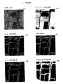
エッジ抽出処理は、画像内の矩形を抽出する前段階として、矩形を形作るエッジ成分のみを取り出す処理である。エッジは少なすぎると矩形の周囲が途切れることが多くなり、多すぎるとノイズ分が入って矩形の断定が困難になるため、エッジ抽出を行う際の閾値等には適切な判断が必要となる。この処理は、まず元画像がモノクロであるかどうかを調べ(ステップ401)、モノクロ画像でない場合はモノクロ化を行う(ステップ402)。画像のモノクロ化は、例えば通常のRGBカラー画像の場合、各画素のR,G,B要素にそれぞれ重みをつけて1次変換することによって白黒の輝度を算出する。モノクロ化画像の一例を図11の符号1101で示す。
【0015】
次に、画像のヒストグラム均等化を行う(ステップ403)。画像のヒストグラム均等化とは、全体的に変化の少ない画像からもエッジが検出できるよう、画像全体または適当な区画ごとに画素値の分布を調べ、その平均値が中間値になるように、1次変換を行うフィルタ処理である。ヒストグラム均等化画像の一例を図11の符号1102で示す。
【0016】
次に、エッジ抽出技法を適用する(ステップ404)。エッジ抽出技法としては、Canny法(J.Canny、 A Computational Approach to Edge Detection、IEEE Transactions on Pattern Analysis and Machine Intelligence.、Vol.PAMI-8、No6、1986年11月 )や、ソーベルフィルタ(尾上守、画像処理ハンドブック、1987年昭晃堂出版)を用いたフィルタ処理などが挙げられる。
このエッジ抽出技法適用画像の一例でCanny法を用いて抽出したエッジ画像の一例を図11に符号1103で示す。
【0017】
次に、画像の2値化を行う(ステップ405)。画像の2値化は、各画素の輝度値と閾値の大小関係を調べ、閾値より大きい画素は最大値に、小さい画素は最小値に置き換えるフィルタ処理である。これにより、各画素はエッジを表す画素と、そうでない画素に2分される。閾値は予め決定されているか、画像またはその一部分の統計情報から決定する。2値化画像の一例を図11に符号1104で示す。
次に、小エッジの除去処理を行う(ステップ406)。この小エッジの除去処理の詳細は図5で後述する。小エッジ除去処理後画像の一例を図11の符号1105で示す。
【0018】
次に、エッジの膨張処理を行う(ステップ407)。エッジの膨張処理は、モルフォロジー(間瀬茂他、モルフォロジーと画像解析[I]、電子情報通信学会誌Vol.74、No2、pp164-174、1991年2月)等の技法を用いて行う。膨張処理後画像の一例を図11の符号1106で示す。この一連の処理で出来た画像をエッジ画像データ112として記憶装置110に格納し、終了する。
【0019】
図5は、図4における小エッジの除去処理(ステップ404)の詳細を示すフローチャートである。
小エッジの除去処理は、エッジ画像内のノイズ除去のために行われる。ただし、矩形を形作る線分の一部を誤って消さないよう、小エッジであっても直線成分の強いものは消さずに残しておく。この処理は、まず2値化を行った画像のエッジを表す画素全てに対して、その画素に連結する画素の数を調べる(ステップ501)。その後、連結する画素の数が一定量以下の画素で作られる線分をリストLに登録する(ステップ502)。この処理の閾値を変化させることで、除去するエッジの量を調節することが出来る。
【0020】
次に、リストLの中に登録されている線分が残っているかどうかを調べ(ステップ503)、残ってない場合は終了する。残っている場合は、その中から1線分を選択し(ステップ504)、その線分の直線性を評価し、その評価をsに代入する(ステップ505)。直線性の評価は、テンプレートマッチング(岸野文郎他著、画像と空間の情報処理、2000年岩波書店出版)等の技法を用いて行う。
次に、sが閾値以下かどうかのチェックを行い(ステップ506)、閾値以下の場合は、その線分を画像から削除する(ステップ507)。
次に、選択した線分をリストLから削除し(ステップ508)、ステップ503のチェックに戻る。
【0021】
図6は、図3の矩形抽出処理(ステップ303)の詳細を示すフローチャートである。
矩形抽出処理は、エッジ抽出された画像から、自動的に出来る部分の矩形抽出を行う処理である。本実施形態では、矩形抽出の正確さを高めるために、処理を2段階(1次抽出と2次抽出)で行っている。この処理は、まず、処理する画像内に任意のシード点を複数決定し、そのリストを作成する(ステップ601)。シード点とは、矩形抽出を行う際の処理の出発点となる座標の事を指す。ここでのシード点の決め方は、格子状に点在させたり、ランダムに配置させたりする方法で行う。次に、ステップ601で作成したシード点のリストを使って処理A、すなわち図6の破線内で囲むステップ605〜609の処理を行い、1次矩形データを作成する(ステップ602)。
【0022】
次に、ステップ602で作成した矩形データを利用し、各矩形の重心を取る等の方法で、各矩形領域の中心位置(または中心近傍)に位置する新しいシード点リストを作成する(ステップ603)。そして、ステップ603で作成したシード点のリストを使って再び処理A、すなわちステップ605〜609の処理を行い、2次矩形データを作成する。
【0023】
処理Aでは、シード点リストに従い、1シード点に対して1矩形を抽出する。以下にその詳しい処理を説明する。
この処理では、まず、リスト内の全てのシード点に対してステップ606〜609のチェックを行ったかどうかを調べ(ステップ605)、全てのチェックが終わっていた場合は終了する。そうでない場合、リストの中からチェックを行っていないシード点を1点選択し(ステップ606)、選択したシード点がそれまでに抽出した矩形の内部に含まれているかどうかのチェックを行う(ステップ607)。どこかの矩形内部に含まれている場合、そのシード点のチェックを終了し、ステップ606の処理に戻る。
どの矩形にも含まれていない場合、本発明の特徴である直線交点法による矩形の抽出を行う(ステップ608)。直線交点法の詳細は、図7に示す。
【0024】
次に、得られた矩形を示す矩形データを登録し(ステップ609)、ステップ605のチェックに戻る。
この処理は、ステップ601及び602の処理のみを行って得られた矩形データをそのまま使うことで簡略化することも可能であるが、その場合、シード点リスト作成のランダム性のため、特にシード点が矩形の端にある場合、正確な矩形データが得られない場合がある。その正確でない矩形の画像例を図13に示す。図13の例では、ランダムに配置されたシード点1301を基にステップ602の矩形領域の抽出処理を行うと、得られる1次矩形データで示される矩形領域は符号1302のようなものになる。
【0025】
そこで、ステップ603〜604の処理を行い、1次矩形データの重心(または中心や中心近傍)を新たなシード点1303に選定し、このシード点1303から放射状に直線1304を伸ばし、エッジとの交点を求め、それらの交点を連結することによって2次矩形データを取り直すことにより、符号1305のようにより正確な矩形領域のデータを抽出することが出来る。
【0026】
図7は、図6における直線交点法による処理(ステップ608)の詳細を示す説明図である。この処理は、与えられたエッジ画像と、シード点を呼ぶ1点の座標から、シード点を含む矩形を抽出する。
まず、エッジ画像701とシード点702が与えられているとする。
この時、シード点から、等角度間隔に全方位に直線703を伸ばし、それぞれの直線とエッジ画像におけるエッジ画素との交点704−1〜704−8を求める。そして、そこで得られた交点704−1〜704−8を結ぶことにより、画像内の矩形領域705を抽出する。
【0027】
矩形データはその矩形領域705を形作る頂点リストから成り立っており、その頂点の数は放射状に伸ばす直線の数による。この直線数を増やすことにより、より精密な矩形の抽出を行うことが出来るが、エッジ画像にノイズ成分がある場合、ノイズ成分との交点を検出してしまう恐れもあるため、画像の種類や目的によって、適度な数を設定しておく必要がある。
【0028】
図8は、図3の調整処理(ステップ305)の詳細を示すフローチャートである。調整処理は、それまでの処理で得られた矩形データをチェックし、不自然な矩形データを検出または除去するために行われる。矩形データのチェックは、主に大きさのチェックと形状のチェックによって行われる。この処理は、まず、この処理の前に行われた矩形抽出処理(ステップ303)で作られた矩形データRMを読み込む(ステップ801)。
【0029】
次に、読み込んだ矩形データRMに登録されている全ての矩形情報を調べたかどうかをチェックし(ステップ802)、全てチェックし終わっている場合、ステップ811の処理へ進む。まだチェックしていない矩形情報がある場合、まだチェックしていない矩形情報を1つ選び(ステップ803)、その矩形の面積を算出して変数sに代入する(ステップ804)。そして、矩形の面積sが予め設定しておいた閾値以下かどうかをチェックし(ステップ805)、閾値以下であった場合は選択した当該矩形情報を削除する(ステップ806)。ここでの面積チェックの閾値は、目的や画像の解像度によって決定される。
【0030】
次に、鋭端矩形の修正を行う(ステップ807)。鋭端矩形の修正とは、矩形の形状のチェックの1つであり、矩形のなかに極端な鋭角で構成される部分を修正する処理である。詳細な処理は図9に示す。
次に、矩形の形状の評価を行い、その評価値を変数Eに代入する(ステップ808)。矩形の形状評価は、ノイズ等による矩形抽出のぶれを少なくするために行う処理で、凹型矩形であったり、極端に細長い形など、土地矩形として不自然な形であるかどうかを、パターン認識(河田 聡他、 科学計測のための画像データ処理、1994年CQ出版社出版)等の手法を用いて評価する。
【0031】
次に、この評価値Eが閾値以上であるかどうかをチェックし(ステップ809)、閾値以上である場合、その矩形を警告矩形リストALに登録し(ステップ810)、ステップ802の処理へ戻る。なお、ステップ809の閾値は、どの程度厳密に形状をチェックするかに関し、画像や目的によって変化する。
【0032】
次に、ステップ802のチェックで全ての矩形情報に対するチェックが終わっている場合、警告矩形リストALに矩形が登録されているかどうかを調べ(ステップ811)、登録されている場合、その矩形を表示装置102の画面に表示する(ステップ812)。
次にユーザによる修正処理を受付け(ステップ813)、処理を終了する。ユーザによる修正処理の詳細は図10に示す。
【0033】
図9は、図8の鋭端矩形の修正処理(ステップ807)の詳細を示すフローチャートである。鋭端矩形の修正処理は、エッジ画像に含まれるノイズやエッジの不完全さに拠る検出矩形の不自然さを修正するための処理である。
例えば、直線交点法による交点がノイズのために1点だけ極端に離れたところにあった場合等に有効である。この処理で修正される矩形データの画像例を図12に示している。この処理は、まず修正を行う矩形情報rを読み込み(ステップ901)、修正を行ったかどうかを示すフラグ変数flagに「0」を代入する(ステップ902)。
【0034】
次に矩形情報rに登録された頂点を全てチェックしたかどうかを調べ(ステップ903)、全て調べた場合はステップ909の処理へ進む。調べてない頂点がある場合、調べてない頂点から1つを選び(ステップ904)、選択した頂点に繋がる2辺の成す角度を調べる(ステップ905)。
次に、その角度が予め設定した閾値以下であるかどうかを調べる(ステップ906)。このときの閾値は、どの程度鋭角でも矩形として自然とみなすかどうかに関わり、目的や画像によって決まる。角度が閾値以下であった場合、その頂点を削除して矩形データを作り直し(ステップ907)、flagに「1」を代入する(ステップ908)。そして、どちらの場合もステップ903の処理に戻る。
【0035】
ステップ903で全ての頂点をチェックしていた場合、変数flagが「1」であるかどうかチェックし(ステップ909)、「1」であった場合はflagに「0」を代入し(ステップ910)、ステップ903の処理に戻る。「1」ではなかった場合には、この処理を終了する。
図12に示す例では、1201のような元のエッジ画像に対して直線交点法による矩形抽出を行った場合に、1202のように一部に極端な鋭端部分1203が存在する矩形を認識している。この場合、土地区画としては不自然な形状のため、鋭端矩形の修正処理において、鋭端部分が閾値以下と判定され、ステップ907の処理で該当する頂点を削除し、1204のように矩形を修正する。
【0036】
図10は、図8のユーザによる修正処理(ステップ813)の詳細を示すブロック図である。ユーザによる修正処理は図8における警告表示(ステップ812)によって不自然な矩形を表示した後、ユーザの入力にしたがって行われる。
ユーザは矩形情報および不自然な形状であるとして警告された矩形の確認し、メニューからコマンドを入力する。
【0037】
コマンドは、図10に示すように、矩形分割1001、矩形合併1002、新矩形抽出1003、シード点取り直し1004、矩形除去1005、終了1006から選ぶことが出来る。
矩形分割1001を選んだ場合、ユーザはさらに分割する矩形と分割線の始点および終点を入力する。これによって、装置は入力情報にしたがって矩形データを変更する。
矩形合併1002を選んだ場合、ユーザはさらに合併する2つの隣接した矩形を選択する。装置はその入力情報にしたがって矩形データを変更する。
新矩形抽出1003を選んだ場合、ユーザはさらに新しいシード点を入力し、その点を使い直線交点法(図7参照)により新しい矩形を抽出し、矩形データに登録する。
シード点取り直し1004を選んだ場合、ユーザはさらに1点を入力する。d装置はその点を含む矩形を、改めて直線交点法を用いて抽出した矩形に置き換える。
矩形除去1005を選んだ場合、ユーザはさらに1矩形を選択する。装置はその矩形情報をデータから削除する。
最後に終了1006選択し、この処理を終了する。
【0038】
図11は、エッジ抽出処理における各処理後の画像のサンプル例である。各画像は、エッジ抽出処理間に得られる画像である。対応は図4の説明に上述した通りである。
図12は、鋭端矩形処理における対象画像のサンプル例である。各画像は、鋭端矩形処理を視覚的に説明している。対応は図9で説明した通りである。
図13は、矩形抽出処理における矩形データの変化のサンプル例である。各画像は、矩形抽出処理の流れを視覚的に説明している。対応は図6で説明した通りである。
【0039】
以上のように本実施形態においては、地表を撮影した画像上の任意の1点から放射状に伸ばした直線とエッジの交点を求め、それを連結することによって画像上の矩形領域を抽出する処理(直線交点法)を自動的に行い、農地等の土地区画の矩形抽出を行う。
この方法によれば、画像上の1点の座標を指定すると、その点から所定角度間隔に全方位に直線を伸ばし、それぞれの直線とエッジ画像におけるエッジ画素との交点を求めて画像内の矩形を抽出することが出来る。シード点の取り方を自動的なものに決定していれば、画像内の全ての矩形の認識を自動的に行うことが出来る。また、処理もエッジトレースに比べて単純なため、短い時間で処理を行うことが出来る。
さらに、直線交点法によって認識した矩形に対し、大きさや形の面で農地区画としてふさわしくないと思われるものをチェックし、ユーザに知らせた後、ユーザの判断を取り入れる調整処理ステップを導入することで、ユーザの負担を最小限にし、認識率を向上させることが可能になる。
【0040】
【発明の効果】
以上のように本発明によれば、農地等の土地区画のデータを高速にかつ、ユーザの負担を最小限にして行うことができる。
【図面の簡単な説明】
【図1】本発明を適用した土地区画データ作成装置の一実施形態を示すブロック構成図である。
【図2】矩形データの構成例を示すデータ構造図である。
【図3】全体的な処理を示すフローチャートである。
【図4】エッジ抽出処理の詳細を示すフローチャートである。
【図5】小エッジ除去処理の詳細を示すフローチャートである。
【図6】矩形抽出処理の詳細を示すフローチャートである。
【図7】直線交点法による矩形抽出処理の説明図である。
【図8】調整処理の詳細を示すフローチャートである。
【図9】鋭端矩形の修正処理の詳細を示すフローチャートである。
【図10】ユーザによる修正処理の詳細を示すブロック図である。
【図11】実施形態におけるエッジ抽出処理過程で得られる画像の変化を示す画像一覧図である。
【図12】実施形態における鋭端矩形の修正処理過程での画像の変化を示す画像一覧図である。
【図13】実施形態における矩形抽出処理過程での画像の変化を示す画像一覧図である。
【符号の説明】
101…入力装置、102…表示装置、103…出力装置、105…処理装置、106…プログラム、107…エッジ抽出処理部、108…矩形情報抽出処理部、109…調整処理部。[0001]
BACKGROUND OF THE INVENTION
The present invention relates to a method and apparatus for analyzing observation images obtained by photographing a ground surface from an altitude using a satellite, an aircraft, and the like, and creating data relating to land sections on the ground surface.
[0002]
[Prior art]
In recent years, the use of satellite photographs and aerial photographs has become widespread, and techniques related to the creation of maps using these images and the analysis of the ground surface have been developed. Among them, a method for recognizing a farm district image in an image is indispensable for analyzing a photograph taken of a farmland part.
The recognition of the farm district image is performed by extracting a polygon (hereinafter referred to as a rectangle) surrounded by an edge representing the farmland from the image. As an existing technique for recognizing a rectangle in an image, a method for performing edge tracing from an image obtained by extracting and binarizing an edge has already been disclosed in Japanese Patent Application Laid-Open No. 11-266373 “Image Processing Device”.
Japanese Patent Application No. 6-146651, “Intra-frame region rectangularization device” discloses a method of specifying an area with a marker pen or the like and then reading it as rectangular information.
[0003]
[Problems to be solved by the invention]
In the edge trace of the rectangular region recognition method according to the conventional technique described above, the user needs to judge the trace direction during the process, and the process inevitably becomes an interactive process. There is a problem that the labor burden is large. In addition, the method for recognizing a designated area using a marker pen or the like has a problem that the user has to mark all the areas to be recognized in advance, which also imposes a heavy labor burden on the user.
[0004]
An object of the present invention is to provide a land parcel data creation method and apparatus that can reduce the burden on the user and can create land parcel data such as farmland at high speed.
[0005]
[Means for Solving the Problems]
In order to achieve the above object, the land parcel data creation method according to the present invention is a method for creating land parcel data by analyzing observation images obtained by photographing the ground surface from altitude flying objects such as satellites and aircraft with a processing device. And
An edge extraction processing step of reading the observation image stored in the storage device and extracting an edge of the observation image;
A primary extraction process for obtaining an intersection of a plurality of straight lines and edges extending radially from an arbitrary point on the image and extracting a rectangular region on the image by connecting the intersections to the extracted image. Step, obtain a center position in the extracted rectangular area, obtain intersections of a plurality of straight lines and edges radially extending from the center position, and extract the rectangular area on the image by connecting these intersections 2 A rectangular area extraction processing step comprising a next extraction processing step;
And an adjustment processing step for selecting and correcting the extracted rectangular area.
Further, the adjustment processing step checks the angle at each vertex of the extracted rectangular area, and for a rectangular area including an acute angle equal to or less than a predetermined threshold, the acute angle vertex is deleted to shape the shape of the rectangular area. Including processing.
Further, the adjustment processing step includes a process of collating the shape of the extracted rectangular area with a preset land rectangular pattern and deleting data of the unnatural rectangular area as the land shape.
Further, the adjustment processing step includes a process of displaying a rectangular area that is difficult to determine whether it is a land parcel, and deleting or correcting the rectangular area in accordance with a designation from a user.
[0006]
The land parcel data creating apparatus according to the present invention is an apparatus for analyzing land images from an altitude flying object such as a satellite or an aircraft, and creating land parcel data,
Edge extraction processing means for reading out the observed image stored in the storage device and extracting an edge of the observed image;
A primary extraction process for obtaining an intersection of a plurality of straight lines and edges extending radially from an arbitrary point on the image and extracting a rectangular region on the image by connecting the intersections to the extracted image. Means and a central position in the extracted rectangular area are obtained, intersections between a plurality of straight lines and edges extending radially from the central position are obtained, and a rectangular area on the image is extracted by connecting the intersections 2 A rectangular area extraction processing means comprising a next extraction processing means;
And adjustment processing means for selecting and correcting the extracted rectangular area.
Further, the adjustment processing unit checks the angle at each vertex of the extracted rectangular area, and for a rectangular area including an acute angle equal to or less than a predetermined threshold, the acute angle vertex is deleted to shape the shape of the rectangular area. Processing means is included.
Further, the adjustment processing means includes processing means for collating the shape of the extracted rectangular area with a preset land rectangular pattern and deleting data of the unnatural rectangular area as the land shape.
Further, the adjustment processing means includes processing means for displaying a rectangular area that is difficult to determine whether it is a land parcel, and deleting or correcting the rectangular area in accordance with a designation from the user.
[0007]
DETAILED DESCRIPTION OF THE INVENTION
Hereinafter, an embodiment of the present invention will be described with reference to the drawings.
In this embodiment, the observation image information obtained by photographing the ground surface from an altitude flying object such as a satellite or an aircraft is used as an input, and automatic processing recognizes land sections such as farmland and displays warnings of unnatural parts, according to user input. After performing the fine adjustment process, the rectangle information of the final land parcel is output.
FIG. 1 is a block configuration diagram showing an embodiment of a land parcel data creation apparatus to which the present invention is applied.
The apparatus of this embodiment includes an
The
The
[0008]
The apparatus according to the present embodiment receives observation image data obtained by photographing the ground surface from an altitude flying object such as a satellite or an aircraft, and executes a series of
[0009]
FIG. 2 is a data structure diagram showing an example of the
The rectangle management information is composed of statistical information that summarizes the rectangle information and each piece of rectangle information. Specifically, an ID (201) for uniquely identifying the rectangle management information, an original image ID (202) for uniquely identifying an image before processing, and a corresponding rectangle image information for uniquely identifying Rectangle image ID (203), the number of rectangles registered in the rectangle management information (204), the average area of all registered rectangles (205), the registered rectangle information (206), (207), etc. Is done.
[0010]
The rectangle information is composed of detailed information of each rectangle. Specifically, an ID (211) for uniquely identifying the rectangle information, an area (212) of the rectangle, a center coordinate (213) of the rectangle, and a feature quantity (214 such as average luminance in the rectangle of the original image) ), The number of vertices forming a rectangle (215), the coordinates of each vertex (216), (217), and the like.
[0011]
The rectangular image information is data shown in the same format as normal image information, and can be used for simple display and reverse lookup from coordinates to rectangular data. Specifically, as shown in FIG. 2 (c), in the form of a monochrome image, values for identifying pixels outside the rectangle (00), boundary line pixels (FF), and pixels within the rectangle are stored in the data of each pixel. To do. In particular, when one pixel belongs to only one piece of rectangular information, correspondence with the rectangular information is obtained by using the rectangular information IDn (corresponding to 211 in FIG. 2B) as the pixel value within the rectangle.
[0012]
FIG. 3 is a flowchart showing an outline of the
First, observed image data is read (step 301) and stored as
Next, edge extraction processing is performed from the original image data 111 (step 302), and the obtained edge image data (112) is stored in the
[0013]
Next, an automatic rectangle extraction process is performed (step 303), and the obtained
Next, it is determined whether or not the adjustment process is completed (step 304). This determination is performed by a method according to the purpose, such as automatic determination, limit definition by the number of times, or determination by user input. In the case of termination, the final
[0014]
FIG. 4 is a flowchart showing details of the edge extraction process (step 302) of FIG.
The edge extraction process is a process for extracting only edge components that form a rectangle as a previous stage of extracting the rectangle in the image. If the number of edges is too small, the periphery of the rectangle is often interrupted. If the number is too large, noise is included and it is difficult to determine the rectangle. Therefore, it is necessary to appropriately determine the threshold when performing edge extraction. In this process, first, it is checked whether or not the original image is monochrome (step 401), and if it is not a monochrome image, monochrome conversion is performed (step 402). For example, in the case of a normal RGB color image, the monochrome of an image is calculated by weighting the R, G, and B elements of each pixel and performing primary conversion. An example of the monochrome image is denoted by
[0015]
Next, image equalization is performed (step 403). The histogram equalization of the image means that the distribution of pixel values is examined for the entire image or for each appropriate section so that the edge can be detected even from an image with little change as a whole, and the average value becomes an intermediate value. This is a filter process for performing the next conversion. An example of the histogram equalized image is indicated by
[0016]
Next, an edge extraction technique is applied (step 404). Edge extraction techniques include the Canny method (J. Canny, A Computational Approach to Edge Detection, IEEE Transactions on Pattern Analysis and Machine Intelligence., Vol. PAMI-8, No6, November 1986) and the Sobel filter (Onoe). Filter processing using Mamoru, Image Processing Handbook, 1987 Shoshodo Publishing).
An example of an edge image extracted by using the Canny method in an example of this edge extraction technique applied image is indicated by
[0017]
Next, the image is binarized (step 405). The binarization of the image is a filtering process in which the relationship between the luminance value of each pixel and the threshold value is examined, and pixels larger than the threshold value are replaced with the maximum value and small pixels are replaced with the minimum value. As a result, each pixel is divided into a pixel representing an edge and a pixel not representing that edge. The threshold value is determined in advance or determined from statistical information of the image or a part thereof. An example of the binarized image is denoted by
Next, small edge removal processing is performed (step 406). Details of the small edge removal processing will be described later with reference to FIG. An example of the image after the small edge removal process is denoted by
[0018]
Next, edge expansion processing is performed (step 407). Edge expansion processing is performed using techniques such as morphology (Shigeru Mase et al., Morphology and image analysis [I], Journal of the Institute of Electronics, Information and Communication Engineers, Vol. 74, No. 2, pp164-174, February 1991). An example of the image after expansion processing is indicated by
[0019]
FIG. 5 is a flowchart showing details of the small edge removal process (step 404) in FIG.
The small edge removal process is performed to remove noise in the edge image. However, in order not to erase part of the line segment forming the rectangle by mistake, even a small edge is left without being erased. In this process, first, for all pixels representing the edge of the binarized image, the number of pixels connected to the pixel is examined (step 501). Thereafter, a line segment made up of pixels having a certain number of connected pixels or less is registered in the list L (step 502). By changing the threshold value of this process, the amount of edge to be removed can be adjusted.
[0020]
Next, it is checked whether or not a line segment registered in the list L remains (step 503). If the line remains, one line segment is selected (step 504), the linearity of the line segment is evaluated, and the evaluation is substituted for s (step 505). Linearity is evaluated using techniques such as template matching (Fumiro Kishino et al., Information processing of images and space, 2000 published by Iwanami Shoten).
Next, it is checked whether or not s is equal to or less than a threshold value (step 506). If it is equal to or less than the threshold value, the line segment is deleted from the image (step 507).
Next, the selected line segment is deleted from the list L (step 508), and the process returns to the check in
[0021]
FIG. 6 is a flowchart showing details of the rectangle extraction process (step 303) of FIG.
The rectangle extraction process is a process of automatically extracting a portion of a rectangle that can be automatically performed from an edge extracted image. In the present embodiment, processing is performed in two stages (primary extraction and secondary extraction) in order to increase the accuracy of rectangle extraction. In this process, first, a plurality of arbitrary seed points are determined in the image to be processed, and a list thereof is created (step 601). The seed point refers to a coordinate that is a starting point of processing when performing rectangular extraction. Here, the seed points are determined by a method in which the seed points are scattered in a lattice pattern or randomly arranged. Next, using the list of seed points created in
[0022]
Next, a new seed point list located at the center position (or near the center) of each rectangular area is created by using the rectangular data created in
[0023]
In the process A, one rectangle is extracted for one seed point according to the seed point list. The detailed process will be described below.
In this process, first, it is checked whether or not all the seed points in the list have been checked in
If none of the rectangles is included, a rectangle is extracted by the linear intersection method, which is a feature of the present invention (step 608). Details of the linear intersection method are shown in FIG.
[0024]
Next, rectangle data indicating the obtained rectangle is registered (step 609), and the process returns to the check in
This processing can be simplified by using the rectangular data obtained by performing only the processing in
[0025]
Accordingly, the processes of
[0026]
FIG. 7 is an explanatory diagram showing details of the process (step 608) by the linear intersection method in FIG. In this process, a rectangle including the seed point is extracted from the given edge image and the coordinates of one point that calls the seed point.
First, it is assumed that an
At this time,
[0027]
The rectangular data is composed of a vertex list forming the
[0028]
FIG. 8 is a flowchart showing details of the adjustment process (step 305) of FIG. The adjustment process is performed to check the rectangular data obtained in the process so far and detect or remove unnatural rectangular data. The rectangular data is checked mainly by checking the size and checking the shape. In this process, first, the rectangular data RM created in the rectangular extraction process (step 303) performed before this process is read (step 801).
[0029]
Next, it is checked whether or not all rectangular information registered in the read rectangular data RM has been checked (step 802). If all the rectangular information has been checked, the process proceeds to step 811. If there is rectangular information that has not been checked yet, one piece of rectangular information that has not been checked is selected (step 803), and the area of the rectangle is calculated and substituted into the variable s (step 804). Then, it is checked whether or not the rectangular area s is equal to or smaller than a preset threshold value (step 805). If the rectangular area s is equal to or smaller than the threshold value, the selected rectangular information is deleted (step 806). The area check threshold here is determined by the purpose and the resolution of the image.
[0030]
Next, the sharp end rectangle is corrected (step 807). The sharp end rectangle correction is one of the checks of the shape of the rectangle, and is a process of correcting a portion constituted by an extreme acute angle in the rectangle. Detailed processing is shown in FIG.
Next, the rectangular shape is evaluated, and the evaluation value is substituted into the variable E (step 808). Rectangle shape evaluation is a process performed to reduce the blurring of rectangle extraction due to noise, etc., and pattern recognition (whether it is a concave rectangle or an extremely elongated shape such as an unnatural shape as a land rectangle) Evaluation is made using methods such as Satoshi Kawada et al., Image data processing for scientific measurement, 1994 published by CQ Publishing).
[0031]
Next, it is checked whether or not the evaluation value E is equal to or greater than a threshold value (step 809). If the evaluation value E is equal to or greater than the threshold value, the rectangle is registered in the warning rectangle list AL (step 810), and the process returns to step 802. Note that the threshold value in
[0032]
Next, when all the pieces of rectangle information have been checked in the check in
Next, the correction process by the user is accepted (step 813), and the process ends. Details of the correction processing by the user are shown in FIG.
[0033]
FIG. 9 is a flowchart showing details of the sharp edge rectangle correction processing (step 807) of FIG. The sharp rectangle correction process is a process for correcting the unnaturalness of the detected rectangle due to the noise included in the edge image or the imperfection of the edge.
For example, this is effective when the intersection by the linear intersection method is extremely far away by one point due to noise. An example of the rectangular data image corrected by this processing is shown in FIG. In this process, first, rectangular information r to be corrected is read (step 901), and “0” is substituted into a flag variable flag indicating whether the correction has been performed (step 902).
[0034]
Next, it is checked whether or not all the vertices registered in the rectangle information r have been checked (step 903). If all the vertices have been checked, the process proceeds to step 909. If there is an unexamined vertex, one is selected from the unexamined vertices (step 904), and the angle formed by the two sides connected to the selected vertex is examined (step 905).
Next, it is checked whether or not the angle is equal to or smaller than a preset threshold value (step 906). The threshold value at this time is related to whether or not an acute angle is regarded as a natural rectangle, and depends on the purpose and the image. If the angle is equal to or smaller than the threshold value, the vertex is deleted to recreate rectangular data (step 907), and “1” is substituted for flag (step 908). In either case, the process returns to step 903.
[0035]
If all the vertices are checked in
In the example shown in FIG. 12, when a rectangle extraction is performed on the original edge image such as 1201 by the linear intersection method, a rectangle having an extreme
[0036]
FIG. 10 is a block diagram showing details of the correction process (step 813) by the user in FIG. The correction process by the user is performed according to the user input after displaying an unnatural rectangle by the warning display (step 812) in FIG.
The user confirms the rectangle information and the rectangle warned as an unnatural shape, and inputs a command from the menu.
[0037]
As shown in FIG. 10, the command can be selected from
When the
If the
When the
When the
When the
Finally, the
[0038]
FIG. 11 is an example of an image sample after each process in the edge extraction process. Each image is an image obtained during the edge extraction process. The correspondence is as described above in the description of FIG.
FIG. 12 is an example of a target image sample in the sharp end rectangle processing. Each image visually describes sharp edge rectangle processing. The correspondence is as described in FIG.
FIG. 13 is a sample example of changes in rectangular data in the rectangular extraction process. Each image visually describes the flow of the rectangular extraction process. The correspondence is as described in FIG.
[0039]
As described above, in the present embodiment, a process of extracting a rectangular region on an image by obtaining an intersection of a straight line and an edge extending radially from an arbitrary point on the image obtained by photographing the ground surface and connecting them ( (Linear intersection method) is automatically performed to extract a rectangle of land parcels such as farmland.
According to this method, when the coordinates of one point on the image are specified, a straight line is extended in all directions from that point at a predetermined angular interval, and the intersection of each straight line and the edge pixel in the edge image is obtained. Can be extracted. If the seed point is automatically determined, all rectangles in the image can be automatically recognized. In addition, since processing is simpler than edge tracing, processing can be performed in a short time.
In addition, by checking the rectangle recognized by the linear intersection method that is not suitable as an agricultural district image in terms of size and shape, informing the user, and then introducing an adjustment processing step that incorporates the user's judgment The burden on the user can be minimized and the recognition rate can be improved.
[0040]
【The invention's effect】
As described above, according to the present invention, it is possible to perform data on land parcels such as farmland at high speed while minimizing the burden on the user.
[Brief description of the drawings]
FIG. 1 is a block configuration diagram showing an embodiment of a land parcel data creation apparatus to which the present invention is applied.
FIG. 2 is a data structure diagram illustrating a configuration example of rectangular data.
FIG. 3 is a flowchart showing overall processing.
FIG. 4 is a flowchart showing details of edge extraction processing;
FIG. 5 is a flowchart showing details of a small edge removal process.
FIG. 6 is a flowchart showing details of rectangle extraction processing.
FIG. 7 is an explanatory diagram of rectangle extraction processing by a linear intersection method.
FIG. 8 is a flowchart showing details of adjustment processing.
FIG. 9 is a flowchart showing details of a sharp edge rectangle correction process;
FIG. 10 is a block diagram showing details of correction processing by a user.
FIG. 11 is an image list diagram showing changes in images obtained in the edge extraction process in the embodiment.
FIG. 12 is a list of images showing image changes in the process of correcting a sharp rectangle in the embodiment.
FIG. 13 is an image list diagram showing image changes during the rectangular extraction process in the embodiment;
[Explanation of symbols]
DESCRIPTION OF
Claims (8)
記憶装置に格納された前記観測画像を読出し、該観測画像のエッジを抽出するエッジ抽出処理ステップと、
抽出した画像に対して、画像上の任意の1点から放射状に伸ばした複数の直線とエッジとの交点を求め、それらの交点を連結することによって画像上の矩形領域を抽出する1次抽出処理ステップと、抽出した矩形領域内の中心位置を求め、その中心位置から放射状に伸ばした複数の直線とエッジとの交点を求め、それらの交点を連結することによって画像上の矩形領域を抽出する2次抽出処理ステップとか成る矩形領域抽出処理ステップと、
抽出された矩形領域の選別および修正を行う調整処理ステップとを含むことを特徴とする土地区画データ作成方法。It is a method of creating land parcel data by analyzing observation images taken from the altitude flying object such as satellites and aircraft with a processing device,
An edge extraction processing step of reading the observation image stored in the storage device and extracting an edge of the observation image;
A primary extraction process for obtaining an intersection of a plurality of straight lines and edges extending radially from an arbitrary point on the image and extracting a rectangular region on the image by connecting the intersections to the extracted image. Step, obtain a center position in the extracted rectangular area, obtain intersections of a plurality of straight lines and edges radially extending from the center position, and extract the rectangular area on the image by connecting these intersections 2 A rectangular area extraction processing step comprising a next extraction processing step;
A land parcel data creation method comprising: an adjustment processing step for selecting and correcting the extracted rectangular area.
記憶装置に格納された前記観測画像を読出し、該観測画像のエッジを抽出するエッジ抽出処理手段と、
抽出した画像に対して、画像上の任意の1点から放射状に伸ばした複数の直線とエッジとの交点を求め、それらの交点を連結することによって画像上の矩形領域を抽出する1次抽出処理手段と、抽出した矩形領域内の中心位置を求め、その中心位置から放射状に伸ばした複数の直線とエッジとの交点を求め、それらの交点を連結することによって画像上の矩形領域を抽出する2次抽出処理手段とか成る矩形領域抽出処理手段と、
抽出された矩形領域の選別および修正を行う調整処理手段とを備えることを特徴とする土地区画データ作成装置。A device that creates land parcel data by analyzing observation images taken from the surface of an altitude projectile such as a satellite or aircraft.
Edge extraction processing means for reading out the observed image stored in the storage device and extracting an edge of the observed image;
A primary extraction process for obtaining an intersection of a plurality of straight lines and edges extending radially from an arbitrary point on the image and extracting a rectangular region on the image by connecting the intersections to the extracted image. Means and a central position in the extracted rectangular area are obtained, intersections between a plurality of straight lines and edges extending radially from the central position are obtained, and a rectangular area on the image is extracted by connecting the intersections 2 A rectangular area extraction processing means comprising a next extraction processing means;
A land parcel data creation device comprising adjustment processing means for selecting and correcting an extracted rectangular area.
Priority Applications (2)
| Application Number | Priority Date | Filing Date | Title |
|---|---|---|---|
| JP2002055960A JP4172941B2 (en) | 2002-03-01 | 2002-03-01 | Land parcel data creation method and apparatus |
| US10/360,624 US7127107B2 (en) | 2002-03-01 | 2003-02-10 | Land partition data generating method and apparatus |
Applications Claiming Priority (1)
| Application Number | Priority Date | Filing Date | Title |
|---|---|---|---|
| JP2002055960A JP4172941B2 (en) | 2002-03-01 | 2002-03-01 | Land parcel data creation method and apparatus |
Publications (3)
| Publication Number | Publication Date |
|---|---|
| JP2003256807A JP2003256807A (en) | 2003-09-12 |
| JP2003256807A5 JP2003256807A5 (en) | 2005-04-28 |
| JP4172941B2 true JP4172941B2 (en) | 2008-10-29 |
Family
ID=27800067
Family Applications (1)
| Application Number | Title | Priority Date | Filing Date |
|---|---|---|---|
| JP2002055960A Expired - Fee Related JP4172941B2 (en) | 2002-03-01 | 2002-03-01 | Land parcel data creation method and apparatus |
Country Status (2)
| Country | Link |
|---|---|
| US (1) | US7127107B2 (en) |
| JP (1) | JP4172941B2 (en) |
Families Citing this family (36)
| Publication number | Priority date | Publication date | Assignee | Title |
|---|---|---|---|---|
| JP3944024B2 (en) * | 2002-08-20 | 2007-07-11 | 株式会社東芝 | Image processing method, semiconductor device manufacturing method, pattern inspection apparatus, and program |
| GB0427484D0 (en) * | 2004-12-15 | 2005-01-19 | Money Controls Ltd | Acceptor device for sheet objects |
| JP5074622B2 (en) * | 2005-11-01 | 2012-11-14 | 株式会社日立ソリューションズ | Geographic image processing system |
| JP4908867B2 (en) * | 2005-11-01 | 2012-04-04 | 株式会社日立ソリューションズ | Geographic image processing system |
| JP2008003935A (en) * | 2006-06-23 | 2008-01-10 | Ntt Facilities Inc | Data editing method and device, data editing program, and recording medium recording this program |
| JP2008097315A (en) * | 2006-10-12 | 2008-04-24 | Matsushita Electric Works Ltd | Graphic pattern specifying system, graphic pattern collation system using the same, and integration system using the same |
| US7917292B1 (en) | 2006-10-17 | 2011-03-29 | Jpmorgan Chase Bank, N.A. | Systems and methods for flood risk assessment |
| US8655595B1 (en) | 2006-10-17 | 2014-02-18 | Corelogic Solutions, Llc | Systems and methods for quantifying flood risk |
| KR100780242B1 (en) * | 2006-11-14 | 2007-11-27 | 삼성전기주식회사 | Method and apparatus for removing noise in dark area of image |
| US8542884B1 (en) | 2006-11-17 | 2013-09-24 | Corelogic Solutions, Llc | Systems and methods for flood area change detection |
| US8649567B1 (en) | 2006-11-17 | 2014-02-11 | Corelogic Solutions, Llc | Displaying a flood change map with change designators |
| US8077927B1 (en) | 2006-11-17 | 2011-12-13 | Corelogic Real Estate Solutions, Llc | Updating a database with determined change identifiers |
| US8538918B1 (en) | 2006-12-05 | 2013-09-17 | Corelogic Solutions, Llc | Systems and methods for tracking parcel data acquisition |
| JP4928993B2 (en) * | 2007-03-14 | 2012-05-09 | 株式会社日立ソリューションズ | Farm district drawing data creation system |
| US8385672B2 (en) * | 2007-05-01 | 2013-02-26 | Pictometry International Corp. | System for detecting image abnormalities |
| US9262818B2 (en) | 2007-05-01 | 2016-02-16 | Pictometry International Corp. | System for detecting image abnormalities |
| US8638327B2 (en) * | 2007-11-14 | 2014-01-28 | Microsoft Corporation | Tiled projections for planar processing of round earth data |
| US8320615B2 (en) * | 2008-02-27 | 2012-11-27 | Honeywell International Inc. | Systems and methods for recognizing a target from a moving platform |
| US9047515B2 (en) * | 2009-09-13 | 2015-06-02 | Delacom Detection Systems Llc | Method and system for wildfire detection using a visible range camera |
| US8488958B2 (en) | 2010-05-25 | 2013-07-16 | Apple Inc. | Scene adaptive auto exposure |
| US8410977B2 (en) * | 2011-02-17 | 2013-04-02 | Honeywell International Inc. | Methods and systems for identifying hazardous flight zone areas on a display |
| WO2012169294A1 (en) * | 2011-06-09 | 2012-12-13 | 国立大学法人京都大学 | Dtm estimation method, dtm estimation program, dtm estimation device, and method for creating 3-dimensional building model, as well as region extraction method, region extraction program, and region extraction device |
| JP5871571B2 (en) * | 2011-11-11 | 2016-03-01 | 株式会社Pfu | Image processing apparatus, rectangle detection method, and computer program |
| JP5822664B2 (en) | 2011-11-11 | 2015-11-24 | 株式会社Pfu | Image processing apparatus, straight line detection method, and computer program |
| JP5854774B2 (en) | 2011-11-11 | 2016-02-09 | 株式会社Pfu | Image processing apparatus, straight line detection method, and computer program |
| JP5857821B2 (en) * | 2012-03-16 | 2016-02-10 | 富士通株式会社 | Program, partition extraction method, and information processing apparatus |
| AU2013273787A1 (en) * | 2013-12-20 | 2015-07-09 | Canon Kabushiki Kaisha | Method of detecting regions in an edge-based representation |
| CN107148569B (en) * | 2014-09-29 | 2020-01-03 | 株式会社Ihi | Image analysis device, image analysis method, and program |
| US9942440B2 (en) | 2016-07-25 | 2018-04-10 | Clearag, Inc. | Image-based field boundary detection and identification |
| CN108319895B (en) * | 2017-12-29 | 2021-09-17 | 百度在线网络技术(北京)有限公司 | Method and device for identifying intersection in electronic map |
| US11138712B2 (en) * | 2018-07-12 | 2021-10-05 | TerraClear Inc. | Systems and methods to determine object position using images captured from mobile image collection vehicle |
| CN109146889B (en) * | 2018-07-13 | 2021-11-19 | 洛阳中科龙网创新科技有限公司 | Farmland boundary extraction method based on high-resolution remote sensing image |
| US10331966B1 (en) * | 2018-10-19 | 2019-06-25 | Capital One Services, Llc | Image processing to detect a rectangular object |
| US11170230B2 (en) | 2019-02-26 | 2021-11-09 | Tusimple, Inc. | Method and system for map construction |
| US10803635B2 (en) * | 2019-02-26 | 2020-10-13 | Tusimple, Inc. | Method and system for map construction |
| CN113091757B (en) * | 2019-12-23 | 2022-09-27 | 百度在线网络技术(北京)有限公司 | Map generation method and device |
Family Cites Families (13)
| Publication number | Priority date | Publication date | Assignee | Title |
|---|---|---|---|---|
| US5377102A (en) * | 1992-03-05 | 1994-12-27 | Nishiishigaki; Kenji | Apparatus for preparing map data with regional properties |
| EP0686932A3 (en) * | 1994-03-17 | 1997-06-25 | Texas Instruments Inc | A computer vision system to detect 3-D rectangular objects |
| JP3090848B2 (en) | 1994-06-28 | 2000-09-25 | 株式会社東芝 | In-frame area rectangularization device |
| EP1783724A2 (en) * | 1996-06-19 | 2007-05-09 | Matsushita Electric Industrial Co., Ltd. | Road area extracting apparatus for extracting a road area from a block map, deformed map automatic generation system for generating a deformed map from road area data obtained by the road area extracting apparatus, map information providing system, geographical information providing system and geographical information describing method |
| JPH11184375A (en) * | 1997-12-25 | 1999-07-09 | Toyota Motor Corp | Apparatus and method for digital map data processing |
| JP3700381B2 (en) | 1998-03-18 | 2005-09-28 | コニカミノルタビジネステクノロジーズ株式会社 | Image processing device |
| JP3330090B2 (en) * | 1998-09-30 | 2002-09-30 | 松下電器産業株式会社 | Organ boundary extraction method and apparatus |
| US6446060B1 (en) * | 1999-01-26 | 2002-09-03 | International Business Machines Corporation | System and method for sequential processing for content-based retrieval of composite objects |
| JP2000293696A (en) * | 1999-04-07 | 2000-10-20 | Matsushita Electric Ind Co Ltd | Picture recognizing device |
| US6993157B1 (en) * | 1999-05-18 | 2006-01-31 | Sanyo Electric Co., Ltd. | Dynamic image processing method and device and medium |
| US6853751B1 (en) * | 2000-03-31 | 2005-02-08 | Cognex Technology And Investment Corporation | Location of generally rectangular shaped objects in an image |
| JP2002157576A (en) * | 2000-11-22 | 2002-05-31 | Nec Corp | Device and method for processing stereo image and recording medium for recording stereo image processing program |
| JP2003016463A (en) * | 2001-07-05 | 2003-01-17 | Toshiba Corp | Extracting method for outline of figure, method and device for pattern inspection, program, and computer- readable recording medium with the same stored therein |
-
2002
- 2002-03-01 JP JP2002055960A patent/JP4172941B2/en not_active Expired - Fee Related
-
2003
- 2003-02-10 US US10/360,624 patent/US7127107B2/en not_active Expired - Fee Related
Also Published As
| Publication number | Publication date |
|---|---|
| US20030165258A1 (en) | 2003-09-04 |
| JP2003256807A (en) | 2003-09-12 |
| US7127107B2 (en) | 2006-10-24 |
Similar Documents
| Publication | Publication Date | Title |
|---|---|---|
| JP4172941B2 (en) | Land parcel data creation method and apparatus | |
| JP7155321B2 (en) | Crack analysis data editing device, crack analysis data editing method, and crack analysis data editing program | |
| US6404936B1 (en) | Subject image extraction method and apparatus | |
| US6778703B1 (en) | Form recognition using reference areas | |
| CN111986099A (en) | Tillage monitoring method and system based on convolutional neural network with residual error correction fused | |
| US7616828B2 (en) | Geospatial modeling system providing geospatial model data target point filtering based upon radial line segments and related methods | |
| JP4103898B2 (en) | Map information updating method and map updating apparatus | |
| CN110909640A (en) | Method and device for determining water level line, storage medium and electronic device | |
| Grigillo et al. | Automated building extraction from IKONOS images in suburban areas | |
| CN110633620B (en) | Pointer instrument scale identification method and electronic equipment | |
| CN102750538A (en) | Go competition result analysis method based on image processing technique | |
| CN113362331A (en) | Image segmentation method and device, electronic equipment and computer storage medium | |
| CN110298353A (en) | A kind of character identifying method and system | |
| CN110852207A (en) | Blue roof building extraction method based on object-oriented image classification technology | |
| CN113221869A (en) | Medical invoice structured information extraction method, device and equipment and storage medium | |
| JPH05181411A (en) | Map information collation and update system | |
| JP3330829B2 (en) | Automatic detection method of evaluable area in images of machine parts | |
| JPH07210655A (en) | Image processor for ophthalmology | |
| JP4088386B2 (en) | How to update map information | |
| JP2009176163A (en) | Section data creation system | |
| JP3597148B2 (en) | Fingerprint feature extraction device, fingerprint feature extraction method, and fingerprint extraction program | |
| JP2005346665A (en) | Shoreline extraction method and shoreline-extracting system | |
| CN110443811B (en) | Full-automatic segmentation method for complex background leaf image | |
| CN110097062B (en) | Pointer identification method using pointer center point | |
| JP2004094427A (en) | Slip image processor and program for realizing the same device |
Legal Events
| Date | Code | Title | Description |
|---|---|---|---|
| A521 | Request for written amendment filed |
Free format text: JAPANESE INTERMEDIATE CODE: A523 Effective date: 20040616 |
|
| A621 | Written request for application examination |
Free format text: JAPANESE INTERMEDIATE CODE: A621 Effective date: 20040616 |
|
| A977 | Report on retrieval |
Free format text: JAPANESE INTERMEDIATE CODE: A971007 Effective date: 20070726 |
|
| A131 | Notification of reasons for refusal |
Free format text: JAPANESE INTERMEDIATE CODE: A131 Effective date: 20071016 |
|
| A521 | Request for written amendment filed |
Free format text: JAPANESE INTERMEDIATE CODE: A523 Effective date: 20071217 |
|
| A131 | Notification of reasons for refusal |
Free format text: JAPANESE INTERMEDIATE CODE: A131 Effective date: 20080611 |
|
| A521 | Request for written amendment filed |
Free format text: JAPANESE INTERMEDIATE CODE: A523 Effective date: 20080722 |
|
| TRDD | Decision of grant or rejection written | ||
| A01 | Written decision to grant a patent or to grant a registration (utility model) |
Free format text: JAPANESE INTERMEDIATE CODE: A01 Effective date: 20080812 |
|
| A01 | Written decision to grant a patent or to grant a registration (utility model) |
Free format text: JAPANESE INTERMEDIATE CODE: A01 |
|
| A61 | First payment of annual fees (during grant procedure) |
Free format text: JAPANESE INTERMEDIATE CODE: A61 Effective date: 20080812 |
|
| R150 | Certificate of patent or registration of utility model |
Free format text: JAPANESE INTERMEDIATE CODE: R150 |
|
| FPAY | Renewal fee payment (event date is renewal date of database) |
Free format text: PAYMENT UNTIL: 20110822 Year of fee payment: 3 |
|
| FPAY | Renewal fee payment (event date is renewal date of database) |
Free format text: PAYMENT UNTIL: 20110822 Year of fee payment: 3 |
|
| FPAY | Renewal fee payment (event date is renewal date of database) |
Free format text: PAYMENT UNTIL: 20140822 Year of fee payment: 6 |
|
| LAPS | Cancellation because of no payment of annual fees |