JP4170833B2 - Blow molded container for aseptic filling and sterilization method thereof - Google Patents
Blow molded container for aseptic filling and sterilization method thereof Download PDFInfo
- Publication number
- JP4170833B2 JP4170833B2 JP2003176587A JP2003176587A JP4170833B2 JP 4170833 B2 JP4170833 B2 JP 4170833B2 JP 2003176587 A JP2003176587 A JP 2003176587A JP 2003176587 A JP2003176587 A JP 2003176587A JP 4170833 B2 JP4170833 B2 JP 4170833B2
- Authority
- JP
- Japan
- Prior art keywords
- container
- blow
- molded
- aseptic filling
- aseptic
- Prior art date
- Legal status (The legal status is an assumption and is not a legal conclusion. Google has not performed a legal analysis and makes no representation as to the accuracy of the status listed.)
- Expired - Lifetime
Links
- 238000012371 Aseptic Filling Methods 0.000 title claims description 79
- 230000001954 sterilising effect Effects 0.000 title claims description 61
- 238000004659 sterilization and disinfection Methods 0.000 title claims description 47
- 238000000034 method Methods 0.000 title claims description 34
- 238000000071 blow moulding Methods 0.000 claims description 24
- 238000011049 filling Methods 0.000 claims description 14
- 230000004888 barrier function Effects 0.000 claims description 10
- 238000004806 packaging method and process Methods 0.000 claims description 4
- 230000002093 peripheral effect Effects 0.000 claims description 4
- 238000004140 cleaning Methods 0.000 description 9
- 230000000694 effects Effects 0.000 description 9
- 230000032258 transport Effects 0.000 description 9
- -1 for example Substances 0.000 description 8
- 239000007789 gas Substances 0.000 description 8
- 238000001035 drying Methods 0.000 description 7
- 229920005989 resin Polymers 0.000 description 7
- 239000011347 resin Substances 0.000 description 7
- 239000003206 sterilizing agent Substances 0.000 description 7
- MHAJPDPJQMAIIY-UHFFFAOYSA-N Hydrogen peroxide Chemical compound OO MHAJPDPJQMAIIY-UHFFFAOYSA-N 0.000 description 6
- 230000008569 process Effects 0.000 description 6
- 239000004698 Polyethylene Substances 0.000 description 5
- 230000000052 comparative effect Effects 0.000 description 5
- 238000005520 cutting process Methods 0.000 description 5
- 238000010894 electron beam technology Methods 0.000 description 5
- 239000007788 liquid Substances 0.000 description 5
- 229920000573 polyethylene Polymers 0.000 description 5
- 238000007789 sealing Methods 0.000 description 5
- 229920000219 Ethylene vinyl alcohol Polymers 0.000 description 4
- 230000007423 decrease Effects 0.000 description 4
- UFRKOOWSQGXVKV-UHFFFAOYSA-N ethene;ethenol Chemical compound C=C.OC=C UFRKOOWSQGXVKV-UHFFFAOYSA-N 0.000 description 4
- 239000004715 ethylene vinyl alcohol Substances 0.000 description 4
- 230000001678 irradiating effect Effects 0.000 description 4
- 230000000903 blocking effect Effects 0.000 description 3
- 239000012530 fluid Substances 0.000 description 3
- 238000005507 spraying Methods 0.000 description 3
- 238000003860 storage Methods 0.000 description 3
- 235000013361 beverage Nutrition 0.000 description 2
- 230000006866 deterioration Effects 0.000 description 2
- 235000013399 edible fruits Nutrition 0.000 description 2
- 230000036512 infertility Effects 0.000 description 2
- 239000000463 material Substances 0.000 description 2
- 238000012859 sterile filling Methods 0.000 description 2
- 239000008256 whipped cream Substances 0.000 description 2
- GVNWZKBFMFUVNX-UHFFFAOYSA-N Adipamide Chemical compound NC(=O)CCCCC(N)=O GVNWZKBFMFUVNX-UHFFFAOYSA-N 0.000 description 1
- 101000576320 Homo sapiens Max-binding protein MNT Proteins 0.000 description 1
- 239000004743 Polypropylene Substances 0.000 description 1
- 229920006121 Polyxylylene adipamide Polymers 0.000 description 1
- 230000009471 action Effects 0.000 description 1
- 238000009455 aseptic packaging Methods 0.000 description 1
- 239000003899 bactericide agent Substances 0.000 description 1
- 238000007664 blowing Methods 0.000 description 1
- 230000008859 change Effects 0.000 description 1
- 235000016213 coffee Nutrition 0.000 description 1
- 235000013353 coffee beverage Nutrition 0.000 description 1
- 238000010276 construction Methods 0.000 description 1
- 229920001577 copolymer Polymers 0.000 description 1
- 239000000645 desinfectant Substances 0.000 description 1
- 238000010586 diagram Methods 0.000 description 1
- 238000007599 discharging Methods 0.000 description 1
- 239000005038 ethylene vinyl acetate Substances 0.000 description 1
- 238000001125 extrusion Methods 0.000 description 1
- 235000013305 food Nutrition 0.000 description 1
- 235000011389 fruit/vegetable juice Nutrition 0.000 description 1
- QOSATHPSBFQAML-UHFFFAOYSA-N hydrogen peroxide;hydrate Chemical compound O.OO QOSATHPSBFQAML-UHFFFAOYSA-N 0.000 description 1
- 238000002347 injection Methods 0.000 description 1
- 239000007924 injection Substances 0.000 description 1
- 238000005304 joining Methods 0.000 description 1
- 238000012423 maintenance Methods 0.000 description 1
- 239000008268 mayonnaise Substances 0.000 description 1
- 235000010746 mayonnaise Nutrition 0.000 description 1
- 239000008267 milk Substances 0.000 description 1
- 235000013336 milk Nutrition 0.000 description 1
- 210000004080 milk Anatomy 0.000 description 1
- 229920001200 poly(ethylene-vinyl acetate) Polymers 0.000 description 1
- 229920001155 polypropylene Polymers 0.000 description 1
- 235000015067 sauces Nutrition 0.000 description 1
- 238000009281 ultraviolet germicidal irradiation Methods 0.000 description 1
- XLYOFNOQVPJJNP-UHFFFAOYSA-N water Substances O XLYOFNOQVPJJNP-UHFFFAOYSA-N 0.000 description 1
Images


Classifications
-
- B—PERFORMING OPERATIONS; TRANSPORTING
- B29—WORKING OF PLASTICS; WORKING OF SUBSTANCES IN A PLASTIC STATE IN GENERAL
- B29C—SHAPING OR JOINING OF PLASTICS; SHAPING OF MATERIAL IN A PLASTIC STATE, NOT OTHERWISE PROVIDED FOR; AFTER-TREATMENT OF THE SHAPED PRODUCTS, e.g. REPAIRING
- B29C49/00—Blow-moulding, i.e. blowing a preform or parison to a desired shape within a mould; Apparatus therefor
- B29C49/42—Component parts, details or accessories; Auxiliary operations
- B29C49/42403—Purging or cleaning the blow-moulding apparatus
- B29C49/42405—Sterilizing
-
- B—PERFORMING OPERATIONS; TRANSPORTING
- B29—WORKING OF PLASTICS; WORKING OF SUBSTANCES IN A PLASTIC STATE IN GENERAL
- B29C—SHAPING OR JOINING OF PLASTICS; SHAPING OF MATERIAL IN A PLASTIC STATE, NOT OTHERWISE PROVIDED FOR; AFTER-TREATMENT OF THE SHAPED PRODUCTS, e.g. REPAIRING
- B29C49/00—Blow-moulding, i.e. blowing a preform or parison to a desired shape within a mould; Apparatus therefor
- B29C49/42—Component parts, details or accessories; Auxiliary operations
- B29C49/46—Component parts, details or accessories; Auxiliary operations characterised by using particular environment or blow fluids other than air
- B29C2049/4602—Blowing fluids
- B29C2049/4635—Blowing fluids being sterile
-
- B—PERFORMING OPERATIONS; TRANSPORTING
- B29—WORKING OF PLASTICS; WORKING OF SUBSTANCES IN A PLASTIC STATE IN GENERAL
- B29C—SHAPING OR JOINING OF PLASTICS; SHAPING OF MATERIAL IN A PLASTIC STATE, NOT OTHERWISE PROVIDED FOR; AFTER-TREATMENT OF THE SHAPED PRODUCTS, e.g. REPAIRING
- B29C49/00—Blow-moulding, i.e. blowing a preform or parison to a desired shape within a mould; Apparatus therefor
- B29C49/02—Combined blow-moulding and manufacture of the preform or the parison
- B29C49/04—Extrusion blow-moulding
-
- B—PERFORMING OPERATIONS; TRANSPORTING
- B29—WORKING OF PLASTICS; WORKING OF SUBSTANCES IN A PLASTIC STATE IN GENERAL
- B29C—SHAPING OR JOINING OF PLASTICS; SHAPING OF MATERIAL IN A PLASTIC STATE, NOT OTHERWISE PROVIDED FOR; AFTER-TREATMENT OF THE SHAPED PRODUCTS, e.g. REPAIRING
- B29C49/00—Blow-moulding, i.e. blowing a preform or parison to a desired shape within a mould; Apparatus therefor
- B29C49/42—Component parts, details or accessories; Auxiliary operations
- B29C49/4273—Auxiliary operations after the blow-moulding operation not otherwise provided for
- B29C49/428—Joining
- B29C49/42802—Joining a closure or a sealing foil to the article or pincing the opening
Description
【0001】
【発明の属する技術分野】
本発明は、無菌充填用ブロー成形容器およびその殺菌方法に関し、更に詳しくは、ブロー成形により成形される丸形のボトル状容器であって、該容器が、ブロー成形の際、内部が無菌状態に形成され、且つその無菌状態が維持されるよう密閉された形状に成形されると共に、無菌充填装置で使用する際には、無菌充填装置の充填部の前ゾーンに容器の外面を殺菌するための簡便な殺菌装置を取り付けるだけで、確実に且つ生産性よく無菌充填を行うことのできる無菌充填用ブロー成形容器と、その殺菌方法に関する。
【0002】
【従来の技術】
従来、牛乳、ジュース、コーヒーなどの飲料や、トッピング用フルーツ、ホイップクリームなどでは、味、色の新鮮さを保ち、また、保存性を高めるために無菌充填包装が採用されることが多くなっている。
このような無菌充填包装にはシート成形容器のほか、インジェクション成形容器、ブロー成形容器、BIB形式の容器、液体用紙容器など各種の容器が、内容物とその用途により、適宜に選択されて使用されている。
これらの中でブロー成形容器、特にダイレクトブロー成形容器は、生産性がよく、金型の作製も容易で比較的安価に作製でき、また、容器肉厚の調節も容易に行えることから、飲料などの液体を充填する保形性ボトルは元より、ペースト状などの半流動性の内容物を充填し、容器を押し潰しながら押し出して使用する本体部柔軟性のボトル状容器としても好適に使用されている。
【0003】
只、このようなボトル状のブロー成形容器を無菌充填包装に使用する場合、当然のことながら、無菌充填装置において、容器はその内面および外面とも無菌状態になっている必要があり、そのために無菌充填装置の充填部の前に殺菌工程を設けて容器の内面および外面の殺菌を行っていた。
このような殺菌工程は、通常、殺菌剤(例えば、過酸化水素水)の吹きつけ、洗浄、乾燥の工程で行われ、容器の内面および外面にこのような殺菌方法を適用した場合、装置が大がかりになると同時に、設備費も高価になる問題があった。
特に、容器が細口のボトルの場合は、容器内部に前記殺菌剤や洗浄水などを吹きつけるノズルを挿入して均一に殺菌、洗浄すること自体が難しくなる問題もあった。
【0004】
このような問題の一部を解決する方法として、本出願人は、先に、容器内部を無菌状態に保持して密封することができる無菌ブロー成形容器の成形方法を提案した。即ち、「ブローヘッドからブロー成形用のエアノズルを取り囲んで樹脂を押し出して筒状のパリソンを形成し、そのパリソンが前記ブローヘッドに接続した状態でパリソンを包囲して金型を閉じ、前記エアノズルから無菌エアをパリソン内に吹き込んでブロー成形を行い、その後、内容物を充填することなく成形部とブローヘッドとの間のパリソンをシールして切り離すことを特徴とする無菌ブロー成形方法」がある(例えば、特許文献1参照)。
【0005】
このような無菌ブロー成形方法を採ることにより、細口のブロー成形容器であっても、その内部を容易に無菌状態とすることができ、また、その無菌状態を維持することができる無菌ブロー成形容器を提供することができる。
そして、このような無菌ブロー成形容器を無菌充填装置で使用することにより、容器内部を殺菌する必要がなくなるので容器の外面のみを殺菌すればよく、無菌充填装置の殺菌工程を簡略化することができ、装置のスペースもコンパクトにすることができる。
【0006】
更に、本出願人は、前記のような内部が無菌状態に形成され、且つその無菌状態を維持するように密封された無菌ブロー成形容器を使用して、殺菌工程を簡略化した以下のような無菌充填装置を先に提案している。
即ち、「内部が無菌的に密封された状態で供給されるブロー成形容器に対する無菌充填装置であって、所定の経路を走行するように設けられた容器保持具を備え、該容器保持具で容器を保持して搬送する容器搬送装置と、この容器搬送装置の容器保持具の走行経路に沿って配置された、容器を容器保持具に供給する容器供給ステーションと、第一外気遮断ゾーンと、容器外面に殺菌剤を付与する殺菌ゾーンと、殺菌後の容器に洗浄液を付与して洗浄する洗浄ゾーンと、洗浄後の容器を乾燥する乾燥ゾーンと、容器頭部を切断して開口する切断ゾーンと、容器内に内容物を充填する充填ゾーンと、容器開口にシート材を接合して密封する密封ゾーンと、第二外気遮断ゾーンと、容器保持具に保持された容器を排出する容器排出ステーションとを備え、前記殺菌ゾーンから密封ゾーンまでの各ゾーンの、少なくとも容器全体が通過する容器通過部分を無菌空気で陽圧に保持した無菌室とし、前記第一及び第二外気遮断ゾーンを負圧に保持した負圧室としていることを特徴とする無菌充填装置。」がある(例えば、特許文献2参照)。
【0007】
【特許文献1】
特公平7−45171号公報(第1〜3頁、第1A〜1C図、第4図)
【特許文献2】
特許第2684633号公報(第1〜3頁、第1図〜第7図)
【0008】
【発明が解決しようとする課題】
前記のような無菌充填装置を用いることにより、ブロー成形容器は、その内部が予め無菌状態に形成され、その無菌状態が維持されるように密封されているので、無菌充填装置では、内容物の充填前に容器の外面のみを殺菌すればよく、細口のブロー成形容器であっても、殺菌を容易に行えると同時に殺菌工程を簡略化することができる。
しかしながら、このような無菌充填装置でも、容器の外面の殺菌には過酸化水素などの殺菌剤を用いているので、少なくとも前記容器外面に殺菌剤を付与する殺菌ゾーンと、殺菌後の容器に洗浄液を付与して洗浄する洗浄ゾーンと、洗浄後の容器を乾燥する乾燥ゾーンとが必要であり、それなりのスペースを要すると共に、殺菌条件の管理や装置のメンテナンスなど、複雑で手間の掛かる問題があり、一層の簡便さが望まれていた。
【0009】
このような問題を解決する方法として、容器の外面の殺菌に紫外線殺菌法や電子線殺菌法を適用する方法がある。只、これらの殺菌方法は、紫外線や電子線の照射が、装置の都合上、一方向からの照射となるため、容器の外面に均一に照射するためには、容器を回転させる必要がある。更に回転中、陰の部分を生じないようオープンな状態で照射するためには、例えば、容器の搬送コンベアを多数の回転ロールで構成し、平行な一対の回転ロールの間に容器を寝かせて乗せ、ロールの回転を容器に伝えて回転させる方法がある。
しかし、このような照射方法を採った場合でも、容器が前記特公平7−45171号公報や、特許第2684633号公報に図示された形状の場合、口頸部を含む容器上部が相対的に重く、且つ回転ロールに接していないため、回転中、容器が不安定になり、均一な照射が難しくなる問題があった。
【0010】
本発明は、上記のような問題点を解決するためになされたものであり、その目的とするところは、ブロー成形により成形される丸形のボトル状容器であって、該容器が、ブロー成形の際、内部が無菌状態に形成され、且つその無菌状態が維持されるよう密閉された形状に成形されると共に、該容器を無菌充填装置で使用する際には、無菌充填装置の充填部の前ゾーンに容器の外面を殺菌するための簡便な殺菌装置を取り付けることにより、該容器が細口のボトル状容器であっても、確実に且つ生産性よく無菌充填を行うことのできる無菌充填用ブロー成形容器と、その殺菌方法を提供することにある。
【0011】
【課題を解決するための手段】
上記の課題は、以下の本発明により解決することができる。
即ち、請求項1に記載した発明は、ブロー成形により成形される横断面が円形状のボトル状容器であって、該容器が、少なくとも有底筒状の容器本体部と、その上部に連続し外周にネジ部が設けられた口頸部と、該口頸部の上に切り取り可能に設けられた上部に細管部を有する閉鎖部とで形成され、該容器のブロー成形の際には、無菌のエアが吹き込まれて成形され、該細管部が熱溶着されることにより、該容器の内部に無菌エアが満たされ、内部が無菌状態に密閉されると共に、該閉鎖部が、容器本体部の最大胴部の外径と同一外径となるように形成されていることを特徴とする無菌充填用ブロー成形容器からなる。
【0012】
このような構成を採ることにより、本発明の無菌充填用ブロー成形容器は、ブロー成形の際に、内部に無菌のエアが吹き込まれて成形され、該容器の口頸部の上に切り取り可能に設けられた閉鎖部の上の細管部が熱溶着されることにより、内部に無菌エアが満たされ、内部が無菌状態に密閉されているので、内容物を無菌充填する際には、無菌充填装置で容器の外面のみを殺菌し、次いで、前記閉鎖部を切り取って口頸部を開口させて内容物を充填することができる。
従って、細口のボトル状容器であっても、無菌充填装置で容器の内部を殺菌する必要がないので、容易に内容物を無菌充填することができる。
【0013】
また、無菌充填装置で容器の外面を殺菌する際も、前記閉鎖部が、容器本体部の最大胴部の外径と同一外径となるように形成されているので、多数の回転ロールを所定の間隔で平行に配置して構成した搬送コンベアの二本の回転ロールの間に、容器を寝かせて乗せ、容器の搬送と同時に、回転ロールの回転を容器周面に伝達して容器を周方向に回転させるようにしても、容器は、その胴部と閉鎖部の両方で回転ロールに支えられるため、傾いて不安定になることがなく、安定した状態で容器を回転させながら搬送することができる。
従って、このような搬送コンベアに組み合わせて、殺菌手段として紫外線照射装置や電子線照射装置を用いることにより、容器の外面に紫外線または電子線を均一に照射して容器の外面を確実に殺菌することができるので、従来のような殺菌剤(過酸化水素水)を使用する必要がなく、洗浄、乾燥などの工程が不要となり、工程の簡略化と装置の小型化が可能となる。
【0014】
尚、本発明において、ブロー成形容器の本体部の形状は、横断面が円形状であればよく、例えば、図1に示すような略フラットな底部を有する通常の丸形ボトルと同様な形状のほか、図2に示すような底部に丸みをもたせた形状、この場合、キャップの天面をフラットでやや大きめに形成して、キャップを下にして容器を立てられる構成にすることもできる。更に、図3に示すような上部方向に向かって径が徐々に小さくなるような変形タイプの形状など、前記搬送用の二本の回転ロールの間に寝かせて乗せ、安定して回転させられる形状であれば任意に形成することができる。
【0015】
請求項2に記載した発明は、前記ブロー成形容器の容器本体部が、薄肉に形成され、容器本体部の押しつぶしによる内容物の押し出しが可能なように形成されていることを特徴とする請求項1記載の無菌充填用ブロー成形容器からなる。
【0016】
このような構成を採ることにより、請求項1に記載した発明の作用効果に加えて、内容物が液状ではなく、例えば、ホイップクリーム、トッピング用などのフルーツソース、マヨネーズなどのように半流動性のものであっても好適に使用することのできる無菌充填用ブロー成形容器を提供することができる。
【0017】
請求項3に記載した発明は、前記ブロー成形容器が、中間層にガスバリヤー層を設けた多層積層構成で形成され、ガスバリヤー性が向上されていることを特徴とする請求項1または2に記載の無菌充填用ブロー成形容器からなる。
【0018】
前記中間層のガスバリヤー層には、例えばエチレン−酢酸ビニル共重合体ケン化物(以下、EVOHと記載することがある)やMXD6(ポリメタキシリレンアジパミド)などのガスバリヤー性樹脂を好適に使用することができる。
特にガスバリヤー層にEVOHを用いた場合は、吸湿するとEVOHのガスバリヤー性が低下するので、EVOH層の両側にポリエチレンやポリプロピレン、またはそれらの共重合体などの防湿性の樹脂を積層してブロー成形容器を形成することにより、容器に優れたガスバリヤー性を付与することができる。
【0019】
従って、前記のような構成を採ることにより、前記請求項1または2に記載した発明の作用効果に加えて、無菌充填用ブロー成形容器のガスバリヤー性が向上されるので、無菌充填による内容物の新鮮さの維持と共に、保存中の変質や劣化を抑制し、内容物の保存性を向上させることができる。
【0020】
請求項4に記載した発明は、無菌充填包装に用いられ、ブロー成形により成形される横断面が円形状のボトル状容器の殺菌方法であって、該容器を、少なくとも有底筒状の容器本体部と、その上部に連続し外周にネジ部を設けた口頸部と、該口頸部の上に切り取り可能に設けた上部に細管部を有する閉鎖部とで形成すると共に、該閉鎖部は容器本体部の最大胴部の外径と同一外径となるように形成し、該容器のブロー成形の際には、内部に無菌のエアを吹き込んで成形し、前記閉鎖部の上部の細管部を熱溶着して密閉することにより、該容器の内部を無菌状態に形成し、一方、このブロー成形容器を供給して内容物を充填シールする無菌充填装置には、その充填部の前ゾーンに、少なくとも容器の外面を殺菌するための殺菌ゾーンと、容器上部に設けられた閉鎖部を切り取って口頸部を開口させる開口ゾーンが設けられ、該殺菌ゾーンは、上方に配置され下方に向けて紫外線を照射する紫外線照射装置と、その下を走行する搬送コンベアとで構成され、該搬送コンベアは、多数の回転ロールが所定の間隔で平行に配置され、その回転ロールと回転ロールの間に前記ブロー成形容器を寝かせて乗せ、容器の搬送を行うと同時に、その回転ロールの回転を容器周面に伝達して容器を周方向に回転させるように構成され、該容器が、紫外線照射装置の下を搬送される間に容器の外面に殺菌用の紫外線が均一に照射され、容器の殺菌が行われるようにしたことを特徴とする無菌充填用ブロー成形容器の殺菌方法である。
【0021】
このような殺菌方法を採ることにより、容器の殺菌に従来のような過酸化水素水などの殺菌剤を使用する必要がなくなるので、殺菌条件の管理や装置のメンテナンスなど作業が簡単になると同時に、殺菌後の洗浄、乾燥工程も不要となり、無菌充填装置のスペースもコンパクトにすることができる。
尚、上記の殺菌方法では、殺菌用に紫外線照射装置を用いたが、電子線照射装置を用いて同様な方法で殺菌することもできる。
【0022】
【発明の実施の形態】
以下、図面を参照して本発明の実施の形態について説明する。
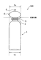
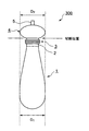
図1、図2、図3は、それぞれ本発明の無菌充填用ブロー成形容器の一実施例の構成を示す正面図である。
また、図4は、従来の無菌充填用ブロー成形容器の一例の構成を示す正面図である。
そして、図5は、本発明の無菌充填用ブロー成形容器の殺菌方法に用いる殺菌ゾーンの一実施例の構造を説明する概略図である。
図6は、図5に示した殺菌ゾーンにおいて、無菌充填用ブロー成形容器を紫外線照射により殺菌する状態を説明する部分拡大図であり、(イ)は容器の上部側から見た側面図、(ロ)は容器の正面側から見た図である。
【0023】
図1に示した無菌充填用ブロー成形容器100は、その本体部を通常の丸形のブローボトルと同様に形成したものであり、横断面が円形で底部が略フラットとなる有底筒状の容器本体部1と、その上部に連続し外周にネジ部3が設けられた口頸部2と、口頸部2の上に切り取り可能に設けられた上部に細管部5を有する閉鎖部4とで形成され、閉鎖部4の外径D2 は、容器本体部1の最大胴部の外径D1 と同一寸法となるように形成され、また、該容器100のブロー成形の際には、内部に無菌のエアが吹き込まれて成形されると共に、細管部5が熱溶着されて密閉され、内部が無菌のエアで満たされ、無菌状態に維持されるように形成して構成したものである。
【0024】
このような構成を採ることにより、無菌充填用ブロー成形容器100は、内部が無菌状態に形成されているので、無菌充填装置で使用する際には、容器100の外面のみを殺菌すればよく、また、容器外面の殺菌後、内容物の充填前に閉鎖部4をその下端の切断位置で切り取ることにより、口頸部2の上部が開口され、無菌状態で内容物を充填することができる。
また、無菌充填装置の殺菌ゾーンで容器100の外面を殺菌する際には、容器100の閉鎖部4の外径と容器本体部1の最大胴部の外径が同一寸法となる円形に形成されているので、前述したように、搬送コンベアに設けられた回転ロールと回転ロールの間に容器100を寝かせて乗せ、回転ロールの回転で容器100を回転させながら搬送しても容器100が傾いて不安定になることがなく、安定した状態で容器100を搬送することができ、搬送中に上部から、例えば紫外線を照射して容器100の外面を均一に殺菌することができる。
【0025】
図2に示した無菌充填用ブロー成形容器200は、前記図1に示した無菌充填用ブロー成形容器100の構成において、底部の形状を丸みを持つ形状に変更して構成したものであり、その他の部分は総て図1に示したブロー成形容器100と同様に形成して構成したものである。
【0026】
このような構成の無菌充填用ブロー成形容器200は、半流動性の内容物を充填し、内容物を取り出す際には、容器本体部1を押しつぶして、内容物を押し出すようにして取り出す場合に好適に使用できるものであり、そのためには容器本体部1を押しつぶしが可能なように薄肉に形成することが好ましく、また、内容物を小出しに取り出して使用する場合、内容物が常に口頸部2の近辺に滞留するように容器200を倒立させて置くことが好ましく、そのためには、例えば口頸部2に装着するキャップ(図示せず)の天面をフラットで大きめに形成して、キャップを下にして容器200を立てられるように構成することが好ましい。
また、このような使用方法で容器200を使用する場合、容器200の底部が半球状に丸みを持つ形状に形成されているので、フラットな形状の底部と比較して、内容物を押し出す際、偏平に押しつぶしやすく、内容物の残留によるロスを少なくすることができる。
尚、底部以外の部分については、総て図1に示したブロー成形容器100と同様に形成されているので、図1に示したブロー成形容器100で説明した作用効果と同様な作用効果を得ることができる。
【0027】
図3に示した無菌充填用ブロー成形容器300は、前記図1に示した無菌充填用ブロー成形容器100の構成において、前記図2に示したブロー成形容器200と同様に、底部の形状を丸みを持つ形状に変更すると共に、更に容器本体部1を、その中間部近辺から上部の口頸部2に向かって径が徐々に小さくなる形状に変更して構成したものであり、その他の部分、即ち、口頸部2から上の部分は総て図1に示したブロー成形容器100と同様に形成して構成したものである。
【0028】
このような構成の無菌充填用ブロー成形容器300も、前記図2に示したブロー成形容器200と同様に、半流動性の内容物を充填し、内容物を取り出す際には、容器本体部1を押しつぶして、内容物を押し出すようにして取り出す場合に好適に使用できるものであり、そのためには、容器本体部1を押しつぶしが可能なように薄肉に形成することが好ましく、また、内容物を小出しに取り出して使用する場合、内容物が常に口頸部2の近辺に滞留するように容器300を倒立させて置くことが好ましく、そのためには、例えば口頸部2に装着するキャップ(図示せず)の天面をフラットで大きめに形成して、キャップを下にして容器300を立てられるように構成することが好ましい。
【0029】
このような構成を採った場合も、閉鎖部4の外径D2 は、容器本体部1の最大胴部の外径D1 と同一寸法となるように形成されているので、前記殺菌ゾーンの搬送コンベアの二本の平行な回転ロールの間に、容器300を寝かせて乗せ、回転ロールで容器300を回転させながら搬送しても、容器300は上部の閉鎖部4と容器本体部1の最大胴部である容器本体の下部とで回転ロールに支えられるので、安定した状態で容器300を回転させながら搬送することができ、その外面を紫外線照射などにより確実に殺菌することができる。
また、容器本体部1が、その中間部近辺から上部の口頸部2に向かって径が徐々に小さくなり口頸部2の径に一致する形状に形成されているので、充填された内容物を押し出して取り出す際、容器300の上部でもデッドスペースの発生をなくすことができ、一層内容物の残留によるロスを少なくすることができる。
また、前記変更点以外については、前記図1に示したブロー成形容器100と同じ構成であるため、図1に示したブロー成形容器100で説明した作用効果と同様な作用効果を得ることができる。
【0030】
図4は、従来の無菌充填用ブロー成形容器の一例の構成を示す正面図であり、図4に示した無菌充填用ブロー成形容器は、前記図2に示した本発明の無菌充填用ブロー成形容器200と対比して、口頸部2の上に設けた閉鎖部4の形状のみが、その外径D2 が容器本体部1の最大胴部の外径D1 よりも小さくなるように形成されて構成されている。
このような構成の容器は、ブロー成形の際、無菌のエアを吹き込んで容器の内部を無菌状態に形成すると共に、細管部5を熱溶着して密閉し、容器内部を無菌状態に維持できるように構成した点では本発明の無菌充填用ブロー成形容器と同じであるが、容器の外面を殺菌するために、従来は無菌充填装置の殺菌ゾーンで容器の口頸部2の下部などを把持し、容器の外面に過酸化水素水などの殺菌剤の吹きつけを行っており、その際、閉鎖部4が殺菌剤の吹きつけの邪魔にならないように、閉鎖部4の外径は小さく形成されている。
しかし、このような構成のブロー成形容器は、特に内容物の押し出しを容易にするため、容器本体部1を薄肉に形成するとこの部分が軽くなり、容器の口頸部2および閉鎖部4は、比較的厚肉で重いため、容器の外面の殺菌に紫外線などを用いる本発明の無菌充填用ブロー成形容器の殺菌方法では、容器を搬送コンベアの回転ロールの間に寝かせて乗せ回転させながら搬送する際、容器の上下で質量のバランスが悪くなり、スムーズに回転させることができず、均一に紫外線照射を行うことができないため好ましくなかった。
【0031】
次に、図5は、本発明の無菌充填用ブロー成形容器の殺菌方法に用いる殺菌ゾーンの一実施例の構造を説明する概略図であり、図6は、図5に示した殺菌ゾーンにおいて、無菌充填用ブロー成形容器を紫外線照射により殺菌する状態を説明する部分拡大図であり、(イ)は容器の上部側から見た側面図で、(ロ)は容器の正面側から見た図である。
【0032】
図5に示した殺菌ゾーン10は、上方に配置され下方に向けて殺菌用の紫外線を照射する紫外線照射装置11と、その下を走行する容器の搬送コンベア12とで構成され、搬送コンベア12は、多数の回転ロール13が所定の間隔で平行に配置され、その回転ロール13と回転ロール13の間に、図6の(イ)、(ロ)にも示すように、本発明の無菌充填用ブロー成形容器16を寝かせて乗せ、ブロー成形容器16の搬送を行うと同時に、その回転ロール13の回転をブロー成形容器16の周面に伝達してブロー成形容器16を周方向に回転させるように構成されている。
搬送コンベア12は、搬送コンベア駆動部14によりその走行速度を調節して駆動され、また、回転ロール13の回転は、別に設けた接触ベルトまたはチェーン方式で行われ、それを駆動する回転ロールの回転駆動部15で回転速度を調節して行われる。この回転速度の調節は、ブロー成形容器16が紫外線照射装置の下を搬送される間に少なくとも一回転するように調節すればよく、それによりブロー成形容器16の外周面全体に紫外線を照射して殺菌することができる。
【0033】
また、図6の(イ)、(ロ)に示すように、本発明の無菌充填用ブロー成形容器の殺菌方法では、搬送コンベアに設けられた二本の回転ロール13の間に、予め内部が無菌状態に形成されたブロー成形容器16を寝かせて乗せ、紫外線照射装置で上方から紫外線を照射しつつ、ブロー成形容器16を回転させながら搬送することができるので、搬送中、ブロー成形容器16の上側は完全にオープンな状態であり、ブロー成形容器16の外面全体を確実に殺菌することができる。
【0034】
また、この時、ブロー成形容器16の上部、即ち、口頸部の上には、容器本体部の最大胴部の外径と同じ外径の前記閉鎖部が設けられているので、搬送中、ブロー成形容器16は、最大胴部の外面と閉鎖部の外面の両方で回転ロール13に支えられる。従って、容器本体部が薄肉に形成され、ブロー成形容器16の上部と下部の質量バランスが悪い場合でも、回転ロール13の間でブロー成形容器16が傾いて不安定になることがなく、安定した状態でブロー成形容器16を回転させながら搬送することができ、ブロー成形容器16の外面全体を確実に殺菌することができるものである。
【0035】
【実施例】
以下に、実施例および比較例を挙げて、本発明を更に具体的に説明する。
(実施例1)
図1に示した構成の無菌充填用ブロー成形容器を、ブロー成形の樹脂にポリエチレンを用いて、以下の寸法で作製し、実施例1の無菌充填用ブロー成形容器とした。
(1) 容器本体部1の高さ130mm
(2) 容器本体部1の最大胴部の外径(D1 )57mm
(3) 口頸部2の長さ20mm
(4) 口頸部2のネジ部3を含む部分の外径33mm
(5) 閉鎖部4の長さ33mm
(6) 閉鎖部4の外径(D2 )57mm
(7) 細管部の長さ8mm
(8) 容器本体部1の肉厚0.7mm
【0036】
(実施例2)
図2に示した構成の無菌充填用ブロー成形容器を、ブロー成形の樹脂にポリエチレンを用いて、以下の寸法で作製し、実施例2の無菌充填用ブロー成形容器とした。
(1) 容器本体部1の高さ130mm
(2) 容器本体部1の最大胴部の外径(D1 )57mm
(3) 口頸部2の長さ20mm
(4) 口頸部2のネジ部3を含む部分の外径33mm
(5) 閉鎖部4の長さ33mm
(6) 閉鎖部4の外径(D2 )57mm
(7) 細管部の長さ8mm
(8) 容器本体部1の肉厚0.3mm
この容器本体部1の肉厚0.3mmは、押しつぶし可能な厚みである。
【0037】
(実施例3)
図3に示した構成の無菌充填用ブロー成形容器を、ブロー成形の樹脂にポリエチレンを用いて、以下の寸法で作製し、実施例3の無菌充填用ブロー成形容器とした。
(1) 容器本体部1の高さ130mm
(2) 容器本体部1の最大胴部の外径(D1 )57mm
(3) 口頸部2の長さ20mm
(4) 口頸部2のネジ部3を含む部分の外径33mm
(5) 閉鎖部4の長さ33mm
(6) 閉鎖部4の外径(D2 )57mm
(7) 細管部の長さ8mm
(8) 容器本体部1の肉厚0.33mm
この容器本体部1の肉厚0.33mmも、押しつぶし可能な厚みである。
【0038】
(比較例1)
図4に示した構成の無菌充填用ブロー成形容器を、ブロー成形の樹脂にポリエチレンを用いて、以下の寸法で作製し、比較例1の無菌充填用ブロー成形容器とした。
(1) 容器本体部1の高さ130mm
(2) 容器本体部1の最大胴部の外径(D1 )57mm
(3) 口頸部2の長さ20mm
(4) 口頸部2のネジ部3を含む部分の外径33mm
(5) 閉鎖部4の長さ33mm
(6) 閉鎖部4の外径(D2 )33mm
(7) 細管部5の長さ8mm
(8) 容器本体部1の肉厚0.3mm
この容器本体部1の肉厚0.3mmは、実施例2の容器と同じで押しつぶし可能な厚みである。
【0039】
以上のように作製した実施例1〜3および比較例1の無菌充填用ブロー成形容器をそれぞれ図5に示した構成の殺菌ゾーン10に通して、その搬送コンベア12による搬送適性と紫外線照射による殺菌効果を試験した結果、比較例1の無菌充填用ブロー成形容器は、容器本体部1が薄肉であり、また、閉鎖部4の外径(D2 )が容器本体部1の最大胴部の外径(D1 )よりも小さいため、搬送コンベア12の回転ロール13の間でブロー成形容器が回転された時、容器が傾いて浮き上がり、正常に回転させることができず搬送適性は不良であった。
これに対して実施例1〜3の無菌充填用ブロー成形容器は、いずれも口頸部2の上に容器本体部1の最大胴部の外径(D1 )と同一外径(D2 )の閉鎖部4が設けられているので、搬送コンベア12の回転ロール13の間でブロー成形容器は安定した状態で回転しながら搬送され、ブロー成形容器の外面を確実に殺菌することができた。
【0040】
【発明の効果】
以上、詳しく説明したように、本発明によれば、ブロー成形により成形される横断面が円形状のボトル状容器であって、該容器が、ブロー成形の際、内部が無菌状態に形成され、且つその無菌状態が維持されるように、容器の口頸部の上に切り取り可能に設けられた閉鎖部を利用して密閉された形状に成形されると共に、該容器を無菌充填装置で使用する際には、無菌充填装置の充填部の前ゾーンに容器の外面を殺菌するための紫外線照射装置などの簡便な殺菌装置を取り付けることにより、容器の外面を確実に殺菌することができ、無菌充填装置の小型化とその操作の簡略化を実現できると共に、該容器が細口のボトル状容器であっても、確実に且つ生産性よく無菌充填を行うことのできる無菌充填用ブロー成形容器と、その殺菌方法を提供できる効果を奏する。
【図面の簡単な説明】
【図1】本発明の無菌充填用ブロー成形容器の第1の実施例の構成を示す正面図である。
【図2】本発明の無菌充填用ブロー成形容器の第2の実施例の構成を示す正面図である。
【図3】本発明の無菌充填用ブロー成形容器の第3の実施例の構成を示す正面図である。
【図4】従来の無菌充填用ブロー成形容器の一例の構成を示す正面図である。
【図5】本発明の無菌充填用ブロー成形容器の殺菌方法に用いる殺菌ゾーンの一実施例の構造を説明する概略図である。
【図6】図5に示した殺菌ゾーンにおいて、無菌充填用ブロー成形容器を紫外線照射により殺菌する状態を説明する部分拡大図であり、(イ)は容器の上部側から見た側面図、(ロ)は容器の正面側から見た図である。
【符号の説明】
1 有底筒状の容器本体部
2 口頸部
3 ネジ部
4 閉鎖部
5 細管部
10 殺菌ゾーン
11 紫外線照射装置
12 搬送コンベア
13 回転ロール
14 搬送コンベア駆動部
15 回転ロールの回転駆動部
16 ブロー成形容器
D1 胴部の最大外径
D2 閉鎖部の外径
100、200、300 ブロー成形容器[0001]
BACKGROUND OF THE INVENTION
The present invention relates to a blow-molded container for aseptic filling and a sterilization method therefor, and more specifically, a round bottle-shaped container formed by blow molding, and the container is in a sterile state during blow molding. Formed and sealed to maintain its sterility, and when used in an aseptic filling device, to sterilize the outer surface of the container in the front zone of the filling portion of the aseptic filling device The present invention relates to a blow molded container for aseptic filling that can be reliably and aseptically filled by simply attaching a simple sterilizing apparatus, and a method for sterilizing the same.
[0002]
[Prior art]
Conventionally, beverages such as milk, juice, coffee, topping fruit, whipped cream, etc., are often used aseptic filling packaging to maintain the freshness of the taste and color and to improve the storage stability. Yes.
In such aseptic filling packaging, various containers such as injection molded containers, blow molded containers, BIB-type containers, liquid paper containers, etc., are appropriately selected and used depending on the contents and their applications. ing.
Among these, blow-molded containers, particularly direct blow-molded containers, have good productivity, can be easily produced at a relatively low cost, and can easily adjust the container thickness, so that beverages etc. The shape-retaining bottle filled with the above liquid is also suitable for use as a flexible bottle-shaped container that is filled with a semi-fluid content such as a paste and is extruded while being crushed. ing.
[0003]
只 When such a bottle-shaped blow molded container is used for aseptic filling and packaging, as a matter of course, in the aseptic filling apparatus, the container needs to be in an aseptic state on both the inner surface and the outer surface. A sterilization step is provided in front of the filling unit of the filling device to sterilize the inner and outer surfaces of the container.
Such a sterilization process is usually performed by a process of spraying, cleaning, and drying a sterilizing agent (for example, hydrogen peroxide solution). When such a sterilization method is applied to the inner and outer surfaces of a container, the apparatus is At the same time, there was a problem that the equipment cost was expensive.
In particular, when the container is a narrow-bottle, there is a problem that it is difficult to uniformly sterilize and clean the container by inserting a nozzle for spraying the sterilizing agent or cleaning water into the container.
[0004]
As a method for solving a part of such problems, the present applicant has previously proposed a method for forming a sterile blow-molded container that can be sealed with the inside of the container maintained in a sterile state. That is, “a blow molding air nozzle is surrounded by a blow molding resin to form a cylindrical parison, the parison is connected to the blow head, the parison is enclosed, the mold is closed, and the air nozzle is There is an aseptic blow molding method characterized in that aseptic air is blown into a parison to perform blow molding, and then the parison between the molded part and the blow head is sealed and separated without filling the contents ”( For example, see Patent Document 1).
[0005]
By adopting such an aseptic blow molding method, even a narrow mouth blow molded container, the inside can be easily made sterile and the sterile blow molded container capable of maintaining the sterile condition. Can be provided.
By using such a sterile blow-molded container with an aseptic filling device, there is no need to sterilize the inside of the container, so only the outer surface of the container needs to be sterilized, and the sterilization process of the aseptic filling device can be simplified. And the space of the apparatus can be made compact.
[0006]
Furthermore, the present applicant has simplified the sterilization process by using a sterile blow-molded container in which the inside is formed in a sterile state and sealed so as to maintain the sterile state as follows. An aseptic filling device has been proposed previously.
That is, “an aseptic filling device for a blow-molded container supplied in an aseptically sealed state, comprising a container holder provided to travel along a predetermined path, and the container holder A container transport device that holds and transports the container, a container supply station that supplies the container to the container holder, the first outside air blocking zone, and the container, which are disposed along the travel path of the container holder of the container transport device A sterilization zone for applying a disinfectant to the outer surface, a cleaning zone for applying a cleaning liquid to the sterilized container for cleaning, a drying zone for drying the cleaned container, and a cutting zone for cutting and opening the container head A filling zone for filling the contents into the container, a sealing zone for joining and sealing the sheet material to the container opening, a second outside air blocking zone, and a container discharge station for discharging the container held by the container holder The The sterilization zone to the sealing zone, at least the container passage part through which the entire container passes is made into a sterile chamber in which positive pressure is maintained with sterile air, and the first and second outside air blocking zones are held at negative pressure. Aseptic filling device characterized by having a negative pressure chamber ”(see, for example, Patent Document 2).
[0007]
[Patent Document 1]
Japanese Patent Publication No. 7-45171 (
[Patent Document 2]
Japanese Patent No. 2684633 (
[0008]
[Problems to be solved by the invention]
By using the aseptic filling device as described above, the inside of the blow molded container is formed in advance in a sterile state and sealed so that the sterile state is maintained. Only the outer surface of the container needs to be sterilized before filling, and even a narrow blow molded container can be sterilized easily and at the same time simplify the sterilization process.
However, even in such an aseptic filling apparatus, a sterilizing agent such as hydrogen peroxide is used for sterilizing the outer surface of the container, so that at least a sterilizing zone for applying a sterilizing agent to the outer surface of the container and a cleaning liquid in the sterilized container And a drying zone for drying the container after cleaning, which requires a certain amount of space, and there are complicated and time-consuming problems such as management of sterilization conditions and equipment maintenance. Therefore, further convenience has been desired.
[0009]
As a method for solving such a problem, there is a method of applying an ultraviolet sterilization method or an electron beam sterilization method to sterilize the outer surface of the container. In these sterilization methods, irradiation of ultraviolet rays or electron beams is performed from one direction for the convenience of the apparatus, and therefore it is necessary to rotate the container in order to uniformly irradiate the outer surface of the container. Furthermore, in order to irradiate in an open state so as not to cause shadows during rotation, for example, the container conveyor is composed of a number of rotating rolls, and the containers are placed between a pair of parallel rotating rolls. There is a method of rotating the roll by transmitting it to the container.
However, even when such an irradiation method is adopted, when the container has the shape shown in the above Japanese Patent Publication No. 7-45171 and Japanese Patent No. 2684633, the upper part of the container including the mouth and neck is relatively heavy. In addition, since the container is not in contact with the rotating roll, the container becomes unstable during rotation, and uniform irradiation becomes difficult.
[0010]
The present invention has been made to solve the above-described problems, and an object of the present invention is a round bottle-shaped container formed by blow molding, and the container is blow-molded. In this case, the inside is formed in a sterile state and is molded into a sealed shape so that the sterile state is maintained. When the container is used in a sterile filling device, the filling portion of the sterile filling device is By installing a simple sterilization device for sterilizing the outer surface of the container in the front zone, even if the container is a narrow bottle-shaped container, the aseptic filling blow can be performed reliably and with high productivity. The object is to provide a molded container and a sterilization method thereof.
[0011]
[Means for Solving the Problems]
The above problems can be solved by the following present invention.
That is, the invention described in
[0012]
By adopting such a configuration, the blow molding container for aseptic filling of the present invention is molded by aseptic air being blown into the inside during blow molding, and can be cut out on the mouth and neck of the container. Since the narrow tube part on the provided closed part is heat-welded, the inside is filled with aseptic air and the inside is sealed in a sterile state. Therefore, when aseptically filling the contents, the aseptic filling device In this case, only the outer surface of the container can be sterilized, and then the closure part is cut off to open the mouth and neck part to fill the contents.
Therefore, even in a bottle-shaped container with a narrow mouth, it is not necessary to sterilize the inside of the container with an aseptic filling device, so that the contents can be easily aseptically filled.
[0013]
Further, when the outer surface of the container is sterilized by the aseptic filling device, the closing part is formed so as to have the same outer diameter as the outer diameter of the largest body part of the container main body part. The container is placed between two rotating rolls of a conveyor that is arranged in parallel at an interval of the container, and the rotation of the rotating roll is transmitted to the circumferential surface of the container simultaneously with the conveyance of the container, so that the container is circumferentially moved. Even if the container is rotated, the container is supported by the rotating roll at both the body part and the closing part, so that the container is not inclined and unstable, and the container can be conveyed while rotating in a stable state. it can.
Therefore, in combination with such a conveyer, by using an ultraviolet irradiation device or an electron beam irradiation device as a sterilizing means, the outer surface of the container is uniformly irradiated with ultraviolet rays or an electron beam to reliably sterilize the outer surface of the container. Therefore, it is not necessary to use a conventional bactericidal agent (hydrogen peroxide solution), and steps such as cleaning and drying are not necessary, and the process can be simplified and the apparatus can be downsized.
[0014]
In the present invention, the shape of the body part of the blow molded container may be circular as long as the cross section is circular. For example, the shape of the main part of the blow molded container is the same as that of a normal round bottle having a substantially flat bottom as shown in FIG. In addition, a shape with a rounded bottom as shown in FIG. 2, in this case, the top surface of the cap can be formed flat and slightly large so that the container can be erected with the cap down. Furthermore, such as a deformation type shape in which the diameter gradually decreases in the upper direction as shown in FIG. 3, a shape that can be laid down between the two rotating rolls for conveyance and rotated stably. If it is, it can form arbitrarily.
[0015]
The invention described in
[0016]
By adopting such a configuration, in addition to the action and effect of the invention described in
[0017]
The invention described in
[0018]
For the gas barrier layer of the intermediate layer, for example, a gas barrier resin such as saponified ethylene-vinyl acetate copolymer (hereinafter sometimes referred to as EVOH) or MXD6 (polymetaxylylene adipamide) is preferably used. Can be used.
In particular, when EVOH is used for the gas barrier layer, the gas barrier property of EVOH decreases when moisture is absorbed. Therefore, a moisture-proof resin such as polyethylene, polypropylene, or a copolymer thereof is laminated and blown on both sides of the EVOH layer. By forming a molded container, excellent gas barrier properties can be imparted to the container.
[0019]
Therefore, by adopting the configuration as described above, in addition to the operational effects of the invention described in
[0020]
The invention described in
[0021]
By adopting such a sterilization method, it is no longer necessary to use a conventional sterilizing agent such as hydrogen peroxide water for sterilization of the container. Cleaning and drying steps after sterilization are not required, and the space for the aseptic filling device can be made compact.
In the above sterilization method, an ultraviolet irradiation device is used for sterilization, but it can also be sterilized by the same method using an electron beam irradiation device.
[0022]
DETAILED DESCRIPTION OF THE INVENTION
Embodiments of the present invention will be described below with reference to the drawings.
1, FIG. 2 and FIG. 3 are front views showing the construction of one embodiment of the aseptic filling blow molded container of the present invention.
FIG. 4 is a front view showing the structure of an example of a conventional aseptic filling blow-molded container.
FIG. 5 is a schematic view illustrating the structure of one embodiment of a sterilization zone used in the sterilization method for aseptic filling blow-molded containers of the present invention.
FIG. 6 is a partially enlarged view for explaining a state in which the aseptic filling blow-molded container is sterilized by ultraviolet irradiation in the sterilization zone shown in FIG. 5, and (A) is a side view as seen from the upper side of the container. (B) is a view as seen from the front side of the container.
[0023]
The aseptic filling blow-molded
[0024]
By adopting such a configuration, the aseptic filling blow-molded
Further, when the outer surface of the
[0025]
The aseptic filling blow molded
[0026]
The aseptic filling blow-molded
In addition, when using the
Since the portions other than the bottom are all formed in the same manner as the blow-molded
[0027]
The aseptic filling blow-molded
[0028]
Similarly to the blow-molded
[0029]
Even when such a configuration is adopted, the outer diameter D of the closing
Moreover, since the container
Moreover, since it is the same structure as the
[0030]
FIG. 4 is a front view showing a configuration of an example of a conventional aseptic filling blow-molded container, and the aseptic filling blow-molded container shown in FIG. 4 is the aseptic filling blow-molded container of the present invention shown in FIG. In contrast to the
The container having such a configuration can be configured so that aseptic air is blown during blow molding to form the inside of the container in a sterile state, and the
However, in the blow molded container having such a configuration, in particular, in order to facilitate the extrusion of the contents, when the container
[0031]
Next, FIG. 5 is a schematic diagram illustrating the structure of one embodiment of the sterilization zone used in the sterilization method for aseptic filling blow-molded containers of the present invention, and FIG. 6 shows the sterilization zone shown in FIG. It is the elements on larger scale explaining the state which sterilizes the blow molding container for aseptic filling by ultraviolet irradiation, (A) is the side view seen from the upper part side of a container, (B) is the figure seen from the front side of the container is there.
[0032]
The
The
[0033]
Further, as shown in FIGS. 6A and 6B, in the aseptic filling blow molded container sterilization method of the present invention, the interior is previously provided between the two
[0034]
At this time, since the closing part having the same outer diameter as the outer diameter of the largest body part of the container main body part is provided on the upper part of the blow molded
[0035]
【Example】
Hereinafter, the present invention will be described more specifically with reference to examples and comparative examples.
(Example 1)
The aseptic filling blow-molded container having the configuration shown in FIG. 1 was produced using polyethylene as a blow-molded resin with the following dimensions to obtain the aseptic filling blow-molded container of Example 1.
(1) The height of the
(2) Outer diameter of the largest body of the container body 1 (D 1 57mm
(3) Length of mouth and
(4) The outer diameter of the part including the
(5) Length of the
(6) Outer diameter of closure 4 (D 2 57mm
(7) Length of narrow tube part 8mm
(8) Wall thickness 0.7mm of the
[0036]
(Example 2)
The aseptic filling blow-molded container having the configuration shown in FIG. 2 was produced using polyethylene as a blow-molded resin with the following dimensions to obtain the aseptic filling blow-molded container of Example 2.
(1) The height of the
(2) Outer diameter of the largest body of the container body 1 (D 1 57mm
(3) Length of mouth and
(4) The outer diameter of the part including the
(5) Length of the
(6) Outer diameter of closure 4 (D 2 57mm
(7) Length of narrow tube part 8mm
(8) Thickness of
The thickness 0.3 mm of the container
[0037]
(Example 3)
The aseptic filling blow-molded container having the configuration shown in FIG. 3 was produced using polyethylene as a blow-molded resin with the following dimensions to obtain the aseptic filling blow-molded container of Example 3.
(1) The height of the
(2) Outer diameter of the largest body of the container body 1 (D 1 57mm
(3) Length of mouth and
(4) The outer diameter of the part including the
(5) Length of the
(6) Outer diameter of closure 4 (D 2 57mm
(7) Length of narrow tube part 8mm
(8) The thickness of the
The wall thickness 0.33 mm of the container
[0038]
(Comparative Example 1)
The aseptic filling blow-molded container having the configuration shown in FIG. 4 was produced using polyethylene as a blow-molded resin with the following dimensions to obtain the aseptic filling blow-molded container of Comparative Example 1.
(1) The height of the
(2) Outer diameter of the largest body of the container body 1 (D 1 57mm
(3) Length of mouth and
(4) The outer diameter of the part including the
(5) Length of the
(6) Outer diameter of closure 4 (D 2 ) 33mm
(7) Length of narrow tube part 8mm
(8) The thickness of the
The thickness 0.3 mm of the container
[0039]
The blow-molded containers for aseptic filling of Examples 1 to 3 and Comparative Example 1 produced as described above are passed through the
On the other hand, the aseptic filling blow-molded containers of Examples 1 to 3 all have the outer diameter (D 1 ) Same outer diameter (D 2 ) Is provided between the
[0040]
【The invention's effect】
As described above in detail, according to the present invention, the cross section formed by blow molding is a circular bottle-shaped container, and the container is formed in an aseptic state during blow molding, In order to maintain the sterility of the container, the container is molded into a hermetically sealed shape by using a closing portion provided on the mouth and neck of the container so as to be cut off, and the container is used in an aseptic filling apparatus. In this case, the outer surface of the container can be reliably sterilized by attaching a simple sterilization device such as an ultraviolet irradiation device for sterilizing the outer surface of the container to the zone in front of the filling part of the aseptic filling device. A blow molding container for aseptic filling that can realize downsizing of the apparatus and simplification of its operation, and can perform aseptic filling reliably and with high productivity even when the container is a narrow-bottled container, and its Proposed sterilization method It achieves the effect can be.
[Brief description of the drawings]
FIG. 1 is a front view showing the configuration of a first embodiment of a blow-molded container for aseptic filling according to the present invention.
FIG. 2 is a front view showing the configuration of a second embodiment of the aseptic filling blow molded container of the present invention.
FIG. 3 is a front view showing the configuration of a third embodiment of the aseptic filling blow molded container of the present invention.
FIG. 4 is a front view showing a configuration of an example of a conventional aseptic filling blow-molded container.
FIG. 5 is a schematic view illustrating the structure of an embodiment of a sterilization zone used in the method for sterilizing a blow molded container for aseptic filling according to the present invention.
6 is a partially enlarged view for explaining a state in which the aseptic filling blow-molded container is sterilized by ultraviolet irradiation in the sterilization zone shown in FIG. 5, (A) is a side view seen from the upper side of the container; (B) is a view as seen from the front side of the container.
[Explanation of symbols]
1 Bottomed cylindrical container body
2 mouth and neck
3 Screw part
4 Closure
5 Capillary section
10 Sterilization zone
11 UV irradiation equipment
12 Conveyor
13 Rotating roll
14 Conveyor drive unit
15 Rotating roll rotation drive
16 Blow molded container
D 1 Maximum outer diameter of the trunk
D 2 Closure outer diameter
100, 200, 300 Blow molded containers
Claims (4)
Priority Applications (1)
| Application Number | Priority Date | Filing Date | Title |
|---|---|---|---|
| JP2003176587A JP4170833B2 (en) | 2003-06-20 | 2003-06-20 | Blow molded container for aseptic filling and sterilization method thereof |
Applications Claiming Priority (1)
| Application Number | Priority Date | Filing Date | Title |
|---|---|---|---|
| JP2003176587A JP4170833B2 (en) | 2003-06-20 | 2003-06-20 | Blow molded container for aseptic filling and sterilization method thereof |
Publications (2)
| Publication Number | Publication Date |
|---|---|
| JP2005008243A JP2005008243A (en) | 2005-01-13 |
| JP4170833B2 true JP4170833B2 (en) | 2008-10-22 |
Family
ID=34099435
Family Applications (1)
| Application Number | Title | Priority Date | Filing Date |
|---|---|---|---|
| JP2003176587A Expired - Lifetime JP4170833B2 (en) | 2003-06-20 | 2003-06-20 | Blow molded container for aseptic filling and sterilization method thereof |
Country Status (1)
| Country | Link |
|---|---|
| JP (1) | JP4170833B2 (en) |
Families Citing this family (4)
| Publication number | Priority date | Publication date | Assignee | Title |
|---|---|---|---|---|
| DE102007017938C5 (en) * | 2007-04-13 | 2017-09-21 | Khs Gmbh | Container manufacturing apparatus and mold production method |
| JP5448319B2 (en) * | 2007-10-03 | 2014-03-19 | キョーラク株式会社 | Hollow body with deburring structure |
| JP6178620B2 (en) * | 2013-05-24 | 2017-08-09 | 靜甲株式会社 | Method and apparatus for forming opening of soft container |
| CN109436469B (en) * | 2018-12-14 | 2020-02-14 | 江苏新美星包装机械股份有限公司 | Rotary electron beam sterilization device |
-
2003
- 2003-06-20 JP JP2003176587A patent/JP4170833B2/en not_active Expired - Lifetime
Also Published As
| Publication number | Publication date |
|---|---|
| JP2005008243A (en) | 2005-01-13 |
Similar Documents
| Publication | Publication Date | Title |
|---|---|---|
| US20230234824A1 (en) | Hybrid method for processing containers | |
| JP6507678B2 (en) | Method and apparatus for sterilizing composite preform, method and apparatus for sterilizing composite container, composite preform and composite container | |
| US20100005760A1 (en) | Method and arrangement for treating bags to be filled with a product prior to filling the bags with a product | |
| CN105752418A (en) | Drink filling method and drink filling device | |
| JP4111547B2 (en) | Device for sterilizing spout assembly of containers | |
| BR112013002716B1 (en) | PROCESS TO PRODUCE A CONTAINER | |
| JP2003237742A (en) | Method of aseptically filling pouch having spout | |
| US20180297302A1 (en) | Method for reducing the microbiological loading of container products | |
| US20100221146A1 (en) | Method of aseptically treating, forming, filling, and sealing flexible bag packages in a bag packaging machine | |
| JP4170833B2 (en) | Blow molded container for aseptic filling and sterilization method thereof | |
| EP1957370B1 (en) | A method and an apparatus for filling of packages | |
| BR112013002713B1 (en) | PROCESS TO PRODUCE A CONTAINER AND CONTAINER | |
| JP4590805B2 (en) | Aseptic filling method for pouch with spout | |
| JP2015127233A (en) | Composite paper container and packing/filling machine | |
| JP6119806B2 (en) | Aseptic bagging method and apparatus | |
| JP4046516B2 (en) | Air conveyor type container sterilizer | |
| JPH09240629A (en) | Method and apparatus for sterilizing paper vessel in germless filling apparatus | |
| JPH0148140B2 (en) | ||
| JPH07147949A (en) | Aseptically packing method for stoppered bag container | |
| JP2015101387A (en) | Packaging filling machine | |
| US20080008403A1 (en) | Aseptic package | |
| JP2013086848A (en) | Sterile filling method of container with tap | |
| JP6886644B2 (en) | Cap sterilizer, content filling system, cap sterilization method and content filling method | |
| JPH11171101A (en) | Aseptically filling method for inner bag of bag-in-box | |
| JP7447424B2 (en) | Aseptic filling machine and aseptic filling method |
Legal Events
| Date | Code | Title | Description |
|---|---|---|---|
| A621 | Written request for application examination |
Free format text: JAPANESE INTERMEDIATE CODE: A621 Effective date: 20060525 |
|
| A977 | Report on retrieval |
Free format text: JAPANESE INTERMEDIATE CODE: A971007 Effective date: 20080725 |
|
| TRDD | Decision of grant or rejection written | ||
| A01 | Written decision to grant a patent or to grant a registration (utility model) |
Free format text: JAPANESE INTERMEDIATE CODE: A01 Effective date: 20080805 |
|
| A01 | Written decision to grant a patent or to grant a registration (utility model) |
Free format text: JAPANESE INTERMEDIATE CODE: A01 |
|
| A61 | First payment of annual fees (during grant procedure) |
Free format text: JAPANESE INTERMEDIATE CODE: A61 Effective date: 20080807 |
|
| FPAY | Renewal fee payment (event date is renewal date of database) |
Free format text: PAYMENT UNTIL: 20110815 Year of fee payment: 3 |
|
| R150 | Certificate of patent or registration of utility model |
Ref document number: 4170833 Country of ref document: JP Free format text: JAPANESE INTERMEDIATE CODE: R150 Free format text: JAPANESE INTERMEDIATE CODE: R150 |
|
| FPAY | Renewal fee payment (event date is renewal date of database) |
Free format text: PAYMENT UNTIL: 20110815 Year of fee payment: 3 |
|
| FPAY | Renewal fee payment (event date is renewal date of database) |
Free format text: PAYMENT UNTIL: 20120815 Year of fee payment: 4 |
|
| FPAY | Renewal fee payment (event date is renewal date of database) |
Free format text: PAYMENT UNTIL: 20120815 Year of fee payment: 4 |
|
| FPAY | Renewal fee payment (event date is renewal date of database) |
Free format text: PAYMENT UNTIL: 20130815 Year of fee payment: 5 |
|
| EXPY | Cancellation because of completion of term |