JP4169440B2 - Printer assembly and printer - Google Patents
Printer assembly and printer Download PDFInfo
- Publication number
- JP4169440B2 JP4169440B2 JP26736699A JP26736699A JP4169440B2 JP 4169440 B2 JP4169440 B2 JP 4169440B2 JP 26736699 A JP26736699 A JP 26736699A JP 26736699 A JP26736699 A JP 26736699A JP 4169440 B2 JP4169440 B2 JP 4169440B2
- Authority
- JP
- Japan
- Prior art keywords
- thermal head
- support
- platen roller
- printer
- support rollers
- Prior art date
- Legal status (The legal status is an assumption and is not a legal conclusion. Google has not performed a legal analysis and makes no representation as to the accuracy of the status listed.)
- Expired - Fee Related
Links
Images


Classifications
-
- B—PERFORMING OPERATIONS; TRANSPORTING
- B41—PRINTING; LINING MACHINES; TYPEWRITERS; STAMPS
- B41J—TYPEWRITERS; SELECTIVE PRINTING MECHANISMS, i.e. MECHANISMS PRINTING OTHERWISE THAN FROM A FORME; CORRECTION OF TYPOGRAPHICAL ERRORS
- B41J11/00—Devices or arrangements of selective printing mechanisms, e.g. ink-jet printers or thermal printers, for supporting or handling copy material in sheet or web form
- B41J11/02—Platens
- B41J11/04—Roller platens
-
- B—PERFORMING OPERATIONS; TRANSPORTING
- B41—PRINTING; LINING MACHINES; TYPEWRITERS; STAMPS
- B41J—TYPEWRITERS; SELECTIVE PRINTING MECHANISMS, i.e. MECHANISMS PRINTING OTHERWISE THAN FROM A FORME; CORRECTION OF TYPOGRAPHICAL ERRORS
- B41J29/00—Details of, or accessories for, typewriters or selective printing mechanisms not otherwise provided for
- B41J29/02—Framework
- B41J29/023—Framework with reduced dimensions
-
- B—PERFORMING OPERATIONS; TRANSPORTING
- B41—PRINTING; LINING MACHINES; TYPEWRITERS; STAMPS
- B41J—TYPEWRITERS; SELECTIVE PRINTING MECHANISMS, i.e. MECHANISMS PRINTING OTHERWISE THAN FROM A FORME; CORRECTION OF TYPOGRAPHICAL ERRORS
- B41J29/00—Details of, or accessories for, typewriters or selective printing mechanisms not otherwise provided for
- B41J29/02—Framework
- B41J29/026—Stackable
-
- B—PERFORMING OPERATIONS; TRANSPORTING
- B41—PRINTING; LINING MACHINES; TYPEWRITERS; STAMPS
- B41J—TYPEWRITERS; SELECTIVE PRINTING MECHANISMS, i.e. MECHANISMS PRINTING OTHERWISE THAN FROM A FORME; CORRECTION OF TYPOGRAPHICAL ERRORS
- B41J3/00—Typewriters or selective printing or marking mechanisms characterised by the purpose for which they are constructed
- B41J3/36—Typewriters or selective printing or marking mechanisms characterised by the purpose for which they are constructed for portability, i.e. hand-held printers or laptop printers
Landscapes
- Handling Of Sheets (AREA)
- Electronic Switches (AREA)
- Delivering By Means Of Belts And Rollers (AREA)
Description
【0001】
【発明の属する技術分野】
本発明は、感熱紙に印刷するプリンタアセンブリ(印刷機能組立体)およびプリンタに関するものである。
【0002】
【従来の技術】
近年では、コンピュータはノートブック型などの携帯が可能なタイプから、PDAなどのポケットに入るサイズのポータブルあるいはモバイルなものまで多種多用なものが開発され使用されている。さらに、インターネットの普及により、コンピュータの用途は情報提供、コミュニケーションと様々な分野に広がっており、ユーザの層もスペシャリストから一般のユーザまで広がっている。そして、今後、ユーザの層が広がるにつれ、コンピュータは一般家庭で日常的に使用されるものと考えられている。また、用途も電子決済の導入などにより家庭の日常的な作業をコンピュータで処理する方向にも進んでいる。
【0003】
コンピュータあるいはその他のモバイル機器が増加するにつれて、同様に、プリントアウトもほしいときはいつでも出力できることが要望される。また、電子取引などの日常業務にコンピュータを使用するケースでは、プリントアウトされる量は少なく、プリンタの使用頻度も少ないことが多い。したがって、今後のプリンタに要望される1つのスタイルが、PDAあるいは携帯電話などの携帯型の情報処理装置(携帯端末)と共に持ちあることができたり、情報処理装置に内蔵したり、さらに携帯端末にドッキングできるような薄くコンパクトであり、さらに、軽量、低コストなものであることは確実である。サーマルヘッドを用いて感熱紙に印刷を行うプリンタは、インクあるいはリボンなどが不要なので、印刷機構をコンパクトに纏めることができる。特に、サーマルヘッドを紙幅方向(走査方向あるいはライン方向)に延ばしたラインサーマルプリンタは、サーマルヘッドを走査方向に移動する機構も不要なので非常にコンパクトに纏めることが可能であり、上記のような要望に適しているプリンタである。
【0004】
【発明が解決しようとする課題】
しかしながら、厚みが非常に薄い、たとえば、10mm程度以下のプリンタを実現するためには、サーマルヘッドに印刷用紙を押付ける機構が1つの大きなネックになっている。サーマルヘッドとプラテンローラで感熱紙を挟み込み、プラテンローラを回転駆動することにより、サーマルヘッドに感熱紙を加圧しながら紙送りする機構が採用されているが、厚さ10mmあるいはそれ以下の薄いプリンタを実現するには、プラテンローラの直径を従来考えられているサイズより小さくする必要がある。そして、プラテンローラを小径にすると接触面積が不足するので、サーマルヘッドに印刷用紙を所定の力で押付けるにはプラテンローラをさらに強い力で押しつける必要がある。しかしながら、プラテンローラの直径を10mm以下にすると強度が不足するので、押付ける力を強くすると歪みが発生しやすくなる。特に、直径が5mm程度以下になるとプラテンローラでは全体に歪みが発生するために、両端を支持しただけではサーマルヘッドに対し印刷に必要とされる力で印刷用紙を押しつけることができない。ラインサーマルヘッドを使用した場合は、特に、感熱紙を押付ける力が紙幅方向にばらつき、一部で押付ける力が不足すると、印刷品質が劣化するので実用上は印刷が不可能である。
【0005】
プラテンローラの歪みを防止するために、プラテンローラを長手方向に分断してシャフトを露出し、そのシャフトの途中を軸受けでサポートする方法がある。しかしながら、プラテンローラの場合は、走査方向に連続した一様の圧力を加える必要があるので、プラテンローラを長手方向に分断することができない。一方、プラテンローラ全体を長手方向に延びた部材によりサーマルヘッドと反対側から支持することも可能である。しかしながら、プラテンローラの表面は紙送りをスムーズに行うためにゴムなどの摩擦係数の高い素材を用いている。このため、加圧した状態では、そのような支持部材とプラテンローラとの間の摩擦力が大きすぎてモータ動力が増大するなどの問題がある。したがって、この方法も採用できない。
【0006】
プラテンローラの長手方向にサブローラを幾つか配置してプラテンローラの歪みを防止することも可能である。しかしながら、この機構では、プラテンローラに加え、サブローラと、その軸を支持する軸受けとを配置し、さらに、サブローラとハウジングなどとの間にクリアランスを設ける必要がある。したがって、それほど薄型のプリンタを実現できない。
【0007】
このような状況下において、本願の発明者らは、厚さ5mm程度あるいはそれ以下のカードタイプのサーマルプリンタを実現する技術の開発を鋭意行ってきた。そして、プラテンローラに関わる上記のような問題をクリアし、印刷品質が高く、非常に薄いプリンタを実現できる技術を開発することができた。
【0008】
すなわち、本発明においては、ラインサーマル型のプリンタを厚みが10mm程度以下さらには5mm程度以下に纏めることができる印刷機構、すなわち、プリンタアセンブリを提供することを目的としている。そして、10mm以下、さらには、5mm程度、あるいはそれ以下の厚みのプリンタを提供することを目的としている。
【0009】
【課題を解決するための手段】
このため、本発明のプリンタアセンブリにおいては、プラテンローラを摩擦係数の小さな径の細いローラ(軸)で支持し、その支持ローラの表面をプレート状の部材によって支持することによりプラテンローラの歪みを防止し、さらに圧力を加えられるようにしている。すなわち、本発明のプリンタアセンブリは、ラインサーマルヘッドと、このラインサーマルヘッドとの間に印刷用紙を挟み、該印刷用紙を紙送りする、表面の摩擦係数が高いプラテンローラと、このプラテンローラをラインサーマルヘッドの反対側から支持するように紙送り方向の前後に配置された、表面の摩擦係数が低い支持ローラと、これらの支持ローラの表面をラインサーマルヘッドの反対側から受けるように支持ローラに沿って延びた支持プレートと、この支持プレートとラインサーマルヘッドの間に圧力を加える加圧手段とを有する。プラテンローラとしては、表面を加工して摩擦係数を大きくした金属部材、フェノール樹脂などの摩擦係数の大きな樹脂を用いることができるが、最も適しているのは摩擦係数が大きく弾性のあるゴム系の素材で表面を覆うことである。一方、支持ローラとしては摩擦係数の低い樹脂製の部材、たとえば、ナイロン系、ポリエチレン系などの素材が適しており、最も好適なのは、摩擦係数がゴムの数分の1あるいは1桁以上小さなフッ素系樹脂の棒状の部材を用いることである。
【0010】
摩擦係数の大きなプラテンローラを摩擦係数の小さな支持ローラで受け、さらにこれらを支持ローラの長手方向に沿って延びた支持プレートで受けることにより、プラテンローラの長手方向に沿って連続的にプラテンローラの荷重を支持できる。したがって、プラテンローラ自体は剛性が高くなくても、その歪みを防止し、高い圧力を加えることができる。それと共に、摩擦係数の小さな支持ローラがプラテンローラに伴って回転し、その摩擦係数の小さな支持ローラが支持プレートに対し回転する。このため、プラテンローラを駆動する際の摩擦力を小さくすることができる。さらに、支持ローラを直に支持プレートで受けることにより、支持ローラを構造部材から離す必要がなくなり、ラインサーマルヘッド、プラテンローラおよび支持ローラを非常に薄い空間に配置することができる。したがって、非常に薄いスペースで組立てでき、紙送りを低い動力でスムーズに行うことができるプリンタアセンブリを実現できる。
【0011】
また、支持ローラをプラテンローラの前後に設けることによりプラテンローラの前後の位置を支持ローラで規定することができる。さらに、プラテンローラと支持ローラをこのように配置することにより、プラテンローラと支持ローラの中心軸を結ぶ線が、プラテンローラとサーマルヘッドを接触する方向に対し傾くので、ラインサーマルヘッド、プラテンローラおよび支持ローラをさらに薄く配置できる。
【0012】
例えば、はがきサイズ(A6サイズ)程度の印刷用紙に対しては厚さ2mmのサーマルヘッドと、直径2mmのプラテンローラと、直径1mmの支持ローラとを組み合わせることにより、厚みが5mm程度あるいはそれ以下のプリンタアセンブリを実現できる。したがって、このように薄いプリンタアセンブリと、このプリンタアセンブリに感熱紙を供給する給紙機構とを組み合わせることにより非常に薄く、携帯したり、情報処理装置に組み込んだり、さらには携帯電話などの携帯端末にドッキングして用いるのに好適なコンパクトなプリンタを提供できる。印刷用紙が大型になるとプラテンローラにねじり強度などが要求されるのでプラテンローラとして10mm程度の径が必要となる。しかしながら、従来のプリンタのようにプラテンローラ自身が圧力に対し歪まない程度までの剛性は必要とされない。したがって、A4サイズの印刷用紙に対して、本発明により10数mm程度の厚みのプリンタアセンブリおよびプリンタを実現することができる。
【0013】
本発明はこのように非常に薄いプリンタアセンブリおよびプリンタを提供することを目的としており、プラテンローラの直径もできるだけ小さなものが望ましい。したがって、プラテンローラに剛性を持たせて歪まないように、あるいはサーマルヘッドに対し水平を維持させることは困難であることは上述した通りである。そして、本発明では、支持ローラで長手方向に沿って支持するようにしているので、従来とは逆に、フレキシブルな可撓性のプラテンローラを採用し、これと可撓性の支持ローラとを組み合わせることにより、サーマルラインヘッドに沿ってプラテンローラを密着させることができる。特に、全体を薄くするとサーマルラインヘッドを補強することも難しくなるので、薄いサーマルヘッドを採用すると圧力によりサーマルヘッド自体が湾曲する可能性がある。このような場合でも本発明のプリンタアセンブリにおいては、可撓性のプラテンローラを採用することにより、プラテンローラをサーマルヘッドに沿って密着させることが可能であり、信頼性および印刷品質の高いプリンタアセンブリを提供できる。このようなプラテンローラとしては、可撓性の軸に表面を形成するゴムが被覆されたものが適しており、また、支持ローラとしては摩擦係数の低い可撓性の軸自体で形成されているものが適している。
【0014】
本発明のプリンタアセンブリにおいては、プラテンローラが長手方向に沿ってほぼ連続的に支持されているので、上下いずれの方向、すなわち、ラインサーマルヘッドの方向から圧力をかけても良く、支持プレートの方向から圧力を印加しても良い。あるいは、両側から圧力を加えてももちろん良い。例えば、支持プレートを剛性の高い部材で構成し、バネやゴムなどの弾性の高い部材によってこの支持プレートをフレームなどに対して支持することにより圧力を加えることができる。あるいは、支持プレート自体を板ばねなどの弾性部材にすることも可能である。
【0015】
さらに、支持プレートの側から圧力を加えるときは、支持プレートを適当なピッチで長手方向に沿って分割することにより、ラインサーマルヘッドに対するプラテンローラの密着度を上げることができる。特に、可撓性のプラテンローラおよび支持ローラと組み合わせることによりプラテンローラの密着度を高め、品質の良い印刷が行えるプリンタアセンブリおよびプリンタを提供できる。
【0016】
また、支持プレートに支持ローラの長手方向に凹凸を設け、支持ローラと支持プレートとの間の摩擦力をさらに低減することも可能である。
【0017】
【発明の実施の形態】
以下に図面を参照して本発明の実施の形態を説明する。図1に本発明にかかるプリンタ1の平面的な構成を示してある。本例のプリンタ1は、全体がA7サイズ(74mm×105mm)程度の方形で、厚みが5mm程度のハウジング2に収納されたポータブルタイプのプリンタであり、全体が薄いカードのようなプリンタである。ハウジング2の内部には、A8サイズ(52mm×74mm)の感熱タイプのカットシート(単票用紙あるいは定型用紙)を収納するスペース3が設けられており、この収納スペース3から給紙機構20により一枚づつカットシート8がプリンタアセンブリ10に供給され、印刷された用紙が反対側の排紙口4から出力される。
【0018】
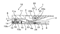
本例の給紙機構20は、図2に拡大して示すように、カットシート8の先端付近を押上げるように配置された押上げ板21と、この押上げ板21と協働してカットシート8を挟むように配置されたピックアップローラ22と、このピックアップローラ22で紙送りされたカットシート8の先端8aが当たり、その最も上部(ピックアップローラ22の側)に位置するカットシートだけを分離してプリンタアセンブリ10に送るための分離壁(分離部)23を備えている。また、押上げ板21とハウジング2との間には、押上げ板21を駆動するばね24が設置されている。
【0019】
給紙された感熱紙8に印刷を行うプリンタアセンブリ10は、紙幅方向Wに幅いっぱいに延びたラインサーマルヘッド(以降においてはサーマルヘッドあるいはヘッド)11と、このサーマルヘッド11との間に感熱紙8を挟み込み、感熱紙8の感熱面をサーマルヘッド11に押付けるプラテンローラ12と、このプラテンローラ12をサーマルヘッド11と反対側から支持する2本の支持ローラ13aおよび13bと、これらの支持ローラ13aおよび13bをさらに支持する支持プレート14を備えている。この支持プレート14は、ハウジング2に対してばね15によってサーマルヘッド11の方向に押上げられており、このためプラテンローラ12はサーマルヘッド11の印刷面11aに向けて加圧される。その結果、サーマルシート8はプラテンローラ12によって十分な圧力でサーマルヘッド11に押付けられ、印刷されて排紙口4から排出される。
【0020】
本例のプリンタ1のハウジング2には、さらに、図1に示すように、ピックアップローラ22およびプラテンローラ12を駆動するためのモータ61と、その動力伝達機構62が収納されており、さらに、モータ61の電源となるバッテリー用のスペース65も用意されている。また、本例のプリンタ1は、図示されていないが、パーソナルコンピュータあるいはPDAなどのホスト(端末)側と通信して印刷すべきデータを受信するインタフェース機能、そのデータにしたがってモータ61を制御する機能など、プリンタとして稼動するために必要な機能を全て備えている。したがって、PDAなどの携帯端末と共に本例のプリンタ1を持ち歩くだけで、所望のデータをいつでも簡単にプリントアウトすることができる。あるいは、携帯電話とドッキングさせたり、ノート型のパーソナルコンピュータのデバイスベイに収納することによりこれらの携帯端末あるいは情報処理装置と一体化し持ち歩くことが可能である。
【0021】
本例のプリンタ1は全体を薄くできるように幾つかの機構を採用している。まず、給紙機構20のピックアップローラ22は、紙幅方向に直径が2mm程度の複数の回転体22bが直径1mm程度のシャフト22aにより接続されており、これらの回転体22bの間でシャフト22aがハウジング2から延びた軸受け25により支持されている。したがって、径の細いローラであっても途中で歪むことがなく、確実に印刷用紙8をピックアップすることができる。一般的にローラの歪みを防止するには直径を大きくして強度を上げる方法が採用されるが、そのためには直径が10mm程度あるいはそれ以上が必要となる。これに対し、ピックアップローラ22のように、ローラ本体(回転体)を複数に分割し、その間でシャフトの途中を軸受け(軸サポート)により支持することにより、ローラの厚みの中でシャフトを支持する機構をアレンジでき、シャフトの曲がりを防ぐことができる。したがって、ローラ自体あるいはローラ単体で圧力をすべて受ける強度は不要であり、ローラの直径10mm程度以下、さらには5mm程度あるいはそれ以下に細くすると共に歪みを防止できる。
【0022】
しかしながら、この支持方法は、ローラが長手方向に分断されるので、プラテンローラ12に対して適用できない。すなわち、プラテンローラ12はサーマルヘッド11の長手方向の全体にわたって印刷用紙を加圧しないと、印刷できない部分あるいは印刷不良になる部分が発生してしまう。そこで、本例のプリンタアセンブリ10では、プラテンローラ12を2本の支持ローラ13aおよび13bにより支持している。
【0023】
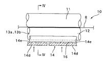
図3にプリンタアセンブリ10を構成する部品を展開した図を示してあり、図4にプリンタアセンブリ10の概略構成を横方向の断面により示してある。また、図5にプリンタアセンブリ10の概略構成を長手方向に対し側方から見た様子で示してある。2本の支持ローラ13aおよび13bは、プラテンローラ12の紙送り方向Xの前後に配置されている。このため、プラテンローラ12の中心12aとサーマルヘッド11の印刷面11aを結んだ厚み方向Tに対し、プラテンローラ12の中心12aと、各々の支持ローラ13aおよび13bの中心13cを結んだ線が傾いており、プラテンローラ12と支持ローラ13aおよび13bを重ねた構成が各々の直径の和より小さな寸法で収まるようになっている。本例のプラテンローラ12は、直径が1mmの樹脂製あるいは金属製の軸12bにシリコンゴムの被覆層12cが施された直径が2mmのローラであり、一方、支持ローラ13aおよび13bはフッ素系樹脂からなる直径が1mmの棒状のローラあるいは軸である。したがって、プラテンローラ12および支持ローラ13aおよび13bを本例のように配置すると全体が3mm以下、たとえば、厚さ2.5mm程度のスペースに配置することができる。
【0024】
支持ローラ13aおよび13bをサーマルヘッド11と反対側から支持する支持プレート14は、サーマルヘッド11の側に開いたコ字型であり、前後のコーナ14aおよび14bに支持ローラ13aおよび13bが収まるようになっている。このため、プラテンローラ12が回転すると、それに伴って2本の支持ローラ13aおよび13bは支持プレート14のコーナ14aおよび14bで回り、各々の支持ローラの中心13cは前後に動かない。このため、これらの支持ローラ13aおよび13bにより前後を支持されたプラテンローラ12もプレート14の内部で前後に動かず、所定の位置で回転する。
【0025】
さらに、支持プレート14は、給紙方向に延びたアーム部14cを備えており、このアーム部14cがばね15によって上方、すなわち、サーマルヘッド11の方向に加圧されている。このため、支持プレート14によって支持ローラ13aおよび13bがサーマルヘッド11の方向に動かされ、その結果、プラテンローラ12がサーマルヘッド11に向かって加圧される。支持プレート14は、図3に示すように、プラテンローラ12の長手方向Lに幾つかに分離されており、これら分離された部分14d毎にばね15が設けられている。本例のプラテンローラ12は、上記のように細い樹脂製あるいは金属製の軸と、ゴムの被覆によって構成されているので可撓性があり、また、支持ローラ13aおよび13bも樹脂製なので可撓性がある。したがって、幾つかに分離された支持プレート14dによってプラテンローラ12が支持ローラ13aおよび13bを介してサーマルヘッド11に押付けられる。このため、プラテンローラ12はサーマルヘッド11に沿った形状となり、サーマルヘッド11に密着する。例えば、サーマルヘッド11が若干歪み、あるいは傾いているような場合であっても、プラテンローラ12をその形状にそって変形して押付けることができる。したがって、サーマルヘッド11に印刷用紙8を所定の圧力で密着させることが可能であり、かすれなどのない品質の良い印刷を行うことができる。
【0026】
従来のプリンタにおいては、プラテンローラは印刷用紙をサーマルヘッドにむらなく押付けるために歪みが発生しないように剛性の高いものにしている。このため、ある程度の直径、たとえば10mm以上の直径で金属製の剛性の高いローラが採用される。しかしながら、本例では、非常に薄いプリンタを提供することを目的としており、プラテンローラ12の直径を小さくしている。このため、プラテンローラ12の剛性は確保することはできないので、従来のプリンタのプラテンローラとは逆に剛性の高いローラではなく、可撓性の、フレキシブルなローラを採用している。そして、可撓性のプラテンローラ12を、同様に可撓性の支持ローラ13aおよび13bを介し、それらの長手方向に適当に分割された支持プレート14によって加圧することにより可撓性のローラによってサーマルヘッド11に印刷用紙8を密着できるようにしている。このように、本例のプリンタ1では、印刷用紙をサーマルヘッドにむらなく押付けるためにプラテンローラの剛性を高めるという手法とはまったく異なり、可撓性の、フレキシブルなプラテンローラ12を用いることにより、プラテンローラ12の径を小さくし、非常に薄いプリンタ1を実現している。
【0027】
さらに、薄型のプリンタを実現するためにサーマルヘッド11自体を薄くしたり、あるいはサーマルヘッドを補強する構造を省いたりコンパクトにする必要が生ずる。この場合、サーマルヘッド11の強度を水平が保持できるほど十分に確保できない可能性があり、サーマルヘッド11が湾曲することがある。しかしながら、本例のプリンタでは、可撓性のプラテンローラ12および支持ローラ13aおよび13bを採用しているので、サーマルヘッド11の形状にプラテンローラ12および支持ローラ13aおよび13bが追従する。したがって、サーマルヘッドに多少の変形が生じることがあっても、プラテンローラ12により印刷用紙をサーマルヘッド11に密着させることができる。このため、非常に薄いプリンタであっても信頼性が高く、印刷品質の高いプリンタを提供できる。
【0028】
さらに図4および図5に示すように、プレート14の内側、すなわち、支持ローラ13aおよび13bが接触する面14eに、ローラの長手方向に断続する凹凸16を設けてある。したがって、支持ローラ13aおよび13bがプレート14と接触する面積が減り、支持ローラ13aおよび13bとプレート14との摩擦力がさらに減少する。このため、支持ローラ13aおよび13bを回転する負荷が減り、その結果、プラテンローラ12を回転駆動するための負荷が減るので、モータの動力を低減することができる。
【0029】
本例のプリンタアセンブリ(プリンタ機構)10では、プラテンローラ12としては表面がゴムで紙送りに適した摩擦係数の高いものを用いているが、これを摩擦係数の低いフッ素樹脂製の支持ローラ13aおよび13bで支持している。したがって、プラテンローラ12は支持ローラ13aおよび13bで回転支持されるので、印刷用紙8を挟んだ状態でスムーズに回転する。一方、支持ローラ13aおよび13bは、表面が支持プレート14の内面14eに当たった状態で回転するが、それらの表面の摩擦係数は低いので発生する摩擦力は小さい。したがって、プラテンローラ12の動きに大きな影響を与えることなくプラテンローラ12を支持プレート14により支持ローラ13aおよび13bを介して支持することができる。そして、本例のように支持プレート14の内面14eに凹凸16を設けることにより、支持ローラ13aおよび13bに発生する摩擦力を低減できるので、さらにスムーズにプラテンローラ12を駆動できる。
【0030】
支持ローラ13aおよび13bを、ピックアップローラ22と同様にローラ部分を長手方向に分割して軸芯をだし、それを軸受けで支持するようにすることも可能である。しかしながら、本例のプリンタアセンブリ10では、支持ローラ13aの直径が1mm程度であり、実際には軸芯そのものとなっている。したがって、さらにこれを分断して軸を形成するのは強度的に無理があり、また、加工も困難である。さらに、直径が1mm程度のスペースで軸受けを配置するのも難しい。そして、軸受けでローラを支持するということは、軸受けを支持する部材、たとえばハウジングと支持ローラの間にそれらが接触しないスペースを設ける必要がある。そして、その間隔は、支持ローラが歪んでも接触することがなく、また、製造公差を含んだ距離にする必要がある。したがって、これらをトータルすると1から2mm程度のスペースではこれを無理なく配置することが難しい。これに対し、本例のプリンタアセンブリ10においては、支持ローラ13aおよび13b自体を摩擦係数の小さなものにして、それらの表面が支持プレートに接触するようにしているので、軸受けおよび支持ローラと支持プレートとの隙間を設ける必要がない。したがって、1mm程度の空間に支持ローラと支持プレートとを無理なく配置することが可能となる。
【0031】
印刷用紙がA4程度あるいはそれ以上になると、プラテンローラ12は歪みを防止するという点はさておき、回転駆動するために強度が必要となるので10mm程度あるいはそれ以上の直径が必要となる。これに対し、支持ローラ13aおよび13bは、プラテンローラ12を回転支持できれば良いので、本例と同程度の直径のものを採用することができる。したがって、プリンタアセンブリ10の厚みを最小にするためには、本例と同様に支持ローラ13aおよび13bを支持プレート14で支持する構成が最も望ましい。もちろん、支持プレート14の形状は本例に限定されるものではなく、プラテンローラ12が支持プレート14に接触することのないように支持プレート14とプラテンローラ12の間に支持ローラ13aおよび13bを位置決めできるものであれば良い。例えば、コ字型でなくとも、支持ローラ13aおよび13bが回転する位置を決める溝が表面に形成されたものであっても良い。また、本例では2本の支持ローラでプラテンローラを支持しているが、3本以上の支持ローラを用いてももちろん良い。プラテンローラが支持プレートとダイレクトに接触するのを防止するという点では、1本の支持ローラをそれらの間に配置するという構成も取りうるが、プラテンローラ12の位置を安定して保持しにくくなるので、本例のように2本以上の支持ローラを前後に配置する構成が望ましい。
【0032】
また、本例では支持プレート14を長手方向に分断しているが、長手方向に連続した支持プレートであってもプラテンローラ12を十分な圧力でサーマルヘッド11に押付けることができる。しかしながら、上述したように、可撓性のプラテンローラおよび支持ローラを採用しているので、これらの持っているフレキシビリティーを活かし、プラテンローラ12がさらにサーマルヘッド11に密着できるようにするには、支持プレートを分割して長手方向に分散した圧力を加えることが望ましい。
【0033】
さらに、本例では支持プレート14を分割し、それぞれに対応してコイルばね15を設け圧力を加えるようにしているが、板バネ、つる巻ばねなどの他の形式のばねであっても良く、また、ばねの代わりにゴムなどの他の弾性部材を用いても良い。さらに、支持プレート14が板バネとしての機能を持った構造にすることも可能である。また、本例では、支持プレート14にばねを設けてプラテンローラ12をサーマルヘッド11の方向に加圧しているが、逆に、サーマルヘッド11の側にばねあるいはゴム板を配置して圧力を得るようにしても良い。しかしながら、プラテンローラ12および支持ローラ13aおよび13bの可撓性を活かしてサーマルヘッドに密着させるという点では、本例のように支持プレート14の側から圧力を加えることが望ましい。
【0034】
このように本例のプリンタアセンブリ10は、インクなどの消耗品を収納するスペースの不要なサーマルタイプであると共に、プラテンローラ12を支持ローラ13および支持プレート14で支持する構成を採用することにより全体を非常に薄くコンパクトに構成できる。このため、このプリンタアセンブリ10を採用することにより、非常に薄い、CDケース、さらにはフロッピーディスクケース程度の厚みのプリンタを実現することができる。そして、プラテンローラ12を回転駆動することにより印刷用紙8の供給、印刷そして排紙をスムーズに行うことが可能であり、給紙あるいは排紙のために特別な機構は不要なのでシンプルな構成で、信頼性が高く低コストのプリンタを提供できる。
【0035】
そして、薄くコンパクトなプリンタであるが、プラテンローラとサーマルヘッドとの間に十分な圧力を加え、紙幅方向に沿ってほぼ均等に印刷用紙を押付けられるので、品質の良いプリントアウトを出力可能な非常に薄型、たとえば厚みが5mm程度のプリンタを提供できる。したがって、本例のプリンタは手軽に購入でき、ポケット、ハンドバック、机に引き出しなどどこにでも収納することが可能であり、また、PDAあるいは携帯電話などの携帯端末と共に簡単に持ち運んだり、あるいはこれらの携帯端末にドッキングさせても携帯端末のサイズが大幅に変わるものでもない。したがって、いつでもどこでも手軽に使用できるプリンタである。また、カットシートにプリントアウトされた出力が得られるので、出力結果も利用しやすい。このため、使用頻度の少ないユーザにとってもストレスなく持ち運びでき、必要なときにはどこでも使用できる非常に便利なプリンタである。
【0036】
なお、上記の例ではA7サイズのカード型プリンタを例に説明しているが、このサイズに限定されないことはもちろんである。A8サイズ以下のプリンタを実現することも可能であり、さらには、本発明のプリンタアセンブリを採用することにより、A5あるいはA4サイズあるいはそれ以上の印刷用紙を使用するプリンタもさらに小型および軽量化することができる。もちろん、本例のプリントアセンブリは、ロール紙に印刷を行うプリンタにも適用することができ、プリント部分をコンパクトにすることにより、ロール紙を用いたプリンタにおいても全体をコンパクトに纏めることができる。
【0037】
【発明の効果】
以上に説明したように、本発明のプリンタアセンブリおよびプリンタにおいては、ラインサーマルヘッドと共に感熱紙を挟んで加圧するプラテンローラを摩擦係数の小さな部材からなる支持ローラを介して支持プレートによって支持するようにしている。このため、インクなどの消耗品が不用でそのスペースを必要としないためにコンパクトに実現できるのに加え、プラテンローラの径を限界まで小さくすることが可能となり、さらに全体が薄いプリンタを提供できる。そして、カードのような薄いプリンタアセンブリあるいはプリンタにおいても、歪みなく均一な圧力で感熱紙を加圧できるので、品質の高い印刷物を提供できる。このため、本発明により、超薄型のプリンタを実現するためのネックとなっていた大きな問題を解決でき、厚みが5mm程度の超薄型のプリンタを提供することができる。
【図面の簡単な説明】
【図1】本発明にかかるプリンタの平面配置を示す図である。
【図2】図1に示すプリンタのプリンタアセンブリの構造を拡大して示す断面図である。
【図3】図1に示すプリンタのプリンタアセンブリの主な構成部品を展開して示す展開斜視図である。
【図4】プリンタアセンブリの部分を拡大して示す断面図である。
【図5】プリンタアセンブリの部分を拡大して示す側面図である。
【符号の説明】
1 プリンタ
2 ハウジング
3 カットシートの収納スペース
4 排紙口
8 カットシート(印刷用紙、感熱紙、サーマルシート)
10 プリンタアセンブリ
11 ラインサーマルヘッド
12 プラテンローラ
13a、13b 支持ローラ
14 支持プレート
15 ばね
16 凹凸
20 給紙機構
21 押上げ板
22 ピックアップローラ
23 分離壁
24 ばね[0001]
BACKGROUND OF THE INVENTION
The present invention relates to a printer assembly (printing function assembly) for printing on thermal paper and a printer.
[0002]
[Prior art]
In recent years, a variety of computers have been developed and used, ranging from portable computers such as notebook computers to portable or mobile computers that fit in pockets such as PDAs. Furthermore, with the spread of the Internet, the use of computers has spread to various fields such as information provision and communication, and the user group has also expanded from specialists to general users. In the future, as the number of users expands, computers are considered to be used daily in general households. In addition, the application is also progressing in the direction of processing daily routine work at home by introducing electronic payment.
[0003]
As the number of computers or other mobile devices increases, it is likewise desired that a printout can be output whenever desired. In addition, in the case of using a computer for daily work such as electronic transactions, the amount printed out is small and the printer is often used less frequently. Therefore, one style required for future printers can be held with a portable information processing device (portable terminal) such as a PDA or a mobile phone, or can be built into the information processing device, or even in a portable terminal. It is sure that it is thin and compact so that it can be docked, and it is lightweight and low-cost. Since a printer that prints on thermal paper using a thermal head does not require ink or ribbon, the printing mechanism can be compactly integrated. In particular, a line thermal printer in which the thermal head is extended in the paper width direction (scanning direction or line direction) can be combined in a very compact manner because it does not require a mechanism for moving the thermal head in the scanning direction. It is a printer suitable for.
[0004]
[Problems to be solved by the invention]
However, in order to realize a printer having a very small thickness, for example, about 10 mm or less, a mechanism for pressing the printing paper against the thermal head is one big neck. A mechanism that feeds the thermal paper while pressing the thermal paper to the thermal head by sandwiching the thermal paper between the thermal head and the platen roller and rotating the platen roller is adopted. However, a thin printer with a thickness of 10 mm or less is used. To achieve this, it is necessary to make the diameter of the platen roller smaller than the conventionally considered size. If the platen roller has a small diameter, the contact area is insufficient. Therefore, in order to press the printing paper against the thermal head with a predetermined force, it is necessary to press the platen roller with a stronger force. However, since the strength is insufficient when the diameter of the platen roller is 10 mm or less, distortion is likely to occur when the pressing force is increased. In particular, when the diameter is about 5 mm or less, the platen roller is distorted as a whole. Therefore, the printing paper cannot be pressed against the thermal head with the force required for printing only by supporting both ends. In particular, when the line thermal head is used, the pressing force of the thermal paper varies in the paper width direction, and if the pressing force is partially insufficient, the print quality deteriorates, so that printing is impossible in practice.
[0005]
In order to prevent distortion of the platen roller, there is a method in which the platen roller is divided in the longitudinal direction to expose the shaft, and the middle of the shaft is supported by a bearing. However, in the case of a platen roller, since it is necessary to apply a uniform pressure continuous in the scanning direction, the platen roller cannot be divided in the longitudinal direction. On the other hand, it is also possible to support the entire platen roller from the side opposite to the thermal head by a member extending in the longitudinal direction. However, the surface of the platen roller uses a material having a high friction coefficient such as rubber in order to smoothly feed the paper. For this reason, in the pressurized state, there exists a problem that the frictional force between such a support member and a platen roller is too large, and motor power increases. Therefore, this method cannot be adopted.
[0006]
It is possible to arrange several sub-rollers in the longitudinal direction of the platen roller to prevent the platen roller from being distorted. However, in this mechanism, in addition to the platen roller, it is necessary to dispose a sub-roller and a bearing that supports the shaft, and to provide a clearance between the sub-roller and the housing. Therefore, a very thin printer cannot be realized.
[0007]
Under such circumstances, the inventors of the present application have eagerly developed a technique for realizing a card-type thermal printer having a thickness of about 5 mm or less. Then, the above-mentioned problems related to the platen roller were cleared, and a technology capable of realizing a very thin printer with high printing quality could be developed.
[0008]
That is, an object of the present invention is to provide a printing mechanism, that is, a printer assembly, which can collect a line thermal printer with a thickness of about 10 mm or less, and further about 5 mm or less. An object of the present invention is to provide a printer having a thickness of 10 mm or less, or about 5 mm or less.
[0009]
[Means for Solving the Problems]
For this reason, in the printer assembly of the present invention, the platen roller is supported by a thin roller (shaft) having a small friction coefficient and the surface of the support roller is supported by a plate-like member to prevent the platen roller from being distorted. In addition, more pressure can be applied. That is, the printer assembly of the present invention includes a line thermal head, a platen roller having a high friction coefficient on the surface, which sandwiches the printing paper between the line thermal head and feeds the printing paper. Support rollers with low surface friction coefficient, which are arranged before and after the paper feed direction so as to support from the opposite side of the thermal head, and the support rollers to receive the surface of these support rollers from the opposite side of the line thermal head A support plate extending along the pressure plate, and a pressurizing means for applying pressure between the support plate and the line thermal head. As the platen roller, a metal member whose surface is processed to increase the friction coefficient, or a resin having a large friction coefficient such as phenol resin can be used, but the most suitable is a rubber system having a large friction coefficient and elasticity. The surface is covered with a material. On the other hand, a resin member having a low friction coefficient, for example, a material such as nylon or polyethylene, is suitable as the support roller, and the most suitable is a fluorine type whose friction coefficient is a fraction of rubber or one digit or more smaller. A resin rod-like member is used.
[0010]
A platen roller having a high friction coefficient is received by a support roller having a low friction coefficient, and further received by a support plate extending along the longitudinal direction of the support roller, so that the platen roller continuously moves along the longitudinal direction of the platen roller. The load can be supported. Therefore, even if the platen roller itself does not have high rigidity, the platen roller can prevent distortion and apply a high pressure. At the same time, the support roller having a small friction coefficient rotates with the platen roller, and the support roller having a small friction coefficient rotates with respect to the support plate. For this reason, the frictional force when driving the platen roller can be reduced. Furthermore, since the support roller is directly received by the support plate, it is not necessary to separate the support roller from the structural member, and the line thermal head, the platen roller, and the support roller can be arranged in a very thin space. Accordingly, it is possible to realize a printer assembly that can be assembled in a very thin space and can smoothly perform paper feeding with low power.
[0011]
Further, by providing the support rollers before and after the platen roller, the positions before and after the platen roller can be defined by the support roller. Further, by arranging the platen roller and the support roller in this way, the line connecting the central axes of the platen roller and the support roller is inclined with respect to the direction in which the platen roller and the thermal head are in contact with each other. The support roller can be arranged thinner.
[0012]
For example, for a printing paper of a postcard size (A6 size), a thickness of about 5 mm or less is obtained by combining a thermal head having a thickness of 2 mm, a platen roller having a diameter of 2 mm, and a supporting roller having a diameter of 1 mm. A printer assembly can be realized. Therefore, it is very thin by combining such a thin printer assembly and a paper feed mechanism for supplying thermal paper to the printer assembly, and it can be carried, incorporated into an information processing apparatus, or a portable terminal such as a cellular phone. Therefore, it is possible to provide a compact printer suitable for being used by being docked. When the printing paper is large, the platen roller is required to have torsional strength, so that the platen roller needs a diameter of about 10 mm. However, the rigidity to the extent that the platen roller itself does not distort with respect to the pressure as in the conventional printer is not required. Therefore, a printer assembly and a printer having a thickness of about several tens of millimeters can be realized according to the present invention for A4 size printing paper.
[0013]
The present invention aims to provide such a very thin printer assembly and printer, and it is desirable that the diameter of the platen roller be as small as possible. Therefore, as described above, it is difficult to impart rigidity to the platen roller so as not to be distorted or to keep the platen roller horizontal with respect to the thermal head. In the present invention, since the support roller is supported along the longitudinal direction, a flexible and flexible platen roller is adopted, and this and the flexible support roller are reversed. By combining, the platen roller can be brought into close contact with the thermal line head. In particular, since it is difficult to reinforce the thermal line head if the whole is thin, if the thin thermal head is employed, the thermal head itself may be bent by pressure. Even in such a case, in the printer assembly of the present invention, by adopting a flexible platen roller, the platen roller can be brought into close contact with the thermal head, and the printer assembly having high reliability and printing quality. Can provide. As such a platen roller, a flexible shaft coated with rubber forming the surface is suitable, and as a support roller, a flexible shaft itself having a low friction coefficient is formed. Things are suitable.
[0014]
In the printer assembly of the present invention, since the platen roller is supported substantially continuously along the longitudinal direction, pressure may be applied from either the upper or lower direction, that is, the direction of the line thermal head, and the direction of the support plate. Pressure may be applied. Alternatively, it is of course possible to apply pressure from both sides. For example, a pressure can be applied by configuring the support plate with a highly rigid member and supporting the support plate with respect to the frame or the like by a highly elastic member such as a spring or rubber. Alternatively, the support plate itself can be an elastic member such as a leaf spring.
[0015]
Furthermore, when pressure is applied from the support plate side, the support plate can be divided along the longitudinal direction at an appropriate pitch to increase the adhesion of the platen roller to the line thermal head. In particular, it is possible to provide a printer assembly and a printer capable of increasing the adhesion of the platen roller by combining with a flexible platen roller and a support roller, and performing high-quality printing.
[0016]
It is also possible to provide the support plate with irregularities in the longitudinal direction of the support roller to further reduce the frictional force between the support roller and the support plate.
[0017]
DETAILED DESCRIPTION OF THE INVENTION
Embodiments of the present invention will be described below with reference to the drawings. FIG. 1 shows a planar configuration of a printer 1 according to the present invention. The printer 1 of this example is a portable printer housed in a
[0018]
As shown in an enlarged view in FIG. 2, the
[0019]
A
[0020]
As shown in FIG. 1, the
[0021]
The printer 1 of this example employs several mechanisms so that the whole can be thinned. First, in the
[0022]
However, this support method cannot be applied to the
[0023]
FIG. 3 shows a developed view of the components constituting the
[0024]
The
[0025]
Further, the
[0026]
In a conventional printer, the platen roller has a high rigidity so that distortion does not occur in order to press the printing paper uniformly against the thermal head. For this reason, a metal rigid roller having a certain diameter, for example, a diameter of 10 mm or more is employed. However, the purpose of this example is to provide a very thin printer, and the diameter of the
[0027]
Furthermore, in order to realize a thin printer, it is necessary to make the
[0028]
Further, as shown in FIGS. 4 and 5,
[0029]
In the printer assembly (printer mechanism) 10 of this example, the
[0030]
Similarly to the
[0031]
When the printing paper is about A4 or more, the
[0032]
Further, in this example, the
[0033]
Further, in this example, the
[0034]
As described above, the
[0035]
Although it is a thin and compact printer, it can apply a sufficient pressure between the platen roller and the thermal head and press the printing paper almost evenly along the paper width direction. In addition, a printer having a thin thickness, for example, a thickness of about 5 mm can be provided. Therefore, the printer of this example can be easily purchased and can be stored anywhere such as pockets, handbags, drawers, etc., and can be easily carried with a portable terminal such as a PDA or a mobile phone, or these portables. Even when docked on a device, the size of the mobile device does not change significantly. Therefore, the printer can be easily used anytime and anywhere. Moreover, since the output printed on the cut sheet is obtained, the output result is easy to use. For this reason, it is a very convenient printer that can be carried without stress for users with low frequency of use and can be used anywhere when necessary.
[0036]
In the above example, an A7 size card type printer is described as an example, but it is needless to say that the size is not limited to this. It is possible to realize a printer of A8 size or smaller, and further, by adopting the printer assembly of the present invention, a printer using printing paper of A5 or A4 size or larger can be further reduced in size and weight. Can do. Of course, the print assembly of this example can also be applied to a printer that prints on roll paper, and by making the print portion compact, the entire printer can also be compactly combined even in a printer using roll paper.
[0037]
【The invention's effect】
As described above, in the printer assembly and printer of the present invention, the platen roller that presses the thermal paper together with the line thermal head is supported by the support plate via the support roller made of a member having a small friction coefficient. ing. This eliminates the need for consumables such as ink and does not require space, so that it can be realized in a compact manner, and the diameter of the platen roller can be reduced to the limit, and a printer with a thinner overall can be provided. Further, even in a thin printer assembly such as a card or a printer, the thermal paper can be pressed with a uniform pressure without distortion, so that a high-quality printed matter can be provided. For this reason, the present invention can solve a major problem that has been a bottleneck for realizing an ultra-thin printer, and can provide an ultra-thin printer having a thickness of about 5 mm.
[Brief description of the drawings]
FIG. 1 is a diagram showing a planar arrangement of a printer according to the present invention.
2 is an enlarged cross-sectional view showing a structure of a printer assembly of the printer shown in FIG. 1. FIG.
3 is a developed perspective view showing the main components of the printer assembly of the printer shown in FIG.
FIG. 4 is an enlarged cross-sectional view of a portion of the printer assembly.
FIG. 5 is an enlarged side view showing a part of the printer assembly.
[Explanation of symbols]
1 Printer
2 Housing
3 Storage space for cut sheets
4 Paper exit
8 Cut sheet (printing paper, thermal paper, thermal sheet)
10 Printer assembly
11 Line thermal head
12 Platen roller
13a, 13b Support roller
14 Support plate
15 Spring
16 Concavity and convexity
20 Paper feed mechanism
21 Push-up plate
22 Pickup roller
23 Separation wall
24 Spring
Claims (10)
このラインサーマルヘッドとの間に印刷用紙を挟み、該印刷用紙を紙送りする、表面の摩擦係数が高いプラテンローラと、
このプラテンローラを前記ラインサーマルヘッドの反対側から支持するように紙送り方向の前後に配置された、表面の摩擦係数が低い、複数の支持ローラと、
これらの複数の支持ローラの表面に接触し、前記複数の支持ローラを前記ラインサーマルヘッドの反対側から受けるように前記複数の支持ローラに沿って延びた支持プレートと、
この支持プレートとラインサーマルヘッドの間に圧力を加える加圧手段とを有し、前記支持プレートの断面は、前記ラインサーマルヘッドの側に開いたコ字型であり、前後のコーナに前記複数の支持ローラがそれぞれ収まっている、プリンタアセンブリ。Line thermal head,
A platen roller having a high surface friction coefficient, sandwiching the printing paper between the line thermal head and feeding the printing paper,
A plurality of support rollers disposed on the front and back of the paper feed direction so as to support the platen roller from the opposite side of the line thermal head, and having a low surface friction coefficient;
A support plate that contacts the surfaces of the plurality of support rollers and extends along the plurality of support rollers so as to receive the plurality of support rollers from the opposite side of the line thermal head;
Possess a pressure means for applying pressure between the support plate and the line thermal head, the cross section of the support plate is a U-shaped open to the side of the line thermal head, the plurality of before and after the corner A printer assembly that contains support rollers .
前記加圧手段はこの支持プレートを加圧する、プリンタアセンブリ。In Claim 1, the support plate is a highly rigid member,
The printer assembly, wherein the pressing means pressurizes the support plate.
このラインサーマルヘッドとの間に印刷用紙を挟み、該印刷用紙を紙送りする、表面の摩擦係数が高いプラテンローラと、
このプラテンローラを前記ラインサーマルヘッドの反対側から支持するように紙送り方向の前後に配置された、表面の摩擦係数が低い、複数の支持ローラと、
これらの複数の支持ローラの表面に接触し、前記複数の支持ローラを前記ラインサーマルヘッドの反対側から受けるように前記複数の支持ローラに沿って延びた支持プレートであって、前記プラテンローラをラインサーマルヘッドに向かって加圧するための支持プレートとを有し、前記支持プレートの断面は、前記ラインサーマルヘッドの側に開いたコ字型であり、前後のコーナに前記複数の支持ローラがそれぞれ収まっている、プリンタアセンブリ。Line thermal head,
A platen roller having a high surface friction coefficient, sandwiching the printing paper between the line thermal head and feeding the printing paper,
A plurality of support rollers disposed on the front and back of the paper feed direction so as to support the platen roller from the opposite side of the line thermal head, and having a low surface friction coefficient;
A support plate that contacts the surfaces of the plurality of support rollers and extends along the plurality of support rollers so as to receive the plurality of support rollers from the opposite side of the line thermal head; possess a support plate for pressing against the thermal head, the cross section of the support plate is a U-shaped open to the side of the line thermal head, seated plurality of supporting rollers, each before and after the corner The printer assembly.
Priority Applications (3)
| Application Number | Priority Date | Filing Date | Title |
|---|---|---|---|
| JP26736699A JP4169440B2 (en) | 1999-09-21 | 1999-09-21 | Printer assembly and printer |
| EP00120421A EP1086817A3 (en) | 1999-09-21 | 2000-09-18 | Printer assembly and printer |
| US10/072,944 US6626597B2 (en) | 1999-09-21 | 2002-02-12 | Printer assembly and printer |
Applications Claiming Priority (1)
| Application Number | Priority Date | Filing Date | Title |
|---|---|---|---|
| JP26736699A JP4169440B2 (en) | 1999-09-21 | 1999-09-21 | Printer assembly and printer |
Publications (3)
| Publication Number | Publication Date |
|---|---|
| JP2001088376A JP2001088376A (en) | 2001-04-03 |
| JP2001088376A5 JP2001088376A5 (en) | 2006-11-16 |
| JP4169440B2 true JP4169440B2 (en) | 2008-10-22 |
Family
ID=17443840
Family Applications (1)
| Application Number | Title | Priority Date | Filing Date |
|---|---|---|---|
| JP26736699A Expired - Fee Related JP4169440B2 (en) | 1999-09-21 | 1999-09-21 | Printer assembly and printer |
Country Status (2)
| Country | Link |
|---|---|
| EP (1) | EP1086817A3 (en) |
| JP (1) | JP4169440B2 (en) |
Family Cites Families (3)
| Publication number | Priority date | Publication date | Assignee | Title |
|---|---|---|---|---|
| JPS57150586A (en) * | 1981-03-13 | 1982-09-17 | Fuji Xerox Co Ltd | Heat sensitive recorder |
| JPS61290072A (en) * | 1985-06-19 | 1986-12-20 | Hitachi Ltd | Thermal printer |
| JP2914202B2 (en) * | 1995-01-11 | 1999-06-28 | 日本電気株式会社 | Thermal head pressure roller device |
-
1999
- 1999-09-21 JP JP26736699A patent/JP4169440B2/en not_active Expired - Fee Related
-
2000
- 2000-09-18 EP EP00120421A patent/EP1086817A3/en not_active Withdrawn
Also Published As
| Publication number | Publication date |
|---|---|
| JP2001088376A (en) | 2001-04-03 |
| EP1086817A3 (en) | 2001-05-16 |
| EP1086817A2 (en) | 2001-03-28 |
Similar Documents
| Publication | Publication Date | Title |
|---|---|---|
| US6626597B2 (en) | Printer assembly and printer | |
| US6121990A (en) | Printing apparatus and cartridge | |
| JPS6044384A (en) | Ribbon-cartridge with ink feeding mechanism | |
| JP6341753B2 (en) | Transfer device | |
| JP4169440B2 (en) | Printer assembly and printer | |
| CN208164550U (en) | Thermal printer and portable terminal | |
| JPH10272808A (en) | Portable printer | |
| CN1115853C (en) | Facsimile apparatus and roll-like sheet holder | |
| US5146238A (en) | Line-type thermal printing apparatus for printing on a sheet having different thicknesses | |
| JP2001096823A (en) | Printer assembly and printer | |
| JP4895195B2 (en) | Laminating equipment | |
| JP4683786B2 (en) | Printer | |
| JP3156322U (en) | Card cutting device | |
| JP4384688B2 (en) | Card printer | |
| CN215552003U (en) | Novel digital printing machine | |
| JP2000225736A (en) | Printer | |
| CN218505485U (en) | Card making equipment | |
| JP2012223923A (en) | Printing device | |
| US20040240923A1 (en) | Thermal printer | |
| JP2871637B2 (en) | Roll paper holder, terminal device and label printer | |
| JP3313799B2 (en) | Feeding device | |
| JPH0789164A (en) | Sheet feed device | |
| JP3211842B2 (en) | Printer | |
| CN115848025A (en) | Printing device | |
| JP2527654Y2 (en) | Document reader |
Legal Events
| Date | Code | Title | Description |
|---|---|---|---|
| A521 | Written amendment |
Free format text: JAPANESE INTERMEDIATE CODE: A523 Effective date: 20060920 |
|
| A621 | Written request for application examination |
Free format text: JAPANESE INTERMEDIATE CODE: A621 Effective date: 20060920 |
|
| A977 | Report on retrieval |
Free format text: JAPANESE INTERMEDIATE CODE: A971007 Effective date: 20080502 |
|
| A131 | Notification of reasons for refusal |
Free format text: JAPANESE INTERMEDIATE CODE: A131 Effective date: 20080509 |
|
| A521 | Written amendment |
Free format text: JAPANESE INTERMEDIATE CODE: A523 Effective date: 20080707 |
|
| TRDD | Decision of grant or rejection written | ||
| A01 | Written decision to grant a patent or to grant a registration (utility model) |
Free format text: JAPANESE INTERMEDIATE CODE: A01 Effective date: 20080729 |
|
| A01 | Written decision to grant a patent or to grant a registration (utility model) |
Free format text: JAPANESE INTERMEDIATE CODE: A01 |
|
| A61 | First payment of annual fees (during grant procedure) |
Free format text: JAPANESE INTERMEDIATE CODE: A61 Effective date: 20080805 |
|
| FPAY | Renewal fee payment (event date is renewal date of database) |
Free format text: PAYMENT UNTIL: 20110815 Year of fee payment: 3 |
|
| R150 | Certificate of patent or registration of utility model |
Free format text: JAPANESE INTERMEDIATE CODE: R150 |
|
| FPAY | Renewal fee payment (event date is renewal date of database) |
Free format text: PAYMENT UNTIL: 20110815 Year of fee payment: 3 |
|
| FPAY | Renewal fee payment (event date is renewal date of database) |
Free format text: PAYMENT UNTIL: 20140815 Year of fee payment: 6 |
|
| LAPS | Cancellation because of no payment of annual fees |