JP4168059B2 - PON system and station side device - Google Patents
PON system and station side device Download PDFInfo
- Publication number
- JP4168059B2 JP4168059B2 JP2006107790A JP2006107790A JP4168059B2 JP 4168059 B2 JP4168059 B2 JP 4168059B2 JP 2006107790 A JP2006107790 A JP 2006107790A JP 2006107790 A JP2006107790 A JP 2006107790A JP 4168059 B2 JP4168059 B2 JP 4168059B2
- Authority
- JP
- Japan
- Prior art keywords
- congestion
- frame
- bandwidth
- output port
- subscriber connection
- Prior art date
- Legal status (The legal status is an assumption and is not a legal conclusion. Google has not performed a legal analysis and makes no representation as to the accuracy of the status listed.)
- Expired - Fee Related
Links
Images


Classifications
-
- H—ELECTRICITY
- H04—ELECTRIC COMMUNICATION TECHNIQUE
- H04Q—SELECTING
- H04Q11/00—Selecting arrangements for multiplex systems
- H04Q11/0001—Selecting arrangements for multiplex systems using optical switching
- H04Q11/0062—Network aspects
- H04Q11/0067—Provisions for optical access or distribution networks, e.g. Gigabit Ethernet Passive Optical Network (GE-PON), ATM-based Passive Optical Network (A-PON), PON-Ring
-
- H—ELECTRICITY
- H04—ELECTRIC COMMUNICATION TECHNIQUE
- H04L—TRANSMISSION OF DIGITAL INFORMATION, e.g. TELEGRAPHIC COMMUNICATION
- H04L47/00—Traffic control in data switching networks
- H04L47/10—Flow control; Congestion control
- H04L47/11—Identifying congestion
- H04L47/115—Identifying congestion using a dedicated packet
-
- H—ELECTRICITY
- H04—ELECTRIC COMMUNICATION TECHNIQUE
- H04L—TRANSMISSION OF DIGITAL INFORMATION, e.g. TELEGRAPHIC COMMUNICATION
- H04L47/00—Traffic control in data switching networks
- H04L47/10—Flow control; Congestion control
- H04L47/26—Flow control; Congestion control using explicit feedback to the source, e.g. choke packets
- H04L47/263—Rate modification at the source after receiving feedback
-
- H—ELECTRICITY
- H04—ELECTRIC COMMUNICATION TECHNIQUE
- H04Q—SELECTING
- H04Q11/00—Selecting arrangements for multiplex systems
- H04Q11/0001—Selecting arrangements for multiplex systems using optical switching
- H04Q11/0062—Network aspects
- H04Q11/0071—Provisions for the electrical-optical layer interface
-
- H—ELECTRICITY
- H04—ELECTRIC COMMUNICATION TECHNIQUE
- H04Q—SELECTING
- H04Q11/00—Selecting arrangements for multiplex systems
- H04Q11/0001—Selecting arrangements for multiplex systems using optical switching
- H04Q11/0062—Network aspects
- H04Q2011/0064—Arbitration, scheduling or medium access control aspects
Description
本発明は、受動光網(PON:Passive Optical Network)によって接続された局側装置(OLT:Optical Line Terminal)と複数の加入者側装置(ONU:Optical Network Unit)とからなるPONシステムに関し、更に詳しくは、OLTと接続されたフレーム転送装置の何れかの出力ポートが輻輳状態となった場合のPON区間の帯域制御に関する。 The present invention relates to a PON system including a station side device (OLT: Optical Line Terminal) and a plurality of subscriber side devices (ONU: Optical Network Unit) connected by a passive optical network (PON), Specifically, the present invention relates to bandwidth control in the PON section when any output port of the frame transfer apparatus connected to the OLT is congested.
インターネットへの接続サービスを提供するキャリア網は、複数の加入者を直接収容するアクセス網と、複数のアクセス網を束ねる中継網(以下、メトロ網と言う)とから構成されている。また、アクセス網の1つの形態として、受動光網PONがある。
PONは、OLTと複数のONUを光信号の分岐機能を備えた光ファイバ網で接続し、各ONUが、OLTから通知されたアクセス権(データ送信時間帯)情報に従って、時分割でOLTにデータを伝送するネットワークシステムである。PONは、OLTに接続された光ファイバを光スプリッタ(光カプラ)で複数の支線光ファイバに分岐し、ユーザ宅に配置されたONUを各支線光ファイバに接続することによって、光スプリッタとOLTとの間の光ファイバ区間を複数のONUで共用できるため、光ファイバの敷設費用が安くて済み、ONUを介して多数のユーザ端末を収容できるという利点がある。
A carrier network that provides a connection service to the Internet is composed of an access network that directly accommodates a plurality of subscribers and a relay network that bundles the plurality of access networks (hereinafter referred to as a metro network). One form of access network is a passive optical network PON.
The PON connects the OLT and a plurality of ONUs with an optical fiber network having an optical signal branching function, and each ONU transmits data to the OLT in a time-sharing manner according to access right (data transmission time zone) information notified from the OLT. Is a network system that transmits The PON branches an optical fiber connected to the OLT into a plurality of branch optical fibers by an optical splitter (optical coupler), and connects the ONUs arranged at the user's home to the respective branch optical fibers, so that the optical splitter, the OLT, Since the optical fiber section between the two can be shared by a plurality of ONUs, the installation cost of the optical fiber can be reduced, and there is an advantage that a large number of user terminals can be accommodated via the ONU.
PONシステムのOLTは、例えば、ゲートウェイ(GW)を介して、メトロ網に接続される。GWは、複数のOLTを収容し、各OLTとメトロ網との間で可変長フレームをヘッダに従って転送するフレーム転送装置である。メトロ網は、OLTを収容するGW以外に、例えば、ISP網を収容するGWを含む。従って、ONUに接続された各ユーザ端末は、OLT、GW、ISP網を介して、インターネットをアクセスできる。 The OLT of the PON system is connected to the metro network via, for example, a gateway (GW). The GW is a frame transfer apparatus that accommodates a plurality of OLTs and transfers variable length frames according to the header between each OLT and the metro network. The metro network includes, for example, a GW that accommodates an ISP network in addition to the GW that accommodates the OLT. Therefore, each user terminal connected to the ONU can access the Internet via the OLT, GW, and ISP networks.
PONには、光ファイバ区間(PON区間)で固定長のATMセルによって情報を伝送するB−PON(Broadband PON)、ギガビットクラスの高速データ転送を可能にするG−PON(Gigabit PON)、イーサネット(登録商標)サービスに適したGE−PON(Giga-Ethernet PON)がある。
可変長フレームの転送が可能なG−PONでは、OLTは、PON区間に特有のフレームであるGTC(G-PON Transmission Convergence)ダウンストリームフレームを生成し、各ONU宛のパケットデータを含むGEM(G-PON Encapsulation Mode)フレームをGTCダウンストリームフレームのペイロードにマッピングする。上記GTCダウンストリームフレームは、光スプリッタ(光カプラ)によって複数の支線光ファイバにブロードキャストされる。各ONUは、GTCペイロードから抽出されたGEMフレームのヘッダ部が示す宛先ONU識別情報(ONUポートID)をチェックして、自分宛のパケットデータを選択的に受信して、ユーザ端末に転送する。
The PON includes B-PON (Broadband PON) that transmits information using fixed-length ATM cells in an optical fiber section (PON section), G-PON (Gigabit PON) that enables high-speed data transfer in the Gigabit class, Ethernet ( There is a GE-PON (Giga-Ethernet PON) suitable for registered service.
In G-PON capable of transferring variable-length frames, the OLT generates a GTC (G-PON Transmission Convergence) downstream frame, which is a frame specific to the PON section, and includes GEM (G -PON Encapsulation Mode) maps the frame to the payload of the GTC downstream frame. The GTC downstream frame is broadcast to a plurality of branch optical fibers by an optical splitter (optical coupler). Each ONU checks the destination ONU identification information (ONU port ID) indicated by the header part of the GEM frame extracted from the GTC payload, selectively receives the packet data addressed to itself, and transfers it to the user terminal.
PONのOLTは、各ONUにおける送信待ちデータの蓄積量(送信キュー長)に応じて、ONU毎にデータ送信時間帯(タイムスロット)を割り当てる動的帯域割当て(DBA:Dynamic Bandwidth Allocation)機能を備えている。DBAでは、所定周期ΔT内で、1つまたは複数のONUにタイムスロットを割当てる。従って、1つのONUに割当て可能な最大のタイムスロットはΔTとなり、光ファイバ回線の帯域をBとすると、ONUに割当て可能な最大帯域B(limit)はΔT×Bとなる。OLTのDBA機能は、ONUにおける送信待ちデータ量に応じて、周期ΔT内で割当て可能な最大帯域B(limit)を複数のONUに分配する。 The PON OLT has a Dynamic Bandwidth Allocation (DBA) function that allocates a data transmission time zone (time slot) for each ONU according to the amount of transmission waiting data (transmission queue length) in each ONU. ing. In DBA, time slots are allocated to one or a plurality of ONUs within a predetermined period ΔT. Therefore, the maximum time slot that can be allocated to one ONU is ΔT, and if the bandwidth of the optical fiber line is B, the maximum bandwidth B (limit) that can be allocated to the ONU is ΔT × B. The DBA function of the OLT distributes the maximum bandwidth B (limit) that can be allocated within the period ΔT to a plurality of ONUs according to the amount of data waiting for transmission in the ONU.
G−PONでは、各タイムスロットは、送信開始時刻と送信終了時刻によって指定される。OLTは、ONU識別情報とタイムスロットとを示すONU別の帯域制御情報をGTCダウンストリームフレームのヘッダ部に設定して、各ONUに通知する。PONでは、支線光ファイバ区間の長さが不均一になるため、ONUからOLTに向かう上りフレームの伝送遅延時間がONU毎に異なる。そのため、OLTは、ONU毎の伝送遅延時間を測定しておき、各ONUに予め等価遅延時間を通知している、各ONUは、OLTからタイムスロットの割り当てを受けると、指定された送信開始時刻を上記等価遅延時間で補正して、適切なタイミングでデータ送信を開始する機能を備えている。 In G-PON, each time slot is designated by a transmission start time and a transmission end time. The OLT sets ONU-specific bandwidth control information indicating ONU identification information and time slots in the header portion of the GTC downstream frame, and notifies each ONU. In PON, since the length of the branch optical fiber section is non-uniform, the transmission delay time of the upstream frame from the ONU to the OLT is different for each ONU. Therefore, the OLT measures the transmission delay time for each ONU and notifies each ONU in advance of the equivalent delay time. When each ONU receives a time slot assignment from the OLT, the specified transmission start time Is corrected with the equivalent delay time, and a function of starting data transmission at an appropriate timing is provided.
OLTは、ONUから受信した上りフレームをGWに転送する。この場合、OLTの送信バッファで容量不足が発生すると、フレームが廃棄される可能性がある。このようなフレーム廃棄を回避するため、例えば、特開2004−159203号公報(特許文献1)には、OLT内のバッファで蓄積データ量が所定の閾値を超えた時、PON区間のアクセス権を調整し、そのOLTに収容されている全てONUからの送信データ量を制限するパケット転送装置が提案されている。以下の説明では、蓄積データ量が所定の閾値を超え、そのまま放置すればフレーム廃棄が発生するような状態を輻輳と定義する。 The OLT transfers the upstream frame received from the ONU to the GW. In this case, if a capacity shortage occurs in the OLT transmission buffer, the frame may be discarded. In order to avoid such frame discard, for example, Japanese Patent Application Laid-Open No. 2004-159203 (Patent Document 1) states that the access right of the PON section is given when the accumulated data amount exceeds a predetermined threshold in the buffer in the OLT. A packet transfer apparatus that adjusts and limits the amount of transmission data from all ONUs accommodated in the OLT has been proposed. In the following description, a state in which the amount of stored data exceeds a predetermined threshold and frame discarding occurs if left as it is is defined as congestion.
通信ネットワーク分野では、通信フレームの廃棄を防止する技術として、輻輳が発生したノード装置からデータ送信元装置に輻輳の発生を通知し、データ送信元装置にデータ送信を停止、または送信データ量を調整させるバックプレッシャ(BP)が知られている。例えば、特開2004−153505公報(特許文献2)には、IEEE(Institute of Electrical and Electronic Engineers)802.3準拠のポーズフレームを用いて輻輳を制御するデータフレーム伝送システムが提案されている。上記特許文献2では、輻輳が発生すると、データフレーム伝送装置が、データ送信元となる伝送装置にポーズフレームを送信する。ポーズフレームを受信した伝送装置は、ポーズフレームのペイロード部分で指定された期間、データフレーム伝送を停止または帯域を制限する。
In the communication network field, as a technology to prevent the discarding of communication frames, the node device where congestion has occurred reports the occurrence of congestion to the data transmission source device and stops data transmission to the data transmission source device or adjusts the amount of transmission data A back pressure (BP) is known. For example, Japanese Patent Laid-Open No. 2004-153505 (Patent Document 2) proposes a data frame transmission system that controls congestion using a pause frame conforming to IEEE (Institute of Electrical and Electronic Engineers) 802.3. In
インターネット接続サービスをキャリア網では、加入者端末とメトロ網との間に、例えば、VLAN(Virtual Local Area Network)やMPLS(Multi-Protocol Label Switching)などの通信プロトコルによって設定された論理パスが利用される。論理パスを利用すると、特定の加入者端末から送信されたユーザフレームを予め決められた経路に沿って転送できる。しかしながら、論理パスを設定すると、データ量の多い論理パスが集中したゲートウェイ(GW)において輻輳が発生し、状況によっては、転送フレームの一部が廃棄される可能性がある。 In an Internet connection service carrier network, a logical path set by a communication protocol such as VLAN (Virtual Local Area Network) or MPLS (Multi-Protocol Label Switching) is used between a subscriber terminal and a metro network. The When the logical path is used, a user frame transmitted from a specific subscriber terminal can be transferred along a predetermined route. However, when a logical path is set, congestion occurs in the gateway (GW) in which logical paths with a large amount of data are concentrated, and depending on the situation, a part of the transfer frame may be discarded.
複数のPONを収容したGWでは、特定の出力ポートが輻輳状態になった時、各PONのOLTにバックプレッシャをかけることによって、輻輳ポートでのフレーム廃棄を回避することができる。すなわち、輻輳が発生した時、特許文献1のようにPON区間のアクセス権調整機能を備えたOLTに対して、GWからバックプレッシャをかければ、OLTからGWに向かうデータ量を削減できる。また、特許文献2の技術を応用すれば、OLTは、ポーズフレームで指定された期間、PON区間のアクセス権を調整することになる。
In a GW accommodating a plurality of PONs, when a specific output port is congested, frame discard at the congestion port can be avoided by applying back pressure to the OLT of each PON. That is, when congestion occurs, if the back pressure is applied from the GW to the OLT provided with the access right adjustment function in the PON section as in
然るに、OLTを収容しているGWは、複数の入出力ポート(回線インタフェース)を備えているため、特定の出力ポートに送信データが集中しても、多くの場合、その他の出力ポートではバッファ容量に余裕がある。以下の説明では、転送データが集中して、出力バッファ容量が不足したポートを「輻輳ポート」、出力バッファ容量に余裕があるポートを「通常ポート」と呼ぶ。また、輻輳ポートを通過する論理パスを「輻輳ポートパス」、通常ポートを通過する論理パスを「通常ポートパス」と呼ぶことにする。 However, since the GW accommodating the OLT has a plurality of input / output ports (line interfaces), even if transmission data is concentrated on a specific output port, in many cases, the buffer capacity of the other output ports Can afford. In the following description, a port in which transfer data is concentrated and an output buffer capacity is insufficient is referred to as a “congestion port”, and a port having a sufficient output buffer capacity is referred to as a “normal port”. Further, a logical path passing through the congestion port is referred to as a “congestion port path”, and a logical path passing through the normal port is referred to as a “normal port path”.
このように、GWに輻輳ポートと通常ポートとが共存した状態で、特許文献1の輻輳制御を適用すると、GWに接続された全てのOLTが、それぞれに接続されている全てのONUからの送信データ量を抑制することになる。従って、各OLTからのデータ送信の抑制によって、GWでの輻輳が解消されたとしても、輻輳制御期間中は、通常ポートパスを利用している加入者(ONU)の帯域までもが制限され、アクセス網全体のスループットが低下するという問題がある。
また、特許文献1の輻輳制御によれば、輻輳制御期間中は、輻輳ポートパスの利用者と通常ポートパスの利用者を区別することなく、各ONUの割当て帯域が削減されるため、出力帯域の制限によってONUの送信バッファが溢れた場合、通常ポートパスの利用者にもフレーム廃棄の被害が及ぶという問題がある。
In this way, when the congestion control of
Further, according to the congestion control of
本発明の目的は、OLTと接続されたフレーム転送装置(GW)側で輻輳が発生した時、PON区間の上り帯域を有効に利用した輻輳制御が可能なPONシステムおよび帯域制御方法を提供することにある。
本発明の他の目的は、OLTと接続されたフレーム転送装置(GW)側で輻輳が発生した時、GWの通常ポートを利用しているONUの割当て帯域を低下させることなく、輻輳制御できるPONシステムおよび帯域制御方法を提供することにある。
An object of the present invention is to provide a PON system and a bandwidth control method capable of performing congestion control that effectively uses the upstream bandwidth of a PON section when congestion occurs on the frame transfer apparatus (GW) side connected to the OLT. It is in.
Another object of the present invention is a PON capable of controlling congestion without reducing the allocated bandwidth of the ONU using the normal port of the GW when congestion occurs on the frame transfer device (GW) connected to the OLT. A system and a bandwidth control method are provided.
上記目的を達成するため、本発明によるPONシステムは、受動光網PONで複数の加入者側装置(ONU)に接続され、通信回線を介してフレーム転送装置(GW)に接続された局側装置(OLT)が、GWから輻輳状態となった出力ポート番号を示す輻輳発生通知を受信した時、上記輻輳出力ポート番号をもつGW出力回線を利用中のONUの識別子を特定し、PON区間の帯域制御をONUへの通常の帯域割当てモードから、上記特定ONU識別子をもつONUには現在帯域よりも少ない輻輳時許容帯域を割り当て、他のONUには各々の送信キュー長に応じた帯域を割り当てる帯域抑制モードに切替えることを特徴とする。 In order to achieve the above object, a PON system according to the present invention is connected to a plurality of subscriber units (ONUs) via a passive optical network PON, and is connected to a frame transfer unit (GW) via a communication line. When (OLT) receives a congestion occurrence notification indicating an output port number in a congested state from the GW, the identifier of the ONU that is using the GW output line having the congestion output port number is specified, and the bandwidth of the PON section From the normal bandwidth allocation mode to the ONU, a bandwidth in which an allowable bandwidth at the time of congestion smaller than the current bandwidth is allocated to the ONU having the specific ONU identifier, and a bandwidth according to each transmission queue length is allocated to the other ONUs It is characterized by switching to the suppression mode.
更に詳述すると、本発明のPONシステムでは、OLTが、GWの出力ポート番号と、該出力ポート番号で特定されるGW出力回線を利用するONUの識別子との対応関係を記憶した輻輳制御テーブルと、各ONUから上りPONフレームで通知された送信キュー長を記憶しておき、上記各ONUに対して、PON区間の次の上りフレーム送信帯域として、各々の送信キュー長に応じて配分された帯域を動的に割当てるOLT制御部と、上記OLT制御部によって割り当てられたフレーム送信帯域に基いて、ONU毎の上りフレーム送信帯域を示す帯域制御情報を含む下りPONフレームを生成する下りフレーム生成部とを備え、上記OLT制御部が、上記GWから輻輳状態となった出力ポート番号を示す輻輳発生通知を受信した時、上記帯域制御テーブルから上記輻輳出力ポート番号と対応するONU識別子を特定し、PON区間の帯域制御をONUへの通常の帯域割当てモードから、上記特定ONU識別子をもつONUには現在帯域よりも少ない輻輳時許容帯域を割り当て、他のONUには各々の送信キュー長に応じた帯域を割り当てる帯域抑制モードに切替えることを特徴とする。 More specifically, in the PON system of the present invention, the OLT has a congestion control table that stores the correspondence between the output port number of the GW and the identifier of the ONU that uses the GW output line specified by the output port number. The transmission queue length notified from each ONU in the upstream PON frame is stored, and the bandwidth allocated according to each transmission queue length as the next upstream frame transmission bandwidth of the PON section to each ONU. An OLT control unit that dynamically allocates a downstream frame generation unit that generates a downstream PON frame including bandwidth control information indicating an upstream frame transmission bandwidth for each ONU, based on the frame transmission band allocated by the OLT control unit; When the OLT control unit receives a congestion occurrence notification indicating an output port number in a congested state from the GW, the band The ONU identifier corresponding to the congestion output port number is specified from the control table, and the bandwidth control of the PON section is permitted from the normal bandwidth allocation mode to the ONU. A bandwidth is allocated, and the other ONUs are switched to a bandwidth suppression mode in which a bandwidth corresponding to each transmission queue length is allocated.
本発明の1実施例では、上記OLT制御部が、上記各ONUの識別子と対応して、ONUから通知された送信キュー長と、該送信キュー長に応じて所定周期で算出された割当て帯域と、輻輳フラグとを記憶する帯域制御テーブルを備え、上記GWから輻輳発生通知を受信した時、上記帯域制御テーブルで特定されたONU識別子と対応する輻輳フラグを輻輳表示状態に切り替え、上記帯域抑制モードの帯域制御において、輻輳フラグが正常状態のONUには、各々の送信キュー長に応じた帯域を割り当て、輻輳フラグが輻輳表示状態のONUには、輻輳時許容帯域を割り当てるようにしたことを特徴とする。 In one embodiment of the present invention, the OLT control unit corresponds to the identifier of each ONU, the transmission queue length notified from the ONU, and the allocated bandwidth calculated in a predetermined cycle according to the transmission queue length. A bandwidth control table for storing a congestion flag, and when a congestion occurrence notification is received from the GW, the congestion flag corresponding to the ONU identifier specified in the bandwidth control table is switched to a congestion display state, and the bandwidth suppression mode is In the bandwidth control, a bandwidth corresponding to each transmission queue length is assigned to an ONU whose congestion flag is in a normal state, and an allowable bandwidth at the time of congestion is assigned to an ONU whose congestion flag is in a congestion display state. And
また、本発明の1実施例では、上記下りフレーム生成部が、上記帯域制御テーブルが示す輻輳フラグの状態に応じてONU毎の帯域制御情報を生成し、各下りPONフレームで、輻輳フラグが正常状態のONUには、上記送信キュー長に応じた帯域を通知し、輻輳フラグが輻輳表示状態のONUには、上記輻輳時許容帯域を通知することを特徴とする。
尚、上記OLT制御部は、GWから輻輳状態が解消した出力ポート番号を示す輻輳解除通知を受信した時、上記帯域制御テーブルから上記輻輳解消出力ポート番号と対応するONU識別子を特定しておき、所定のタイミングで、上記帯域制御テーブルの上記特定ONU識別子と対応する輻輳フラグを正常状態に切り替える。
In one embodiment of the present invention, the downlink frame generation unit generates bandwidth control information for each ONU according to the state of the congestion flag indicated by the bandwidth control table, and the congestion flag is normal in each downlink PON frame. The ONU in the state is notified of the bandwidth according to the transmission queue length, and the ONU in which the congestion flag is in the congestion display state is notified of the allowable bandwidth at the time of congestion.
When the OLT control unit receives a congestion release notification indicating the output port number from which the congestion state has been eliminated from the GW, the OLT control unit specifies the ONU identifier corresponding to the congestion elimination output port number from the bandwidth control table, At a predetermined timing, the congestion flag corresponding to the specific ONU identifier in the bandwidth control table is switched to a normal state.
本発明によれば、OLTが接続されたGWの特定の出力ポートが輻輳状態となった時、OLT側で、上記輻輳出力ポートに向かう通信フレームを送信する特定ONUの帯域を選択的に削減し、それによって生じるPON区間の余剰帯域を他のONUに配分することが可能となるため、システム全体のスループットを低下させることなく、GWの輻輳状態を解消することができる。 According to the present invention, when a specific output port of a GW to which an OLT is connected becomes congested, the bandwidth of a specific ONU that transmits a communication frame toward the congestion output port is selectively reduced on the OLT side. Since the surplus bandwidth of the PON section generated thereby can be distributed to other ONUs, the congestion state of the GW can be eliminated without reducing the throughput of the entire system.
以下、本発明の実施形態について図面を参照して説明する。 Embodiments of the present invention will be described below with reference to the drawings.
図1は、本発明が適用される通信ネットワークの1例を示す。
キャリア網は、それぞれ受動光網(PON:Passive Optical Network)によって接続された局側装置(OLT)10(10−1−1〜10−2−n)と複数の加入者側装置(ONU)30(30−1〜30−n)とからなるアクセス網と、回線101(101−1〜101−4)で相互に接続された複数のフレーム転送装置(GW:Gateway)50(50−1〜50−4)からなるメトロ網から構成される。
FIG. 1 shows an example of a communication network to which the present invention is applied.
The carrier network includes a station side device (OLT) 10 (10-1-1 to 10-2-n) and a plurality of subscriber side devices (ONU) 30 connected by a passive optical network (PON). (30-1 to 30-n) and a plurality of frame transfer devices (GW: Gateway) 50 (50-1 to 50) connected to each other via lines 101 (101-1 to 101-4). -4).
加入者端末TE(TE−1−1〜TE−n−m)は、回線109(109−1〜109−n−m)を介してONU30に接続され、PONとOLT10を介してメトロ網に接続される。メトロ網を形成するGW50には、GW50−1、50−2にように、回線105(105−1−1〜105−2−n)を介してOLT10に接続されたものと、GW50−3、50−4にように、回線102(102−1、102−2)を介してISP網103(103−1、103−2)に接続されたものがある。各IPS網103には、ISPサーバ90(90−1、90−2)が設置され、加入者端末TEは、ISPサーバ90を介して、インターネット114をアクセスする。接続回線101、102、105、109上では、例えば、イーサネット(登録商標)プロトコルに従って通信フレームが転送される。
Subscriber terminals TE (TE-1-1 to TE-nm) are connected to the
受動光網PONは、OLT10に収容された光ファイバ106(106−1〜106−n)と、各ONU30に接続された支線光ファイバ108(108−1−1〜108−n−m)と、光スプリッタ107(107−1〜107−n)とからなり、例えば、ITU−T勧告G.984.1によるG−PONを構成している。
The passive optical network PON includes optical fibers 106 (106-1 to 106-n) accommodated in the
OLT10から光ファイバ106に送出された下り方向の光信号は、光スプリッタ107で複数の支線光ファイバ108に分岐され、支線光ファイバ108に接続された複数のONU30にブロードキャストされる。逆に、各ONU30から支線光ファイバ108に送出された上り方向の光信号は、光スプリッタ107で光ファイバ106に多重化した形で、OLT10に転送される。本実施例では、上り方向の光信号と下り方向の光信号が、同一光ファイバを周波数多重によって送信されるものとするが、PON区間の光ファイバ106、108を上り方向用と下り方向用に分けて、上り方向の光信号と下り方向の光信号に同一波長の光信号を適用できる構成にしてもよい。また、図1では、メトロ網が、複数のGW50を回線101でリング状に接続した構成となっているが、メトロ網は、これらのGW50を他の接続形態、例えば、メッシュ状に接続した構成となっていてもよい。
A downstream optical signal sent from the
本発明は、上記メトロ網上に、ONU30毎に固定のデータ経路(パス)が存在することを前提とする。例えば、ONU30−1に接続されたユーザが、ISP網103−1のプロバイダとインターネットへの接続サービス契約を交わしていた場合を想定する。この場合、GW50−1は、OLT10−1−1を介して受信したONU30−1からの通信フレームを常にISP網103−1との接続回線101−2に転送する。ISP網103−1のISPサーバ90−1は、加入者端末TEとの間でユーザ認証やIPアドレス割当などの所定の通信手順を実行した後、加入者端末TEとインターネット104との通信を許容する。
The present invention presupposes that a fixed data path exists for each
同様に、ONU30−nに接続されたユーザも、ISP網103−1のプロバイダとインターネットへの接続サービス契約を交わしていた場合、GW50−1は、OLT10−1−nを介して受信したONU30−nからの受信フレームも、常に接続回線101−2に転送することになる。 Similarly, if the user connected to the ONU 30-n has signed a connection service contract to the Internet with the provider of the ISP network 103-1, the GW 50-1 receives the ONU 30- received via the OLT 10-1-n. The received frame from n is always transferred to the connection line 101-2.
本発明では、各OLT10が、PONを介して接続された各ONU30からの送信フレームがGW50のどの出力ポートを通過するかを予め知っており、GWの送信キューが輻輳状態になった時、ONU30とGWの出力ポートとの対応関係を利用して、PON区間での帯域制御を実行する。
In the present invention, each
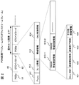
図2は、OLT10からONU30に送信されるPON区間の下りフレームのフォーマットの1例を示す。ここでは、G−PONに適用されるGTCダウンストリームフレームのフォーマットを示してある。
FIG. 2 shows an example of the format of the downstream frame in the PON section transmitted from the
GTCダウンストリームフレーム60は、ヘッダ部(PCBd)61と、GTCペイロード62とからなっている。GTCペイロード62は、特定のONU宛のユニキャストフレームや、複数のONUが受信すべきブロードキャストフレームまたはマルチキャストフレームを、PON区間に固有のフォーマットであるGEMフレーム形式で複数フレーム含んでいる。各ONUは、GTCペイロード62から抽出されたGEMフレームのヘッダが示すONU識別子をチェックし、受信処理すべきフレームを選択する。
The GTC
OLT10は、GTCダウンストリームフレーム60を基本フレーム周期ΔTF、例えば、125マイクロ秒毎に周期的に送出する。GTCダウンストリームフレームのヘッダ部61は、受信側(ONU30側)でフレーム同期を取るための特定の信号パターンを含むPsyncフィールド611と、各ONU103に上りフレームの送信時間帯を通知するための帯域情報フィールド613と、各ONUに起動、停止など制御情報を通知するためのONU制御情報フィールド614と、その他のフレーム情報フィールド612とからなる。フレーム情報フィールド612には、例えば、そのフレームでのFEC処理の有無、フレームカウンタ、BIP、ヘッダ長などの情報が含まれる。但し、フレーム情報フィールド612とONU制御情報フィールド614の内容は、状況に応じて削除される場合がある。
The
帯域情報フィールド613は、ONU毎の複数の帯域制御情報フィールド613−1、613−2、・・・からなる。各帯域制御情報フィールド613−iは、ONUを識別するための帯域制御ID(Alloc−ID)621と、上りフレームの送信時間帯(割当て帯域)を示す送信開始時刻622および送信終了時刻623と、その他の制御情報624を示している。その他の制御情報624としては、例えば、ONUからOLTへの送信キューの状態通知の要否や、上りフレームでのFECの要否などを指定する制御情報が含まれる。
The
帯域情報フィールド613で通知される帯域情報の宛先ONU(Alloc−ID)621は、ペイロード部62に含まれるGEMフレームの宛先ONUとは無関係である。OLT10は、125マイクロ秒×N(例えば、N=4〜6)の周期で、制御下にある各ONU30に割り当てるべき帯域を計算する。OLT10は、各ONUにおける上り送信キューの状態(例えば、送信待ちデータ量を示すキュー長)に応じて、送信待ちデータ量の多いONUに長い送信時間帯が割当てられるように、上り方向の125マイクロ秒×Nの送信時間帯を複数の時間帯に分割して、各ONUの割当て帯域を決定する。
The bandwidth information destination ONU (Alloc-ID) 621 notified in the
例えば、OLT10にm台のONU30が接続されていた場合、各GTCダウンストリームフレームは、m台のONUのうちの一部に対する帯域制御情報を含み、OLT10は、連続するN回のGTCダウンストリームフレームの送信によって、全ONUへの割当て帯域通知を完了する。各ONUは、受信したGTCダウンストリームフレームから自Alloc−IDをもつ帯域制御情報を見つけて、その帯域制御情報が示す送信開始時刻622と送信終了時刻623に従って、上り方向のデータ送信を行う。
For example, when
本発明では、GW50が出力ポート毎に送信キュー長QLを監視し、送信キュー長QLが予め決められた第1閾値HT1を超えた時、バッファ不足による通信フレーム廃棄の発生を未然に防止するために、OLT10に対して、出力ポート番号を指定した輻輳発生通知フレームを送信する。各OLT10は、上記輻輳発生通知フレームで指定された出力ポート(以下、輻輳ポートと言う)に向かう特定ONUからの送信データ量だけを抑制する帯域抑制モードで、各OLTに帯域を割り当てる。
In the present invention, the
GW50は、OLTへのバックプレッシャによって、輻輳ポートの送信キュー長が、上記第1閾値TH1よりも低い第2閾値TH2以下に減少した時、各OLT10に対して、出力ポート番号を指定した輻輳解除通知フレームを送信する。各OLT10は、上記輻輳解除通知フレームで指定された出力ポートに向かう送信データ量の抑制を解除し、各ONUにおける上り送信キュー状態に応じた正常モードの帯域割当て制御に戻る。
When the transmission queue length of the congestion port decreases to the second threshold value TH2 lower than the first threshold value TH1 due to the back pressure to the OLT, the
図1に示したネットワーク構成の場合、例えば、回線101−2と接続された出力ポートの送信キュー長が第1閾値TH1を超えた時、GW50−1からOLT10−1−1〜10−1−nに輻輳発生通知フレームが送信され、OLT10−1−1〜10−1−nが、ISP網103を介してインターネット104と通信中のONUに対する割当て帯域を減少させることになる。
In the case of the network configuration shown in FIG. 1, for example, when the transmission queue length of the output port connected to the line 101-2 exceeds the first threshold TH1, the GW 50-1 to the OLTs 10-1-1 to 10-1- The congestion occurrence notification frame is transmitted to n, and the OLTs 10-1-1 to 10-1-n reduce the allocated bandwidth for the ONU communicating with the
後述するように、本発明の1実施例では、各OLTが、接続関係にあるGW50の出力ポート番号とONU識別子との対応関係を記憶した輻輳制御テーブルを備えており、GW50から輻輳発生通知フレームを受信した時、上記輻輳制御テーブルから輻輳ポート番号と対応するONU識別子を特定し、このONU識別子をもつONUへの割当て帯域を減少させるように、帯域抑制モードでの各OLTへの帯域を割り当てを行う。
As will be described later, in one embodiment of the present invention, each OLT is provided with a congestion control table that stores the correspondence between the output port number of the
また、本発明の1実施例では、各OLTが、ONU識別子と対応して、送信キュー長と、現在の割当て帯域と、予め決められた輻輳時許容帯域との関係を示す帯域制御テーブルを備えており、輻輳ポート番号と対応するONU識別子が特定された時、このONU識別子をもつONUへの割当て帯域を上記帯域制御テーブルで指定された輻輳時許容帯域まで減少させる。また、帯域抑制モードでは、ONUから輻輳ポートに向かう送信データ量の減少によって、PON区間での帯域に余裕ができるため、OLT10は、輻輳ポート以外の正常ポートにデータを送信している他のONUへの割当て帯域を増加することによって、PON区間の帯域を有効に利用する。
Further, in one embodiment of the present invention, each OLT includes a bandwidth control table indicating a relationship between a transmission queue length, a current allocated bandwidth, and a predetermined allowable bandwidth at the time of congestion corresponding to the ONU identifier. When the ONU identifier corresponding to the congestion port number is specified, the allocated bandwidth to the ONU having this ONU identifier is reduced to the congestion allowable bandwidth specified in the bandwidth control table. Further, in the bandwidth suppression mode, since the amount of transmission data from the ONU to the congestion port is reduced, the bandwidth in the PON section can be afforded, so the
図3は、GW50からOLT10に送信される輻輳発生/解除通知フレーム(バックプレッシャ制御フレーム)のフォーマットの1例を示す。
バックプレッシャ制御フレームには、例えば、イーサネットのVLAN(Virtual Local Area Network)タグ付きのフレームフォーマットが適用される。バックプレッシャ制御フレームは、宛先MAC(Media Access Control)アドレス601と、送信元MACアドレス602と、VLANタグ603と、輻輳ビット604と、輻輳ポート番号605とを含む。
FIG. 3 shows an example of a format of a congestion occurrence / release notification frame (back pressure control frame) transmitted from the
For example, a frame format with an Ethernet VLAN (Virtual Local Area Network) tag is applied to the back pressure control frame. The back pressure control frame includes a destination MAC (Media Access Control)
宛先MACアドレス601は、GW50に収容された各OLT10のMACアドレスを示し、送信元MACアドレス602は、GWとOLT10との接続回線を収容しているネットワークインタフェースのMACアドレスを示す。VLANタグ603には、このフレームがバックプレッシャ制御フレームであることを示す特定の値が設定されている。輻輳ビット604には、輻輳発生通知フレームの場合は「1」、輻輳解除通知フレームの場合は「0」が設定される。輻輳ポート番号605は、輻輳が検知されたGW出力ポート番号を示す。
The
上記バックプレッシャ制御フレームを受信した各OLTは、VLANタグ603の値によって、受信フレームがバックプレッシャ制御フレームであることを認識し、輻輳ビット604の値によって、受信フレームが輻輳発生通知か輻輳解除通知かを判断できる。また、輻輳ポート番号605と、前述した輻輳制御テーブルおよび帯域制御テーブルによって、割当て帯域を減少させるべきONUを特定することができる。
Each OLT that has received the back pressure control frame recognizes that the received frame is a back pressure control frame from the value of the
図4は、OLT10の構成例を示すブロック図である。
OLT10は、OLT制御部11と、パラメータメモリ12と、PONの光ファイバ106に接続された光送受信部13と、GW50と接続するためのイーサネット回線105に接続されたイーサネットインタフェース(IF)14と、上記光送受信部13とイーサネットインタIF14との間に接続された上り信号処理回路および下り信号処理回路からなる。パラメータメモリ12には、図5、図6で後述する帯域制御テーブル120と、輻輳制御テーブル130が形成されている。
FIG. 4 is a block diagram illustrating a configuration example of the
The
上り信号処理回路は、光送受信部13で受信した光信号を電気信号に変換する光/電気変換部15と、光/電気変換部15に接続された上りフレーム終端部16と、上りフレーム終端部15から出力された上りフレームを一時的に蓄積する上りデータバッファ17と、上りデータバッファ17からフレームを読出し、イーサネットIF14に送信する上りフレーム送信部18とからなる。上りフレーム終端部16は、光/電気変換部15の出力信号から上りフレームを再生し、フレームヘッダから抽出した送信元キュー長などの制御情報をOLT制御部11に出力すると共に、受信フレームをイーサネット形式のデータフレームに変換して、上りデータバッファ304に出力する。
The upstream signal processing circuit includes an optical /
下り信号処理回路は、イーサネットIN14に接続されたフレーム解析部19と、フレーム解析部19から出力されたユーザフレームを一時的に蓄積する下りデータバッファ20と、図2で説明した下りPONフレーム(GTCダウンストリームフレーム)を所定周期ΔTFで生成し、下りPONフレームのペイロードに、下りデータバッファ20から読み出したユーザフレームまたはOLT制御部11から出力された制御フレームをGEMフレーム形式でマッピングする下りフレーム生成部21と、下りフレーム生成部21から出力された下りPONフレームを電気信号として送信するための下りフレーム送信部22と、下りフレーム送信部22から出力された電気信号を光信号へ変換する電気/光変換部23とからなる。フレーム解析部19は、イーサネットIN14からの受信フレームを解析し、ユーザフレームは下りデータバッファ20に出力し、バックプレッシャ制御フレームはOLT制御部11に転送する。
The downlink signal processing circuit includes a
OLT制御部11は、パラメータメモリ12に形成された帯域制御テーブル120が示す送信元キュー長に基いて、各ONU30に割当てるべき帯域を所定周期で計算し、結果を帯域制御テーブル120に反映する。OLT制御部11が行う割当て帯域の計算については、後で図9を参照して詳述する。
Based on the transmission source queue length indicated by the bandwidth control table 120 formed in the
帯域制御テーブル120は、図5に示すように、ONU識別子である帯域制御ID(Alloc−ID)121と対応した複数のテーブルエントリからなる。各テーブルエントリは、ONU毎に予め決められた輻輳時許容帯域(Bcon)122および最大制御帯域(Bmax)123と、OLT制御部11によって算出された割当て帯域(BW)124と、ONUの送信元キュー長(SQ)125と、輻輳フラグ126と、繰越帯域127とを示す。送信元キュー長(SQ)125は、上りフレーム終端部303から通知された各ONU30の最新の送信キュー長の値を示している。
As shown in FIG. 5, the bandwidth control table 120 includes a plurality of table entries corresponding to a bandwidth control ID (Alloc-ID) 121 that is an ONU identifier. Each table entry includes an allowable bandwidth (Bcon) 122 and a maximum control bandwidth (Bmax) 123 that are determined in advance for each ONU, an allocated bandwidth (BW) 124 calculated by the
輻輳制御テーブル130は、図6に示すように、GW出力ポート番号131と対応して、輻輳フラグ132と、GW出力ポート番号131で特定されたGW出力回線を利用するONUの識別子(帯域制御ID)133との関係を示す複数のテーブルエントリからなっている。
As shown in FIG. 6, the congestion control table 130 corresponds to the GW
OLT制御部11は、フレーム解析部19から図3に示したバックプレッシャ制御フレームを受信した時、上記パラメータメモリ12に形成された輻輳制御テーブル130を参照して、バックプレッシャ制御フレームが示す輻輳ポート番号605と対応するテーブルエントリの輻輳フラグ132を受信フレームの輻輳ビット605に合わせて更新し、輻輳制御対象となるONU識別子(帯域制御ID)133を特定する。この後、OLT制御部11は、帯域制御テーブル120から上記帯域制御ID133と対応するテーブルエントリを検索し、輻輳フラグ126の値を更新する。但し、バックプレッシャ制御フレームが輻輳発生通知フレーム(輻輳フラグ=「1」)の場合は、輻輳フラグ126が直ちに「1」に変更されるが、バックプレッシャ制御フレームが輻輳解除通知フレーム(輻輳フラグ=「0」)の場合は、輻輳フラグ126は、次の帯域計算時に「0」に変更される。
When the
図7は、ONU30の構成例を示すブロック図である。
ONU30は、ONU制御部31と、加入者端末TEと接続するためのイーサネット回線109に接続されたイーサネットインタフェース(IF)32と、PONの支線光ファイバ108に接続された光送受信部33と、上記イーサネットIF32と光送受信部33との間に接続された上り信号処理回路および下り信号処理回路とからなる。
ONU制御部31は、上りデータバッファ管理部311と、制御フレーム生成部312と、上り送信タイミング生成部313とからなっている。
FIG. 7 is a block diagram illustrating a configuration example of the
The
The
上り信号処理回路は、イーサネットIFで受信した上りユーザフレームを一時的に蓄積するための上りデータバッファ34と、上りPONフレームを生成する上りフレーム生成部35と、上りフレーム生成部35で生成された上りPONフレームを上り送信タイミング生成部313が示す時間帯で送信するための上りフレーム送信部36と、上りフレーム送信部36から出力された電気信号を光信号へ変換する電気/光変換部37とからなる。
The upstream signal processing circuit is generated by the
下り信号処理回路は、光送受信部33で受信した支線光ファイバ108からの光信号を電気信号に変換する光/電気変換部38と、光/電気変換部38に接続された下りフレーム終端部39と、下りフレーム終端部39から出力された自ONU宛のユーザフレームを一時的に蓄積する下りデータバッファ40と、下りデータバッファ40から読み出したユーザフレームおよび制御フレーム生成部312から供給された制御フレームをイーサネットIF32に送出するための下りフレーム送信部41とからなる。
The downstream signal processing circuit includes an optical /
下りフレーム終端部39は、光/電気変換部38の出力信号を下りPONフレーム(GTCダウンストリームフレーム)に変換し、フレームヘッダ(PCBd)から抽出した自ONUへの割当て帯域情報を上り信号タイミング生成部313に供給すると共に、GTCペイロードから自ONU宛のユーザフレームを抽出し、イーサネット形式のデータフレームに変換して、下りデータバッファ40に出力する。
The downstream
上り送信タイミング生成部313は、上記割当て帯域情報が示す送信開始時刻、送信終了時刻と、予めOLT10から通知してある等価遅延時間とに基いて、上りフレームの送信時間帯を決定し、上りフレーム生成部35、上りフレーム送信部36、上りバッファ管理部311を制御する。
The uplink transmission
上りデータバッファ管理部311は、上りデータバッファ34のデータ蓄積量(送信キュー長)を監視しており、送信キュー長が所定閾値以上となった時、制御フレーム生成部312にポーズフレーム生成のための制御信号を発生し、上り送信タイミング生成部313から指示されたタイミングで、現在の送信キュー長を上りフレーム生成部35に通知する。上りフレーム生成部35は、上り送信タイミング生成部313から指示に従って、ヘッダに上りバッファ管理部311から通知された送信キュー長情報を含み、ペイロードに上りデータバッファ34から読み出したユーザフレームを含む上りPONフレームを生成し、上りフレーム送信部36に出力する。
The upstream data
制御フレーム生成部312は、上りデータバッファ管理部311からの制御信号に応じて、加入者端末TEにデータ送信を抑制させるための制御フレーム(ポーズフレーム)を生成し、これを下りフレーム送信部41に出力する。下りフレーム送信部41は、制御フレーム生成部312からのポーズフレームがなければ、下りデータバッファ40から読み出したユーザフレームをイーサネットIF32に送出し、ポーズフレームが発生した場合は、ポーズフレームをイーサネットIF32に送出する。
The control
加入者端末TEが、上記ポーズフレームに応答してデータ送信を抑制した結果、上りデータバッファ34のキュー長が輻輳解除閾値を下回った時、上りデータバッファ管理部311から制御フレーム生成部312に輻輳解除の制御信号が与えられる。上記制御信号に応答して、制御フレーム生成部312は、データ送信の抑制を解除する制御フレームを生成し、これを下りフレーム送信部41に出力する。
When the subscriber terminal TE suppresses data transmission in response to the pause frame and the queue length of the
図8は、GW50−1の構成例を示すブロック図である。
GW50−1は、それぞれイーサネット回線(105または101)と接続される複数のネットワークインタフェース(NIF:Network InterFace)部51(51−1〜51−q)と、これらのNIF部51を相互接続するフレーム中継部52と、GW管理部53と、GW管理部53が参照するGW管理情報を保持した管理情報テーブル54とからなっている。各NIF部51は、イーサネットの入出力回線を収容するイーサネットIF511に接続された入力回線インタフェース部51Aと、出力回線インタフェース部51Bとからなる。
FIG. 8 is a block diagram illustrating a configuration example of the GW 50-1.
The GW 50-1 has a plurality of network interface (NIF) units 51 (51-1 to 51 -q) connected to the Ethernet line (105 or 101), and a frame for interconnecting these NIF units 51. The
入力回線インタフェース部51Aは、ヘッダ処理のためのパラメータ情報を保持するパラメータテーブル513と、イーサネットIF511から受信したフレームのヘッダを解析し、パラメータテーブル513に従って、受信フレームに内部ルーティング情報を含む内部ヘッダを付加する入力ヘッダ解析処理部512と、入力ヘッダ解析処理部512から出力されたフレームを一時的に蓄積する入力フレームバッファ514と、入力フレームバッファ514からフレームを読出し、フレーム中継部52に出力する入力フレーム読出し部515とからなる。
The input
フレーム中継部52は、各入力回線インタフェース部51Aから受信したフレームを、内部ルーティング情報で決まる特定出力ポートの出力回線インタフェース部51Bに中継する。前述したように、本発明では、キャリア網内ではONU毎に固定のパスが設定してあるため、上記フレーム中継部52によるフレーム転送において、ONU103毎にフレームの出力ポートが固定的となる。
The
出力回線インタフェース部51Bは、パラメータテーブル517と、フレーム中継部52から受信したフレームのヘッダを解析し、内部ヘッダの除去とパラメータテーブル517の設定に従ったヘッダ処理を行う出力ヘッダ解析処理部516と、出力ヘッダ解析処理部516から出力されたフレームを一時的に蓄積する出力フレームバッファ518と、出力フレームバッファ519のデータの蓄積量(キュー長)を監視し、GW管理部53にキュー長情報を出力するキュー長モニタ519と、出力フレームバッファ518から出力フレームを読み出して、イーサネットIF511に送出するための出力フレーム読出し部520と、バックプレッシャ制御フレーム生成部521とからなる。
The output line interface unit 51B analyzes the parameter table 517 and the header of the frame received from the
パラメータテーブル517には、ヘッダ処理に必要なパラメータ情報と、バックプレッシャ制御フレームの生成に必要な宛先MACアドレス(OLTのMACアドレス)と送信元MACアドレス(イーサネットIFのMACアドレス)が記憶されている。但し、OLTが接続されていない出力回線インタフェース部51Bでは、これらのMACアドレスを記憶する必要はない。管理情報テーブル54には、輻輳発生を検知するための第1閾値TH1と、輻輳解除を検知するための第2閾値TH2と、出力ポート(出力回線インタフェース部51B)毎の輻輳状態を示す輻輳フラグが記憶されている。ここで、第1閾値と第2閾値は、TH1>TH2の関係にある。 The parameter table 517 stores parameter information necessary for header processing, a destination MAC address (OLT MAC address) and a source MAC address (Ethernet IF MAC address) necessary for generating a backpressure control frame. . However, the output line interface unit 51B to which the OLT is not connected need not store these MAC addresses. The management information table 54 includes a first threshold value TH1 for detecting occurrence of congestion, a second threshold value TH2 for detecting congestion release, and a congestion flag indicating a congestion state for each output port (output line interface unit 51B). Is remembered. Here, the first threshold value and the second threshold value have a relationship of TH1> TH2.
GW管理部53は、各出力回線インタフェース部51Bのキュー長モニタ519からキュー長QLを受信すると、キュー長QLを閾値TH1、TH2と比較する。GW管理部53は、或る出力ポートPiの出力フレームバッファ518のキュー長QLが第1閾値Th1を超えた時、管理情報テーブル54の上記出力ポートPiと対応する輻輳フラグを「1」に設定し、他の出力ポートに所属するバックプレッシャ制御フレーム生成部521に対して、輻輳発生を通知する。
When receiving the queue length QL from the queue length monitor 519 of each output line interface unit 51B, the
GW管理部53は、輻輳フラグが「1」に設定された出力ポートPiについては、キュー長モニタ519からその後に受信する出力フレームバッファ518のキュー長QLを第2閾値TH2と比較し、キュー長QLが第2閾値TH2を下回った時点で、輻輳フラグを「0」に変更し、他の出力ポートに所属するバックプレッシャ制御フレーム生成部521に対して、輻輳解除を通知する。上記輻輳発生通知と輻輳解除通知には、VLANタグの値と、輻輳の発生/解除を示す輻輳ビットと、輻輳が発生(または解除)した出力回線インタフェース部51Bを示す出力ポート番号とが含まれている。
For the output port Pi for which the congestion flag is set to “1”, the
各出力回線インタフェース部51Bのバックプレッシャ制御フレーム生成部521は、GW管理部53から輻輳発生通知または輻輳解除通知を受信すると、パラメータテーブル517からMACアドレス情報を読み出し、図3に示したバックプレッシャ制御フレームを生成して、出力フレーム読出し部520に出力する。出力フレーム読出し部520は、バックプレッシャ制御フレームを受信すると、出力フレームバッファ518から読み出し中の1つのフレームの送信が完了した時点で、バックプレッシャ制御フレームイーサネットIF511に送出し、その後で出力フレームバッファ518からのフレームの読出し/送信動作を再開する。
When the back pressure control frame generation unit 521 of each output line interface unit 51B receives the congestion occurrence notification or the congestion release notification from the
図9は、OLT10のOLT制御部11が実行する帯域制御処理110のフローチャートを示す。OLT制御部11は、図2に示した基本フレーム周期ΔTF(125マイクロ秒周期)で帯域制御処理110を実行し、ΔTF×N周期で各ONUへの割当て帯域を計算する。以下の説明では、Nの値をMAX、帯域制御処理110の実行回数をパラメータiで表す。
FIG. 9 shows a flowchart of the bandwidth control processing 110 executed by the
帯域制御処理110において、OLT制御部11は、パラメータiの値をインクリメント(i=i+1)し(ステップ111)、GWから新たなバックプレッシャ制御フレームを受信したか否かをチェックする(112)。もし、バックプレッシャ制御フレームが受信されていなければ、パラメータiの値がMAXに達したか否かを判定し(117)、iの値がMAXよりも小さければ、この処理を終了する。パラメータiの値がMAXに達していた場合、後述する割当て帯域の計算と、帯域制御テーブル120の更新を実行する。
In the
GWから新たなバックプレッシャ制御フレームを受信していた場合、OLT制御部11は、受信フレームに含まれる輻輳ビット604をチェックする(113)。もし、輻輳ビット604が「1」、すなわち、受信フレームが輻輳発生通知フレームの場合、OLT制御部11は、輻輳制御テーブル130と帯域制御テーブル120において、受信フレームが示す輻輳ポート番号605と対応する輻輳フラグ132、126を「1」に設定(114)した後、パラメータiの値がMAXに達したか否かを判定する(117)。
If a new back pressure control frame has been received from the GW, the
ステップ114は、具体的には、OLT制御部11が、輻輳制御テーブル130から輻輳ポート番号605に該当するテーブルエントリを検索して、輻輳フラグ132を「1」に設定した後、該テーブルエントリが示す帯域制御ID133に従って帯域制御テーブル120を参照し、帯域制御ID133と対応する各テーブルエントリの輻輳フラグ126を「1」に設定することを意味している。
Specifically, in
受信フレームに含まれる輻輳ビット604が「0」、すなわち、受信フレームが輻輳解除通知フレームの場合、OLT制御部11は、輻輳ポート番号605の値を輻輳解除ポート番号としてワークエリアに記憶(116)した後、パラメータiの値がMAXに達したか否かを判定する(117)。パラメータiの値がMAXよりも小さければ、この処理を終了する。
When the
パラメータiの値がMAXに達していた場合、OLT制御部11は、ワークエリアの輻輳解除ポート番号をチェックし(118)、もし、輻輳解除ポート番号が記憶されていなければ、帯域制御テーブル120に基いて各ONUに割り当てるべき新たな帯域を計算し、帯域制御テーブル120に新たな割当て帯域124を記憶する(121)。この後、パラメータiの値を初期値「1」に設定して、この処理を終了する。
If the value of the parameter i has reached MAX, the
ワークエリアに輻輳解除ポート番号が記憶されていた場合、OLT制御部11は、輻輳制御テーブル130と帯域制御テーブル120において、上記輻輳解除ポート番号と対応する輻輳フラグ132、126を「0」に変更し(119)、ワークエリアの輻輳解除ポート番号をクリア(120)した後、各ONUに割り当てるべき新たな帯域を計算する(121)。
When the congestion release port number is stored in the work area, the
本発明において、OLT制御部11が実行する帯域割当ての計算モードには、通常モードと帯域抑制モードとがある。通常モードでは、例えば、ITU−T勧告G983.4、G984.3に規定された動的帯域割り当て(DBA:Dynamic Bandwidth Allocation)機能によって、帯域制御テーブル120が示す送信元キュー長125に応じた帯域が各ONUが割り当てられる。具体的に言うと、例えば、帯域制御テーブル120が示す送信元キュー長125の合計値を求め、キュー長の合計値と各ONUの送信元キュー長125との比率によって、ONU毎の重みを計算し、この重みの値に従って、PON区間のΔTF×N期間の上り帯域を各ONUに分配する。
In the present invention, the bandwidth allocation calculation modes executed by the
帯域抑制モードの帯域割当ては、GWの何れかの出力ポートで輻輳が発生した場合に実行される。帯域抑制モードでは、帯域制御テーブル120で輻輳フラグ126が「1」状態にあるONUに対して、輻輳時許容帯域122が示す帯域が割り当てられる。輻輳時許容帯域122は、通常モードで割当てられる割当て帯域124よりも小さいため、GWの輻輳ポートに向かう論理パスの通信帯域を割当て帯域124から輻輳時許容帯域122に減少させた場合、PON区間の上り帯域に余裕ができる。そこで、本発明の帯域抑制モードでは、例えば、PON区間のΔTF×N期間の上り帯域から、輻輳フラグ126が「1」状態にあるテーブルエントリが示す輻輳時許容帯域122の合計値を減算し、残った帯域を上述した通常モードと同様の方法で他のONUに分配する。
Bandwidth allocation in the bandwidth suppression mode is executed when congestion occurs at any output port of the GW. In the band suppression mode, a band indicated by the congestion
図10は、本発明でOLT10が行う通常モードと帯域抑制モードの帯域割当てを模式的に示した図である。
ここでは、簡単化のために、OLT10に8台のONU30が接続され、OLT制御部11が、基本フレーム周期ΔTFの3倍(N=3)の周期ΔTDで、各ONUへの割当て帯域を計算する場合について説明する。また、通常モードでの割当て帯域と、帯域抑制モードでの割当て帯域との違いを判り易くするため、各ONUの送信キュー長が、図示された期間内では一定とする。斜線で示したフレームF2(F12、F22)、F3(F13、F23)、F6(F16、F26)は、GWの輻輳ポートに向かうONU2、ONU3、ONU6の割当て帯域を表している。
FIG. 10 is a diagram schematically illustrating bandwidth allocation in the normal mode and the bandwidth suppression mode performed by the
Here, for simplification, eight
本実施例では、OLT制御部11が、周期ΔTDで帯域制御テーブル120の割当て帯域124の値を更新し、下りフレーム生成部21が、下りPONフレームの帯域情報フィールド613によって、上記帯域制御テーブル120が示す割当て帯域124を各ONUに通知する。OLT制御部11は、GW50から輻輳通知を受信すると、図9で説明したように、帯域制御テーブル120の輻輳ポートと対応する輻輳フラグ126を「1」に設定する。本実施例では、下りフレーム生成部21は、帯域制御テーブル120の輻輳フラグ126をチェックし、輻輳フラグ126が「0」のONUに対しては、割当て帯域124を通知し、輻輳フラグ126が「1」のONUに対しては、輻輳時許容帯域122を通知する。
In this embodiment, the
図10の(A)に示したフレーム周期ΔTF(1)〜ΔTF(3)は、横軸を時間軸として、通常モードで割り当てられたONU1〜ONU8の上りフレーム送信帯域を示している。(B)は、ONU2がフレームF12を送信中に、OLT制御部11がGW50から輻輳通知を受信した場合のフレーム周期ΔTF(4)〜ΔTF(6)における上りフレーム送信帯域を示す。
Frame periods ΔTF (1) to ΔTF (3) shown in FIG. 10A indicate the upstream frame transmission bands of ONU1 to ONU8 assigned in the normal mode with the horizontal axis as the time axis. (B) shows the upstream frame transmission band in the frame periods ΔTF (4) to ΔTF (6) when the
上述したように、OLT制御部11は、周期ΔTDで帯域制御テーブル120の割当て帯域124の値を更新しているため、フレーム周期ΔTF(4)〜ΔTF(6)の期間内では、各ONUの割当て帯域124の値は変更されない。しかしながら、本実施例では、下りフレーム生成部21が、輻輳フラグ126が「1」のONUに対して輻輳時許容帯域122を通知している。これによって、GWの輻輳ポートに向かうONU6からの上りフレームの帯域が減少し、結果的に、フレーム周期TF(6)の最後に空き帯域BW(V)が発生している。
As described above, since the
OLT制御部11が、フレーム周期ΔTF(6)とΔTF(7)との間で、帯域制御テーブル120の割当て帯域124の値を更新すると、図(C)に示すように、フレーム周期ΔTF(6)TF(7)〜ΔTF(6)TF(9)では、ONU1〜ONU8に通知される帯域が変化する。帯域抑制モードの帯域割当てによって、輻輳ポートに向かう上りフレームを送信中のONU2、ONU3、ONU6の帯域は全て輻輳時許容帯域122となり、正常ポートに向かう上りフレームを送信中のその他のONUの帯域は、正常モードの時よりも増加する。図10では、ONU7が上りフレームF27を送信している間に、OLT制御部11が、GW50から輻輳解除通知を受信した場合を想定している。本実施例では、帯域抑制モードによる最適な帯域制御期間T2の前後に過渡期間T1とT2が発生している。
When the
図11は、OLTの下りフレーム生成部21が、基本フレーム周期ΔTF(125マイクロ秒周期)で実行する下りPONフレーム生成処理210のフローチャートを示す。
FIG. 11 shows a flowchart of a downstream PON
下りフレーム生成部21は、図2に示したGTCフレームヘッダ(PCBd)のPsyncフィールド611とフレーム情報フィールド612(ステップ211)、帯域情報フィールド613(ステップ212)、ONU制御情報フィールド614(ステップ213)を生成した後、下りデータバッファ20から読み出したユーザフレームと、OLT制御部11が生成した制御フレームをGEMフレーム形式でマッピングしたGTCペイロード62を生成する(214)。
The downlink
図12は、帯域情報フィールドの生成処理(212)の詳細フローチャートの1例を示す。OLT制御部11が帯域制御テーブル120に設定した割当て帯域124は、ΔTF×N期間における各ONUの上り帯域を示している。下りフレーム生成部21は、帯域制御テーブル120の帯域制御ID121が示す全ONU30に対して、帯域制御テーブル120が示す割当て帯域124をN個の下りPONフレームに分けて通知する。
FIG. 12 shows an example of a detailed flowchart of the band information field generation process (212). The allocated
図12において、パラメータiは、図10に示した期間ΔTD内の基本フレーム周期ΔTFの位置を示し、パラメータjは、帯域制御テーブル120におけるテーブルエントリの位置を示す。また、MAXは、期間ΔTDに含まれる基本フレーム周期の数Nを示している。 12, parameter i indicates the position of the basic frame period ΔTF within the period ΔTD shown in FIG. 10, and parameter j indicates the position of the table entry in the bandwidth control table 120. MAX indicates the number N of basic frame periods included in the period ΔTD.
下りフレーム生成部21は、パラメータiの値を「MAX+1」と比較し(ステップ220)、i=MAX+1、つまり、新たな期間ΔTDに入った時、パラメータi、jの値を初期値「1」に設定し(221)、今回生成する下りPONフレーム(第i基本フレーム周期)でONUに割当て可能な帯域のトータル値(使用可能BW)を初期値に設定する(222)。
The downstream
下りフレーム生成部21は、次に、パラメータjと帯域制御テーブル120のテーブルエントリ数とを比較し(223)、パラメータjがテーブルエントリ数を超えた場合は、この処理を終了する。パラメータjがテーブルエントリ数を超えていなければ、下りフレーム生成部21は、帯域制御テーブル120から第jテーブルエントリを読み出し(224)、輻輳フラグ126をチェックする(225)。輻輳フラグ126が「1」の場合、下りフレーム生成部21は、変数BW(j)に上記第jテーブルエントリが示す輻輳時許容帯域122の値を設定し(226)、輻輳フラグ126が「0」の場合は、変数BW(j)に上記第jテーブルエントリが示す割当て帯域124の値を設定する(227)。
Next, the downlink
下りフレーム生成部21は、次に、上記第jテーブルエントリの繰越帯域127をチェックし(228)、繰越帯域127がゼロの場合は、使用可能BWとBW(j)とを比較する(231)。繰越帯域127がゼロでなければ、下りフレーム生成部21は、BW(j)に繰越帯域127の値を設定し(229)、上記第jテーブルエントリの繰越帯域127をクリア(230)した後、使用可能BWとBW(j)とを比較する(231)。
Next, the downlink
ここで、繰越帯域は、例えば、図10にF3で示すように、第jテーブルエントリで指定された帯域(輻輳時許容帯域または割当て帯域)が、2つの基本フレーム周期に跨った場合に、次の基本フレーム周期でONUに通知される帯域部分を意味している。実際の応用においては、第jテーブルエントリで指定された帯域を1つの基本フレーム周期で通知しておき、繰越帯域を次の基本クレーム周期の使用可能BWから差し引いてもよい。 Here, for example, as shown by F3 in FIG. 10, the carryover bandwidth is the following when the bandwidth (congested bandwidth or allocated bandwidth) specified in the jth table entry straddles two basic frame periods. This means a bandwidth portion notified to the ONU in the basic frame period. In an actual application, the band designated by the jth table entry may be notified in one basic frame period, and the carryover band may be subtracted from the usable BW of the next basic claim period.
使用可能BWがBW(j)以上であれば、下りフレーム生成部21は、BW(j)に基いて、送信開始時刻と送信終了時刻を計算する(234)。もし、使用可能BWがBW(j)よりも少ない場合、下りフレーム生成部21は、BW(j)に使用可能BWを設定し(232)、不足した帯域を第jテーブルエントリに繰越帯域として記憶(233)した後、BW(j)に基いて、送信開始時刻と送信終了時刻を計算する(234)。
If the available BW is equal to or greater than BW (j), the
下りフレーム生成部21は、下りPONフレームに、上記第jテーブルエントリが示す帯域制御IDに付随させて上記送信開始時刻と送信終了時刻とを含む帯域制御情報を設定し(235)、使用可能BWからBW(j)の値を差し引き(236)、使用可能BWの値を予め決められた帯域最小値BWminと比較する(237)。下りフレーム生成部21は、使用可能BWがBWmin以上であれば、パラメータjの値をインクリメントして(238)、制御シーケンスをステップ223に戻し、使用可能BWがBWminよりも小さければ、パラメータiの値をインクリメントして(239)、この処理を終了する。
The downlink
図13は、GW50、OLT10、ONU30の間で実行される本発明による輻輳制御のシーケンス図を示している。
FIG. 13 shows a sequence diagram of congestion control executed between the
GW50は、出力ポート(出力回線インタフェース)毎のキュー長QLを監視し、キュー長QLが閾値TH1を超えた時、バックプレッシャ制御フレーム(輻輳発生通知)を発行し(輻輳発生検知401)、そのキュー長QLが閾値TH2を下回った時、輻輳ポートを指定したバックプレッシャ制御フレーム(輻輳解除通知)を発行する(輻輳解除検知404)。バックプレッシャ制御フレーム(輻輳発生/解除通知)は、GW50に接続されている全てのOLT宛に送信される。
The
OLT10は、基本フレーム周期ΔTFで、下りPONフレームDF1、DF2、DF3、DF4、・・・を送信している(SQ01、SQ02、SQ04、SQ05)。GW50の出力ポートが正常状態にある間、OLT10は、通常モードで割り当てた帯域(U−BWs)を各ONUに通知している。OLT10に接続されたONU30−kは、自分宛の帯域制御情報を含む下りPONフレームDF2を受信すると、帯域制御情報が示す送信開始時刻に等価遅延を加えた適切なタイミング(ΔTS)で、上りフレームUFiの送信を開始する(SQ03)。
The
OLT10は、GW50から輻輳発生通知を受信すると、輻輳制御テーブル130と帯域制御テーブル120において、通知されたGW出力ポート番号と対応する輻輳フラグを「1」に設定する(402)。輻輳フラグが「1」となった後、OLT10が帯域割当て周期ΔTDで帯域割当て処理(403)を実行して、帯域制御テーブル120が更新されるまでの期間が、図10で説明した過渡期間T1となる。
When receiving the congestion occurrence notification from the
GW50が輻輳状態にある時、帯域制御テーブル120が一旦更新されると、OLT10による帯域制御が最適制御期間T2となる。最適制御期間T2に送信される下りPONフレーム(SQ11、SQ12、SQ14)は、GWの正常ポートを利用するONUには拡張割当て帯域(E−BWs)を通知し、輻輳ポートを利用するONUには輻輳時許容帯域(C−BWs)を通知している。従って、もし、ONU30−kが輻輳ポートを利用していた場合、ONU30−kは、輻輳時許容帯域で上りフレームUFi+1を送信(SQ13)することになる。
When the
OLT10は、GW50から輻輳解除通知を受信すると、輻輳解除ポート番号を記憶しておき(405)、帯域割当て周期ΔTDで行う次回の帯域割当て処理(406)において、輻輳フラグを「0」に変更する。従って、GW50が輻輳解除通知を発行してから、OLT10が帯域割当て処理(406)を実行する迄の間は、下りPONフレーム(SQ15)が各ONUに拡張割当て帯域、または輻輳時許容帯域を通知する過渡期間T3となる。
Upon receiving the congestion release notification from the
輻輳解除通知を受信したOLT10が、帯域制御テーブル120を一旦更新すると、OLT10の帯域制御は、下りPONフレームで各ONUに通常時の割当て帯域(U−BWs)を通知する通常モードとなる(SQ21、SQ22)。従って、送信帯域を抑制されていたONU30−kも、通常の割当て帯域で上りフレームUFi+2を送信できる(SQ23)。
When the
図14は、GW50のキュー長モニタ519で観測される或る出力フレームバッファ518のデータ蓄積量(送信キュー長)QLの経時変化と、OLT10が行う帯域制御との関係を示す。TH1は、輻輳発生を検知するための第1閾値、TH2は、輻輳解除を検知するための第2閾値を示し、ΔTDは、OLT10が実行する帯域計算の周期を示している。
FIG. 14 shows the relationship between the temporal change of the data accumulation amount (transmission queue length) QL of an
GW管理部53は、GWの各出力ポート(出力回線インタフェース部)51Bのキュー長モニタ519から、所定周期、例えば、基本フレーム周期ΔTFで、送信キュー長QLを読み込み、キュー長QLが第1の閾値TH1を超えた時、バックプレッシャ制御フレーム生成部521に輻輳発生通知フレームを発行させ、輻輳状態にあった出力ポートのキュー長QLが閾値TH2を下回った時、バックプレッシャフレーム生成部521に輻輳解除通知フレームを発行させている。従って、GW50では、輻輳発生から輻輳解除までの期間が輻輳期間となる。
The
第1閾値TH1は、出力フレームバッファ518の容量よりも小さい値に設定してあるため、輻輳発生通知フレームは、出力フレームバッファが満杯になる前に発行される。また、出力フレームバッファ518は、輻輳発生通知に応答して、各OLT10が帯域を抑制するまでの間のキュー長増加を充分に吸収できるだけの余裕を残している。OLT制御部11は、GW10から帯域発生通知を受信すると、前述した過渡期間T1、T3と最適制御期間T3とからなる帯域抑制モードで、各ONUへの割当て帯域を制御する。
Since the first threshold value TH1 is set to a value smaller than the capacity of the
図15は、OLT10における帯域抑制モード期間151、152と、輻輳が発生したGWポートの通過フレームを送信中のONU(以下、輻輳パスONUと呼ぶ)における送信キュー長153と割当て帯域154の経時変化を模式的に示している。
FIG. 15 shows changes over time in the bandwidth
図16は、OLT10における帯域抑制モード期間151、152と、輻輳のないGW出力ポートの通過フレームを送信中のONU(以下、通常パスONUと呼ぶ)における送信キュー長153と割当て帯域155の経時変化を模式的に示している。
FIG. 16 shows changes over time in the bandwidth
ここでは、本発明による帯域制御効果をより判り易くするため、通常パスONUと輻輳パスONUの送信キュー長変化を同一として、割当て帯域の変化にのみ着目する。OLT制御部11における帯域制御は、基本クレーム周期ΔTFだけ遅れて各ONUに反映される。帯域抑制モード期間151、152以外の期間では、各ONUには、通常モードの帯域計算による送信キュー長153に応じた割当て帯域BW(j)が通知される。
Here, in order to make the bandwidth control effect according to the present invention easier to understand, the transmission queue length changes of the normal path ONU and the congestion path ONU are made the same, and only the change of the allocated bandwidth is focused. Band control in the
OLT制御部11が、時刻t1とt2の間で帯域抑制モード期間151に入ってから、次の帯域割当て処理が実行される迄の間は、過渡期間T1となる。輻輳パスONUに対して、もし過渡期間T1内に次の割当て帯域を通知できた場合、輻輳パスONUの帯域は、図15に示すように、過渡期間T1内に輻輳時許容帯域Bconに抑制される。OLT制御部11が、時刻t2の直前で帯域割当て処理を実行すると、帯域抑制モードは最適制御期間T2に入る。本実施例では、輻輳パスONUへの割当て帯域は、輻輳時許容帯域Bconに維持され、この状態は、GW出力ポートが輻輳状態を脱して、帯域抑制モードが過渡期間T3に遷移した後も継続する。輻輳パスONUの帯域は、OLT10の帯域制御が通常モードに遷移した時、送信キュー長SQに応じた割り当て帯域に戻る。
The transition period T1 is a period from when the
本発明によれば、OLT10が帯域抑制モードとなった時、輻輳パスONUの割当て帯域のみが削減されるため、通常パスONUでは、図16に示すように、帯域抑制モードの過渡期間T1における割当て帯域は従前通りとなる。OLT制御部11の帯域抑制モードが最適制御期間T2に入ると、輻輳パスONUの帯域削減によってPON区間に生じた余裕帯域が、送信キュー長に応じて複数の通常パスONUに分配される。従って、図に示すように、最適制御期間T2では、通常パスONUの割当て帯域が増加する。但し、通常パスONUの帯域は、通常モード時と同様、送信キュー長に応じて割り当てられるため、時刻t8に示すように、送信キュー長SQが短くなれば、割当て帯域は減少する。
According to the present invention, when the
上述した実施例では、OLT制御部11が、帯域抑制モード期間において、輻輳パスONUの帯域を輻輳時許容帯域Bconに維持しているが、輻輳パスONUに対して、輻輳時許容帯域を上限として、送信元キュー長に応じた帯域割当てを行うようにしてもよい。同様に、通常パスONUに対して、帯域制御テーブル120が示す最大制御帯域123を上限として、送信元キュー長に応じた帯域割当てを行うようにしてもよい。
In the above-described embodiment, the
実施例では、各ONUの輻輳時許容帯域を予め固定値として与えているが、輻輳時許容帯域としては、輻輳発生前にONUに割当てられている帯域値に所定の減少率を乗算して得られる動的な値を適用してもよい。 In the embodiment, the allowable bandwidth at the time of congestion of each ONU is given as a fixed value in advance, but the allowable bandwidth at the time of congestion is obtained by multiplying the bandwidth value allocated to the ONU before the occurrence of congestion by a predetermined reduction rate. Applied dynamic values may be applied.
また、実施例では、GW50の各出力回線インタフェース部51Bに、バックプレッシャ制御フレーム生成部521を設け、GW管理部53からの指示に従って、上記バックプレッシャ制御フレーム生成部521が、輻輳発生通知フレームと輻輳解除通知フレームを生成しているが、バックプレッシャ制御フレーム(輻輳発生通知フレームと輻輳解除通知フレーム)をGW管理部53で生成するようにしてもよい。
Further, in the embodiment, each output line interface unit 51B of the
この場合、各出力回線インタフェース部51Bに、バックプレッシャ制御フレーム生成部521に代えて、バックプレッシャ制御フレームバッファを設けておき、管理情報テーブル54に、例えば、GW出力ポート番号と対応して、OLTとの接続ポート番号、接続ポートのMACアドレス、OLTのMACアドレスを記憶しておく。GW管理部53は、出力ポートPiで輻輳発生を検知した時、管理情報テーブル54を参照してバックプレッシャ制御フレームを生成し、これをOLT接続ポート番号と対応する出力回線インタフェース部51Bのバックプレッシャ制御フレームバッファに出力する。出力フレーム読み出し部520には、バックプレッシャ制御フレームバッファを出力フレームバッファ518よりも優先させて、フレームの読み出しと送信を行わせる。
In this case, each output line interface unit 51B is provided with a back pressure control frame buffer instead of the back pressure control frame generation unit 521, and the management information table 54 includes, for example, an OLT corresponding to the GW output port number. Connection port number, connection port MAC address, and OLT MAC address are stored. When detecting the occurrence of congestion at the output port Pi, the
図17は、本発明が適用されるネットワークの他の実施例を示す。
本実施例では、キャリア網を構成するGW500−1、500−2が、OLT機能を備えた回線インタフェース(PONインタフェース)を備え、PONの光ファイバ106(106−1−1〜106−2−n)を直接収容できるようになっている。
FIG. 17 shows another embodiment of a network to which the present invention is applied.
In this embodiment, the GWs 500-1 and 500-2 configuring the carrier network include a line interface (PON interface) having an OLT function, and the PON optical fiber 106 (106-1-1-1 to 106-2-n). ) Can be accommodated directly.
図18は、GW500−1の構成を示す。
GW500−1は、複数のネットワークインタフェース部510(510−1〜510−q)と、これらのインタフェース部510を相互接続するフレーム中継部52と、GW管理部53と、管理情報テーブル54とからなり、PONの光ファイバ106を収容するネットワークインタフェース部51−1は、図8で示したイーサネットIF511に代えて、PONインタフェース(IF)5110を備えている。キャリア網の回線101(101−1、101−2)を収容するネットワークインタフェース部は、図8に示したイーサネットIF511を備えている。
FIG. 18 shows the configuration of the GW 500-1.
The GW 500-1 includes a plurality of network interface units 510 (510-1 to 510-q), a
PONインタフェース(IF)5110は、図4に示したOLT10の構成要素のうち、イーサネットIF14、上りフレーム送信部18、フレーム解析部19を除いた構成要素からなり、OLT制御部11がGW管理部53と接続されている。
The PON interface (IF) 5110 includes constituent elements of the
本実施例によれば、OLT制御部11が、GW管理部53から直接的に輻輳発生通知と輻輳解除通知を受信できるため、図3に示したバックプレッシャ制御フレームの生成に必要な宛先MACアドレスの管理が不要となる。また、本実施例によれば、GW内の出力ポートに輻輳が発生した時、OLT制御部11が、輻輳パスONUの割当て帯域を素早く低減できるため、輻輳パスONUに対するバックプレッシャによる輻輳回避を迅速化することが可能となり、GWの出力フレームバッファのメモリ容量を小さくできる。
尚、実施例では、G−PONへの適用例について説明したが、本発明による帯域制御は、G−PON以外、例えば、GE−PONにも適用可能である。
According to the present embodiment, since the
In addition, although the Example demonstrated the application example to G-PON, the zone | band control by this invention is applicable also to GE-PON other than G-PON, for example.
10:局側装置(OLT)、30:加入者側装置(ONU)、50:フレーム転送装置(GW)、OLT制御部、12:パラメータメモリ、21:下りフレーム生成部、51:ネットワークインタフェース、52:フレーム中継部、53:GW制御部、54:管理テーブル、518:出力バッファ、519:キュー長モニタ、520:出力フレーム読出し部、521:BP制御フレーム生成部、120:帯域制御テーブル、130:輻輳制御テーブル。 10: Station side device (OLT), 30: Subscriber side device (ONU), 50: Frame transfer device (GW), OLT control unit, 12: Parameter memory, 21: Downstream frame generation unit, 51: Network interface, 52 : Frame relay unit, 53: GW control unit, 54: Management table, 518: Output buffer, 519: Queue length monitor, 520: Output frame reading unit, 521: BP control frame generation unit, 120: Band control table, 130: Congestion control table.
Claims (20)
上記局側装置が、
上記フレーム転送装置の複数の出力ポートのそれぞれを特定する出力ポート番号と、上記出力ポート番号で特定される上記フレーム転送装置の出力ポートを使用する加入者接続装置の識別子との対応関係を保持し、上記複数の加入者接続装置から上記局側装置に送信された上りフレームにおいて通知される帯域要求に基づいて、上記複数の加入者接続装置のそれぞれに、上りフレーム送信帯域を割り当てる局側装置制御部と、
上記複数の加入者接続装置のそれぞれに上記局側装置制御部によって割り当てられた上記上りフレーム送信帯域を通知する下りフレームを生成する下りフレーム生成部とを備え、
上記局側装置制御部が、上記フレーム転送装置から該フレーム転送装置の何れかの出力ポートが輻輳状態になったことを示す輻輳発生通知を受信した場合に、該輻輳発生通知に含まれる輻輳状態にある出力ポートを示す出力ポート番号と上記対応関係とから、上記輻輳状態の出力ポートを使用する加入者接続装置の識別子を特定し、上記特定された識別子に対応する加入者接続装置には、上記上りフレーム送信帯域として、上記出力ポートが輻輳状態になる前よりも少ない帯域を割り当てることを特徴とするPONシステム。 A PON system comprising a station side device (OLT) connected via a passive optical network and a plurality of subscriber connection units (ONUs), wherein the station side device is connected to a frame transfer device via a communication network. There,
The station side device
The correspondence relationship between the output port number that specifies each of the plurality of output ports of the frame transfer device and the identifier of the subscriber connection device that uses the output port of the frame transfer device specified by the output port number is maintained. , based on the bandwidth request to be notified in the uplink frame transmitted to the station side device from the plurality of optical network units, to each of the plurality of optical network units, the optical line terminal control allocating the uplink frame transmission bandwidth And
And a downstream frame generator for generating a downstream frame to notify the upstream frame transmission band thus allocated to the station side device controller, each of the plurality of optical network units,
When the station side device control unit receives a congestion occurrence notification indicating that one of the output ports of the frame transfer device is in a congestion state from the frame transfer device, the congestion state included in the congestion occurrence notification the subscriber connection device identified, corresponding to the specified identifier from the output port number indicating an output port and the correspondence relation, the identifier of the subscriber connection device that uses an output port of the congestion state in, A PON system, wherein a lower bandwidth is allocated as the upstream frame transmission bandwidth than before the output port is congested.
前記複数の加入者接続装置のそれぞれの識別子と対応して、該識別子で特定される加入者接続装置が使用する前記フレーム転送装置の出力ポートが輻輳中であるか否かを示す輻輳フラグを記憶し、
上記複数の加入者接続装置のうちの何れかの加入者接続装置の上記輻輳フラグが輻輳中であることを示している場合、上記輻輳フラグが上記輻輳中を示している識別子に対応する加入者接続装置には、前記上りフレーム送信帯域として、上記フレーム転送装置の出力ポートが輻輳状態になる前よりも少ない帯域を割り当て、上記輻輳フラグが上記輻輳中でないことを示している識別子に対応する加入者接続装置には、前記上りフレーム送信帯域として、上記輻輳フラグが輻輳中を示す加入者接続装置が存在しないときよりも多くの帯域を割り当てることを特徴とする請求項1に記載のPONシステム。 The station side device control unit,
In correspondence with respective identifiers of the plurality of subscriber connection device, stores the congestion flag output port of the frame transfer apparatus subscriber connection apparatus identified by the identifier used by indicating whether it is congested And
If the congestion flag of any of the subscriber connection device of the plurality of subscriber connection devices indicates that it is congested, subscribers said congestion flag corresponding to the identifier showing the in the congestion The connecting device is assigned a bandwidth less than that before the output port of the frame transfer device is in a congested state as the uplink frame transmission bandwidth, and the join flag corresponding to the identifier indicating that the congestion flag is not congested. 2. The PON system according to claim 1, wherein more bandwidth is allocated to a subscriber connection device as the uplink frame transmission bandwidth than when there is no subscriber connection device whose congestion flag indicates that congestion is occurring.
前記下りフレーム生成部による下りフレームの生成周期よりも長い周期で、前記複数の加入者接続装置のそれぞれへの前記上りフレーム送信帯域の帯域割当量計算処理を行い、
前記特定された加入者接続装置以外の他の加入者接続装置には、前記輻輳発生通知の受信時以降に実行される上記帯域割当量計算処理によって、該輻輳発生通知の受信前よりも多くの帯域を割り当てることを特徴とする請求項2に記載のPONシステム。 The station side device control unit,
A bandwidth allocation amount calculation process of the uplink frame transmission band to each of the plurality of subscriber connection devices is performed in a cycle longer than a downlink frame generation cycle by the downlink frame generation unit,
In the subscriber connection devices other than the specified subscriber connection device, the bandwidth allocation amount calculation process executed after the reception of the congestion occurrence notification causes the bandwidth allocation amount calculation process to be performed more than before the congestion occurrence notification is received. The PON system according to claim 2, wherein a bandwidth is allocated.
前記下りフレーム生成部による下りフレームの生成周期よりも長い周期で、前記複数の加入者接続装置のそれぞれへの前記上りフレーム送信帯域の帯域割当量計算処理を行い、
前記フレーム転送装置から前記輻輳解除通知を受信した場合に、前記対応関係に基づいて、該輻輳解除通知に含まれる出力ポート番号に対応する加入者接続装置の識別子を特定しておき、次回の帯域割当量計算処理時に、上記特定された加入者接続装置の識別子と対応する前記輻輳フラグを輻輳中でないことを示す状態に変更することを特徴とする請求項4に記載のPONシステム。 The station side device control unit,
A bandwidth allocation amount calculation process of the uplink frame transmission band to each of the plurality of subscriber connection devices is performed in a cycle longer than a downlink frame generation cycle by the downlink frame generation unit,
When the congestion release notification is received from the frame transfer device, the identifier of the subscriber connection device corresponding to the output port number included in the congestion release notification is specified based on the correspondence relationship, and the next bandwidth PON system according to claim 4, when the allocation amount calculation processing, and changing the state to indicate that no congestion in front Symbol congestion flag corresponding to the identifier of the identified subscriber connection device.
上記フレーム転送装置の複数の出力ポートのそれぞれを特定する出力ポート番号と、上記出力ポート番号で特定される上記フレーム転送装置の出力ポートを使用する加入者接続装置の識別子との対応関係を保持し、上記複数の加入者接続装置から送信された上りフレームにおいて通知される帯域要求に基づいて、上記複数の加入者接続装置のそれぞれに上りフレーム送信帯域を割り当てる制御部と、
上記複数の加入者接続装置のそれぞれに、上記制御部によって割り当てられた上記上りフレーム送信帯域を通知する下りフレームを生成する下りフレーム生成部とを備え、
上記制御部が、上記フレーム転送装置から該フレーム転送装置の何れかの出力ポートが輻輳状態になったことを示す輻輳発生通知を受信した場合に、該輻輳発生通知に含まれる輻輳状態にある出力ポートを示す出力ポート番号と上記対応関係とから、上記輻輳状態の出力ポートを使用する加入者接続装置の識別子を特定し、上記特定された加入者接続装置に対応する加入者接続装置には、上記上りフレーム送信帯域として、上記出力ポートが輻輳状態になる前よりも少ない帯域を割り当てることを特徴とする局側装置。 A station-side device connected to a plurality of subscriber connection devices via a passive optical network and further connected to a frame transfer device via a communication network,
The correspondence relationship between the output port number that specifies each of the plurality of output ports of the frame transfer device and the identifier of the subscriber connection device that uses the output port of the frame transfer device specified by the output port number is maintained. A control unit that allocates an upstream frame transmission band to each of the plurality of subscriber connection devices based on a bandwidth request notified in an uplink frame transmitted from the plurality of subscriber connection devices;
Each of the plurality of optical network units, and a downstream frame generator for generating a downstream frame to notify the upstream frame transmission band allocated by the control unit,
The control unit, when receiving a congestion occurrence notification indicating that any of the output ports of the frame relay device becomes congested from the frame transfer device is in the congestion state contained in the congestion occurrence notice output From the output port number indicating the port and the correspondence relationship, the identifier of the subscriber connection device that uses the output port in the congestion state is specified, and the subscriber connection device corresponding to the specified subscriber connection device includes: A station-side apparatus, wherein a lower bandwidth is allocated as the upstream frame transmission bandwidth than before the output port is congested.
前記複数の加入者接続装置のそれぞれの識別子と対応して、該識別子で特定される加入者接続装置が使用する前記フレーム転送装置の出力ポートが輻輳中であるか否かを示す輻輳フラグを記憶し、
上記複数の加入者接続装置のうちの何れかの加入者接続装置の上記輻輳フラグが輻輳中であることを示している場合は、上記輻輳フラグが輻輳中を示している識別子に対応する加入者接続装置には、前記上りフレーム送信帯域として、上記フレーム転送装置の出力ポートが輻輳状態になる前よりも少ない帯域を割り当て、上記輻輳フラグが輻輳中でないことを示している識別子に対応する加入者接続装置には、前記上りフレーム送信帯域として、上記輻輳フラグが輻輳中を示す加入者接続装置が存在しないときよりも多くの帯域を割り当てることを特徴とする請求項11に記載の局側装置。 The control unit is
Corresponding to each identifier of the plurality of subscriber connection devices, a congestion flag indicating whether or not the output port of the frame transfer device used by the subscriber connection device specified by the identifier is congested is stored. And
When the congestion flag of any one of the plurality of subscriber connection devices indicates that the congestion flag is congested, the subscriber corresponding to the identifier indicating that the congestion flag is congested A subscriber unit corresponding to an identifier indicating that the congestion flag is not congested is allocated to the connecting device as the uplink frame transmission bandwidth, which is less bandwidth than before the output port of the frame transfer device becomes congested. 12. The station apparatus according to claim 11, wherein more bandwidth is allocated to a connection device as the uplink frame transmission bandwidth than when there is no subscriber connection device whose congestion flag indicates that congestion is occurring.
前記下りフレーム生成部による下りフレームの生成周期よりも長い周期で、前記複数の加入者接続装置のそれぞれへの前記上りフレーム送信帯域の帯域割当量計算処理を行い、
前記特定された加入者接続装置以外の他の加入者接続装置には、前記輻輳発生通知の受信時以降に実行される帯域割当量計算処理によって、該輻輳発生通知の受信前よりも多くの帯域を割り当てることを特徴とする請求項12に記載の局側装置。 The control unit is
A bandwidth allocation amount calculation process of the uplink frame transmission band to each of the plurality of subscriber connection devices is performed in a cycle longer than a downlink frame generation cycle by the downlink frame generation unit,
Other subscriber connection devices other than the specified subscriber connection device have more bandwidth than before the congestion occurrence notification is received by the bandwidth allocation amount calculation process executed after the congestion occurrence notification is received. line terminal according to claim 12, characterized in that allocating a.
前記下りフレーム生成部による下りフレームの生成周期よりも長い周期で、前記複数の加入者接続装置のそれぞれへの前記上りフレーム送信帯域の帯域割当量計算処理を行い、
前記フレーム転送装置から前記輻輳解除通知を受信した場合に、前記対応関係に基づいて、該輻輳解除通知に含まれる出力ポート番号に対応する加入者接続装置の識別子を特定しておき、次回の帯域割当量計算処理時に、上記特定された加入者接続装置の識別子と対応する前記輻輳フラグを輻輳中でないことを示す状態に変更することを特徴とする請求項14に記載の局側装置。 The control unit is
A bandwidth allocation amount calculation process of the uplink frame transmission band to each of the plurality of subscriber connection devices is performed in a cycle longer than a downlink frame generation cycle by the downlink frame generation unit,
When the congestion release notification is received from the frame transfer device, the identifier of the subscriber connection device corresponding to the output port number included in the congestion release notification is specified based on the correspondence relationship, and the next bandwidth 15. The station side apparatus according to claim 14, wherein, during the allocation amount calculation process, the congestion flag corresponding to the identified subscriber connection apparatus identifier is changed to a state indicating no congestion.
Priority Applications (4)
| Application Number | Priority Date | Filing Date | Title |
|---|---|---|---|
| JP2006107790A JP4168059B2 (en) | 2006-04-10 | 2006-04-10 | PON system and station side device |
| CN200710008384.1A CN101056146B (en) | 2006-04-10 | 2007-01-29 | Pon system |
| US11/702,155 US7602800B2 (en) | 2006-04-10 | 2007-02-05 | PON system |
| US12/572,695 US8098678B2 (en) | 2006-04-10 | 2009-10-02 | PON system |
Applications Claiming Priority (1)
| Application Number | Priority Date | Filing Date | Title |
|---|---|---|---|
| JP2006107790A JP4168059B2 (en) | 2006-04-10 | 2006-04-10 | PON system and station side device |
Related Child Applications (1)
| Application Number | Title | Priority Date | Filing Date |
|---|---|---|---|
| JP2008062896A Division JP4934618B2 (en) | 2008-03-12 | 2008-03-12 | PON system and frame transfer apparatus |
Publications (3)
| Publication Number | Publication Date |
|---|---|
| JP2007282037A JP2007282037A (en) | 2007-10-25 |
| JP2007282037A5 JP2007282037A5 (en) | 2008-04-24 |
| JP4168059B2 true JP4168059B2 (en) | 2008-10-22 |
Family
ID=38575181
Family Applications (1)
| Application Number | Title | Priority Date | Filing Date |
|---|---|---|---|
| JP2006107790A Expired - Fee Related JP4168059B2 (en) | 2006-04-10 | 2006-04-10 | PON system and station side device |
Country Status (3)
| Country | Link |
|---|---|
| US (2) | US7602800B2 (en) |
| JP (1) | JP4168059B2 (en) |
| CN (1) | CN101056146B (en) |
Families Citing this family (58)
| Publication number | Priority date | Publication date | Assignee | Title |
|---|---|---|---|---|
| US8472804B2 (en) * | 2007-03-16 | 2013-06-25 | Telefonaktiebolaget L M Ericsson (Publ) | System and method for long backhaul link extension in a passive optical network |
| US7920792B2 (en) * | 2007-05-02 | 2011-04-05 | Fujitsu Limited | System and method for managing communication in a hybrid passive optical network |
| JP2009124629A (en) * | 2007-11-19 | 2009-06-04 | Nippon Telegr & Teleph Corp <Ntt> | Band management system and method, and access device |
| CN101453666B (en) * | 2007-12-07 | 2012-07-04 | 华为技术有限公司 | Main and standby link protection method, loop system and apparatus for passive optical network |
| JP5111092B2 (en) * | 2007-12-21 | 2012-12-26 | 株式会社日立製作所 | Network system and OLT |
| KR101571346B1 (en) * | 2008-01-02 | 2015-11-24 | 톰슨 라이센싱 | System and method for sharing an access line bandwidth |
| EP2107717A1 (en) * | 2008-04-01 | 2009-10-07 | Thomson Telecom Belgium | System and method for sharing an access line bandwidth |
| JP5033703B2 (en) * | 2008-04-10 | 2012-09-26 | 日本電信電話株式会社 | Non-instantaneous switching method and non-instantaneous switching device for optical communication lines |
| EP2272214B8 (en) * | 2008-04-28 | 2016-08-10 | Hewlett-Packard Enterprise Development LP | Adjustable server-transmission rates over fixed-speed backplane connections within a multi-server enclosure |
| CN101577600B (en) * | 2008-05-09 | 2013-04-24 | 华为技术有限公司 | Time synchronization method, system and optical network equipment for passive optical network system |
| JP5006266B2 (en) * | 2008-06-10 | 2012-08-22 | 日本電信電話株式会社 | Band control method in communication network and communication device for executing the method |
| TWI365643B (en) * | 2008-09-16 | 2012-06-01 | Ind Tech Res Inst | Distributed controlled passive optical network system and bandwidth control method thereof |
| US8494364B2 (en) * | 2008-10-21 | 2013-07-23 | Broadcom Corporation | Supporting multi-dwelling units in passive optical networks |
| CN102257748B (en) | 2008-10-22 | 2014-10-15 | 中兴通讯(美国)公司 | Reverse link acknowledgment signaling |
| JP5133277B2 (en) * | 2009-01-21 | 2013-01-30 | 日本電信電話株式会社 | Optical subscriber line terminating device and optical subscriber system |
| JP5326700B2 (en) * | 2009-03-17 | 2013-10-30 | 日本電気株式会社 | In-station communication apparatus, delay amount assignment method, communication method, control program for delay amount assignment means, and star communication system |
| US8335235B2 (en) * | 2009-03-20 | 2012-12-18 | Broadcom Corporation | Methods and apparatus for extending MAC control message in EPON |
| CN101841736B (en) * | 2009-03-20 | 2014-03-12 | 中兴通讯股份有限公司 | Method and system for transferring time in passive optical network (PON) |
| WO2010129963A2 (en) * | 2009-05-08 | 2010-11-11 | Zte (Usa) Inc. | Reverse link signaling techniques for wireless communication systems |
| US8416805B2 (en) * | 2009-05-27 | 2013-04-09 | Pmc Sierra Ltd | Reporting mechanism for efficient upstream bandwidth utilization in a 10G EPON |
| CA2741083C (en) * | 2009-06-26 | 2017-02-21 | Telekom Malaysia Berhad | Method and system for service-based regulation of traffic flow to customer premises devices |
| CN101989888B (en) * | 2009-08-05 | 2014-03-12 | 中兴通讯股份有限公司 | Indicating method and system for opening/closing forward error correction coding (FEC) function |
| US8483563B2 (en) * | 2009-12-16 | 2013-07-09 | Futurewei Technologies, Inc. | Header error control protected ten gigabit passive optical network downstream frame synchronization pattern |
| JP5357819B2 (en) * | 2010-04-12 | 2013-12-04 | 株式会社日立製作所 | Data transmission device |
| US8307111B1 (en) * | 2010-04-13 | 2012-11-06 | Qlogic, Corporation | Systems and methods for bandwidth scavenging among a plurality of applications in a network |
| US8582606B2 (en) | 2010-05-24 | 2013-11-12 | Cortina Systems, Inc. | Network system with synchronization and method of operation thereof |
| FR2964816B1 (en) * | 2010-09-15 | 2012-08-31 | Sagemcom Energy & Telecom Sas | DEVICE FOR ADAPTING DATA RATE TO A PHYSICAL LAYER, INTEGRATED CIRCUIT COMPRISING SUCH DEVICE AND METHOD, COMPUTER PROGRAM AND CORRESPONDING STORAGE MEANS |
| WO2012042674A1 (en) * | 2010-10-01 | 2012-04-05 | 三菱電機株式会社 | Band control method and communication system |
| JP5669613B2 (en) * | 2011-02-18 | 2015-02-12 | 沖電気工業株式会社 | Dynamic bandwidth allocation method, optical communication network, and station side apparatus |
| JP5728274B2 (en) * | 2011-04-05 | 2015-06-03 | 沖電気工業株式会社 | Dynamic communication band allocation method, dynamic communication band allocation program, PON system, and station side termination device |
| US8526815B2 (en) * | 2011-05-19 | 2013-09-03 | Pmc-Sierra Israel Ltd. | Dynamic bandwidth allocation for congestion management in PON channel aggregation |
| US8873392B1 (en) * | 2011-06-09 | 2014-10-28 | Marvell International Ltd. | Method and apparatus for controlling the flow of packets in a data network |
| JP5408199B2 (en) * | 2011-06-20 | 2014-02-05 | 住友電気工業株式会社 | Relay device, relay method, and optical communication system using the relay device |
| JP5651548B2 (en) * | 2011-06-30 | 2015-01-14 | 株式会社日立製作所 | Station side equipment, optical network system |
| US8548328B2 (en) * | 2011-09-08 | 2013-10-01 | Telefonaktiebolaget L M Ericsson (Publ) | Transparent overhead in a passive optical network that supports enhanced features |
| US8699333B2 (en) * | 2011-09-29 | 2014-04-15 | Cisco Technology, Inc. | Congestion-based traffic shaping for distributed queuing in shared-media communication networks |
| JP5773387B2 (en) * | 2011-10-06 | 2015-09-02 | 沖電気工業株式会社 | Transmission control device, transmission control program, and termination device |
| US9615153B2 (en) * | 2012-05-25 | 2017-04-04 | Avago Technologies General Ip (Singapore) Pte. Ltd. | System and method for applying an extended multipoint protocol to wireless access systems |
| JP6007595B2 (en) | 2012-05-28 | 2016-10-12 | 富士通株式会社 | Transmission method, apparatus and program |
| US8767542B2 (en) * | 2012-06-26 | 2014-07-01 | Adtran, Inc. | Event-based shaper for a packet switch |
| JP6171279B2 (en) * | 2012-07-24 | 2017-08-02 | 富士通株式会社 | Transmission apparatus and transmission band control method |
| US9167318B1 (en) * | 2012-08-07 | 2015-10-20 | Ciena Corporation | Bandwidth advertisement systems and methods for optical transport network |
| CN104053076B (en) * | 2013-03-11 | 2019-04-05 | 中兴通讯股份有限公司 | A kind of method and system improving bandwidth allocation efficiency |
| US20150256908A1 (en) * | 2014-03-05 | 2015-09-10 | Oplink Communications, Inc. | N-degree cdc wsx roadm |
| ES2909149T3 (en) * | 2014-05-12 | 2022-05-05 | Huawei Tech Co Ltd | Procedure, apparatus and registration system of an optical network unit, ONU |
| CN105100969A (en) * | 2014-05-13 | 2015-11-25 | 中兴通讯股份有限公司 | Business service processing method, apparatus and optical line terminal |
| JP6852957B2 (en) * | 2014-06-12 | 2021-03-31 | Kddi株式会社 | Subscriber side optical network unit |
| JP6192056B2 (en) * | 2014-08-25 | 2017-09-06 | 日本電信電話株式会社 | Congestion control system and method |
| WO2016158846A1 (en) * | 2015-03-30 | 2016-10-06 | 日本電信電話株式会社 | Terminal station device and bandwidth allocation method |
| US10820071B2 (en) | 2015-08-13 | 2020-10-27 | Hewlett Packard Enterprise Development Lp | Reconfigurable interconnected nodes |
| EP3272041B1 (en) * | 2015-08-13 | 2019-12-04 | Hewlett-Packard Enterprise Development LP | Reconfigurable interconnected nodes |
| CN109314692B (en) * | 2016-09-12 | 2021-01-15 | 华为技术有限公司 | Ethernet passive optical network communication method, optical network unit and optical line terminal |
| CN113632387A (en) * | 2019-03-27 | 2021-11-09 | 日本电气株式会社 | Optical communication system, optical transceiver, optical communication method, and non-transitory computer-readable medium |
| US11005585B1 (en) * | 2019-12-31 | 2021-05-11 | Juniper Networks, Inc. | Transporting client timing information across a network |
| WO2021186714A1 (en) * | 2020-03-19 | 2021-09-23 | 日本電信電話株式会社 | Communication system and onu system |
| EP3968654A1 (en) | 2020-09-14 | 2022-03-16 | Nokia Solutions and Networks Oy | Network termination unit and line termination unit |
| CN112165659B (en) * | 2020-09-21 | 2022-06-24 | 烽火通信科技股份有限公司 | ONU (optical network Unit) identification allocation method, device and equipment and readable storage medium |
| WO2024031206A1 (en) * | 2022-08-08 | 2024-02-15 | 孙武 | Accurate reporting mechanism for bandwidth requirements of optical network unit |
Family Cites Families (17)
| Publication number | Priority date | Publication date | Assignee | Title |
|---|---|---|---|---|
| JP2001313660A (en) * | 2000-02-21 | 2001-11-09 | Nippon Telegr & Teleph Corp <Ntt> | Wavelength multiplexed optical network |
| JP2002077212A (en) * | 2000-09-01 | 2002-03-15 | Mitsubishi Electric Corp | Optical multi-branch communication system |
| KR100362167B1 (en) * | 2000-12-26 | 2002-11-23 | 한국전자통신연구원 | PON optical network unit controller apparatus in ATM |
| US7245628B2 (en) * | 2001-07-10 | 2007-07-17 | Haixing Shi | Allocation of upstream bandwidth in an ethernet passive optical network |
| US6804256B2 (en) * | 2001-07-24 | 2004-10-12 | Glory Telecommunications Co., Ltd. | Automatic bandwidth adjustment in a passive optical network |
| US20030039211A1 (en) * | 2001-08-23 | 2003-02-27 | Hvostov Harry S. | Distributed bandwidth allocation architecture |
| US7411980B2 (en) * | 2001-12-14 | 2008-08-12 | Broadcom Corporation | Filtering and forwarding frames within an optical network |
| KR100415584B1 (en) * | 2001-12-27 | 2004-01-24 | 한국전자통신연구원 | Dynamic bw allocation method in atm passive optical network |
| KR20030079311A (en) * | 2002-04-03 | 2003-10-10 | 삼성전자주식회사 | Method for point-to-point emulation n gigabit ethernet passive optical network |
| JP3923863B2 (en) * | 2002-07-09 | 2007-06-06 | 株式会社日立製作所 | Request router device |
| JP4110890B2 (en) * | 2002-09-03 | 2008-07-02 | 株式会社日立製作所 | Packet communication system |
| KR100605987B1 (en) * | 2002-09-09 | 2006-07-26 | 삼성전자주식회사 | Method and system for implementing dynamic bandwidth allocation mechanism applying tree algorithm in ethernet passive optical network |
| JP3828481B2 (en) | 2002-10-30 | 2006-10-04 | 株式会社日立コミュニケーションテクノロジー | Data frame transmission system |
| JP2004159203A (en) | 2002-11-08 | 2004-06-03 | Fujitsu Ltd | Packet transfer device |
| KR100490901B1 (en) * | 2002-12-02 | 2005-05-24 | 한국전자통신연구원 | Dynamic Bandwidth Allocation Method and Apparatus based on Class of Service over Ethernet Passive Optical Network |
| KR100590758B1 (en) * | 2003-10-02 | 2006-06-15 | 한국전자통신연구원 | Apparatus and method for supporting quality of service in ethernet passive optical network system |
| EP1699180B1 (en) * | 2003-12-24 | 2011-03-02 | Nippon Telegraph And Telephone Corporation | Dynamic band allocation circuit, dynamic band allocation method, dynamic band allocation program, and recording medium |
-
2006
- 2006-04-10 JP JP2006107790A patent/JP4168059B2/en not_active Expired - Fee Related
-
2007
- 2007-01-29 CN CN200710008384.1A patent/CN101056146B/en not_active Expired - Fee Related
- 2007-02-05 US US11/702,155 patent/US7602800B2/en not_active Expired - Fee Related
-
2009
- 2009-10-02 US US12/572,695 patent/US8098678B2/en not_active Expired - Fee Related
Also Published As
| Publication number | Publication date |
|---|---|
| US20070237177A1 (en) | 2007-10-11 |
| CN101056146B (en) | 2012-03-21 |
| US7602800B2 (en) | 2009-10-13 |
| US8098678B2 (en) | 2012-01-17 |
| US20100021161A1 (en) | 2010-01-28 |
| JP2007282037A (en) | 2007-10-25 |
| CN101056146A (en) | 2007-10-17 |
Similar Documents
| Publication | Publication Date | Title |
|---|---|---|
| JP4168059B2 (en) | PON system and station side device | |
| JP4410818B2 (en) | Passive optical network system and station side optical transmission line termination device | |
| JP5210959B2 (en) | Optical passive network system and operation method thereof | |
| US9793993B2 (en) | Method and apparatus of delivering upstream data in ethernet passive optical network over coaxial network | |
| JP4888515B2 (en) | Dynamic bandwidth allocating apparatus and method and station apparatus of PON system | |
| TWI725274B (en) | Data communication system, optical line terminal and baseband unit | |
| US8200088B2 (en) | Optical communication system, and optical communication method and communication unit therefor | |
| EP3443693B1 (en) | Channel bonding in multiple-wavelength passive optical networks (pons) | |
| JP2012518319A (en) | Output separation for dynamic bandwidth allocation in passive optical networks | |
| US20100183316A1 (en) | Methods and Systems for Dynamic Equalization Delay Passive Optical Networks | |
| JP5257623B2 (en) | Station side device, line concentrator, communication system, and bandwidth allocation method | |
| JP4934618B2 (en) | PON system and frame transfer apparatus | |
| Gravalos et al. | A modified max-min fair dynamic bandwidth allocation algorithm for XG-PONs | |
| JP4926193B2 (en) | Passive optical network system and station side optical transmission line termination device | |
| JP2017041856A (en) | Station side termination device, subscriber side termination device, optical communication system, route change method, route change program and wavelength change method | |
| JP6134247B2 (en) | Optical communication system, signal transmission control method, and station side optical line termination device | |
| Kyriakopoulos et al. | Bandwidth efficiency in the next generation access architecture XG-PON | |
| JP5720515B2 (en) | Intra-station optical line terminator and bandwidth grant method for intra-office optical line terminator | |
| JP2012235409A (en) | Optical line unit, station side device, and communication path control method | |
| JP5722827B2 (en) | Optical subscriber line termination device, optical network termination device, and optical network system | |
| Sugawa et al. | Wavelength Switching Method combined with Downstream Queue Monitoring per ONU for λ-tunable WDM/TDM-PON | |
| JP5556927B2 (en) | Bandwidth allocation method | |
| Hossain et al. | A novel ring-based EPON architecture | |
| Hwang et al. | A novel fault-tolerant multi-EPON system with sharing protection through bridge ONUs | |
| Yinghui | A novel DBA algorithm with QoS supportfor EPON networks |
Legal Events
| Date | Code | Title | Description |
|---|---|---|---|
| A521 | Written amendment |
Free format text: JAPANESE INTERMEDIATE CODE: A523 Effective date: 20080312 |
|
| A621 | Written request for application examination |
Free format text: JAPANESE INTERMEDIATE CODE: A621 Effective date: 20080312 |
|
| A871 | Explanation of circumstances concerning accelerated examination |
Free format text: JAPANESE INTERMEDIATE CODE: A871 Effective date: 20080312 |
|
| A975 | Report on accelerated examination |
Free format text: JAPANESE INTERMEDIATE CODE: A971005 Effective date: 20080403 |
|
| A131 | Notification of reasons for refusal |
Free format text: JAPANESE INTERMEDIATE CODE: A131 Effective date: 20080415 |
|
| A521 | Written amendment |
Free format text: JAPANESE INTERMEDIATE CODE: A523 Effective date: 20080613 |
|
| TRDD | Decision of grant or rejection written | ||
| A01 | Written decision to grant a patent or to grant a registration (utility model) |
Free format text: JAPANESE INTERMEDIATE CODE: A01 Effective date: 20080708 |
|
| A01 | Written decision to grant a patent or to grant a registration (utility model) |
Free format text: JAPANESE INTERMEDIATE CODE: A01 |
|
| A61 | First payment of annual fees (during grant procedure) |
Free format text: JAPANESE INTERMEDIATE CODE: A61 Effective date: 20080804 |
|
| R150 | Certificate of patent or registration of utility model |
Free format text: JAPANESE INTERMEDIATE CODE: R150 |
|
| FPAY | Renewal fee payment (event date is renewal date of database) |
Free format text: PAYMENT UNTIL: 20110808 Year of fee payment: 3 |
|
| S111 | Request for change of ownership or part of ownership |
Free format text: JAPANESE INTERMEDIATE CODE: R313111 |
|
| FPAY | Renewal fee payment (event date is renewal date of database) |
Free format text: PAYMENT UNTIL: 20110808 Year of fee payment: 3 |
|
| R350 | Written notification of registration of transfer |
Free format text: JAPANESE INTERMEDIATE CODE: R350 |
|
| FPAY | Renewal fee payment (event date is renewal date of database) |
Free format text: PAYMENT UNTIL: 20120808 Year of fee payment: 4 |
|
| FPAY | Renewal fee payment (event date is renewal date of database) |
Free format text: PAYMENT UNTIL: 20120808 Year of fee payment: 4 |
|
| FPAY | Renewal fee payment (event date is renewal date of database) |
Free format text: PAYMENT UNTIL: 20130808 Year of fee payment: 5 |
|
| LAPS | Cancellation because of no payment of annual fees |