JP4166982B2 - Saver saw - Google Patents
Saver saw Download PDFInfo
- Publication number
- JP4166982B2 JP4166982B2 JP2002005495A JP2002005495A JP4166982B2 JP 4166982 B2 JP4166982 B2 JP 4166982B2 JP 2002005495 A JP2002005495 A JP 2002005495A JP 2002005495 A JP2002005495 A JP 2002005495A JP 4166982 B2 JP4166982 B2 JP 4166982B2
- Authority
- JP
- Japan
- Prior art keywords
- knob
- plunger
- blade
- saver saw
- locking member
- Prior art date
- Legal status (The legal status is an assumption and is not a legal conclusion. Google has not performed a legal analysis and makes no representation as to the accuracy of the status listed.)
- Expired - Fee Related
Links
Images


Classifications
-
- B—PERFORMING OPERATIONS; TRANSPORTING
- B23—MACHINE TOOLS; METAL-WORKING NOT OTHERWISE PROVIDED FOR
- B23D—PLANING; SLOTTING; SHEARING; BROACHING; SAWING; FILING; SCRAPING; LIKE OPERATIONS FOR WORKING METAL BY REMOVING MATERIAL, NOT OTHERWISE PROVIDED FOR
- B23D51/00—Sawing machines or sawing devices working with straight blades, characterised only by constructional features of particular parts; Carrying or attaching means for tools, covered by this subclass, which are connected to a carrier at both ends
- B23D51/08—Sawing machines or sawing devices working with straight blades, characterised only by constructional features of particular parts; Carrying or attaching means for tools, covered by this subclass, which are connected to a carrier at both ends of devices for mounting straight saw blades or other tools
- B23D51/10—Sawing machines or sawing devices working with straight blades, characterised only by constructional features of particular parts; Carrying or attaching means for tools, covered by this subclass, which are connected to a carrier at both ends of devices for mounting straight saw blades or other tools for hand-held or hand-operated devices
-
- Y—GENERAL TAGGING OF NEW TECHNOLOGICAL DEVELOPMENTS; GENERAL TAGGING OF CROSS-SECTIONAL TECHNOLOGIES SPANNING OVER SEVERAL SECTIONS OF THE IPC; TECHNICAL SUBJECTS COVERED BY FORMER USPC CROSS-REFERENCE ART COLLECTIONS [XRACs] AND DIGESTS
- Y10—TECHNICAL SUBJECTS COVERED BY FORMER USPC
- Y10S—TECHNICAL SUBJECTS COVERED BY FORMER USPC CROSS-REFERENCE ART COLLECTIONS [XRACs] AND DIGESTS
- Y10S279/00—Chucks or sockets
- Y10S279/906—Self grasping socket
-
- Y—GENERAL TAGGING OF NEW TECHNOLOGICAL DEVELOPMENTS; GENERAL TAGGING OF CROSS-SECTIONAL TECHNOLOGIES SPANNING OVER SEVERAL SECTIONS OF THE IPC; TECHNICAL SUBJECTS COVERED BY FORMER USPC CROSS-REFERENCE ART COLLECTIONS [XRACs] AND DIGESTS
- Y10—TECHNICAL SUBJECTS COVERED BY FORMER USPC
- Y10T—TECHNICAL SUBJECTS COVERED BY FORMER US CLASSIFICATION
- Y10T279/00—Chucks or sockets
- Y10T279/17—Socket type
- Y10T279/17128—Self-grasping
- Y10T279/17171—One-way-clutch type
- Y10T279/17188—Side detent
-
- Y—GENERAL TAGGING OF NEW TECHNOLOGICAL DEVELOPMENTS; GENERAL TAGGING OF CROSS-SECTIONAL TECHNOLOGIES SPANNING OVER SEVERAL SECTIONS OF THE IPC; TECHNICAL SUBJECTS COVERED BY FORMER USPC CROSS-REFERENCE ART COLLECTIONS [XRACs] AND DIGESTS
- Y10—TECHNICAL SUBJECTS COVERED BY FORMER USPC
- Y10T—TECHNICAL SUBJECTS COVERED BY FORMER US CLASSIFICATION
- Y10T279/00—Chucks or sockets
- Y10T279/17—Socket type
- Y10T279/17761—Side detent
- Y10T279/17803—Rotary cam sleeve
-
- Y—GENERAL TAGGING OF NEW TECHNOLOGICAL DEVELOPMENTS; GENERAL TAGGING OF CROSS-SECTIONAL TECHNOLOGIES SPANNING OVER SEVERAL SECTIONS OF THE IPC; TECHNICAL SUBJECTS COVERED BY FORMER USPC CROSS-REFERENCE ART COLLECTIONS [XRACs] AND DIGESTS
- Y10—TECHNICAL SUBJECTS COVERED BY FORMER USPC
- Y10T—TECHNICAL SUBJECTS COVERED BY FORMER US CLASSIFICATION
- Y10T83/00—Cutting
- Y10T83/929—Tool or tool with support
- Y10T83/9457—Joint or connection
- Y10T83/9461—Resiliently biased connection
Landscapes
- Engineering & Computer Science (AREA)
- Mechanical Engineering (AREA)
- Sawing (AREA)
Description
【0001】
【発明の属する技術分野】
本発明は電動モータにより駆動される往復動形式の切断工具であるセーバソーに関し、特にブレード着脱機構を備えたセーバソーに関する。
【0002】
【従来の技術】
住宅やビルの建築、改装、解体工事等において木材、鋼材、パイプ等の被切断材を切断するために、電動のセーバソーが用いられる。セーバソーは周知の如く、直線のこ刃(以下ブレードという)を取付けた往復動軸(以下プランジャという)を公転路または直線路に沿って工具本体内で往復駆動させ、工具本体外のブレードを往復運動させて被切断材を切断する。
【0003】
一般にプランジャの往復運動量(以下ストローク量という)は、小さいもので約20mm、大きいものでも約32mmである。このため実際の切断作業では、ストローク量の範囲内でブレードの刃部が局部的に被切断材に作用するため、ブレードの消耗が激しく、特に鋼材の切断作業では頻繁にブレードを交換する必要があった。また、細長いブレードを高速で往復動させて切断を行うため、通常の切断時に発生する反力によって、ブレードのプランジャ取付端部が折損することがあり、このような場合にもブレードの交換を必要としていた。
【0004】
ブレードをプランジャに対して着脱するためには、ブレードのプランジャ取付け端部に係止穴を形成し、係止穴に挿通可能な突起部を有するブレードホルダが設けられる。ブレードホルダをレンチ等の工具を使用して止めねじの締付け・緩めを行うことにより、ブレードのプランジャ対する着脱が行われる。しかしこの構成では着脱に手間がかかり作業能率が上がらないと共に、レンチ等の工具を常に携帯しなくてはならず、工具を紛失した場合にはブレードの着脱ができないという問題があった。
【0005】
米国特許第5443276号公報、第5575071号公報、第5647133号公報は、レンチ等の工具を必要とすることなくブレードの着脱を可能としたツールレスブレード着脱機構について記載している。これらの公報のうち米国特許第5443276号公報、第5575071号公報、第5647133号公報におけるツールレス着脱機構は、スチールボール又は先端突起部を円錐形状に形成した部材を可動係止部材とし、可動係止部材の先端部をブレードの係合穴に入れ、セーバーソー本体に設けられたレバー又は回転リング等により可動係止部材をブレードに押付けることによってブレードを保持し、レバー又は回転リング等を操作して可動係止部材がブレードの係合穴から離脱できるスペースを作り出すことによりブレードを取外せるようにしている。
【0006】
【発明が解決しようとする課題】
前述の公報に記載されるいずれの着脱機構においても、最終的に可動係止部材をブレードの係合穴から離脱させるためには、ブレードに対し何らかの動きを与えなければならないため、指先でブレードを保持しながら操作することが必要であった。また、ブレードがプランジャ取付け根元部から折損した場合にはブレードを直接指先で操作できないため、プランジャ内に残ったブレードを取り出すため多大な手間を必要としていた。
【0007】
また米国特許第5443276号公報、第5647133号公報に記載されたブレード着脱機構では、その構成部品の形状が複雑な異形部品が使用され、これらの部品が外部に露出している。このため、切断作業時にブレードが被切断材に挟み込れたり衝突したりすると、ブレード着脱機構自体が損傷しやすくなり、耐久性の問題がある。
【0008】
そこで本発明は、上述した従来のブレード着脱機構の欠点を解消し、簡便にブレードの固定と取外しが行え、耐久性に優れたブレード着脱機構を備えたセーバソーを提供することを目的とする。
【0009】
【課題を解決するための手段】
上述した目的を達成するために、本発明は、ブレードの略往復運動方向に沿って延びたブレード挿入部と該ブレード挿入部と直交して形成された係止穴とを先端部に有し、略長手方向に往復駆動されるプランジャと、該係止穴内に進退可能に配設され、該ブレード挿入部に挿入されたブレードの取付端部に形成された係合穴に係合する係止部材と、該プランジャの先端部において、該プランジャの長手方向に直交する回動軸心を中心に回動可能に設けられ、該回動に伴い該係止部材の該係合穴に対する進退を規制するノブと、該係止部材が該係合穴に侵入する方向に該ノブの回動を付勢する第1弾性体とが設けられ、該ノブの一端側に該回動軸心が延び、該ノブの他端側の回動方向は該プランジャの長手方向と該回動軸心が延びる方向とに直交する方向であることを特徴とするセーバソーを提供している。
【0010】
ここで該ブレード挿入部は、該プランジャの一端面から該プランジャの長手方向に延び、該プランジャの上下方向に貫通するスリットにより構成されているのが好ましい。
【0011】
また、該係止部材を該係合穴から離脱する方向に付勢するために、該第1弾性体の付勢力よりは小さい付勢力を備えた第2弾性体が該係止穴に配設されているのが好ましい。
【0012】
更に、該第1弾性体は該プランジャの長手方向に直交する該回動軸心を中心に支持される捩りコイルバネにより構成され、該捩りコイルバネの一端が該ノブに係止され、該捩りコイルバネの他端が該プランジャに係止される構成であるのが好ましい。
【0013】
更に、該ノブは該プランジャの長手方向と直交する方向において該プランジャの外方に位置し、該第1弾性体は該プランジャの長手方向と直交する方向において該ノブの内方に位置して該ノブで覆われているのが好ましい。この場合に、該ノブには、回動操作を行うための突起が、該プランジャから離間する方向に且つ該回動軸心と平行に突設されているのが好ましい。そして、該回動軸心と該突起の軸心との間の距離は、該回動軸心と該ノブが該係止部材に及ぼす作用点との間の距離と同等又はそれよりも長いことが好ましい。また、該ノブの該突起には、該ノブよりも熱伝達率の低い材料で構成されたノブカバーが被冠されているのが好ましい。この場合に、該ノブと該プランジャの周囲には、該ノブと該プランジャとの外形輪郭形状に合致するブレードホルダが設けられ、該ブレードホルダには、該突起の回動範囲を規制するために該突起を貫通させる長穴が形成され、該ノブカバーは、該突起に対して着脱可能に且つ該長穴を覆うフランジ部が設けられているのが好ましい。この場合に該ノブカバーは弾性変形可能な樹脂又は弾性材料にて構成されるのが好ましい。
【0014】
更に上述したように、ブレード挿入部が該プランジャの一端面から該プランジャの長手方向に延び、該プランジャの上下方向に貫通するスリットである場合に、該ノブと該プランジャの周囲には、該ノブと該プランジャとの外形輪郭形状に合致するブレードホルダが設けられ、該ブレードホルダには、該突起該ノブの回動範囲を規制する回動規制手段が形成され、また該ブレードホルダの内周面がスリットの上下開口部を閉鎖する構造であるのが好ましい。この場合に、該ノブと該第1弾性部材とは該回動軸心と同心の単一の締結部材により該プランジャに支持され、該ブレードホルダは、該締結部材によって該プランジャに締結されるのが好ましい。
【0015】
更に、該ノブには該係止部材と当接する傾斜面が設けられ、該ノブの回動により該係止部材に対して該傾斜面が移動して該係止部材の該係合穴に対する進退を規制する構造であるのが好ましい。この場合に、該係止部材には該ノブの傾斜面と当接する当接面を有し、該当接面は、該ノブの傾斜面の傾斜角度と略同一の角度で傾斜しているのが好ましい。
【0016】
更に、該ノブの傾斜面は、互いに傾斜角が異なる複数の傾斜面が連続して配列されているのが好ましい。この場合に、該ノブの複数の傾斜面は少なくとも第1傾斜面と第2傾斜面とを有し、該第1傾斜面が該係止部材と当接しているときは係止部材の押圧または押圧の解除が行われ、第2傾斜面が該係止部材と当接しているときは係止部材の押圧の解除のみが行われるのが好ましい。
【0017】
【発明の実施の形態】
本発明の実施の形態によるブレード着脱機構1を備えたセーバーソー50について図1に基づき説明する。なお図1において、左側を前方、右側を後方として説明する。
【0018】
セーバーソー50は、その本体部51がフロントカバー52により画成され、フロントカバー52内部には、前方から順に、ギヤカバー53、インナーカバー54、モータハウジング55が配置される。モータハウジング55は樹脂製であり、内部にモータ軸56Aを備えた電動モータ56が内蔵されている。またモータハウジング55の後方にハンドル57が接続され、ハンドル57には電動モータ56への給電路を開閉するスイッチ58が内蔵されている。
【0019】
ギヤカバー53とインナーカバー54はアルミニウム製であり、インナーカバー54はモータハウジング55の前端に接続され、その内部には動力伝達手段(減速機構)59が内蔵される。モータ軸56Aはモータハウジング55の前端面を貫通し、軸受61を介してインナカバー54に回転可能に支承される。モータ軸56Aの先端には駆動歯車60が形成される。インナカバー54には、モータ軸56Aと平行に延びるセカンドシャフト63が軸受62を介して回転可能に支承され、セカンドシャフト63の後端側には駆動歯車60に噛合する従動歯車64が取付られて減速歯車機構59が提供される。よって電動モータ56の回転は、駆動歯車60、従動歯車64を介してセカンドシャフト63に減速されて伝達される。セカンドシャフト63の前端側には、セカンドシャフト63の軸芯に対し約14°の角度で傾斜して固定された傾斜軸部65が固定され、また傾斜軸部65の前端にはセカンドシャフト63の軸芯と同芯のサブシャフト66が取付けられている。サブシャフト66は軸受67を介してギヤカバー53に回転可能に支承される。
【0020】
セカンドシャフト63の傾斜軸部65には、2個の軸受68を介して揺動軸部69Aを有するレシプロプレート69が取付けられている。揺動軸部69Aの先端には球状部69Bが設けられている。レシプロプレート69の球状部69Bは、セーバーソー本体51の前側に取付けられるブレード70を往復動作させるための長尺のプランジャ10に接続される。
【0021】
プランジャ10は、ガイドスリーブ72内に往復摺動可能に支持される。ガイドスリーブ72は、その前端部が軸ボルト73によりギヤカバー53に回動可能に取付けられており、ギヤカバー53とガイドスリーブ72前端部との間には、筒状のゴム体74が介装されて、ギヤカバー53内への異物の侵入を防止すると共に、ガイドスリーブ72の回動を許容している。ガイドスリーブ72の中間部には、レシプロプレート69の揺動軸部69Aの通過を許容するスロット72aがガイドスリーブ72の軸方向に延びて形成されている。またガイドスリーブ72の後端には、方形の貫通穴部72bが形成され、インナカバー54を貫通して回転自在に取付けられたチェンジシャフト75が、方形貫通穴部72bを貫通している。チェンジシャフト75には図示せぬチェンジレバーが接続され、チェンジレバーを所定角度回転操作することにより、軸ボルト73を中心としたガイドスリーブ72の回動を規制するように構成されている。
【0022】
ガイドスリーブ72の前方内部には、軸受メタル78が圧入されており、軸受メタル78の内周面に対してプランジャ10が往復摺動可能に設けられている。プランジャ10の後部には、ガイドスリーブ72の内周壁とわずかな隙間で摺動する太径部10Aを有し、太径部10Aにはその軸方向と直角に穴部10aが設けられている。そしてレシプロプレート69の揺動軸部69Aは、スロット72aを貫通し、先端の球状部69Bが穴部10aの内部にわずかな隙間で転動可能に係合している。従ってセカンドシャフト63の回転による傾斜軸部65の回転により、レシプロプレート69は、図1に示される右傾斜と、図示されない左傾斜とが交互に繰り返され、それにより球状部69Bは、セーバーソー本体51の前後方向に往復動作する。かくしてセカンドシャフト63の回転運動がプランジャ10の往復運動に変換される。
【0023】
なお、プランジャ10には図示せぬスイングローラの回転軸が支持され、図示せぬスイングローラは、インナカバー54及びギヤカバー53に固定された図示せぬスイングレールの傾斜面上を転動可能に設けられる。上述したチェンジシャフト75が、ガイドスリーブ72の回動を許容する位置にあるときには、プランジャ10の往復動作に伴ってスイングローラが傾斜面上を転動し、その結果プランジャ10は揺動しながらの往復運動が行われ、被切断材に対する切り込みの効果が高められる。上述したプランジャ10を回動させつつ往復動作させる機構やプランジャの回動を選択的に阻止する機構については、同一出願人による特開2000−190301号公報に詳述されているので、更なる説明は省略する。
【0024】
ギヤカバー53の先端部には、切断作業時にセーバソー本体51を被切断材に対して安定させるベース76が固定レバー77を介して取付けられている。そしてプランジャ10の先端部には、ブレード70をプランジャ10に着脱するためのブレード着脱機構1が設けられる。ブレード着脱機構1は、フロントカバー52の先端開口部に対して出没可能な位置に設けられる。
【0025】
図2に示されるように、ブレード70の後端には上下面が平行に延びる高さaの取付端部70Aが設けられ、取付端部70Aには貫通穴たる係合穴70aが形成されている。そしてこの取付端部70Aがブレード着脱機構1によって、図3乃至図5に示されるプランジャ10の先端側のブレード取付端部11に着脱される。
【0026】
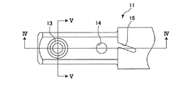
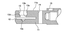
プランジャ10のブレード取付端部11は、先端側が高さb、幅cの断面略四角形状をなし、ブレード70の取付端部70Aが挿入されるブレード挿入部たるスリット12が、プランジャ10の先端面からブレードの長手方向に延びて形成される。スリット12は図5に示されるように、プランジャ10のブレード取付端部11の上下方向に貫通して形成される。また係止穴たる段付穴13が、スリット12に直角に交差しかつブレード70の側面に直角な方向に、ブレード取付端部11の外周面から延びてスリット12を越えて形成される。段付穴13は、ブレード70がスリット12に完全に挿入された状態で、ブレード70の係合穴70aと同芯となる位置に形成される。段付穴13は、大径部13aが外側に配置されてブレード取付部11の側面に開口し、中径部13bが内側に配置されて、スリット12に開口し、小径部13cがスリット12に関し中径部13bの反対側に形成される。これら大径部13a、中径部13b、小径部13cは互いに同軸である。なお小径部13cの先端の断面三角形状部は、ドリル加工時の刃先により穿設された部位である。更に、段付穴13の軸に平行な貫通穴14がスリット12の後方に形成されている。プランジャ10のブレード取付端部11の高さbは、ブレード70の取付端部70Aの高さaより僅かに小さい。また、断面略四角形部の後部には断面略円形部が設けられ、断面四角形部と断面円形部の境界に一端が開口する溝15が、断面円形部に形成されている。
【0027】
図6乃至図9は、ブレード70がプランジャ10に固定された状態のブレード着脱機構1を示す。ブレード着脱機構1は、上述したプランジャ10のブレード取付端部11と、係止部材たる係止ピン16と、第1弾性体たる捩りコイルバネ17と、第2弾性体たる圧縮コイルバネ18と、ノブ20と、ブレードホルダ30と、締結ボルト40とを有する。
【0028】
係止ピン16は、段付穴13内に進退可能に配設され、スリット12に挿入されたブレードの取付端部70Aに形成された係合穴70aに対して係合、離脱するためのものである。具体的には係止ピン16は、先端部から順に、第1円柱部16A、第1円柱部よりも直径が大きく段付穴13の中径部13bと略同径の第2円柱部16B、第2円柱部よりも直径が大きく、段付穴13の大径部13aと略同径の第3円柱部16Cを有し、第3円柱部16Cには後述するノブ20と当接する面が傾斜面をなす当接部16Dが設けられる。第1円柱部16Aは、ブレード70の係合穴70aに出没可能なサイズであり、ブレード70の厚さに応じて段付穴13の小径部13c内にも位置する。第1円柱部16Aと第2円柱部16Bとの界面は、係止ピン16がその先端方向に移動したときに、ブレード70の取付端部の側面を押圧するための段差面16Eをなす。また大径部13a内であって、第2円柱部16Bの外周面には、第2弾性体たる圧縮コイルバネ18が配設される。圧縮コイルバネ18の一端は、段付穴13の大径部13aと中径部13bとの界面の段差面13d(図4)に当接し、圧縮コイルバネ18の他端は、係止ピン16の第2円柱部16Bと第3円柱部16Cとの段差面に当接する。従って、係止ピン16は圧縮コイルバネ18により、段付穴13から離脱する方向に、即ち第1円柱部16Aがブレード係合穴70aから離脱する方向に付勢される。
【0029】
ノブ20は、プランジャ10の長手方向に直交する回動軸心14aを中心に回動可能に設けられ、この回動に伴い係止ピン16の当接部16Dに対する押圧力を変化させて係止ピン16の係合穴70aに対する進退を規制するために設けられる。ここで回動軸心14aは貫通穴14と同軸的であり、貫通穴14には締結ボルト40が貫通して設けられる。ノブ20は鋼材等の強度材で形成され、プランジャ10のブレード取付端部11の長手方向と直交する方向において、その外方に位置する。ノブ20は、回動基端部20Aと回動操作部20Bと係止ピン押圧部20Cとを備える。回動基端部20Aには締結ボルト40を挿通させるボルト挿通穴20aが形成されると共に、プランジャ10のブレード取付端部11との間に捩りコイルバネ装着室20bが画成される。即ち、第1弾性体たる捩りコイルバネ17はプランジャ10の長手方向と直交する方向においてノブ20の内方に位置してノブ20で覆われている。
【0030】
係止ピン押圧部20Cのブレード取付端部11に対向する面は傾斜面20cをなし、傾斜面20cは、係止ピン16の当接部16Dと常時当接可能に設けられている。回動操作部20Bは、プランジャ10のブレード取付端部11の側面から離間する方向に且つ回動軸心14aと平行に突設された突起部21を有する。ここで回動軸心14aと傾斜面20cと当接部16Dとの当接部位間の距離qは、回動軸心14aと突起部21の軸心間の距離pよりも小さく構成される。
【0031】
捩りコイルバネ17は締結ボルト40の軸部の周囲に配設される。捩りコイルバネ17の一端は、上述したプランジャのブレード取付端部11の溝15に係止され、他端はノブ20のバネ係止溝部20dに係止される。捩りコイルバネ17は、係止ピン16の第1円柱部16Aがブレードの係合穴70aに係止する方向に常時係止ピン16を付勢するために、傾斜面20cの当接部16Dに対する押圧力が増す方向(図8における矢印B方向)にノブ20を回動付勢しており、かつ捩りコイルバネ17の付勢力は圧縮コイルバネ18の付勢力よりも大きく設定される。回動操作部20Bを捩りコイルバネ17の付勢力に抗して締結ボルト40を中心として回動することにより、傾斜面20cが当接部16Dに対して移動し、よって傾斜面20cが当接部16Dに及ぼす付勢力が変化することにより、圧縮コイルバネ18で付勢されている係止ピン16の軸方向位置が変位可能となる。また切断作業中においては、捩りコイルバネ17の弾発力は、プランジャ10の往復運動方向とは直角方向の軸14aを中心として作用するため、切断作業時のプランジャ10の高速往復運動により生ずる加速度による影響は小さく、安定した弾発力を発揮することができる。
【0032】
ブレードホルダ30は、ブレード70の上下方向の切断荷重を支えることを主な機能とする。即ちセーバーソー本体51を被切断材に押し付けながら切断するためにブレード70の上下方向に荷重が発生するので、ブレードホルダ30はブレード70の取付端部70Aにおける上下方向の荷重を支える必要がある。また上述したように、ブレード70はその長手方向の往復運動のみならず、切り込み効率を高めるために僅かではあるが回動運動が伴われる。そのことにより上下方向荷重が強まるので、その荷重を支える必要がある。また被切断材に最も近接した部位にブレード着脱機構1が配置されているので、ブレードホルダ30は、切断作業時に被切断材が衝突したり噛み込んだりする危険性からブレード着脱機構内部を保護する機能と、被切断材の切断粉などがブレード着脱機構内部に進入するのを防ぐ防塵機能を発揮するものである。
【0033】
ブレードホルダ30は鋼材等の高強度材で形成されており、ノブ20とプランジャ10のブレード取付端部11の周囲に、これらの外形輪郭形状に合致する形状で配置される。ブレードホルダ30には、その側壁部30Aにノブ20の突起部21を貫通させノブ20の回動範囲を規制するための回動規制手段たる円弧状スロット31が形成されている。また側壁部30Aと対向する側壁部30Bには、締結ボルト40と螺合する雌ネジ部32が形成されている。よって、突起部21は、図6において捩りコイルバネ17によりスロット31の一端部に当接するまで図6の矢印B方向付勢され、スロット31の他端部に当接するまで図6の矢印A方向に回動操作できる。また、締結ボルト40の頭部と軸部との段部がノブ20の回動基端部20Aに当接し、締結ボルト40の先端雄ネジ部が、ブレードホルダ30の雌ネジ部32と螺合することで、構成部品全体がプランジャ10に組付けられる。換言すれば、単一の締結ボルト40による組立が可能となる。またこの組付け状態では、ブレードホルダ30の内面の平面部とプランジャ10のブレード取付端部11の外面の平面部とが、互いに角度の異なる複数の部位において当接関係にあり、また締結ボルト40がブレード取付端部11とブレードホルダ30とを固定しているので、ブレードホルダ30はプランジャ10に対し回転したり軸方向に移動することが防止される。更に、上壁部30Cと下壁部30Dの内面間の距離c(図8)は、上述したブレード70の取付端部70Aの上下面間の距離aに等しく、よって、ブレードの上下方向の加重が適切にブレードホルダ30に支持される。
【0034】
ノブ20の突起部21に着脱可能にノブカバー22が被冠されている。ノブカバー22は、ノブ20よりも熱伝達率が低くまた変形可能な樹脂又は弾性材料にて形成されると共に、円弧状スロット31を覆うためのフランジ部23が設けられている。ノブカバー22は突起部21よりも外形が大きいので、直接突起部をつかむことに比べてノブ20の操作性が向上できる。また、切断作業により、ブレード70に発生した摩擦熱が金属製のノブ20にも伝達されるが、熱伝達率の低いノブカバー22が突起部21に被冠されているので、ノブ20操作時に高温になったノブ20に直接触れることがない。更に、フランジ部23によって円弧状スロット31内に切削屑や粉塵が入り込むのを防止できる。またノブカバー22は突起部21に着脱可能であるので、ノブカバー22を突起部21から取外して円弧状スロット31内を清掃することができる。更にフランジ部23によって、ノブカバー22全体のサイズが大きくなるので、高温となった部材へ使用者の指などが接触してしまう可能性を一層減らすことができる。
【0035】
図10(A)はノブ20を傾斜面20c側からみた平面図であり、締結ボルト40の頭部に当接する平面部から直角にリブ20Dが設けられて、捩りコイルバネ17の装着室20bが提供される。また、平面部には上述したバネ係止溝部20dが刻設されている。また傾斜面20cは、ブレードの取付端部70Aの側面と平行な基準線Xに対して角度θをなす。このようにノブ20の係止ピン16に当接する面が傾斜面20cであるので、くさび効果が発揮され、ノブ20の回動操作による傾斜面20cの移動によって、より確実に係止ピン16に押圧力を作用することができる。また傾斜面20cの傾斜角度θを適宜変更すれば、ノブ20の回動量に対応する係止ピン16の変位量を簡単に変更することができる。
【0036】
次にブレード着脱機構1によるプランジャ10に対するブレード70の着脱操作について説明する。なお図1の状態おいては、ブレード着脱機構1のノブカバー22は、セーバソー本体51内部にあるため、ノブカバー22に指を近づけることができない。この場合にはスイッチ58を操作しプランジャ10を駆動してノブカバー22をセーバソー本体51外に位置させればよい。また、ノブカバー22が完全にセーバーソー本体51の外部に位置していない場合でも、レシプロプレート69の揺動軸部69Aが図1とは反対に前傾している状態であれば、ブレード70をつかんでブレード70を前方に移動させブレード着脱機構1を前方に引き出すことが可能である。
【0037】
ブレード着脱機構1にブレード70が取付けられていない状態では、係止ピン16の先端の第1円柱部16Aは、捩りコイルバネ17の付勢力によりプランジャ10のブレード取付端部11のスリット12内部に突出しているため、新たなブレード70を固定できる位置までブレード70の取付端部70Aをスリット12内に挿入することはできない。そこで図6の矢印A方向にノブカバー22を回動操作すると、ノブ20の突起部21が円弧状スロット31内を移動してスロット31の一端に当接するまで、ノブ20は捩りコイルバネ17の付勢力に抗してプランジャ10のブレード取付端部11の貫通穴14の軸心14aを中心に回動する。この回動により、ノブ20の傾斜面20cは係止ピン16の当接部16Dに対して図8の矢印A方向に移動していくので、ノブ20による係止ピン16への押圧が徐々に解放される。係止ピン16は圧縮コイルバネ18の付勢力により、スリット12面から外側方向に力を受けているので、係止ピン16の当接部16Dがノブ20の傾斜面20cと接触しながら、係止ピン16はプランジャ10のブレード取付端部11の側面外方に、即ちスリット12から後退する方向に移動する。
【0038】
ノブカバー22をA方向に回動操作する場合に、図7に示されるように、距離pは距離qよりも大きく設定されているので、貫通穴14の軸心14aを中心として矢印Aの向きに荷重F1を作用させると、軸心14dから距離qにある係止ピン16の軸心に作用する力を荷重F2とすれば、てこの原理より、F1×p=F2×qの関係式が成立する。荷重F2はF2=p/q×F1であるから、p>qとしたことにより、F1<F2となる。即ち少ない操作力F1で、係止ピン16に大きな力を作用させることができ、操作性を向上させることができる。
【0039】
図11乃至図14は、ノブ20が矢印A方向の回動限界位置に達した状態を示している。この状態では、係止ピン16の第1円柱係止部16Aは完全にスリット16面から後退し、新たなブレード70の装着が可能な状態となる。
【0040】
新たなブレード70を固定する場合には、捩りコイルバネ17の付勢力に抗してノブ20が矢印A方向の回動限界位置に達した状態を維持しつつ、新たなブレード70の取付端部70Aをスリット12内に挿入する。このとき、第1円柱部16Aはスリット12内に突出していないので、ブレードの取付端部70Aの後端面が第1円柱部16Aに衝突することはない。ブレード70の挿入後にノブカバー22を離すと、捩りコイルバネ17の付勢力により、ノブ20は、図11、図14の矢印B方向に自動的に回動する。この回動に伴い、ノブ20の傾斜面20cが図13の矢印B方向に移動してゆき、係止ピン16は段付穴13の軸方向に沿ってスリット12方向へ押圧される。そしてブレードの係合穴70aに係止ピン16の第1円柱部16Aが挿入され、同時に、ブレード70の取付端部70Aの側面は段差面16Eにより押圧されて、図7、図8に示されるように、スリット12の一方の壁面と段差面16Eとの間に挟持され固定される。圧縮コイルバネ18の圧縮力は、小さな係止ピン16をその軸方向に移動させるための弾発力があれば十分であり、捩りコイルバネ17の弾発力に比べて十分小さく設定できる。なお、図7や図12によれば、スリット12の幅がブレードの取付端部70Aの厚さよりも大きく隙間があるが、これは様々な厚さのブレードを装着できるようにするためである。厚いブレードが装着された場合には、第1円柱部16Aの先端は、ブレードの係合穴70aの途中までしか係止されないが、係止関係がありまた上述の挟持関係がある限り、厚いブレードでも確実に固定できる。
【0041】
装着されていたブレード70を取外す場合には、ブレードの装着の場合と同様に、ノブカバー22を図6の矢印A方向に操作することにより、ノブ20による係止ピン16への押圧が解放され、係止ピン16は圧縮コイルバネ18の付勢力により、スリット16面から外側方向に移動し、係止ピン16の第1円柱部16Aがブレード70の取付端部70Aの係合穴70aから離脱し、ブレード70の取外しが可能となる。このように、プランジャ10のブレード取付端部11の段付穴13の内部に、係止ピン16を後退させる方向に付勢する圧縮コイルばね18を設け、ブレード70の取外し時に係止ピン16が自動的にブレードの係合穴70aから離脱できる構成であるので、プランジャ10の先端を下方に向けるだけで、ブレード70や折損したブレードの破片を自重により容易にスリット12から脱落させることができ、ブレードやその破片の取外しが簡単に行える。
【0042】
第1の実施の形態におけるノブの変形例について図15に基づき説明する。図15に示されるノブ20Xは傾斜面を除き第1の実施の形態のノブ20と同様である。ノブ20Xには、係止ピン16の当接部16Dと当接する複数(変形例では2個)の傾斜面20Xc1、20Xc2が隣あって形成されている。第1の傾斜面20Xc1は、ブレードの取付端部70Aの側面と平行な基準線Xに対して角度θ1をなし、第2の傾斜面20Xc2は基準線Xに対して角度θ1より大きい角度θ2をなす。
【0043】
異なる角度の傾斜面20Xc1、20Xc2とすることで、ブレード70の固定のためには、傾斜角度の小さい傾斜面20Xc1により行うことで、捩りコイルバネ17のバネ荷重を小さくできる。また傾斜角度の大きい傾斜面20Xc2が係止ピン16に作用することにより、ノブ20の少ない回動量でブレード取外し時の係止ピン16の後退量を大きく設定でき、操作性が向上する。なお2つの傾斜面とすることに代えて、曲面にしたり、互いに傾斜角度の異なるより多数の傾斜面を形成することによっても、係止ピン16の軸方向の移動の態様を適宜設定できる。
【0044】
本発明の第2の実施の形態によるブレード着脱機構101について図16乃至図19に基づき説明する。第1の実施の形態では、ブレードホルダ30のプランジャのブレード取付端部11への固定と、ノブ20の回転軸の支持とが単一の締結ボルト40によって行なれ、部品点数の減少に寄与する構成である。一方、第2の実施の形態では、第1の実施の形態における締結ボルト40に相当するピン140が、ノブ120の回動軸としての機能にとどまり、第1の実施の形態と同様に、捩りコイルバネ17を同軸的に支持している。ピン140はプランジャのブレード取付端部111を貫通し、先端側には環状の止め輪溝が形成され、止め輪溝に止め輪141が嵌合されて、ピン140が取付端部111に固定される。更に、ボルト142がピン140とは別に設けられ、ブレードホルダ130及びプランジャのブレード取付端部111には、ボルト142と螺合し段付穴113と同軸上の雌ネジ部130a、111aがそれぞれ形成される。ボルト142を雌ネジ130a,111aに螺合することにより、ブレードホルダ130はプランジャのブレード取付端部111に固定される。
【0045】
本発明の第3の実施の形態によるブレード着脱機構201について図20、図21に基づき説明する。第3の実施の形態では、ブレードホルダ130をボルト142によってプランジャのブレード取付端部211に固定している点で第2の実施の形態と同様であるが、プランジャのブレード取付端部211を貫通する雌ネジ211aを形成し、第2の実施の形態のピン140に代えて雌ネジ211aに螺合するボルト240を設けた点で、第2の実施の形態と相違する。係る構成によれば、第2の実施の形態の止め輪141を省略することができる。更に、第3の実施の形態においては、係止ピン116の当接部116Dの当接面全体を、ノブ20の傾斜面20cの傾斜角度と同一角度の面に形成されている。従って、ノブ20の傾斜面20cと係止ピンの傾斜面116Dとを面で接触させることができ、両者の接触面積を大きくして動作を安定させると共に、偏摩耗を防止することができる。
【0046】
本発明によるブレード着脱機構は、上述した実施の形態に限定されず、特許請求の範囲に記載された範囲で、種々の変形が可能である。例えば、第3の実施の形態における傾斜面116Dを、第1、第2の実施の形態における係止ピン16に適用してもよい。
【0047】
また、上述した実施の形態では、プランジャのブレード取付端部11,111、211を一体の部材により形成し、そこにスリット12、112を形成しているが、取付端部を多数の部品で構成し、部品を組付けたときにブレード挿入部たるスリット相当部が提供されるようにしてもよい。更に上述した実施の形態では、回動軸心14aと突起部の軸心21との間の距離pは、回動軸心とノブ20が係止ピン16に及ぼす作用点との間の距離qよりも長く設定しているが、操作性に支障がない限りはp=qとしてもよい。
【0048】
【発明の効果】
請求項1記載のセーバソーによれば、ノブを回動させるだけの簡単な操作により、ブレードに触れることなくプランジャに対するブレードの着脱が可能となり、着脱作業性を向上できる。また、係止部材とノブと第1弾性体のみで、係止部材の移動が規制でき、部品点数が少なく組立性に優れた機構が実現できる。
【0049】
請求項2記載のセーバソーによれば、プランジャを1体物で構成し、プランジャに機械加工等でスリットを形成することで、簡単にブレード挿入部を提供することができる。
【0050】
請求項3記載のセーバソーによれば、該ノブを所定方向に回動させたときに、係止部材を強制的に係合穴から離脱させることができる。
【0051】
請求項4記載のセーバソーによれば、捩りコイルバネの弾発力は、プランジャの往復運動方向とは直角方向の回動軸心を中心として作用するため、切断作業時のプランジャの高速往復運動により生ずる加速度による影響が小さく、安定した弾発力を発揮することができる。
【0052】
請求項5記載のセーバソーによれば、第1弾性体はノブにより覆われているので、第1弾性体を捩りコイルバネなどで構成したときに、切断屑が捩りバネの螺旋部に付着することが防止でき、第1弾性体の防塵性が確保できる。
【0053】
請求項6記載のセーバソーによれば、突起に指を掛けるだけで、簡単にノブを回動操作できる。
【0054】
請求項7記載のセーバソーによれば、回動軸心が支点となり、突起の軸心が力点となるが、力点に及ぼす力(突起を回動操作する力)と同等又はそれ以上の力が作用点に作用するので、少ない操作力で係止部材を確実に変位させることができる。
【0055】
請求項8記載のセーバソーによれば、ブレードホルダにより、ノブとプランジャとが所定の位置関係に確保できると共に、ブレードの取付端部の上下面がブレードホルダの内周面に固定保持されて、ブレードの上下方向のガタツキを防止できる。また、ノブがブレードホルダによって保護され、ノブに対する防塵効果が期待できる。
【0056】
請求項9記載のセーバソーによれば、ノブの係止部材に当接する面が傾斜面であるので、くさび効果が発揮され、ノブの回動操作による傾斜面の移動によって確実に係止部材に押圧力を作用することができる。
【0057】
請求項10記載のセーバソーによれば、ノブの傾斜面と係止部材の当接面とを面で接触させることができ、両者の接触面積を大きくして動作を安定させることができる。
【0058】
請求項11記載のセーバソーによれば、ノブの回動位置に応じた傾斜面の係止部材に対する押圧力を、傾斜面の傾斜角度に応じて変更でき、ブレード着脱機構自体の設計の自由度を高めることができる。
【0059】
請求項12記載のセーバソーによれば、例えば、第1傾斜面の傾斜を鉛直に近い傾斜とすることで、傾斜面は効果的に係止部材を押圧して係止部材はブレード取付端部を確実に押圧でき、第2傾斜面の傾斜を第1傾斜面の傾斜角度より大きく水平に近い傾斜とすることで、係止部材がブレード取付端部を押圧する必要がない場合に、ノブの僅かな回動ストロークでも、第2傾斜面の係止部材に対する押圧を解除できる。
【0060】
請求項13記載のセーバソーによれば、単一の締結部材によって、ノブと第1弾性部材とプランジャに対する支持や締結が実現でき、部品点数を減少することができる。
【0061】
請求項14記載のセーバソーによれば、ノブカバーは突起そのものよりもサイズが大きいので、ノブの操作性が向上できる。また、切断作業により、ブレードに発生した摩擦熱がノブにも伝達されるが、熱伝達率の低いノブカバーが突起に被冠されているので、高温になったノブに直接触れることがない。
【0062】
請求項15記載のセーバソーによれば、フランジ部によって長穴内に切削屑や粉塵が入り込むのを防止できる。また該ノブカバーを着脱可能としているので、ノブカバーを突起から取外して長穴内を清掃することができる。更にフランジ部によって、ノブカバー全体のサイズが大きくなるので、高温となった部材へ使用者の指などが接触してしまう可能性を一層減らすことができる。
【0063】
請求項16記載のセーバソーによれば、突起に対するノブカバーの着脱を一層容易に行うことができる。
【図面の簡単な説明】
【図1】 本発明の第1の実施の形態によるブレード着脱機構を備えたセーバソーを示す長手方向縦断面図。
【図2】 本発明のセーバソーに採用されるブレードの一例を示す側面図。
【図3】 本発明の第1の実施の形態によるセーバソーのブレード着脱機構をなすプランジャのブレード取付端部を示す側面図。
【図4】 図3のIV―IV線に沿った断面図。
【図5】 図3のV−V線に沿った断面図。
【図6】 本発明の第1の実施の形態によるセーバソーのブレード着脱機構を示す側面図であってブレードを固定した状態を示す図。
【図7】 図6のVII−VII線に沿った断面図。
【図8】 図6のVIII−VIII線に沿った断面図。
【図9】 図7のIX−IX線に沿った断面図。
【図10】 本発明の第1の実施の形態によるセーバソーのブレード着脱機構の構成部品であるノブを示し(A)はその底面図、(B)は(A)のXb―Xb線に沿った断面図。
【図11】 本発明の第1の実施の形態によるセーバソーのブレード着脱機構を示す側面図であって、ブレードを取外す過程の状態を示す図。
【図12】 図11のXII−XII線に沿った断面図。
【図13】 図11のXIII−XIII線に沿った断面図。
【図14】 図12のXIV−XIV線に沿った断面図。
【図15】 本発明の第1の実施の形態によるセーバソーのブレード着脱機構の構成部品であるノブの変形例を示し(A)はその底面図、(B)は(A)のXVb―XVb線に沿った断面図。
【図16】 本発明の第2の実施の形態によるセーバソーのブレード着脱機構を示す側面図。
【図17】 図16の右側面図。
【図18】 図16のXVIII−XVIII線に沿った断面図。
【図19】 図16のXIX−XIX線に沿った断面図。
【図20】 本発明の第3の実施の形態によるセーバソーのブレード着脱機構を示す図7、図18に対応する断面図。
【図21】 本発明の第3の実施の形態によるセーバソーのブレード着脱機構を示す図8、図19に対応する断面図。
【符号の説明】
10 プランジャ
11、111、211 ブレード取付端部
12、112 スリット
13、113 段付穴
14 貫通穴
14a 回動軸心
16、116 係止部材たる係止ピン
16D、116D 当接部
16E 段差面
17 第1弾性体たる捩りコイルバネ
18 第2弾性体たる圧縮コイルバネ
20、20X ノブ
20c、120c 20Xc1、20Xc2 傾斜面
21 突起部
22 ノブカバー
23 フランジ部
30、130 ブレードホルダ
31 円弧状スロット
40 締結ボルト
50 セーバーソー
51 セーバーソー本体
70 ブレード
70A 取付端部
70a 係合穴[0001]
BACKGROUND OF THE INVENTION
The present invention Saver saw, a reciprocating cutting tool driven by an electric motor In particular, Saver saw with blade attachment / detachment mechanism About.
[0002]
[Prior art]
An electric saver saw is used to cut materials to be cut such as wood, steel, and pipes in the construction, renovation, and demolition of houses and buildings. As is well known, saversaw reciprocates a reciprocating shaft (hereinafter referred to as a plunger) with a linear saw blade (hereinafter referred to as a blade) in a tool body along a revolution path or a linear path, and reciprocates a blade outside the tool body. Move the material to be cut.
[0003]
Generally, the reciprocating amount of the plunger (hereinafter referred to as stroke amount) is about 20 mm for a small one and about 32 mm for a large one. For this reason, in the actual cutting operation, since the blade portion of the blade acts on the material to be cut locally within the stroke amount range, the blade is consumed heavily, and it is necessary to frequently replace the blade particularly in the cutting operation of the steel material. there were. In addition, since cutting is performed by reciprocating a slender blade at high speed, the plunger mounting end of the blade may break due to the reaction force generated during normal cutting. In such a case, the blade needs to be replaced. I was trying.
[0004]
In order to attach and detach the blade to and from the plunger, there is provided a blade holder that has a locking hole formed at the plunger mounting end of the blade and a projection that can be inserted into the locking hole. The blade holder is attached to and detached from the plunger of the blade by tightening or loosening the set screw using a tool such as a wrench. However, this configuration has a problem that it takes time to attach and detach, and the work efficiency does not increase, and a tool such as a wrench must always be carried, and the blade cannot be attached or detached if the tool is lost.
[0005]
U.S. Pat. Nos. 5,443,276, 5,557,071, and 5647133 describe a toolless blade attachment / detachment mechanism that enables attachment / detachment of a blade without the need of a tool such as a wrench. Among these gazettes, the toolless attachment / detachment mechanism in US Pat. Nos. 5,443,276, 5,557,071, and 5647133 has a steel ball or a member in which a tip protrusion is formed in a conical shape as a movable locking member. Insert the tip of the stop member into the engagement hole of the blade, hold the blade by pressing the movable locking member against the blade with a lever or rotating ring provided on the saver saw body, and operate the lever or rotating ring, etc. Thus, the blade can be removed by creating a space where the movable locking member can be detached from the engagement hole of the blade.
[0006]
[Problems to be solved by the invention]
In any of the attachment / detachment mechanisms described in the above-mentioned publications, in order to finally disengage the movable locking member from the engagement hole of the blade, some movement must be given to the blade. It was necessary to operate while holding. In addition, when the blade breaks from the plunger mounting base, the blade cannot be directly operated with a fingertip, so that a great deal of labor is required to remove the blade remaining in the plunger.
[0007]
Further, in the blade attaching / detaching mechanism described in US Pat. Nos. 5,443,276 and 5,647,133, odd-shaped parts having complicated shapes are used, and these parts are exposed to the outside. For this reason, if the blade is sandwiched or collides with the material to be cut during the cutting operation, the blade attaching / detaching mechanism itself is liable to be damaged, and there is a problem of durability.
[0008]
Therefore, the present invention eliminates the disadvantages of the conventional blade attaching / detaching mechanism described above, can easily fix and remove the blade, and has excellent durability. Saver saw with blade attachment / detachment mechanism The purpose is to provide.
[0009]
[Means for Solving the Problems]
In order to achieve the above-mentioned object, the present invention has a blade insertion portion extending along a substantially reciprocating direction of the blade and a locking hole formed orthogonal to the blade insertion portion at the tip portion. A plunger that is driven to reciprocate in a substantially longitudinal direction, and a locking member that is disposed so as to be able to advance and retreat in the locking hole, and that engages with an engagement hole formed in a mounting end portion of the blade inserted into the blade insertion portion. And at the distal end portion of the plunger is provided so as to be rotatable around a rotation axis perpendicular to the longitudinal direction of the plunger, and the advancement / retraction of the locking member with respect to the engagement hole is regulated with the rotation. A knob and a first elastic body that biases the rotation of the knob in a direction in which the locking member enters the engagement hole; The pivot axis extends to one end of the knob, The knob The other end of Is the longitudinal direction of the plunger And the direction in which the pivot axis extends A saver saw is provided that is perpendicular to the direction.
[0010]
Here, it is preferable that the blade insertion portion is constituted by a slit extending from the one end surface of the plunger in the longitudinal direction of the plunger and penetrating in the vertical direction of the plunger.
[0011]
Also, a second elastic body having a biasing force smaller than the biasing force of the first elastic body is disposed in the locking hole in order to bias the locking member in the direction of separating from the engagement hole. It is preferable.
[0012]
Further, the first elastic body is constituted by a torsion coil spring supported around the rotation axis perpendicular to the longitudinal direction of the plunger, and one end of the torsion coil spring is locked to the knob, The other end is preferably configured to be locked to the plunger.
[0013]
Further, the knob is located outward of the plunger in a direction perpendicular to the longitudinal direction of the plunger, and the first elastic body is located inward of the knob in a direction perpendicular to the longitudinal direction of the plunger. Preferably it is covered with a knob. In this case, it is preferable that the knob is provided with a protrusion for performing a rotation operation in a direction away from the plunger and in parallel with the rotation axis. The distance between the pivot axis and the projection axis is equal to or longer than the distance between the pivot axis and the point of action of the knob on the locking member. Is preferred. The protrusion of the knob is preferably covered with a knob cover made of a material having a lower heat transfer coefficient than the knob. In this case, a blade holder that matches the outer contour shape of the knob and the plunger is provided around the knob and the plunger, and the blade holder is provided for restricting the rotation range of the protrusion. It is preferable that a long hole that penetrates the protrusion is formed, and the knob cover is provided with a flange portion that is detachable from the protrusion and covers the long hole. In this case, the knob cover is preferably made of an elastically deformable resin or elastic material.
[0014]
Further, as described above, when the blade insertion portion is a slit extending in the longitudinal direction of the plunger from the one end surface of the plunger and penetrating in the vertical direction of the plunger, the knob and the plunger are surrounded by the knob. And a blade holder that conforms to the outer contour shape of the plunger is provided. The blade holder is formed with a rotation restricting means for restricting the rotation range of the protrusion and the inner peripheral surface of the blade holder. Is preferably a structure for closing the upper and lower openings of the slit. In this case, the knob and the first elastic member are supported by the plunger by a single fastening member concentric with the rotational axis, and the blade holder is fastened to the plunger by the fastening member. Is preferred.
[0015]
Further, the knob is provided with an inclined surface that comes into contact with the locking member, and when the knob is rotated, the inclined surface moves with respect to the locking member, so that the locking member moves forward and backward with respect to the engagement hole. It is preferable that the structure regulates the above. In this case, the locking member has a contact surface that contacts the inclined surface of the knob, and the corresponding contact surface is inclined at substantially the same angle as the inclined angle of the inclined surface of the knob. preferable.
[0016]
Furthermore, it is preferable that the inclined surface of the knob has a plurality of inclined surfaces with different inclination angles arranged in succession. In this case, the plurality of inclined surfaces of the knob have at least a first inclined surface and a second inclined surface, and when the first inclined surface is in contact with the locking member, When the release of the pressing is performed and the second inclined surface is in contact with the locking member, it is preferable that only the cancellation of the pressing of the locking member is performed.
[0017]
DETAILED DESCRIPTION OF THE INVENTION
A saver saw 50 provided with a blade attaching / detaching mechanism 1 according to an embodiment of the present invention will be described with reference to FIG. In FIG. 1, the left side is assumed to be the front and the right side is assumed to be the rear.
[0018]
A
[0019]
The
[0020]
A
[0021]
The
[0022]
A bearing
[0023]
The
[0024]
A base 76 that stabilizes the saver saw
[0025]
As shown in FIG. 2, the rear end of the
[0026]
The
[0027]
6 to 9 show the blade attaching / detaching mechanism 1 in a state where the
[0028]
The locking
[0029]
The
[0030]
The surface of the locking
[0031]
The
[0032]
The main function of the
[0033]
The
[0034]
A
[0035]
FIG. 10A is a plan view of the
[0036]
Next, the attachment / detachment operation of the
[0037]
In a state where the
[0038]
When the
[0039]
11 to 14 show a state in which the
[0040]
When the
[0041]
When removing the attached
[0042]
A modification of the knob in the first embodiment will be described with reference to FIG. The
[0043]
By using the inclined surfaces 20Xc1 and 20Xc2 having different angles, the
[0044]
A blade attaching /
[0045]
A blade attaching /
[0046]
The blade attaching / detaching mechanism according to the present invention is not limited to the above-described embodiment, and various modifications can be made within the scope described in the claims. For example, the
[0047]
Moreover, in embodiment mentioned above, although the blade attachment end part 11,111,211 of a plunger is formed with an integral member and the
[0048]
【The invention's effect】
Claim 1 Saver saw According to this, the blade can be attached to and detached from the plunger without touching the blade by a simple operation by simply rotating the knob, and the detachment workability can be improved. Further, the movement of the locking member can be restricted only by the locking member, the knob, and the first elastic body, and a mechanism with a small number of parts and excellent assembly can be realized.
[0049]
Claim 2 Saver saw According to the above, it is possible to easily provide the blade insertion portion by configuring the plunger as a single body and forming a slit in the plunger by machining or the like.
[0050]
Claim 3 Saver saw Accordingly, the locking member can be forcibly detached from the engagement hole when the knob is rotated in a predetermined direction.
[0051]
Claim 4 Saver saw According to the present invention, the elastic force of the torsion coil spring acts around the rotation axis perpendicular to the reciprocating direction of the plunger, and therefore is less affected by the acceleration caused by the high-speed reciprocating motion of the plunger during the cutting operation. Stable elasticity can be demonstrated.
[0052]
Claim 5 Saver saw Since the first elastic body is covered with the knob, when the first elastic body is constituted by a torsion coil spring or the like, it is possible to prevent cutting waste from adhering to the spiral portion of the torsion spring, and the first elasticity The body can be protected against dust.
[0053]
Claim 6 Saver saw According to this, the knob can be easily rotated by simply placing a finger on the protrusion.
[0054]
Claim 7 Saver saw According to the above, the pivot axis serves as a fulcrum, and the projection axis serves as a power point. However, since a force equal to or greater than the force exerted on the force point (force for rotating the projection) acts on the action point, The locking member can be reliably displaced with a small operating force.
[0055]
Claim 8 Saver saw According to the blade holder, the knob and the plunger can be secured in a predetermined positional relationship, and the upper and lower surfaces of the attachment end portion of the blade are fixed and held on the inner peripheral surface of the blade holder, so that the vertical movement of the blade is prevented. Can be prevented. Further, the knob is protected by the blade holder, and a dustproof effect on the knob can be expected.
[0056]
Claim 9 Saver saw According to the present invention, since the surface that contacts the locking member of the knob is an inclined surface, the wedge effect is exerted, and the pressing force can be reliably applied to the locking member by the movement of the inclined surface by the turning operation of the knob. it can.
[0057]
[0058]
[0059]
[0060]
[0061]
[0062]
[0063]
[Brief description of the drawings]
FIG. 1 shows a blade attaching / detaching mechanism according to a first embodiment of the present invention. Prepared The longitudinal direction longitudinal cross-sectional view which shows a saver saw.
FIG. 2 of the present invention Saver saw The side view which shows an example of the braid | blade employ | adopted.
FIG. 3 according to a first embodiment of the present invention Saver saw The side view which shows the blade attachment end part of the plunger which makes | forms a blade attachment / detachment mechanism.
4 is a cross-sectional view taken along the line IV-IV in FIG. 3;
5 is a cross-sectional view taken along the line VV in FIG. 3. FIG.
FIG. 6 shows the first embodiment of the present invention. Saver saw It is a side view which shows a blade attachment / detachment mechanism, and is a figure which shows the state which fixed the blade.
7 is a sectional view taken along line VII-VII in FIG. 6;
8 is a cross-sectional view taken along line VIII-VIII in FIG.
9 is a sectional view taken along line IX-IX in FIG.
FIG. 10 shows the first embodiment of the present invention. Saver saw The knob which is a component of a blade attachment / detachment mechanism is shown, (A) is the bottom view, (B) is sectional drawing along the Xb-Xb line | wire of (A).
FIG. 11 shows the first embodiment of the present invention. Saver saw It is a side view which shows a blade attachment / detachment mechanism, Comprising: The figure which shows the state in the process of removing a blade.
12 is a sectional view taken along line XII-XII in FIG.
13 is a cross-sectional view taken along line XIII-XIII in FIG.
14 is a cross-sectional view taken along line XIV-XIV in FIG.
FIG. 15 shows the first embodiment of the present invention. Saver saw The modification of the knob which is a component of a blade attachment / detachment mechanism is shown, (A) is the bottom view, (B) is sectional drawing which followed the XVb-XVb line | wire of (A).
FIG. 16 shows a second embodiment of the present invention Saver saw The side view which shows a blade attachment / detachment mechanism.
FIG. 17 is a right side view of FIG.
18 is a cross-sectional view taken along line XVIII-XVIII in FIG.
19 is a sectional view taken along line XIX-XIX in FIG.
FIG. 20 shows a third embodiment according to the present invention. Saver saw Sectional drawing corresponding to FIG. 7, FIG. 18 which shows a blade attachment / detachment mechanism.
FIG. 21 shows a third embodiment according to the present invention. Saver saw Sectional drawing corresponding to FIG. 8, FIG. 19 which shows a blade attachment / detachment mechanism.
[Explanation of symbols]
10 Plunger
11, 111, 211 Blade mounting end
12, 112 slit
13, 113 Stepped hole
14 Through hole
14a Center of rotation
16, 116 A locking pin as a locking member
16D, 116D contact part
16E Stepped surface
17 Torsion coil spring as first elastic body
18 Compression coil spring as second elastic body
20, 20X knob
20c, 120c 20Xc1, 20Xc2 Inclined surface
21 Protrusion
22 Knob cover
23 Flange
30, 130 Blade holder
31 Circular slot
40 Fastening bolt
50 saver saw
51 Saver saw body
70 blades
70A Mounting end
70a engagement hole
Claims (16)
該係止穴内に進退可能に配設され、該ブレード挿入部に挿入されたブレードの取付端部に形成された係合穴に係合する係止部材と、
該プランジャの先端部において、該プランジャの長手方向に直交する回動軸心を中心に回動可能に設けられ、該回動に伴い該係止部材の該係合穴に対する進退を規制するノブと、
該係止部材が該係合穴に侵入する方向に該ノブの回動を付勢する第1弾性体とが設けられ、
該ノブの一端側に該回動軸心が延び、該ノブの他端側の回動方向は該プランジャの長手方向と該回動軸心が延びる方向とに直交する方向であることを特徴とするセーバソー。A plunger having a blade insertion portion extending along the substantially reciprocating direction of the blade and a locking hole formed orthogonal to the blade insertion portion at the tip, and driven to reciprocate substantially in the longitudinal direction;
A locking member that is movably disposed in the locking hole and engages with an engagement hole formed in an attachment end of the blade inserted into the blade insertion portion;
A knob provided at the distal end of the plunger so as to be rotatable about a rotation axis perpendicular to the longitudinal direction of the plunger, and regulating the advancement and retraction of the locking member with respect to the engagement hole along with the rotation; ,
A first elastic body that biases the rotation of the knob in a direction in which the locking member enters the engagement hole;
The rotation axis extends to one end of the knob, and the rotation direction of the other end of the knob is a direction orthogonal to the longitudinal direction of the plunger and the direction in which the rotation axis extends. Saver saw.
Priority Applications (2)
| Application Number | Priority Date | Filing Date | Title |
|---|---|---|---|
| JP2002005495A JP4166982B2 (en) | 2002-01-15 | 2002-01-15 | Saver saw |
| US10/338,674 US6893026B2 (en) | 2002-01-15 | 2003-01-09 | Blade attaching and detaching mechanism |
Applications Claiming Priority (1)
| Application Number | Priority Date | Filing Date | Title |
|---|---|---|---|
| JP2002005495A JP4166982B2 (en) | 2002-01-15 | 2002-01-15 | Saver saw |
Publications (3)
| Publication Number | Publication Date |
|---|---|
| JP2003205423A JP2003205423A (en) | 2003-07-22 |
| JP2003205423A5 JP2003205423A5 (en) | 2005-07-07 |
| JP4166982B2 true JP4166982B2 (en) | 2008-10-15 |
Family
ID=19191114
Family Applications (1)
| Application Number | Title | Priority Date | Filing Date |
|---|---|---|---|
| JP2002005495A Expired - Fee Related JP4166982B2 (en) | 2002-01-15 | 2002-01-15 | Saver saw |
Country Status (2)
| Country | Link |
|---|---|
| US (1) | US6893026B2 (en) |
| JP (1) | JP4166982B2 (en) |
Families Citing this family (19)
| Publication number | Priority date | Publication date | Assignee | Title |
|---|---|---|---|---|
| GB2407532A (en) * | 2003-10-28 | 2005-05-04 | Black & Decker Inc | Clamp assembly for removably mounting a working member |
| US20050092156A1 (en) * | 2003-10-29 | 2005-05-05 | Credo Technology Corporation | Scroll collar for reciprocating saw |
| US7437824B2 (en) * | 2005-06-27 | 2008-10-21 | Black & Decker Inc. | Adjustable shoe assembly for a reciprocating saw |
| GB2431613A (en) * | 2005-10-28 | 2007-05-02 | Black & Decker Inc | Blade clamp for a reciprocating saw |
| US8813373B2 (en) | 2007-09-14 | 2014-08-26 | Milwaukee Electric Tool Corporation | Blade clamp mechanism |
| US8230607B2 (en) | 2008-05-09 | 2012-07-31 | Milwaukee Electric Tool Corporation | Keyless blade clamp for a power tool |
| JP5201469B2 (en) * | 2008-09-29 | 2013-06-05 | 日立工機株式会社 | Saver saw |
| CN202878425U (en) * | 2009-02-05 | 2013-04-17 | 米沃奇电动工具公司 | Handsaw and saw blade used together with the handsaw |
| US8261456B2 (en) * | 2009-06-23 | 2012-09-11 | Milwaukee Electric Tool Corporation | Hand saw |
| JP5489070B2 (en) * | 2010-02-10 | 2014-05-14 | 日立工機株式会社 | Reciprocating tool |
| US8292150B2 (en) | 2010-11-02 | 2012-10-23 | Tyco Healthcare Group Lp | Adapter for powered surgical devices |
| US9156097B2 (en) * | 2012-03-20 | 2015-10-13 | Milwaukee Electric Tool Corporation | Reciprocating saw blade clamp |
| US10661365B2 (en) * | 2016-10-11 | 2020-05-26 | Stanley Black & Decker, Inc. | Folding multi saw |
| EP3538310B1 (en) * | 2016-11-10 | 2023-08-16 | Milwaukee Electric Tool Corporation | Blade clamp for a reciprocating power tool and power tool |
| KR102631964B1 (en) * | 2016-11-23 | 2024-01-31 | 엘지이노텍 주식회사 | Method, Apparatus, System, Program and Recording Medium for Analyzing Image using Vehicle Driving Information |
| JP6857536B2 (en) * | 2017-04-06 | 2021-04-14 | 株式会社やまびこ | Portable cutting machine |
| WO2019241010A1 (en) | 2018-06-14 | 2019-12-19 | Milwaukee Electric Tool Corporation | Blade clamp for reciprocating saw |
| US20240051044A1 (en) * | 2022-08-11 | 2024-02-15 | Techtronic Cordless Gp | Hacksaw |
| CN116038023B (en) * | 2023-02-14 | 2024-03-19 | 乐清市乾丰工具有限公司 | Multifunctional hand-held tool |
Family Cites Families (11)
| Publication number | Priority date | Publication date | Assignee | Title |
|---|---|---|---|---|
| US316031A (en) * | 1885-04-21 | Connection for windmill and piston rods | ||
| US1179476A (en) * | 1914-06-29 | 1916-04-18 | George Paul Thomas | Metal-punching machinery. |
| US4106181A (en) * | 1976-08-09 | 1978-08-15 | American Safety Equipment Corporation | Quick release mechanism for oscillating saw blade |
| US4294013A (en) * | 1980-02-25 | 1981-10-13 | Widder Corporation | Portable hacksaw |
| NL9201371A (en) * | 1992-07-29 | 1994-02-16 | Emerson Electric Co | Saw blade fixing device. |
| US5575071A (en) | 1994-01-19 | 1996-11-19 | Porter-Cable Corporation | Toolless quickchange blade clamp for reciprocating saws |
| US5443276A (en) | 1994-07-22 | 1995-08-22 | S-B Power Tool Company | Self-locking blade holder |
| US5647133A (en) | 1995-06-09 | 1997-07-15 | Black & Decker Inc. | Saw blade clamping arrangement for a power tool |
| DE19737236A1 (en) * | 1997-08-27 | 1999-03-11 | Scintilla Ag | Clamping device for saw blades |
| JP3858529B2 (en) | 1998-10-23 | 2006-12-13 | 日立工機株式会社 | Saver saw blade attachment / detachment mechanism |
| US6112420A (en) * | 1999-08-10 | 2000-09-05 | S-B Power Tool Company | Blade clamp for reciprocating saw |
-
2002
- 2002-01-15 JP JP2002005495A patent/JP4166982B2/en not_active Expired - Fee Related
-
2003
- 2003-01-09 US US10/338,674 patent/US6893026B2/en not_active Expired - Lifetime
Also Published As
| Publication number | Publication date |
|---|---|
| US6893026B2 (en) | 2005-05-17 |
| US20030132581A1 (en) | 2003-07-17 |
| JP2003205423A (en) | 2003-07-22 |
Similar Documents
| Publication | Publication Date | Title |
|---|---|---|
| JP4166982B2 (en) | Saver saw | |
| US7040023B2 (en) | Toolless blade holder for a reciprocating tool | |
| US10179400B2 (en) | Power tool | |
| CA2850613C (en) | Accessory clamp for a power tool | |
| US7344054B2 (en) | Power tool | |
| US8827004B2 (en) | Power tool having off-lock member | |
| JP4287829B2 (en) | Tool mounting method using a tool mounting device at a turning center | |
| US8099873B2 (en) | Electric-powered cutting machine with blade holding mechanism | |
| JP2000190301A (en) | Blade attaching/detaching mechanism of saber saw | |
| CA2546135A1 (en) | Saw blade clamping mechanism for a power tool | |
| JP2011143526A (en) | Cutting tool | |
| CN109848926B (en) | Electric tool | |
| CN212420799U (en) | Rotatable angle mill | |
| JP4051895B2 (en) | Saver saw | |
| JP5311284B2 (en) | Saver saw | |
| JP5489070B2 (en) | Reciprocating tool | |
| JP5381173B2 (en) | Portable cutting machine | |
| JP2011143525A (en) | Cutting tool | |
| JP2004098664A (en) | Cutting tool | |
| KR200418529Y1 (en) | Cutting machine | |
| JP2024141955A (en) | Portable processing machine | |
| JP2005161461A (en) | Drill with chamfering blade | |
| CN118721126A (en) | Auxiliary handle of working tool | |
| JP2003145507A (en) | Portable dust collecting circular saw | |
| NZ529752A (en) | Toolless blade holder for a reciprocating tool |
Legal Events
| Date | Code | Title | Description |
|---|---|---|---|
| A521 | Request for written amendment filed |
Free format text: JAPANESE INTERMEDIATE CODE: A523 Effective date: 20041027 |
|
| A621 | Written request for application examination |
Free format text: JAPANESE INTERMEDIATE CODE: A621 Effective date: 20041027 |
|
| A977 | Report on retrieval |
Free format text: JAPANESE INTERMEDIATE CODE: A971007 Effective date: 20061220 |
|
| A131 | Notification of reasons for refusal |
Free format text: JAPANESE INTERMEDIATE CODE: A131 Effective date: 20070116 |
|
| A521 | Request for written amendment filed |
Free format text: JAPANESE INTERMEDIATE CODE: A523 Effective date: 20070315 |
|
| A02 | Decision of refusal |
Free format text: JAPANESE INTERMEDIATE CODE: A02 Effective date: 20070515 |
|
| A521 | Request for written amendment filed |
Free format text: JAPANESE INTERMEDIATE CODE: A523 Effective date: 20080624 |
|
| A01 | Written decision to grant a patent or to grant a registration (utility model) |
Free format text: JAPANESE INTERMEDIATE CODE: A01 |
|
| A61 | First payment of annual fees (during grant procedure) |
Free format text: JAPANESE INTERMEDIATE CODE: A61 Effective date: 20080731 |
|
| R150 | Certificate of patent or registration of utility model |
Free format text: JAPANESE INTERMEDIATE CODE: R150 Ref document number: 4166982 Country of ref document: JP Free format text: JAPANESE INTERMEDIATE CODE: R150 |
|
| FPAY | Renewal fee payment (event date is renewal date of database) |
Free format text: PAYMENT UNTIL: 20110808 Year of fee payment: 3 |
|
| FPAY | Renewal fee payment (event date is renewal date of database) |
Free format text: PAYMENT UNTIL: 20110808 Year of fee payment: 3 |
|
| FPAY | Renewal fee payment (event date is renewal date of database) |
Free format text: PAYMENT UNTIL: 20120808 Year of fee payment: 4 |
|
| FPAY | Renewal fee payment (event date is renewal date of database) |
Free format text: PAYMENT UNTIL: 20130808 Year of fee payment: 5 |
|
| FPAY | Renewal fee payment (event date is renewal date of database) |
Free format text: PAYMENT UNTIL: 20140808 Year of fee payment: 6 |
|
| S533 | Written request for registration of change of name |
Free format text: JAPANESE INTERMEDIATE CODE: R313533 |
|
| R350 | Written notification of registration of transfer |
Free format text: JAPANESE INTERMEDIATE CODE: R350 |
|
| LAPS | Cancellation because of no payment of annual fees |