JP4166323B2 - Shape steel reversing device - Google Patents
Shape steel reversing device Download PDFInfo
- Publication number
- JP4166323B2 JP4166323B2 JP11152498A JP11152498A JP4166323B2 JP 4166323 B2 JP4166323 B2 JP 4166323B2 JP 11152498 A JP11152498 A JP 11152498A JP 11152498 A JP11152498 A JP 11152498A JP 4166323 B2 JP4166323 B2 JP 4166323B2
- Authority
- JP
- Japan
- Prior art keywords
- steel material
- reversing
- conveyor
- shape steel
- steel
- Prior art date
- Legal status (The legal status is an assumption and is not a legal conclusion. Google has not performed a legal analysis and makes no representation as to the accuracy of the status listed.)
- Expired - Fee Related
Links
Images


Landscapes
- Attitude Control For Articles On Conveyors (AREA)
Description
【0001】
【発明の属する技術分野】
本発明は、鋼矢板、溝形鋼、山形鋼等の形鋼材を圧延後に冷却、検査、段積みするために反転することを目的とした形鋼材の反転装置に関する。
【0002】
【従来の技術】
従来、圧延後の形鋼材の冷却、検査、段積みのために長尺の形鋼材を反転する形鋼材の反転装置として、特開平1−127518号公報に記載のものが知られている。この公報に記載された形態の形鋼材の反転装置においては、フレーム上を走行する台車に回動自在に取付けられた回動体には、90°回動した際に、載置した形鋼(実施例では鋼矢板)が自重により反転転倒するに必要な角度だけ予め傾斜した受入アームと、この形鋼の回動支点となる側縁を支持する支持アームとを有している。また、走行する台車には、受けアームが回動自在に取付けられていて、反転転倒してくる形鋼を反転の途中で受けアームで受け止めてから、回動復帰動作により形鋼を反転転倒姿勢に載置保持し、回動体及び受けアームの台車に対する回動を、フレームに対する台車の走行移動動作を利用して行っている。従って、台車の走行に連動させて、小さい回動動作で形鋼を反転することができる。
【0003】
【発明が解決しようとする課題】
しかしながら、前記特開平1−127518号公報に記載の形鋼材の反転装置においては、未だ解決すべき以下のような問題があった。
同じサイズの鋼矢板を反転する場合には問題ないが、サイズが大きく異なる鋼矢板を反転する場合や、溝形鋼、山形鋼等の他の形状の形鋼材を反転する場合には、断面形状の大きさの差や断面形状の違いによって、確実に形鋼材を反転することが困難であった。
また、装置の構造が複雑であるために、設置スペースが大きく必要であると共に、メンテナンス作業に手間取るという問題もあった。
【0004】
本発明はこのような事情に鑑みてなされたもので、どんな形状やサイズの形鋼材でも反転可能であると共に、装置の構造が簡単であるため、設置スペースやメンテナンス作業に有利な形鋼材の反転装置を提供することを目的とする。
【0005】
【課題を解決するための手段】
前記目的に沿う請求項1記載の形鋼材の反転装置は、上流側の供給装置から搬送される形鋼材をそのままの状態又は反転して下流側に搬送する、前記供給装置に連接された形鋼材の反転装置であって、
前記供給装置の複数列の第1の搬送面と同一レベルにできると共に該第1の搬送面の下方に、連接側の複数列の第2の搬送面を移動可能な搬送装置を設け、
連接部近傍には、前記供給装置から下方に落下する形鋼材の姿勢をガイドする落下ガイド本体と、落下高さ調整台車とを有する落下高さ位置調整機構を、並設された前記第2の搬送面間に備え、該落下高さ位置調整機構は、前記落下高さ調整台車を水平方向又は前記第2の搬送面に垂直な方向に移動して前記形鋼材の下端を高さ調整可能として前記供給装置から下方に落下する形鋼材がひっくりかえり過ぎないようにし、かつ前記落下後の姿勢が適正に保持された前記形鋼材を反転可能な反転レバーを備え、前記落下高さ位置調整機構及び/又は前記反転レバーを前記搬送装置と切り離して別途に備えている。
【0006】
【発明の実施の形態】
続いて、添付した図面を参照しつつ、本発明を具体化した実施の形態につき説明し、本発明の理解に供する。
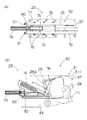
ここに、図1は本発明の一実施の形態に係る形鋼材の反転装置を適用した反転無しの場合の水平搬送状態の模式説明図、図2(A)、(B)、(C)はそれぞれ同形鋼材の反転装置を適用した反転有りの場合の搬送工程の模式説明図、図3(A)、(B)はそれぞれ同形鋼材の反転装置を適用して段積みした溝形鋼及び山形鋼の断面図である。
図1及び図2に示すように、本発明の一実施の形態に係る形鋼材の反転装置10は、後面装置11の上流側に配置された搬送装置の一例である傾斜式コンベア12と、傾斜式コンベア12の上流側に配置され、傾斜式コンベア12に形鋼材の一例である長尺の溝形鋼13を供給する供給装置の一例である入側コンベア14と、所定の傾斜角度に傾斜した傾斜式コンベア12に入側コンベア14から自然落下で供給される、反転中途の溝形鋼13を反転する形鋼材反転機構15とを有している。以下、これらの構造及び溝形鋼13の搬送、反転方法について詳しく説明する。
【0007】
入側コンベア14は、複数のヘッド側の駆動スプロケット16とテール側の従動スプロケット(図示せず)に複数列の無端ローラーチェーン17を掛け渡して構成されており、複数のヘッド側の駆動スプロケット16及びテール側の従動スプロケットはそれぞれ機械的に同期駆動され、長尺(例えば、6〜24m)の溝形鋼13を進行方向に傾斜させることなく平行に搬送できるようにしている。
傾斜式コンベア12は、1本の溝形鋼13を搬送可能な短尺のコンベアであって、入側コンベア14と同様、複数のヘッド側の駆動スプロケット18とテール側の従動スプロケット19に複数列の無端ローラーチェーン20を掛け渡して構成されている。傾斜式コンベア12の水平時には、図1に示すように、圧延終了後の開口部21を下側に向けた状態で入側コンベア14によって搬送される溝形鋼13が水平搬送状態を維持したまま、傾斜式コンベア12に乗り移って水平に搬送され、下流側の後面装置11に水平に乗り移ることができるように、無端ローラーチェーン17の第1の搬送面17aと無端ローラーチェーン20の第2の搬送面20aとが正面視して同一水平レベルを形成していると共に、無端ローラーチェーン20の第2の搬送面20aと後面装置11の搬送面11aとが正面視して同一水平レベルを形成している。従って、図1に示すように、傾斜式コンベア12が水平時には入側コンベア14から搬送される溝形鋼13はそのままの状態で、傾斜式コンベア12を介して後面装置11に搬送される。
【0008】
傾斜式コンベア12には、駆動スプロケット18の中心Aを傾動の回転軸として傾動可能なコンベア傾動機構22が設けられており、コンベア傾動機構22によって図2(A)に示すように、傾斜式コンベア12の第2の搬送面20aを傾斜させることができる。図のように第2の搬送面20aを傾斜させ、無端ローラーチェーン20の駆動を停止した状態で、入側コンベア14によって搬送される溝形鋼13を駆動スプロケット16部から落下させる。その結果、溝形鋼13の一側部13aが別途設けられる落下高さ位置調整機構23の形鋼材落下ガイド32(図7を参照)に当接すると共に、溝形鋼13の他側部13bも形鋼材落下ガイド32に当接した状態になって、溝形鋼13は反転前の適正な姿勢に保持されることになる。この状態で、形鋼材反転機構15を駆動して反転レバー24を図2(A)から図2(B)の矢印のように移動させて、溝形鋼13の底部13cが形鋼材落下ガイド32上に載置されるようにしている。
【0009】
なお、落下高さ位置調整機構23は、サイズ及び形状の異なる各種の形鋼材の自重落下後の姿勢を適正に保つため、即ち形鋼材がひっくりかえり過ぎないようにするために使用するものであり、その後、この状態の形鋼材に対して、反転レバー24によって確実に反転が可能になるように、入側コンベア14から自然落下する形鋼材の下端の位置決めを行うための機構である。従って、落下高さ位置調整機構23は、搬送材の条件や搬送条件等に応じて、高さを調整可能な構造としている。
【0010】
図2(B)のように底部13cが載置面23aに載置された溝形鋼13は、傾斜式コンベア12が駆動スプロケット18の中心Aを回転軸としてコンベア傾動機構22の駆動により傾動されることにより、第2の搬送面20aにて載置されて上昇した後、図2(C)のように元の水平状態になり、その後傾斜式コンベア12の無端ローラーチェーン20を駆動して、溝形鋼13を後面装置11に乗り継ぎ、搬送される。溝形鋼13は後面装置11に設けられたストッパー25によって停止し、溝形鋼13の下方からリフト手段26により後面装置11から所定の場所に搬送され、溝形鋼13の裏面(図2(B)及び(C)に示す状態)検査又は、段積み等が実施されることになる。
【0011】
従って、図1に示すように、圧延終了後の底部13cが上部となるようにして後面装置11に搬送された溝形鋼13と、一方、図2に示すように、傾斜式コンベア12、落下高さ位置調整機構23及び形鋼材反転機構15によって底部13cが下部となるようにして後面装置11に搬送された溝形鋼13とを所定の搬送間隔で交互にリフト手段26により所定の場所に搬送して、図3(A)に示すように、溝形鋼13の開口部21同士を対向させて配置して一段目の段積みを行うことができ、さらに一段目の段積みの上面27を形成する、同レベルに配置された溝形鋼13の連続する底部13c上に2段目の、対向する溝形鋼13を段積みすることができる。
なお、取り扱われる形鋼材として溝形鋼13について説明したが、山形鋼28の場合にも、図8及び図9に示すように、同様にして搬送又は反転され、図3(B)に示すように段積みできる。
【0012】
【実施例】
本発明の一実施の形態に係る形鋼材の反転装置10aの実施例について、図4〜図7を参照しながら説明する。
ここに、図4は本発明の一実施の形態に係る形鋼材の反転装置の概略構成図、図5(A)、(B)はそれぞれ傾斜式コンベアの正面図及び側面図、図6(A)、(B)はそれぞれ形鋼材反転機構の正面図及び側面図、図7(A)、(B)はそれぞれ落下高さ位置調整機構の平面図及び正面図である。
図4に示すように、形鋼材の反転装置10aは後面装置の一例であるスキューローラコンベア29の上流側に配置された、搬送装置の一例である傾斜式ローラーチェーンコンベア30と、傾斜式ローラーチェーンコンベア30の上流側に配置され、傾斜式ローラーチェーンコンベア30に、上述した形鋼材の一例である長尺の溝形鋼13(又は山形鋼28)を供給する供給装置の一例であるローラーチェーンコンベア31と、所定の傾斜角度に傾斜した傾斜式ローラーチェーンコンベア30にローラーチェーンコンベア31から形鋼材落下ガイド32(図7参照)を介して自然落下で供給される、反転中途の溝形鋼13を反転する形鋼材反転機構15と、形鋼材反転機構15の近傍に設けた図示しない落下高さ位置調整機構23とを有している。以下、これらについて詳しく説明する。
【0013】
図4に示すように、ローラーチェーンコンベア31は、複数列のヘッド側の駆動スプロケット33とテール側の従動スプロケット(図示せず)に複数列の無端ローラーチェーン34を掛け渡して構成されており、複数のヘッド側の駆動スプロケット33及びテール側の従動スプロケットはそれぞれ回転軸35を介して機械的に同期駆動され、長尺の溝形鋼13を進行方向に傾斜させることなく平行に搬送できるようにしている。
図4及び図5に示すように、傾斜式ローラーチェーンコンベア30は、1本の溝形鋼13を搬送可能な短尺のコンベアであって、ローラーチェーンコンベア31と同様、複数列のヘッド側の駆動スプロケット36とテール側の従動スプロケット37に複数列の無端ローラーチェーン38を掛け渡して構成されている。傾斜式ローラーチェーンコンベア30の従動スプロケット37の従動軸39と、ローラーチェーンコンベア31のヘッド側の駆動スプロケット33の回転軸35との位置関係は、傾斜式ローラーチェーンコンベア30の水平時の第2の搬送面30aとローラーチェーンコンベア31の第1の搬送面31aとが正面視して同一水平レベルを形成すると共に、第2の搬送面30aと第1の搬送面31aとが僅かに重なるように配置している。
【0014】
傾斜式ローラーチェーンコンベア30には、駆動スプロケット36の回転軸40を中心として傾動可能なコンベア傾動機構41が設けられている。駆動スプロケット36と駆動用スプロケット42を回転支持したコンベアフレーム43を、取付けフレーム44に取付けられた軸受45によって回転支持している。コンベアフレーム43の中間位置には、取付けブラケット46が固定されており、取付けブラケット46には作動ロッド47を介して、くの字状のレバー48の一端部が連結されている。レバー48の中央部には同期軸49が固着されており、同期軸49は複数の軸受49aによって軸支され、レバー48の他端部には、取付けフレーム44に取付けられた図示しないブラケットに軸支されたエアシリンダ50のロッド51が取付け金具52を介して連結されている。なお、他の列のコンベアフレーム43には、同期軸49に固着されたレバー(レバー48の上部のみ)を介して作動ロッド47が連結されている。
従って、エアシリンダ50を駆動することによって、取付け金具52、レバー48、同期軸49、作動ロッド47及び取付けブラケット46を介して複数列のコンベアフレーム43をそれぞれの回転軸40回りに回転することができる。
【0015】
傾斜式ローラーチェーンコンベア30の無端ローラーチェーン38の駆動は、コンベアフレーム43のヘッド側の駆動スプロケット36と一体的に取付けられた駆動用スプロケット42と、取付けフレーム44に取付けられた図外のものも含む軸受53によって回転支持された同期軸54に固着された駆動用スプロケット55との間に取付けられた無端チェーン56により行う。無端チェーン56の駆動は、駆動用スプロケット55と一体的に取付けられた同期用スプロケット57と、モータ58の出力軸にカップリング59を介して連結された減速機60の出力軸に取付けられた駆動用スプロケット61との間に取付けられた無端チェーン62により行うようになっている。なお、他の列の無端ローラーチェーン38の駆動は、同期軸54に固着された、図外の駆動用スプロケット(駆動用スプロケット55と同じ)により、前記と同様に無端チェーン56及び駆動用スプロケット42を介して駆動スプロケット36を駆動して行っている。図4及び図5中の符号63は、無端チェーン56の緊張用のスプロケットを表している。
従って、モータ58を駆動することによって、カップリング59、減速機60、駆動用スプロケット61、同期用スプロケット57を介して同期軸54を回転することによって複数列の駆動用スプロケット55を駆動し、各列の無端チェーン56により各列の無端ローラーチェーン38を回転することができる。
【0016】
形鋼材反転機構15は、図4及び図6に示すように、取付けフレーム44に取付けられた軸受64に回転支持された回動軸65に固着された反転レバー24を、回動軸65回りに図6(A)に示すように、回動することによって、形鋼材を反転するものである。
反転レバー24の先端は、待機位置Bでは、ローラーチェーンコンベア31の第1の搬送面31aの下方で、回転軸35より右側に位置しているが、回動限位置Cでは、傾斜式ローラーチェーンコンベア30の第2の搬送面30aの上方で、駆動スプロケット33の左端より左側に位置するようにしている。反転レバー24の中間部の下部には、ターンバックルを使用した長さ調整可能な作動ロッド66の一端部が軸支され、作動ロッド66の他端部は、取付けフレーム44に取付けられた軸受67に回転支持された同期軸68に固着されたレバー69の先端部に軸支されている。さらに同期軸68には駆動レバー70が固着されており、駆動レバー70の先端部は、取付けフレーム44に軸受71を介して取付けられたロッドトラニオン式のエアシリンダ72のロッド73の先端部に軸支されている。また、他の列の駆動レバー70は、作動ロッド66を介して同期軸68に固着されたレバー69に連結されている。
従って、エアシリンダ72の作動によって、駆動レバー70、同期軸68及び複数列のレバー69を介して作動ロッド66を駆動して、複数列の反転レバー24を回動軸65回りに回動することができる。
【0017】
落下高さ位置調整機構23は、図7(A)、(B)に示すように、取付けフレーム44に取付けられた形鋼材落下ガイド32と、形鋼材の落下時及び反転時の打ち傷を防止するために、上面にクッション材の一例であるウレタン等の樹脂材74が取付けられた、進退自在な落下高さ調整台車75とを有している。
形鋼材落下ガイド32は、図に2点鎖線で示すように、両サイドに配置された中央部が窪んだ形状を有する板材からなる2つの落下ガイド本体76が底板77によって連結された構造で、底板77は取付けフレーム44上に複数のボルト、ナット78によって固定されている。また、形鋼材落下ガイド32の後部には、落下高さ調整台車75を進退させるエアシリンダ79を取付けるためのシリンダ取付け板80が、ボルト81によって取り外し可能に取付けられている。
落下高さ調整台車75においては、台車本体82の上部には斜線で示す樹脂材74が設けられ、台車本体82の後部は、エアシリンダ79のロッドと取付け金具83を介して連結されている。また、台車本体82の下部には、底板77上に走行ガイドが設けられている。
従って、エアシリンダ79の駆動によって落下高さ調整台車75を前進させて、図7(B)の2点鎖線で示す位置まで樹脂材74の高さを高くすることができる。
【0018】
この結果、図7(B)に示すように、大きな山形鋼28の場合には、山形鋼28の下端が形鋼材落下ガイド32の落下ガイド本体76の中央部の窪みの底部に接触し、山形鋼28の上端が形鋼材落下ガイド32の落下ガイド本体76の上面に接触した状態にて反転レバー24によって反転を行い、一方、小さい山形鋼28aの場合には、落下高さ調整台車75を前進させて、図のように山形鋼28aの下端が樹脂材74の下部に接触し、山形鋼28aの上端が形鋼材落下ガイド32の落下ガイド本体76の上面に接触した状態にて反転レバー24によって反転を行なうことができる。
従って、形鋼材のサイズや形状に関係なく、形鋼材の自由落下後の姿勢を反転前に適正に保持することができる。
【0019】
前記実施の形態においては、供給装置として入側コンベア14で説明したが、これに限定されず、例えば、固定スキッド上、又は直交する方向から搬送されたローラーテーブル上の形鋼材をプッシャー等の押し込み装置を使用して、傾斜式コンベア12へ自然落下させても構わない。
また、傾斜式コンベア12は、駆動スプロケット18側を回転中心とし、従動スプロケット19側を傾動したが、これに限定されず、コンベア全体を昇降することも可能である。また、ローラーチェーン方式として説明したが、回動可能なスキッドを設けると共に、スキッド上に反転された形鋼材を後面装置に搬送する、プッシャー等の押し込み装置を設けることもできる。
落下高さ位置調整機構23は、落下高さ調整台車75を水平方向に進退自在にしたが、傾斜式ローラーチェーンコンベア30の第2の搬送面30aに垂直方向に移動することもできる。また、落下する形鋼材の姿勢をガイドする落下ガイド本体76の上面の形状は、取り扱う種々の形鋼材に対して最適な形状のものを選定する。
【0020】
前記実施の形態においては、形鋼材反転機構15及び落下高さ位置調整機構23は、傾斜式コンベア12とは切り離して別個に取付けフレーム44に取付けたが、必要に応じて傾斜式コンベアに取付けることもできる。
溝形鋼13の供給、搬送姿勢については、開口部21を下側にした状態で説明したが、この逆で開口部21を上側にした状態であってもよい。
形鋼材として、溝形鋼13及び山形鋼28について説明したが、落下高さ位置調整機構23を使用条件に合わせて決定すれば、鋼矢板等の他の形鋼材に対しても適用可能である。
入側コンベア14及び後面装置11の搬送面を水平としたが、形鋼材と搬送面との間の摩擦抵抗の範囲内で搬送面を多少傾斜させても構わない。
【0021】
【発明の効果】
請求項1記載の形鋼材の反転装置においては、供給装置の複数列の第1の搬送面と同一レベルにできると共に第1の搬送面の下方に連接側の複数列の第2の搬送面を移動可能な搬送装置を設け、連接部近傍には、供給装置から下方に落下する形鋼材の姿勢をガイドする落下ガイド本体と、落下高さ調整台車とを有し、供給装置から下方に落下する形鋼材の落下後の姿勢を適正に保持可能な落下高さ位置調整機構を、並設された第2の搬送面間に備え、かつ落下後の姿勢が適正に保持された形鋼材を反転可能な反転レバーを備えているので、極めて簡単な構造の装置によって、種々の大きさ又は形状の形鋼材を正転又は反転状態で後面装置に搬送できると共に、設置スペースやメンテナンス作業が有利となる。
そして、この形鋼材の反転装置においては、落下高さ位置調整機構及び/又は反転レバーを搬送装置と切り離して別途に設けているので、搬送装置をコンパクトな構造とすることができる。
【図面の簡単な説明】
【図1】本発明の一実施の形態に係る形鋼材の反転装置を適用した反転無しの場合の水平搬送状態の模式説明図である。
【図2】(A)、(B)、(C)はそれぞれ同形鋼材の反転装置を適用した反転有りの場合の搬送工程の模式説明図である。
【図3】(A)、(B)はそれぞれ同形鋼材の反転装置を適用して段積みした溝形鋼及び山形鋼の断面図である。
【図4】本発明の一実施の形態に係る形鋼材の反転装置の概略構成図である。
【図5】(A)、(B)はそれぞれ傾斜式コンベアの正面図及び側面図である。
【図6】(A)、(B)はそれぞれ形鋼材反転機構の正面図及び側面図である。
【図7】(A)、(B)はそれぞれ落下高さ位置調整機構の平面図及び正面図である。
【図8】本発明の一実施の形態に係る形鋼材の反転装置を適用した反転無しの場合の水平搬送状態の他の模式説明図である。
【図9】(A)、(B)、(C)はそれぞれ同形鋼材の反転装置を適用した反転有りの場合の搬送工程の他の模式説明図である。
【符号の説明】
10 形鋼材の反転装置 10a 形鋼材の反転装置
11 後面装置 11a 搬送面
12 傾斜式コンベア(搬送装置) 13 溝形鋼
13a 一側部 13b 他側部
13c 底部 14 入側コンベア(供給装置)
15 形鋼材反転機構 16 駆動スプロケット
17 無端ローラーチェーン 17a 第1の搬送面
18 駆動スプロケット 19 従動スプロケット
20 無端ローラーチェーン 20a 第2の搬送面
21 開口部 22 コンベア傾動機構
23 落下高さ位置調整機構 23a 載置面
24 反転レバー 25 ストッパー
26 リフト手段 27 上面
28 山形鋼 28a 山形鋼
29 スキューローラコンベア(後面装置)
30 傾斜式ローラーチェーンコンベア(搬送装置)
30a 第2の搬送面
31 ローラーチェーンコンベア(供給装置)
31a 第1の搬送面 32 形鋼材落下ガイド
33 駆動スプロケット 34 無端ローラーチェーン
35 回転軸 36 駆動スプロケット
37 従動スプロケット 38 無端ローラーチェーン
39 従動軸 40 回転軸
41 コンベア傾動機構 42 駆動用スプロケット
43 コンベアフレーム 44 取付けフレーム
45 軸受 46 取付けブラケット
47 作動ロッド 48 レバー
49 同期軸 49a 軸受
50 エアシリンダ 51 ロッド
52 取付け金具 53 軸受
54 同期軸 55 駆動用スプロケット
56 無端チェーン 57 同期用スプロケット
58 モータ 59 カップリング
60 減速機 61 駆動用スプロケット
62 無端チェーン 63 スプロケット
64 軸受 65 回動軸
66 作動ロッド 67 軸受
68 同期軸 69 レバー
70 駆動レバー 71 軸受
72 エアシリンダ 73 ロッド
74 樹脂材(クッション材) 75 落下高さ調整台車
76 落下ガイド本体 77 底板
78 ボルト、ナット 79 エアシリンダ
80 シリンダ取付け板 81 ボルト
82 台車本体 83 取付け金具[0001]
BACKGROUND OF THE INVENTION
TECHNICAL FIELD The present invention relates to a reversing device for a shaped steel material intended to be reversed in order to cool, inspect and stack a shaped steel material such as a steel sheet pile, channel steel, and angle steel after rolling.
[0002]
[Prior art]
2. Description of the Related Art Conventionally, as a reversing device for a shaped steel material for reversing a long shaped steel material for cooling, inspection, and stacking of the shaped steel material after rolling, a device described in JP-A-1-127518 is known. In the reversing device of the shape steel material of the form described in this gazette, on the rotating body rotatably attached to the carriage that runs on the frame, the mounted shape steel (implemented when rotated 90 °) In the example, the steel sheet pile has a receiving arm that is inclined in advance by an angle necessary to invert and fall due to its own weight, and a support arm that supports a side edge serving as a pivotal fulcrum of the section steel. In addition, a receiving arm is attached to the traveling carriage so that it can freely rotate. After the steel frame that is inverted and overturned is received by the receiving arm in the middle of the inversion, the steel frame is inverted and overturned by the rotation return operation. The rotating body and the receiving arm are rotated with respect to the carriage by using the traveling movement operation of the carriage with respect to the frame. Therefore, the shape steel can be reversed with a small rotation operation in conjunction with the traveling of the carriage.
[0003]
[Problems to be solved by the invention]
However, the shape steel reversing device described in JP-A-1-127518 still has the following problems to be solved.
There is no problem when reversing steel sheet piles of the same size, but when reversing steel sheet piles of significantly different sizes, or when reversing other shapes such as channel steel and angle steel, Due to the difference in size and the difference in cross-sectional shape, it was difficult to reliably reverse the shape steel material.
In addition, since the structure of the apparatus is complicated, there is a problem that a large installation space is required and maintenance work is troublesome.
[0004]
The present invention has been made in view of such circumstances, and it is possible to reverse a shape steel material of any shape and size, and because the structure of the apparatus is simple, the reversal of the shape steel material is advantageous for installation space and maintenance work. An object is to provide an apparatus.
[0005]
[Means for Solving the Problems]
The structural steel reversing device according to
A transport device that can be at the same level as the first transport surfaces of the plurality of rows of the supply device and can move the second transport surfaces of the plurality of rows on the connection side is provided below the first transport surface,
The connecting portion near the drop guide body for guiding the posture of the shaped steel material falling down from the supply device, the drop height position adjusting mechanism having a drop height adjustment carriage, juxtaposed the second The fall height position adjustment mechanism is provided between the conveyance surfaces , and the fall height adjustment carriage can be adjusted in height by moving the fall height adjustment carriage in the horizontal direction or in the direction perpendicular to the second conveyance surface. A reversing lever capable of reversing the shape steel material in which the shape steel material falling downward from the supply device is not overturned and in which the posture after the fall is properly maintained is provided; Alternatively, the reversing lever is separately provided from the conveying device.
[0006]
DETAILED DESCRIPTION OF THE INVENTION
Next, embodiments of the present invention will be described with reference to the accompanying drawings for understanding of the present invention.
Here, FIG. 1 is a schematic explanatory view of a state of horizontal conveyance in the case of no reversal to which the reversing device for a shaped steel material according to one embodiment of the present invention is applied, and FIGS. 2 (A), (B), (C) are 3A and 3B are schematic explanatory views of the conveying process in the case of reversal using the reversing device of the same shape steel material, respectively, and FIGS. 3A and 3B are the grooved steel and the angle steel stacked by applying the reversing device of the same shape steel material respectively. FIG.
As shown in FIG.1 and FIG.2, the
[0007]
The inlet-
The
[0008]
The tilting
[0009]
The drop height
[0010]
As shown in FIG. 2B, the
[0011]
Therefore, as shown in FIG. 1, the grooved
In addition, although the grooved
[0012]
【Example】
An example of a reversing device 10a for a shaped steel material according to an embodiment of the present invention will be described with reference to FIGS.
Here, FIG. 4 is a schematic configuration diagram of a reversing device for a shaped steel material according to an embodiment of the present invention, FIGS. 5A and 5B are a front view and a side view of an inclined conveyor, respectively, and FIG. FIGS. 7A and 7B are a plan view and a front view, respectively, of the drop height position adjusting mechanism.
As shown in FIG. 4, the shape steel reversing device 10 a is disposed on the upstream side of a
[0013]
As shown in FIG. 4, the
As shown in FIGS. 4 and 5, the inclined
[0014]
The inclined
Therefore, by driving the
[0015]
The
Therefore, by driving the
[0016]
As shown in FIGS. 4 and 6, the structural steel
At the standby position B, the tip of the reversing
Therefore, by actuating the
[0017]
As shown in FIGS. 7A and 7B, the drop height
The shape steel
In the drop
Therefore, the height of the
[0018]
As a result, as shown in FIG. 7B, in the case of a
Therefore, regardless of the size and shape of the shape steel material, the posture after the free fall of the shape steel material can be properly maintained before reversal.
[0019]
In the said embodiment, although the
Further, the
The drop height
[0020]
In the above-described embodiment, the shape steel
The supply and conveyance posture of the
As the shape steel material, the
Although the conveyance surface of the
[0021]
【The invention's effect】
In the reversing device for the structural steel material according to
In this reversing device for the shaped steel material, the drop height position adjusting mechanism and / or the reversing lever are separately provided separately from the transport device, so that the transport device can have a compact structure.
[Brief description of the drawings]
FIG. 1 is a schematic explanatory diagram of a state of horizontal conveyance in the case of no reversal to which a reversing apparatus for a shaped steel material according to an embodiment of the present invention is applied.
FIGS. 2A, 2B, and 2C are schematic explanatory views of a conveying process in the case of reversal with application of a reversing device for isomorphous steel materials, respectively.
FIGS. 3A and 3B are cross-sectional views of channel steel and angle steel stacked by applying a reversing device of the same shape steel material, respectively.
FIG. 4 is a schematic configuration diagram of a reversing device for a shaped steel material according to an embodiment of the present invention.
FIGS. 5A and 5B are a front view and a side view of an inclined conveyor, respectively.
6A and 6B are a front view and a side view, respectively, of a shape steel material reversing mechanism.
7A and 7B are a plan view and a front view of a drop height position adjusting mechanism, respectively.
FIG. 8 is another schematic explanatory view of the state of horizontal conveyance when there is no reversal to which the reversing device for a shaped steel material according to one embodiment of the present invention is applied.
FIGS. 9A, 9B, and 9C are other schematic explanatory views of a conveying process in a case where reversal is applied to which a reversing device of the same shape steel material is applied, respectively.
[Explanation of symbols]
DESCRIPTION OF
15 Shaped
30 Inclined roller chain conveyor (conveyor)
30a
31a
Claims (1)
前記供給装置の複数列の第1の搬送面と同一レベルにできると共に該第1の搬送面の下方に、連接側の複数列の第2の搬送面を移動可能な搬送装置を設け、
連接部近傍には、前記供給装置から下方に落下する形鋼材の姿勢をガイドする落下ガイド本体と、落下高さ調整台車とを有する落下高さ位置調整機構を、並設された前記第2の搬送面間に備え、該落下高さ位置調整機構は、前記落下高さ調整台車を水平方向又は前記第2の搬送面に垂直な方向に移動して前記形鋼材の下端を高さ調整可能として前記供給装置から下方に落下する形鋼材がひっくりかえり過ぎないようにし、かつ前記落下後の姿勢が適正に保持された前記形鋼材を反転可能な反転レバーを備え、前記落下高さ位置調整機構及び/又は前記反転レバーを前記搬送装置と切り離して別途に備えたことを特徴とする形鋼材の反転装置。A reversing device for a structural steel material connected to the feeding device, which conveys the structural steel material conveyed from the upstream feeding device as it is or is reversed and conveyed to the downstream side,
A transport device that can be at the same level as the first transport surfaces of the plurality of rows of the supply device and can move the second transport surfaces of the plurality of rows on the connection side is provided below the first transport surface,
The connecting portion near the drop guide body for guiding the posture of the shaped steel material falling down from the supply device, the drop height position adjusting mechanism having a drop height adjustment carriage, juxtaposed the second The fall height position adjustment mechanism is provided between the conveyance surfaces , and the fall height adjustment carriage can be adjusted in height by moving the fall height adjustment carriage in the horizontal direction or in the direction perpendicular to the second conveyance surface. A reversing lever capable of reversing the shape steel material in which the shape steel material falling downward from the supply device is not overturned and in which the posture after the fall is properly maintained is provided; Alternatively, a reversing device for a shaped steel material, wherein the reversing lever is separately provided from the conveying device.
Priority Applications (1)
| Application Number | Priority Date | Filing Date | Title |
|---|---|---|---|
| JP11152498A JP4166323B2 (en) | 1998-04-06 | 1998-04-06 | Shape steel reversing device |
Applications Claiming Priority (1)
| Application Number | Priority Date | Filing Date | Title |
|---|---|---|---|
| JP11152498A JP4166323B2 (en) | 1998-04-06 | 1998-04-06 | Shape steel reversing device |
Publications (2)
| Publication Number | Publication Date |
|---|---|
| JPH11292258A JPH11292258A (en) | 1999-10-26 |
| JP4166323B2 true JP4166323B2 (en) | 2008-10-15 |
Family
ID=14563525
Family Applications (1)
| Application Number | Title | Priority Date | Filing Date |
|---|---|---|---|
| JP11152498A Expired - Fee Related JP4166323B2 (en) | 1998-04-06 | 1998-04-06 | Shape steel reversing device |
Country Status (1)
| Country | Link |
|---|---|
| JP (1) | JP4166323B2 (en) |
Families Citing this family (4)
| Publication number | Priority date | Publication date | Assignee | Title |
|---|---|---|---|---|
| JP2011256027A (en) * | 2010-06-10 | 2011-12-22 | Shibuya Machinery Co Ltd | Case reversing device |
| CN107352249A (en) * | 2016-12-23 | 2017-11-17 | 长沙世通纸塑箸业有限公司 | A kind of flat chopsticks turning device |
| CN116281051B (en) * | 2023-05-20 | 2023-08-22 | 唐山市丰润区宏运金属制品有限公司 | Angle steel turning device |
| CN117023088B (en) * | 2023-10-10 | 2023-12-22 | 烟台亿众智能科技有限公司 | Automatic overturning and stacking device for concave parts |
-
1998
- 1998-04-06 JP JP11152498A patent/JP4166323B2/en not_active Expired - Fee Related
Also Published As
| Publication number | Publication date |
|---|---|
| JPH11292258A (en) | 1999-10-26 |
Similar Documents
| Publication | Publication Date | Title |
|---|---|---|
| US7631744B2 (en) | Device for transporting printed products | |
| US5699892A (en) | Chain type transfer device | |
| JP4166323B2 (en) | Shape steel reversing device | |
| JP2010143743A (en) | Cardboard transfer device | |
| JP2002060050A (en) | Sheet inverting device | |
| JP2718877B2 (en) | Rotating transfer device for plate | |
| JP4462784B2 (en) | Paper feeder | |
| JP2008150142A (en) | Paper feeding device | |
| JP4054458B2 (en) | Sheet conveying device stacking device | |
| JPH06219548A (en) | Sheet conveyor system | |
| JP2008156075A (en) | Paper feed device | |
| JP4289200B2 (en) | Transport equipment | |
| JP2000118755A (en) | Paper feeding machine | |
| JP2517571B2 (en) | Rolling conveyance method for long material with L-shaped cross section | |
| JP3586572B2 (en) | Sheet feeder | |
| GB2167035A (en) | Installation for filling and closing open top bags | |
| KR102094125B1 (en) | A device for preventing the strip from falling off | |
| JP2638577B2 (en) | Split concrete block sorting method and apparatus | |
| JP2008189405A (en) | Sheet feeding method | |
| JP4618242B2 (en) | Sheet material rolling machine | |
| JPS6013933B2 (en) | Plate-shaped object feeding device | |
| JP2001345551A (en) | Board carriage mechanism in reflow-soldering apparatus | |
| JP2561366Y2 (en) | Transfer device | |
| JPH0776063B2 (en) | Paper feeder | |
| JPS5856694B2 (en) | Plate-shaped object feeding device |
Legal Events
| Date | Code | Title | Description |
|---|---|---|---|
| A621 | Written request for application examination |
Free format text: JAPANESE INTERMEDIATE CODE: A621 Effective date: 20041217 |
|
| A711 | Notification of change in applicant |
Free format text: JAPANESE INTERMEDIATE CODE: A712 Effective date: 20060808 |
|
| RD02 | Notification of acceptance of power of attorney |
Free format text: JAPANESE INTERMEDIATE CODE: A7422 Effective date: 20061010 |
|
| A977 | Report on retrieval |
Free format text: JAPANESE INTERMEDIATE CODE: A971007 Effective date: 20071203 |
|
| A131 | Notification of reasons for refusal |
Free format text: JAPANESE INTERMEDIATE CODE: A131 Effective date: 20080115 |
|
| A521 | Written amendment |
Free format text: JAPANESE INTERMEDIATE CODE: A523 Effective date: 20080306 |
|
| A131 | Notification of reasons for refusal |
Free format text: JAPANESE INTERMEDIATE CODE: A131 Effective date: 20080507 |
|
| A521 | Written amendment |
Free format text: JAPANESE INTERMEDIATE CODE: A523 Effective date: 20080610 |
|
| TRDD | Decision of grant or rejection written | ||
| A01 | Written decision to grant a patent or to grant a registration (utility model) |
Free format text: JAPANESE INTERMEDIATE CODE: A01 Effective date: 20080708 |
|
| A01 | Written decision to grant a patent or to grant a registration (utility model) |
Free format text: JAPANESE INTERMEDIATE CODE: A01 |
|
| A61 | First payment of annual fees (during grant procedure) |
Free format text: JAPANESE INTERMEDIATE CODE: A61 Effective date: 20080730 |
|
| FPAY | Renewal fee payment (event date is renewal date of database) |
Free format text: PAYMENT UNTIL: 20110808 Year of fee payment: 3 |
|
| FPAY | Renewal fee payment (event date is renewal date of database) |
Free format text: PAYMENT UNTIL: 20110808 Year of fee payment: 3 |
|
| FPAY | Renewal fee payment (event date is renewal date of database) |
Free format text: PAYMENT UNTIL: 20120808 Year of fee payment: 4 |
|
| FPAY | Renewal fee payment (event date is renewal date of database) |
Free format text: PAYMENT UNTIL: 20120808 Year of fee payment: 4 |
|
| FPAY | Renewal fee payment (event date is renewal date of database) |
Free format text: PAYMENT UNTIL: 20130808 Year of fee payment: 5 |
|
| S531 | Written request for registration of change of domicile |
Free format text: JAPANESE INTERMEDIATE CODE: R313531 |
|
| FPAY | Renewal fee payment (event date is renewal date of database) |
Free format text: PAYMENT UNTIL: 20130808 Year of fee payment: 5 |
|
| S531 | Written request for registration of change of domicile |
Free format text: JAPANESE INTERMEDIATE CODE: R313531 |
|
| R350 | Written notification of registration of transfer |
Free format text: JAPANESE INTERMEDIATE CODE: R350 |
|
| R350 | Written notification of registration of transfer |
Free format text: JAPANESE INTERMEDIATE CODE: R350 |
|
| FPAY | Renewal fee payment (event date is renewal date of database) |
Free format text: PAYMENT UNTIL: 20130808 Year of fee payment: 5 |
|
| S533 | Written request for registration of change of name |
Free format text: JAPANESE INTERMEDIATE CODE: R313533 |
|
| FPAY | Renewal fee payment (event date is renewal date of database) |
Free format text: PAYMENT UNTIL: 20130808 Year of fee payment: 5 |
|
| R350 | Written notification of registration of transfer |
Free format text: JAPANESE INTERMEDIATE CODE: R350 |
|
| R250 | Receipt of annual fees |
Free format text: JAPANESE INTERMEDIATE CODE: R250 |
|
| R250 | Receipt of annual fees |
Free format text: JAPANESE INTERMEDIATE CODE: R250 |
|
| R250 | Receipt of annual fees |
Free format text: JAPANESE INTERMEDIATE CODE: R250 |
|
| R250 | Receipt of annual fees |
Free format text: JAPANESE INTERMEDIATE CODE: R250 |
|
| LAPS | Cancellation because of no payment of annual fees |